EP2466716A2 - Kontaktlose Stromzuführungsvorrichtung - Google Patents
Kontaktlose Stromzuführungsvorrichtung Download PDFInfo
- Publication number
- EP2466716A2 EP2466716A2 EP11181661A EP11181661A EP2466716A2 EP 2466716 A2 EP2466716 A2 EP 2466716A2 EP 11181661 A EP11181661 A EP 11181661A EP 11181661 A EP11181661 A EP 11181661A EP 2466716 A2 EP2466716 A2 EP 2466716A2
- Authority
- EP
- European Patent Office
- Prior art keywords
- coil
- power
- power feeding
- power receiving
- power transmission
- Prior art date
- Legal status (The legal status is an assumption and is not a legal conclusion. Google has not performed a legal analysis and makes no representation as to the accuracy of the status listed.)
- Withdrawn
Links
Images


Classifications
-
- H—ELECTRICITY
- H02—GENERATION; CONVERSION OR DISTRIBUTION OF ELECTRIC POWER
- H02J—CIRCUIT ARRANGEMENTS OR SYSTEMS FOR SUPPLYING OR DISTRIBUTING ELECTRIC POWER; SYSTEMS FOR STORING ELECTRIC ENERGY
- H02J50/00—Circuit arrangements or systems for wireless supply or distribution of electric power
- H02J50/40—Circuit arrangements or systems for wireless supply or distribution of electric power using two or more transmitting or receiving devices
- H02J50/402—Circuit arrangements or systems for wireless supply or distribution of electric power using two or more transmitting or receiving devices the two or more transmitting or the two or more receiving devices being integrated in the same unit, e.g. power mats with several coils or antennas with several sub-antennas
-
- H—ELECTRICITY
- H02—GENERATION; CONVERSION OR DISTRIBUTION OF ELECTRIC POWER
- H02J—CIRCUIT ARRANGEMENTS OR SYSTEMS FOR SUPPLYING OR DISTRIBUTING ELECTRIC POWER; SYSTEMS FOR STORING ELECTRIC ENERGY
- H02J50/00—Circuit arrangements or systems for wireless supply or distribution of electric power
- H02J50/10—Circuit arrangements or systems for wireless supply or distribution of electric power using inductive coupling
- H02J50/12—Circuit arrangements or systems for wireless supply or distribution of electric power using inductive coupling of the resonant type
-
- H—ELECTRICITY
- H02—GENERATION; CONVERSION OR DISTRIBUTION OF ELECTRIC POWER
- H02J—CIRCUIT ARRANGEMENTS OR SYSTEMS FOR SUPPLYING OR DISTRIBUTING ELECTRIC POWER; SYSTEMS FOR STORING ELECTRIC ENERGY
- H02J50/00—Circuit arrangements or systems for wireless supply or distribution of electric power
- H02J50/70—Circuit arrangements or systems for wireless supply or distribution of electric power involving the reduction of electric, magnetic or electromagnetic leakage fields
Definitions
- the present invention relates to a non-contact power feeding apparatus, and more particularly to a non-contact power feeding apparatus adapted to feed power with no contact from, for example, a power feeding side of a ground surface side to a power receiving side of a vehicle side.
- a non-contact power feeding apparatus adapted to feed power from outside to, for example, a vehicle such as an electric vehicle without any mechanical contact such as a cable has been developed based on the demand and this apparatus is in practical use.
- a non-contact power feeding apparatus power is fed through an air gap of, for example, tens of millimeters to hundreds of millimeters from a power transmission coil of a power feeding side circuit fixedly disposed on the ground side to a power receiving coil of a power receiving side circuit mounted on the side of a movable body such as a vehicle, based on a mutual induction effect of electromagnetic induction (refer to Figs. 4 and 5 described below).
- Fig. 3 shows a conventional non-contact power feeding apparatus 1 of this type, wherein Fig. 3A is a plan view of the power receiving coil 3 (the power transmission coil 2), Fig. 3B is a front view showing a condition of the electromagnetic field radiation etc., and Fig. 3C is a plan view showing the same condition as in Fig. 3B .
- the power transmission coil 2 of the power feeding side circuit 4 and the power receiving coil 3 of the power receiving side circuit 5 have always been formed in a spirally wound flat structure, respectively.
- the power transmission coil 2 and the power receiving coil 3 are respectively composed of one unit coil (that is, a 2-pole coil with 2 pole numbers composed of the north and south poles) to provide a 2-pole structure.
- Reference numeral 6 in Fig. 3 is a magnetic core such as a ferrite core which is respectively disposed outside the power transmission coil 2 and the power receiving coil 3.
- Reference letter G is an air gap
- H is an alternating magnetic field formed
- h is one example of the direction of the magnetic field H
- N is its north pole
- S is its south pole
- I shows the direction of an electric current.
- D shows the electromagnetic field radiation and r shows the electromagnetic field strength.
- Such a conventional non-contact power feeding apparatus 1 of this type is disclosed, for example, in the following Patent Documents 1 and 2.
- the power transmission coil 2 and the power receiving coil 3 are electromagnetically coupled by utilizing the induced magnetic field H to form a magnetic path of a magnetic flux, wherein non-contact power feeding is conducted (As shown in Fig. 3B as a typical example, the power receiving coil 3 and the power transmission coil 2 are vertically located and the problems will now be described based on the positional relationship).
- the electromagnetic field radiation D is free to diffuse.
- the electromagnetic field radiation D and the electromagnetic field strength r which are externally diffused to propagate in a substantially planar manner show the non-directional characteristics, that is, the isotropic characteristics as shown in Fig. 3C .
- such electromagnetic field radiation D and the electromagnetic field strength r in the lateral and vertical directions may cause electromagnetic disturbance in the neighborhood.
- the strong high-frequency magnetic field H (the alternating magnetic field H) is induced to strongly radiate high-frequency electromagnetic waves
- the electromagnetic waves readily reach a neighboring area and may cause an adverse effect on the environment.
- the high-frequency electromagnetic waves may generate electronic jamming or produce a functional disorder to the human body in the area of, for example, tens of meters to hundreds of meters away.
- expansion of the air gap G is proportional to an increase in the exciting reactive power of the power transmission coil 2 and it is necessary to increase the exciting apparent power.
- the expansion of the air gap G results in the expansion of the electromagnetic field radiation D to the outside and the increase of the electromagnetic field strength r, thereby leading to the increase in risk of electromagnetic disturbance to the neighborhood as described above.
- a non-contact power feeding apparatus of the present invention was developed to solve the problems of the conventional technology.
- a technical means of the present invention is as follows as per claims 1 ⁇ 7.
- a non-contact power feeding apparatus in which power is fed through an air gap, with no contact, from a power transmission coil of a power feeding side circuit to a power receiving coil of a power receiving side circuit, which are closely disposed to face each other, based on a mutual induction effect of electromagnetic induction.
- the power transmission coil and the power receiving coil are respectively composed of a planar assembly of a number of unit coils.
- Each unit coil is formed in a spirally wound flat structure to be juxtaposed to another, wherein the direction of an electric current is set in reverse between each unit coil which is juxtaposed to the other to directly come into line.
- the non-contact power feeding apparatus according to the present invention can be modified by adding technically limited elements.
- power can be fed by a stop-type power feeding method whereby, in the case of power feeding, the power receiving coil is positioned in close proximity facing the stationary power transmission coil.
- the power transmission coil and the power receiving coil are formed in a vertically paired symmetric structure.
- one unit coil is composed of paired north and south poles to be taken as a double-pole with 2 pole numbers.
- the power transmission coil and the power receiving coil are therefore respectively taken as a 4-pole structure, an 8-pole structure or a multi-pole structure when an even number of unit coils is assembled.
- the direction of an electric current is set in reverse to make the north and south magnetic poles to be reversed between each unit coil which is juxtaposed to another to directly come into line.
- the unit coils which are juxtaposed to another to directly come into line, are provided in such a manner that an overlapping area of the respectively formed magnetic field cancels another area out to be offset based on the reverse north and south magnetic poles, thereby reducing the externally radiated electromagnetic waves in total.
- the power transmission coil and the power receiving coil are respectively provided outside with a magnetic core such as a ferrite core of a flat structure.
- the power feeding side circuit such as the power transmission coil is fixedly disposed on the ground side such as a ground surface, a road surface or a floor surface, while the power receiving side circuit such as the power receiving coil is mounted on the side of a vehicle or other movable body.
- the power transmission coil and the power receiving coil are provided with, for example, a 4-pole structure, an 8-pole structure or a multi-pole structure, and the direction of an electric current and the north and south poles are made in reverse between each unit coil which is juxtaposed to the other to directly come into line.
- the non-contact power feeding apparatus of the present invention can prevent a risk of generating electronic jamming or of producing a functional disorder to the human body in the area of, for example, tens of meters to hundreds of meters away.
- an air gap can be expanded.
- the electromagnetic waves radiated to the outside can be drastically reduced in total to prevent the possible electromagnetic disturbance.
- the non-contact power feeding apparatus of the present invention makes it possible to provide a larger air gap. Expansion of the air gap results in the increase of the exciting reactive power and the exciting apparent power, but the adverse effect can be covered (offset) by the first effect described above.
- the non-contact power feeding apparatus there is a great need for the expansion of air gap (i.e., realization of a large air gap) in view of the convenience of power feeding and it is possible to meet such a need.
- the present invention has prominent effects in that all the problems of the conventional example of this kind can be solved by the first and second effects.
- Non-contact power feeding apparatus 7 (Non-contact power feeding apparatus 7)
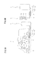
- a non-contact power feeding apparatus 7 which becomes the premise of the present invention will now be generally described with reference to Figs. 4 and 5 .
- the non-contact power feeding apparatus 7 is provided in such a manner that electric power is fed through an air gap G, with no contact, from a power transmission coil 8 of a power feeding side circuit 4 to a power receiving coil 9 of a power receiving side circuit 5, which are closely located to face each other, based on a mutual induction effect of the electromagnetic induction.
- the power feeding side circuit 4 is fixedly disposed on the side of the ground A, while the power receiving side circuit 5 is mounted on the side of a movable body such as a vehicle B.
- the power feeding side circuit 4 on the power feeding side, the track side or the primary side is fixedly disposed on the side of a ground surface, a road surface, a floor surface or other ground A at a power feeding area such as a power feeding stand C.
- the power receiving side circuit 5 on the power receiving side, the pickup side or the secondary side is mounted on a vehicle B such as an electric vehicle or an electric train, or other movable body.
- the power receiving side circuit 5 is available not only for driving, but also for non-driving.
- the power receiving side circuit 5 is usually connected to a car-mounted battery 10, but, as shown in Fig. 4 , it can also be connected direct to various types of loads 11.
- the power transmission coil 8 of the power feeding side circuit 4 and the power receiving coil 9 of the power receiving side circuit 5 are closely located to face each other with no contact through an air gap G which is a small space of, for example, 50mm to 150mm.
- a stop-type power feeding method is typical whereby the power receiving coil 9 is positioned to face the stationary power transmission coil 8 from above.
- the power transmission coil 8 and the power receiving coil 9 are formed in a vertically paired symmetric structure.
- it is also possible to adopt a mobile-type power feeding method whereby power feeding is conducted while the power receiving coil 9 runs at a low speed over the power transmission coil 8.
- the power transmission coil 8 of the power feeding side circuit 4 is connected to a power source 12.
- the power source 12 is composed of an inverter for converting a frequency and the like which applies a high frequency alternating current of, for example, several kHz to tens of kHz, moreover, tens of kHz to hundreds of kHz, to the power transmission coil 8 as a power feeding alternating current, that is, an exciting current.
- reference numeral 13 is a choke coil
- 14 is a capacitor for series resonance with the power transmission coil 8
- 15 is a capacitor for parallel resonance with the power transmission coil 8.
- the power receiving coil 9 of the power receiving side circuit 5 can be connected to the battery 10 in the example as shown in Fig. 5 , wherein a running motor 16 is driven by the battery 10 charged by the power feeding operation.
- a running motor 16 is driven by the battery 10 charged by the power feeding operation.
- power is fed to another load 11.
- Reference numeral 17 of Fig. 5 is a converter (a rectifying section and a smooth section) for converting an alternating current to a direct current and 18 is an inverter for converting the direct current to the alternating current.
- reference numeral 19 is a capacitor for parallel resonance with the power receiving coil 9.
- the power transmission coil 8 and the power receiving coil 9 are respectively formed in a spirally wound flat structure.
- the power transmission coil 8 and the power receiving coil 9 are provided in such a manner that each insulated coil conducting wire is spirally wound more than once in a circular or rectangular shape while maintaining the parallel positional relationship juxtaposed on the same plane.
- the power transmission coil 8 and the power receiving coil 9 are respectively formed in a thin, flat structure of a circular or substantially flange shape as a whole.
- the power transmission coil 8 and the power receiving coil 9 are respectively provided outside with a magnetic core 6 such as a ferrite core of a flat structure.
- the magnetic core 6 is made of a ferromagnetic body of a flat, circular or substantially flange shape and is concentrically disposed with and has a larger surface area than the power transmission coil 8 and the power receiving coil 9.
- the magnetic core 6 increases the inductance between coils to strengthen the electromagnetic coupling and induces, collects and directs the formed magnetic flux.
- the self-induced electromotive force is caused to generate by applying a power feeding alternating current, that is, an exciting current to the power transmission coil 8 of the power feeding side circuit 4 from the power source 12 to generate a magnetic field H around the power transmission coil 8, thereby forming a magnetic flux in the direction perpendicular to the coil surface.
- a power feeding alternating current that is, an exciting current to the power transmission coil 8 of the power feeding side circuit 4 from the power source 12 to generate a magnetic field H around the power transmission coil 8, thereby forming a magnetic flux in the direction perpendicular to the coil surface.
- the magnetic flux formed in this way goes through and interlinks the power receiving coil 9 of the power receiving side circuit 5 to generate the induced electromotive force, thereby forming the magnetic field H.
- the electric power is sent and received utilizing the induced magnetic field H.
- power of 1 kW to several kW, moreover, tens of kW to hundreds of kW can be fed.
- a magnetic path of a magnetic flux is formed to provide electromagnetic coupling between the power transmission coil 8 and the power receiving coil 9, wherein the non-conduct power feeding is transmitted.
- the general description of the non-contact power feeding apparatus 7 is as above.
- a non-contact power feeding apparatus 7 of embodiments of the present invention will now be described with reference to Figs. 1 and 2 .
- an outline of the present invention is as follows.
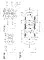
- the power transmission coil 8 is composed of a planar assembly of a number of unit coils 8'.
- the power receiving coil 9 is also composed of a planar assembly of a number of unit coils 9'.
- Each unit coil 8' of the power transmission coil 8 is juxtaposed to each other and the direction of an electric current I is reversed to make the north and south magnetic poles reverse between each unit coil 8' which is juxtaposed to another to directly come into line.
- each unit coil 9' of the power receiving coil 9 is also juxtaposed to another and the direction of the electric current I is set in reverse to make the north and south magnetic poles reverse between each unit coil 9' which is juxtaposed to another to directly come into line.
- the unit coils 8' (9') which are juxtaposed to each other to directly come into line are provided in such a manner that an overlapping area of each magnetic field H cancels another out to be offset based on the reverse north and south magnetic poles and as a result, the electromagnetic waves radiated to the outside are reduced in total.
- the power transmission coil 8 (the power receiving coil 9) is composed of a planar assembly of a number of unit coils 8' (9'), wherein a number of unit coils 8' (9') is juxtaposed one to another.
- Fig. 1A In the first example of Fig. 1A , two unit coils 8' (9') are used and in the second example of Fig. 1B , four unit coils 8' (9') are used. In this manner, an example with an even number of unit coils 8' (9') such as 2 unit coils, 4 unit coils or 8 unit coils is typical, but an example with an odd number of unit coils more than 3 is also available.
- a number of unit coils 8' (9') is juxtaposed one to another.
- the unit coils 8' (9') are closely juxtaposed one to another.
- a space is provided between each unit coil 8' (9') or there may be a mixed case.
- each unit coil 8' (9') is laterally disposed to form a line (in the X direction), but unlike this example, there is another case where each unit coil 8' (9') is vertically disposed to form a line (in the Y direction), or as in the second example, there is also a case where each unit coil 8' (9') is laterally and vertically disposed (in the X and Y directions).
- Each unit coil 8' (9') is juxtaposed to another.
- the direction of an electric current I is set in reverse between each unit coil 8' (9') which is juxtaposed to another to directly come into line.
- the direction of electric current I is made to reverse between two unit coil 8' (9') which are juxtaposed to each other to directly come into line in the lateral direction (in the X direction).
- the direction of electric current I is set to reverse between each unit coil 8' (9') which is juxtaposed to another to directly come into line in the lateral direction (in the X direction) and in the vertical direction (in the Y direction).
- the unit coils 8' (9') which are juxtaposed to another to directly come into line in the lateral and/or vertical direction are provided in such a manner that the direction of electric current I is set in reverse.
- each unit coil 8' (9') As a method of setting the direction of electric current I in reverse between the predetermined unit coils 8' (9'), it is a typical example that a series connection is made between each unit coil 8' (9') and the connection wiring between each unit coil 8' (9') is crossed on the way to make the coil wiring direction reverse between each unit coil 8' (9'). However, It is also possible to make each unit coil 8' (9') an opposite phase (without making the coil unit coordinate phase) and to make the coil winding direction the same.
- the direction of electric current I is as described above.
- the magnetic poles of the magnetic field H induced based on the induced electromotive force are caused to reverse with respect to each other to provide the north and south magnetic poles between two unit coils 8' (9') which are juxtaposed to directly come into line in the lateral (X) direction.
- the magnetic poles of the magnetic field H induced based on the induced electromotive force are provided in reverse to one other to provide the reverse north and south magnetic poles between each unit coil 8' (9') which is juxtaposed to another to directly come into line in the lateral (X) direction and in the vertical (Y) direction.
- each unit coil 8' forming the power transmission coil 8 and each unit coil 9' forming the power receiving coil 9 are closely located to face each other to be paired in the case of the power feeding operation.
- the paired north and south poles are formed between one unit coil 8' of the power transmission coil 8 and one unit coil 9' of the power receiving coil 9.
- one unit coil 8' of the power transmission coil 8 and one unit coil 9' of the power receiving coil 9 are respectively taken as a 2-pole coil with 2 pole numbers composed of the north and south poles.
- the power transmission coil 8 and the power receiving coil 9 of this non-contact power feeding apparatus 7 are taken as a multi-pole coil structure with 4 poles or more by the power transmission coil 8 composed of an assembly of a number of the unit coils 8' and the power receiving coil 9 composed of an assembly of a number of the unit coils 9'.
- the power transmission coil 8 (the power receiving coil 9) of the first example is taken as a 4-pole coil structure
- the power transmission coil 8 (the power receiving coil 9) of the second example is taken as an 8-pole coil structure
- the power transmission coil 2 and the power receiving coil 3 according to the conventional example of this type as shown in Fig. 3 are respectively taken as a 2-pole coil structure).
- the magnetic poles etc. are as described above.
- the magnetic poles that is, the north and south poles are reversed between each unit coil 8' (9') which is juxtaposed to the other to directly come into line as shown in Figs. 1A and 1B .
- a number of magnetic fields H is formed for each unit coil 8' and 9' to be paired between each unit coil 8' of the power transmission coil 8 and each unit coil 9' of the power receiving coil 9.
- the magnetic fields H which are formed in line are provided in such a manner that the direction of magnetic field h which is juxtaposed in line is reversed.
- a high frequency magnetic field H an alternating magnetic field H induced in the air gap G is provided to reverse the direction of the magnetic field h.
- an overlapping area partially cancels another out to be offset.
- an individual magnetic field H formed by the paired unit coil 8' (9') is provided in such a manner that the direction of magnetic flux and the direction of magnetic field h are reversed in the clockwise or counterclockwise direction based on the setting of the reverse north and south magnetic poles between the unit coils 8' and 9' which are laterally juxtaposed to directly come into line.
- the overlapping area of the magnetic field H formed in this manner cancels the other out to be offset and is weakened based on a fact that the direction of magnetic field h is reversed.
- the magnetic field H is as described above.
- Electromagnetic field radiation etc. will be described in the following items a), b) and c).
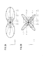
- the above items a) to c) are based on the example of 4-pole coil structure as shown in Figs. 1A, 1C and 2A .
- the above-mentioned 4-pole coil structure is mutually combined and as a result, in the items of b) and c), the electromagnetic field radiation D is more significantly reduced and the electromagnetic field strength r is also more significantly lowered.
- the direction and range in which the electromagnetic field radiation D and the electromagnetic field strength approach zero increase.
- the electromagnetic field radiation D etc. are as described above.
- this non-contact power feeding apparatus 7 by adopting a multi-pole structure, such as the 4-pole structure or the 8-pole structure, with the reverse north and south magnetic poles, the electromagnetic field radiation D is reduced and the electromagnetic field strength r is also lowered as described above.
- a multi-pole structure such as the 4-pole structure or the 8-pole structure
- the electromagnetic waves radiated to the outside show non-directional or isotropic characteristics in the conventional example of this type (refer to Fig. 3C ), while, the electromagnetic waves in the present invention show the specified or limited directional characteristics (refer to Figs. 2A and 2B ). In other words, the externally diffused electric field and magnetic field H are reduced and the strength is also lowered.
- the electromagnetic waves propagated in the vertical (Y) direction and in the lateral (X) direction in a substantially planar manner are drastically reduced in total.
- an electric line of force and a magnetic line of force which are caused and spread peripherally are quantitatively reduced and are qualitatively lowered in strength.
- the electromagnetic waves are as described above.
- the non-contact power feeding apparatus 7 of preferred embodiments of the present invention is constructed as described above. Operation etc. of the embodiments will be described as follows.
- expansion of the air gap G is proportional to the increase of exciting reactive power of the power transmission coil 8 and leads to the increase of exciting apparent power, but its adverse effect can be covered by the above item (9).
- Non-contact power feeding apparatus (Conventional example); 2: Power transmission coil (Conventional example); 3: Power receiving coil (Conventional example); 4: Power feeding side circuit; 5: Power receiving side circuit; 6: Magnetic core; 7: Non-contact power feeding apparatus (Present invention); 8: Power transmission coil (Present invention); 8': Unit coil; 9: Power receiving coil (Present invention); 9': Unit coil; 10: Battery; 11: Load; 12: Power source; 13: Choke coil; 14: Capacitor; 15: Capacitor; 16: Motor; 17: Converter; 18: Inverter; 19: Capacitor; A: Ground; B: Vehicle; C: Power feeding stand; D: Electromagnetic field radiation; G: Air gap; H: Magnetic field; I: Direction of electric current; J: Distance; N: North pole; S: South pole; h: Direction of magnetic field; r: Electromagnetic field strength
Landscapes
- Engineering & Computer Science (AREA)
- Computer Networks & Wireless Communication (AREA)
- Power Engineering (AREA)
- Physics & Mathematics (AREA)
- Electromagnetism (AREA)
- Current-Collector Devices For Electrically Propelled Vehicles (AREA)
- Electric Propulsion And Braking For Vehicles (AREA)
Applications Claiming Priority (1)
| Application Number | Priority Date | Filing Date | Title |
|---|---|---|---|
| JP2010282964A JP5075973B2 (ja) | 2010-12-20 | 2010-12-20 | 多極コイル構造の非接触給電装置 |
Publications (1)
| Publication Number | Publication Date |
|---|---|
| EP2466716A2 true EP2466716A2 (de) | 2012-06-20 |
Family
ID=44651367
Family Applications (1)
| Application Number | Title | Priority Date | Filing Date |
|---|---|---|---|
| EP11181661A Withdrawn EP2466716A2 (de) | 2010-12-20 | 2011-09-16 | Kontaktlose Stromzuführungsvorrichtung |
Country Status (4)
| Country | Link |
|---|---|
| US (1) | US20120153741A1 (de) |
| EP (1) | EP2466716A2 (de) |
| JP (1) | JP5075973B2 (de) |
| CN (1) | CN102545393A (de) |
Cited By (3)
| Publication number | Priority date | Publication date | Assignee | Title |
|---|---|---|---|---|
| WO2014139606A1 (de) * | 2013-03-12 | 2014-09-18 | Paul Vahle Gmbh & Co. Kg | Sekundärseitige spulenanordnung zur induktiven energieübertragung mit quadrupolen |
| WO2014139605A1 (de) * | 2013-03-12 | 2014-09-18 | Paul Vahle Gmbh & Co. Kg | Primärseitige spulenanordnung zur induktiven energieübertragung mit quadrupolen |
| WO2015084555A1 (en) * | 2013-12-02 | 2015-06-11 | Qualcomm Incorporated | Wireless power orthogonal polarization antenna array |
Families Citing this family (14)
| Publication number | Priority date | Publication date | Assignee | Title |
|---|---|---|---|---|
| US20130062966A1 (en) | 2011-09-12 | 2013-03-14 | Witricity Corporation | Reconfigurable control architectures and algorithms for electric vehicle wireless energy transfer systems |
| JP2015508987A (ja) * | 2012-01-26 | 2015-03-23 | ワイトリシティ コーポレーションWitricity Corporation | 減少した場を有する無線エネルギー伝送 |
| JP6083310B2 (ja) * | 2013-04-15 | 2017-02-22 | 日産自動車株式会社 | 非接触給電装置及びその制御方法 |
| JP6162609B2 (ja) * | 2014-01-07 | 2017-07-12 | 昭和飛行機工業株式会社 | 非接触給電装置 |
| JP6299320B2 (ja) * | 2014-03-25 | 2018-03-28 | Tdk株式会社 | コイルユニットおよびワイヤレス電力伝送装置 |
| JP6303684B2 (ja) * | 2014-03-25 | 2018-04-04 | Tdk株式会社 | コイルユニットおよびワイヤレス電力伝送装置 |
| JP6323192B2 (ja) * | 2014-06-12 | 2018-05-16 | 株式会社デンソー | 電力伝送用パッド配置構造および非接触電力伝送システム |
| JP2016005393A (ja) * | 2014-06-18 | 2016-01-12 | Tdk株式会社 | 非接触給電システム |
| JP6374311B2 (ja) * | 2014-12-09 | 2018-08-15 | デクセリアルズ株式会社 | アンテナ装置及び電子機器 |
| GB2537827A (en) * | 2015-04-23 | 2016-11-02 | Bombardier Transp Gmbh | A circuit arrangement and a method of operating a circuit arrangement for a system for inductive power transfer |
| JP6332252B2 (ja) * | 2015-12-09 | 2018-05-30 | トヨタ自動車株式会社 | 受電装置および送電装置 |
| JP6599265B2 (ja) * | 2016-03-01 | 2019-10-30 | 昭和飛行機工業株式会社 | 非接触給電装置 |
| US11374427B2 (en) | 2016-11-01 | 2022-06-28 | Tdk Corporation | Portable electronic device and wireless electric power transmission device |
| JP2018102041A (ja) * | 2016-12-20 | 2018-06-28 | マクセル株式会社 | 非接触送電装置および非接触受電装置 |
Citations (2)
| Publication number | Priority date | Publication date | Assignee | Title |
|---|---|---|---|---|
| JP2008087733A (ja) | 2006-10-05 | 2008-04-17 | Showa Aircraft Ind Co Ltd | 非接触給電装置 |
| JP2010035300A (ja) | 2008-07-28 | 2010-02-12 | Showa Aircraft Ind Co Ltd | 非接触給電装置 |
Family Cites Families (10)
| Publication number | Priority date | Publication date | Assignee | Title |
|---|---|---|---|---|
| JPH1195922A (ja) * | 1997-09-22 | 1999-04-09 | Tokin Corp | マウスパッド、コードレスマウス、およびそれらの組み合わせ |
| DE19746919A1 (de) * | 1997-10-24 | 1999-05-06 | Daimler Chrysler Ag | Elektrische Übertragungsvorrichtung |
| TW462131B (en) * | 1998-07-08 | 2001-11-01 | Winbond Electronics Corp | Assembling type inductive devices |
| JP2003045731A (ja) * | 2001-07-30 | 2003-02-14 | Nec Tokin Corp | 非接触電力伝送装置 |
| WO2003105308A1 (en) * | 2002-01-11 | 2003-12-18 | City University Of Hong Kong | Planar inductive battery charger |
| JP2004047701A (ja) * | 2002-07-11 | 2004-02-12 | Jfe Steel Kk | 非接触充電器用平面磁気素子 |
| US7907043B2 (en) * | 2005-11-30 | 2011-03-15 | Ryutaro Mori | Planar inductor |
| JP4235955B2 (ja) * | 2007-01-12 | 2009-03-11 | 村田機械株式会社 | 非接触給電システムとこれを用いた走行車システム |
| JP4649430B2 (ja) * | 2007-03-20 | 2011-03-09 | セイコーエプソン株式会社 | 非接触電力伝送装置 |
| CN101734172B (zh) * | 2009-12-31 | 2011-12-21 | 西南交通大学 | 一种能够补偿齿槽效应的磁浮列车悬浮间距传感器 |
-
2010
- 2010-12-20 JP JP2010282964A patent/JP5075973B2/ja active Active
-
2011
- 2011-08-10 US US13/206,672 patent/US20120153741A1/en not_active Abandoned
- 2011-08-16 CN CN2011102519156A patent/CN102545393A/zh active Pending
- 2011-09-16 EP EP11181661A patent/EP2466716A2/de not_active Withdrawn
Patent Citations (2)
| Publication number | Priority date | Publication date | Assignee | Title |
|---|---|---|---|---|
| JP2008087733A (ja) | 2006-10-05 | 2008-04-17 | Showa Aircraft Ind Co Ltd | 非接触給電装置 |
| JP2010035300A (ja) | 2008-07-28 | 2010-02-12 | Showa Aircraft Ind Co Ltd | 非接触給電装置 |
Cited By (5)
| Publication number | Priority date | Publication date | Assignee | Title |
|---|---|---|---|---|
| WO2014139606A1 (de) * | 2013-03-12 | 2014-09-18 | Paul Vahle Gmbh & Co. Kg | Sekundärseitige spulenanordnung zur induktiven energieübertragung mit quadrupolen |
| WO2014139605A1 (de) * | 2013-03-12 | 2014-09-18 | Paul Vahle Gmbh & Co. Kg | Primärseitige spulenanordnung zur induktiven energieübertragung mit quadrupolen |
| CN105122399A (zh) * | 2013-03-12 | 2015-12-02 | 保罗·瓦尔有限公司和两合公司 | 用于通过四极子感应式地传输能量的次级侧的线圈装置 |
| WO2015084555A1 (en) * | 2013-12-02 | 2015-06-11 | Qualcomm Incorporated | Wireless power orthogonal polarization antenna array |
| US9153998B2 (en) | 2013-12-02 | 2015-10-06 | Qualcomm Incorporated | Wireless power orthogonal polarization antenna array |
Also Published As
| Publication number | Publication date |
|---|---|
| JP5075973B2 (ja) | 2012-11-21 |
| US20120153741A1 (en) | 2012-06-21 |
| JP2012134217A (ja) | 2012-07-12 |
| CN102545393A (zh) | 2012-07-04 |
Similar Documents
| Publication | Publication Date | Title |
|---|---|---|
| EP2466716A2 (de) | Kontaktlose Stromzuführungsvorrichtung | |
| EP2394840A2 (de) | Kontaktlose Stromzuführungsvorrichtung | |
| EP2601723B1 (de) | Induktive stromempfangsvorrichtung | |
| KR101230211B1 (ko) | 자계 공명 방식의 비접촉 급전장치 | |
| JP5437650B2 (ja) | 非接触給電装置 | |
| US20150091518A1 (en) | Charging configuration for the inductive wireless emission of energy | |
| EP2375533A2 (de) | Mobile kontaktlose Stromzuführvorrichtung | |
| WO2014069445A1 (ja) | 電力伝送システム | |
| CN105109359A (zh) | 感应式电力传输设备 | |
| JP6003565B2 (ja) | 非接触給電装置 | |
| JP5957976B2 (ja) | 非接触給電装置 | |
| EP3363032B1 (de) | Spannungs- und stromkompensation in einer induktiven leistungsübertragungseinheit | |
| EP2903134A1 (de) | Kraftübertragungssystem | |
| EP2587629A1 (de) | Kontaktlose stromzuführungsvorrichtung | |
| JP2010035300A (ja) | 非接触給電装置 | |
| JP2014053984A (ja) | 移動給電式の非接触給電装置 | |
| US11001156B2 (en) | Charging device having an induction coil stitched to a surface of a cross-laid structure | |
| JP2013214613A (ja) | コイルユニット及びコイルユニットを備える電力伝送装置 | |
| JP6537071B2 (ja) | 外部消磁式の非接触給電装置 | |
| JP6162609B2 (ja) | 非接触給電装置 | |
| CN107251174B (zh) | 用于感应式功率传输的系统的功率传输单元、制造及操作功率传输单元的方法 | |
| JP2013207479A (ja) | アンテナ | |
| JP2014093797A (ja) | 電力伝送システム | |
| US20240029948A1 (en) | Ferrite wings systems and methods for inductive wireless power transfer | |
| CN117337530A (zh) | 无芯平面线圈和电力变压器 |
Legal Events
| Date | Code | Title | Description |
|---|---|---|---|
| PUAI | Public reference made under article 153(3) epc to a published international application that has entered the european phase |
Free format text: ORIGINAL CODE: 0009012 |
|
| AK | Designated contracting states |
Kind code of ref document: A2 Designated state(s): AL AT BE BG CH CY CZ DE DK EE ES FI FR GB GR HR HU IE IS IT LI LT LU LV MC MK MT NL NO PL PT RO RS SE SI SK SM TR |
|
| AX | Request for extension of the european patent |
Extension state: BA ME |
|
| STAA | Information on the status of an ep patent application or granted ep patent |
Free format text: STATUS: THE APPLICATION IS DEEMED TO BE WITHDRAWN |
|
| 18D | Application deemed to be withdrawn |
Effective date: 20140401 |