EP2394840A2 - Kontaktlose Stromzuführungsvorrichtung - Google Patents
Kontaktlose Stromzuführungsvorrichtung Download PDFInfo
- Publication number
- EP2394840A2 EP2394840A2 EP11167511A EP11167511A EP2394840A2 EP 2394840 A2 EP2394840 A2 EP 2394840A2 EP 11167511 A EP11167511 A EP 11167511A EP 11167511 A EP11167511 A EP 11167511A EP 2394840 A2 EP2394840 A2 EP 2394840A2
- Authority
- EP
- European Patent Office
- Prior art keywords
- coil
- power
- feeding device
- power feeding
- power receiving
- Prior art date
- Legal status (The legal status is an assumption and is not a legal conclusion. Google has not performed a legal analysis and makes no representation as to the accuracy of the status listed.)
- Withdrawn
Links
Images

Classifications
-
- H—ELECTRICITY
- H02—GENERATION; CONVERSION OR DISTRIBUTION OF ELECTRIC POWER
- H02J—ELECTRIC POWER NETWORKS; CIRCUIT ARRANGEMENTS OR SYSTEMS FOR SUPPLYING OR DISTRIBUTING ELECTRIC POWER; SYSTEMS FOR STORING ELECTRIC ENERGY
- H02J50/00—Circuit arrangements or systems for wireless supply or distribution of electric power
- H02J50/10—Circuit arrangements or systems for wireless supply or distribution of electric power using inductive coupling
- H02J50/12—Circuit arrangements or systems for wireless supply or distribution of electric power using inductive coupling of the resonant type
-
- B—PERFORMING OPERATIONS; TRANSPORTING
- B60—VEHICLES IN GENERAL
- B60L—PROPULSION OF ELECTRICALLY-PROPELLED VEHICLES; SUPPLYING ELECTRIC POWER FOR AUXILIARY EQUIPMENT OF ELECTRICALLY-PROPELLED VEHICLES; ELECTRODYNAMIC BRAKE SYSTEMS FOR VEHICLES IN GENERAL; MAGNETIC SUSPENSION OR LEVITATION FOR VEHICLES; MONITORING OPERATING VARIABLES OF ELECTRICALLY-PROPELLED VEHICLES; ELECTRIC SAFETY DEVICES FOR ELECTRICALLY-PROPELLED VEHICLES
- B60L53/00—Methods of charging batteries, specially adapted for electric vehicles; Charging stations or on-board charging equipment therefor; Exchange of energy storage elements in electric vehicles
- B60L53/10—Methods of charging batteries, specially adapted for electric vehicles; Charging stations or on-board charging equipment therefor; Exchange of energy storage elements in electric vehicles characterised by the energy transfer between the charging station and the vehicle
- B60L53/12—Inductive energy transfer
- B60L53/122—Circuits or methods for driving the primary coil, e.g. supplying electric power to the coil
-
- H—ELECTRICITY
- H01—ELECTRIC ELEMENTS
- H01F—MAGNETS; INDUCTANCES; TRANSFORMERS; SELECTION OF MATERIALS FOR THEIR MAGNETIC PROPERTIES
- H01F38/00—Adaptations of transformers or inductances for specific applications or functions
- H01F38/14—Inductive couplings
-
- B—PERFORMING OPERATIONS; TRANSPORTING
- B60—VEHICLES IN GENERAL
- B60L—PROPULSION OF ELECTRICALLY-PROPELLED VEHICLES; SUPPLYING ELECTRIC POWER FOR AUXILIARY EQUIPMENT OF ELECTRICALLY-PROPELLED VEHICLES; ELECTRODYNAMIC BRAKE SYSTEMS FOR VEHICLES IN GENERAL; MAGNETIC SUSPENSION OR LEVITATION FOR VEHICLES; MONITORING OPERATING VARIABLES OF ELECTRICALLY-PROPELLED VEHICLES; ELECTRIC SAFETY DEVICES FOR ELECTRICALLY-PROPELLED VEHICLES
- B60L2200/00—Type of vehicles
- B60L2200/26—Rail vehicles
-
- Y—GENERAL TAGGING OF NEW TECHNOLOGICAL DEVELOPMENTS; GENERAL TAGGING OF CROSS-SECTIONAL TECHNOLOGIES SPANNING OVER SEVERAL SECTIONS OF THE IPC; TECHNICAL SUBJECTS COVERED BY FORMER USPC CROSS-REFERENCE ART COLLECTIONS [XRACs] AND DIGESTS
- Y02—TECHNOLOGIES OR APPLICATIONS FOR MITIGATION OR ADAPTATION AGAINST CLIMATE CHANGE
- Y02T—CLIMATE CHANGE MITIGATION TECHNOLOGIES RELATED TO TRANSPORTATION
- Y02T10/00—Road transport of goods or passengers
- Y02T10/60—Other road transportation technologies with climate change mitigation effect
- Y02T10/70—Energy storage systems for electromobility, e.g. batteries
-
- Y—GENERAL TAGGING OF NEW TECHNOLOGICAL DEVELOPMENTS; GENERAL TAGGING OF CROSS-SECTIONAL TECHNOLOGIES SPANNING OVER SEVERAL SECTIONS OF THE IPC; TECHNICAL SUBJECTS COVERED BY FORMER USPC CROSS-REFERENCE ART COLLECTIONS [XRACs] AND DIGESTS
- Y02—TECHNOLOGIES OR APPLICATIONS FOR MITIGATION OR ADAPTATION AGAINST CLIMATE CHANGE
- Y02T—CLIMATE CHANGE MITIGATION TECHNOLOGIES RELATED TO TRANSPORTATION
- Y02T10/00—Road transport of goods or passengers
- Y02T10/60—Other road transportation technologies with climate change mitigation effect
- Y02T10/7072—Electromobility specific charging systems or methods for batteries, ultracapacitors, supercapacitors or double-layer capacitors
-
- Y—GENERAL TAGGING OF NEW TECHNOLOGICAL DEVELOPMENTS; GENERAL TAGGING OF CROSS-SECTIONAL TECHNOLOGIES SPANNING OVER SEVERAL SECTIONS OF THE IPC; TECHNICAL SUBJECTS COVERED BY FORMER USPC CROSS-REFERENCE ART COLLECTIONS [XRACs] AND DIGESTS
- Y02—TECHNOLOGIES OR APPLICATIONS FOR MITIGATION OR ADAPTATION AGAINST CLIMATE CHANGE
- Y02T—CLIMATE CHANGE MITIGATION TECHNOLOGIES RELATED TO TRANSPORTATION
- Y02T90/00—Enabling technologies or technologies with a potential or indirect contribution to GHG emissions mitigation
- Y02T90/10—Technologies relating to charging of electric vehicles
- Y02T90/12—Electric charging stations
-
- Y—GENERAL TAGGING OF NEW TECHNOLOGICAL DEVELOPMENTS; GENERAL TAGGING OF CROSS-SECTIONAL TECHNOLOGIES SPANNING OVER SEVERAL SECTIONS OF THE IPC; TECHNICAL SUBJECTS COVERED BY FORMER USPC CROSS-REFERENCE ART COLLECTIONS [XRACs] AND DIGESTS
- Y02—TECHNOLOGIES OR APPLICATIONS FOR MITIGATION OR ADAPTATION AGAINST CLIMATE CHANGE
- Y02T—CLIMATE CHANGE MITIGATION TECHNOLOGIES RELATED TO TRANSPORTATION
- Y02T90/00—Enabling technologies or technologies with a potential or indirect contribution to GHG emissions mitigation
- Y02T90/10—Technologies relating to charging of electric vehicles
- Y02T90/14—Plug-in electric vehicles
Definitions
- the present invention relates to a non-contact power feeding device, and more particularly to a non-contact power feeding device adapted to feed power, with no contact, to a power receiving side which is mounted on a vehicle and the like from a power feeding side which is fixedly disposed on the ground side.
- a non-contact power feeding device adapted to feed power from outside to, for example, a battery of an electric vehicle without any mechanical contact such as a cable has been developed based on the remand and this device is in practical use.
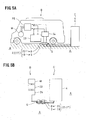
- a non-contact power feeding device power is fed through an air gap of about tens of millimeters to hundreds of millimeters to a power receiving coil mounted on an electric vehicle or other vehicle from a power transmission coil which is fixedly disposed on the ground side, based on a mutual induction effect of electromagnetic induction (refer to Fig. 5 described below).
- the power transmission coil 3 is caused to face the power receiving coil 8 through an air gap G.
- a magnetic flux is then formed at the power transmission coil 3 to which an exciting current is applied, to generate an induced electromotive force at the power receiving coil 8, thereby feeding power to the power receiving side circuit 7 from the power feeding side circuit 2.
- an exciting reactive power is fed to a magnetic path of the air gap G by the resonance to expand the air gap G and to increase the power supply quantity.
- Reference numeral 11 in Fig. 4A is a choke coil, 12. is a circuit resistance, and 13 and 14 are coil resistances.
- Patent Documents 1 and 2 Examples of such a non-contact power feeding device 1 are disclosed in the following Patent Documents 1 and 2.
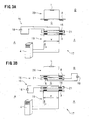
- a non-contact power feeding device 17 according to this prior application is characterized in that, as shown in Figs. 3A and 3B , a resonant coil 16 of a repeating circuit 15 is disposed on the power transmission coil 3 side and/or the power receiving coil 8 side.
- the non-contact power feeding device 17 is provided with the independent repeating circuit 15 as a resonance circuit.
- the repeating circuit 15 is provided in such a manner that the resonant coil 16 adapted to resonate with a capacitor 18 is disposed in a magnetic path of the air gap G.
- Reference numeral 21 of Figs. 3A and 3B is a molded resin.
- the non-contact power feeding device 17 of the prior application as shown in Figs. 3A and 3B has an extremely beneficial effect described above, but it has been pointed out that there is a problem in the coil thickness.
- the non-contact power feeding device 17 a comparatively thin coil of a flat structure is adopted for the power transmission coil 3, the power receiving coil 8, the resonant coil 16 and the like.
- a comparatively thin coil of a flat structure is adopted for the power transmission coil 3, the power receiving coil 8, the resonant coil 16 and the like.
- the power transmission coil 3 and the resonant coil 16 and the power receiving coil 8 and the resonant coil 16 are disposed to overlap each other in the magnetic path and as a result, the coil is made thick in total.
- the resonant coil 16 is disposed to overlap in the magnetic path of the power transmission coil 3.
- a space for encasing both coils 3, 16 in concrete and holding them is made large and gains weight as well. Accordingly, it has been pointed out that it is not easy to dispose the non-contact power feeding device 17 on the ground A side.
- the resonant coil 16 is disposed to overlap in the magnetic path of the power receiving coil 8 and as a result, a space for installing both coils 8, 16 under a floor surface and the like is made bulky and gains weight as well.
- it has been pointed out that it is not easy to dispose the non-contact power feeding device 17 on the side of vehicle B and the like.
- a non-contact power feeding device of the present invention was developed to solve the problems of the non-contact power feeding device 17 of the prior application.
- a non-contact power feeding device in which power is fed through an air gap with no contact from a power transmission coil of a power feeding side circuit .to a power receiving coil of a power receiving side circuit, which are located to face each other, based on a mutual induction effect of electromagnetic induction.
- a resonant coil of a repeating circuit is disposed on the power transmission coil side and/or the power receiving coil side, and the resonant coil is wound in parallel on the same plane as the power transmission coil and/or the power receiving coil.
- the non-contact power feeding device according to the present invention can be modified by adding technically limited elements.
- the repeating circuit is independent of the power feeding side circuit and the power receiving side circuit, and the resonant coil is provided to resonate with a capacitor disposed in the repeating circuit to feed the exciting reactive power to a magnetic path.
- the resonant coil and the power transmission coil are provided in such a manner that each insulated coil conducting wire is spirally wound more than once in a concentric pattern while maintaining the parallel positional relationship on the same plane whereby each insulated coil conducting wire is mutually disposed in parallel, and the resonant coil and the power transmission coil are formed in a flat structure as a whole.
- the power feeding side circuit such as the power transmission coil is fixedly disposed on the ground side, while the power receiving side circuit such as the power receiving coil is mounted on a vehicle or other movable body.
- the resonant coil, the power transmission coil and the power receiving coil are respectively composed of a single insulated coil conducting wire or a number of insulated coil conducting wires.
- the resonant coil and the power receiving coil are provided in such a manner that each insulated coil conducting wire is spirally wound more than once in a concentric pattern while maintaining the parallel positional relationship on the same plane whereby each insulated coil conducting wire is mutually disposed in parallel, and the resonant coil and the power receiving coil are formed in a flat structure as a whole.
- the power feeding side circuit such as the power transmission coil is fixedly disposed on the ground side, while the power receiving side circuit such as the power receiving coil is mounted on a vehicle or other movable body.
- the resonant coil, the power transmission coil and the power receiving coil are respectively composed of a single insulated coil conducting wire or a number of insulated coil conducting wires.
- a coil can be made thin.
- the non-contact power feeding device of the present invention is provided in such a manner that a resonant coil is wound in parallel on the same plane as a power transmission coil and/or a power receiving coil.
- the resonant coil is disposed on the same plane as the power transmission coil on the ground side, for example, on the side of a road surface, the coil can be made thin in total as compared to the above-described non-contact power feeding device of the prior application in which both coils are disposed to overlap in the magnetic path. Accordingly, a space for totally encasing both coils in concrete and the like and holding them can be made thin and the weight can also be reduced accordingly. Thus, disposition of the non-contact power feeding device on the ground side can be readily realized.
- the resonant coil is disposed on the same plane as the power receiving coil on the side of a vehicle and the like, for example, on the floor surface side of the vehicle, the coil can be made thin in total as compared to the above-described non-contact power feeding device of the prior application in which both coils are disposed to overlap in the magnetic path. In this manner, a space for installing the non-contact power feeding device under the floor surface and the like can be made small and the weight can also be reduced accordingly. Thus, disposition of the non-contact power feeding device of the present invention on vehicle side and the like can be readily realized.
- this (reduction of the coil thickness) can be realized with a high coupling coefficient, a large air gap and a large amount of power supply.
- the non-contact power feeding device is provided in such a manner that the resonant coil is disposed with the power transmission coil and/or the power receiving coil.
- the electromagnetic coupling between the power transmission coil of the power feeding side circuit and the power receiving coil of the power receiving side circuit is further strengthened. As a result, a higher coupling coefficient is obtained to provide an excellent power feeding efficiency.
- this non-contact power feeding device of the present invention it is therefore possible to feed a large amount of power over a larger gap as compared to the conventional non-contact power feeding device of this type described above.
- the above-described first and second effects can be readily realized with a simple structure whereby the resonant coil is wound in parallel on the same plane as the power transmission coil and/or the power receiving coil.
- the non-contact power feeding device of the present invention the resonant coil and the power transmission coil and/or the resonant coil and the power receiving coil are united (integrated) without being overlapped as a separate body in the magnetic path.
- the non-contact power feeding device of the present invention is excellent in cost in view of the fact that molded resin, other associated members and parts are reduced and production is simplified.
- a structure of the power receiving side circuit is not only simplified, but also a predetermined coupling coefficient can be obtained without a resonant capacitor.
- cost on the vehicle side and the like can be reduced as compared to the conventional example of this type. In this manner, it has a great advantage that cost reduction can be realized on the vehicle side and the like which requires more parts than the ground side.
- the present invention has prominent effects in that all the problems of the conventional example of this kind can be solved with the first, second and third effects.
- a non-contact power feeding device 22 of the present invention (the non-contact power feeding device 17 of prior application) is generally described with reference to Figs. 5A and 5B .
- the non-contact power feeding device 22 (17) is provided in such a manner that electric power is fed, through (over) an air gap G with no contact, from a power transmission coil 3 of a power feeding side circuit 19 to a power receiving coil 8 of a power receiving side circuit 20, which are closely located to face each other, based on a mutual induction effect of the electromagnetic induction.
- the power feeding side circuit 19 is fixedly disposed on the side of ground A, while the power receiving side circuit 20 is mounted on a movable body such as a vehicle B side.
- the power feeding side circuit 19 on the primary side that is, the track side, is fixedly disposed on a ground surface, a road surface, a floor surface or other side of ground A at a power feeding stand C or in other power feeding area.
- the power receiving side circuit 20 on the secondary side that is, the pickup side is mounted on the vehicle B such as an electric vehicle or an electric train, or other movable body.
- the power receiving side circuit 20 is not only available for driving, but also for non-driving and as shown in Figs. 5A and 5B , it is usually connected to a car-mounted battery 23.
- the power receiving side circuit 20 can also be connected direct to various types of loads L.
- the power transmission coil 3 of the power feeding side circuit 19 and the power receiving coil 8 of the power receiving side circuit 20 are closely located to face each other with no contact through an air gap G which is a small space of, for example, about 50mm to i.50mm.
- power feeding is typically effected by a stopped power feeding method whereby the power receiving coil 8 is stopped over the power transmission coil 3.
- the power transmission coil 3 and the power receiving coil 8 are provided in a vertically symmetric structure.
- the power transmission coil 3 of the power feeding side circuit 2 is connected to a power source 4 in which a high frequency inverter is used.
- the power receiving coil 8 of the power receiving side circuit 20 can be connected to a battery 23 in the example as shown in Figs. 5A and 5B , wherein a running motor M is driven by the battery 23 charged by a power feeding operation.
- Reference numeral 24 of Figs. 5A and 5B is a converter for converting an alternating current to a direct current and 25 is an inverter for converting the direct current to the alternating current.
- the power transmission coil 3 and the power receiving coil 8 are ' respectively composed of a substantially flat structure whereby an insulated coil conducting wire is wound more than once (a number of times).
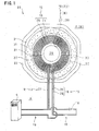
- the power transmission coil 3 and the power receiving coil 8 are respectively formed in a thin flat structure of a circular, that is, substantially flange shape as a whole in which each insulated coil conducting wire is spirally wound more than once in a circular or rectangular shape while maintaining the parallel positional relationship in which, for example, a number of insulated conducting wires are disposed in parallel on the same plane (refer to Fig. 1 described later).
- a high frequency alternating current of, for example, about 10 kHz to 100 kHz to the power transmission coil 3 of the power feeding side circuit 19 from the power source 4 as an exciting current a magnetic field is generated around the coil conducting wire of the power transmission coil 3 to form a magnetic flux in the direction perpendicular to the coil surface.
- the magnetic flux formed in this way goes through the power receiving coil 8 of the power receiving side circuit 20 to generate the induced electromotive force, thereby forming the magnetic field, wherein the electric power is fed and received using the magnetic field formed.
- the power transmission coil 3 of the power feeding side circuit 19 and the power receiving coil 8 of the power receiving side circuit 20 are electromagnetically coupled through the air gap G where a magnetic path of a magnetic flux is formed.
- power of several kW or more, for example, tens of kW to hundreds of kW can be fed.
- the non-contact power feeding device 22 is as generally described above.
- Non-contact power feeding device 17 of Figs. 3A and 3B Non-contact power feeding device 17 of Figs. 3A and 3B
- a non-contact power feeding device 17 of the above-described prior application which becomes the premise of the present invention will be described below.
- the non-contact power feeding device 17 is provided in such a manner that a resonant coil 16 of a repeating circuit 15 is disposed on the power transmission coil 3 side and/or the power receiving coil 8 side (refer to Figs. 3A and 3B ).
- the repeating circuit 15 is a circuit which is independent of the power feeding side circuit 19 and the power receiving side circuit 20 and is a (resonant) circuit adapted to resonate in a resonant frequency matching an operating frequency of the power source 4.
- the repeating circuit 15 is provided in such a manner that the resonant coil 16 adapted to resonate with a capacitor 18 is the disposed in a magnetic path of the air gap G between the power transmission coil 3 and the power receiving coil 8.
- the power transmission coil 3 and the resonant coil 16, and the power receiving coil 8 and the resonant coil 16 are respectively formed in a flat structure (refer to the above description for the flat structure).
- the power transmission coil 3 and/or the power receiving coil 8 have a positional relationship in which the resonant coil 16 is disposed to overlap in the magnetic path.
- the non-contact power feeding device 17 is provided with the resonant coil 16.
- the resonant coil 16 feeds the exciting reactive power (i.e., the product of the exciting current and the counter-electromotive force generated in the magnetic flux) to the magnetic path of the magnetic flux between the power transmission coil 3 and the power receiving coil 8.
- the non-contact power feeding device 17 makes it possible to increase the exciting reactive power without making the power feeding side circuit 19 and the power receiving side circuit 20 large-current and/or high-voltage (Only the repeating circuit 15 is made large-current and/or high-voltage).
- the non-contact power feeding device 17 makes it possible to generate the magnetic flux necessary to feed a large amount of power over the large air gap G in the magnetic path. Based on this, improvement of the coupling coefficient, expansion of the air gap G, feeding of a large amount of power, and the like can be achieved.
- the repeating circuit 15 provided with such a resonant coil 16 is disposed only on the power transmission coil 3 side, that is, on the ground A side, of the power feeding side circuit 19.
- the repeating circuit 15 provided with the resonant coil 16 is disposed only on the power receiving coil 8 side of the power receiving side circuit 20, that is, only on each vehicle B side.
- the repeating circuit 15 provided with the resonant coil 16 is disposed on both the power transmission coil 3 side of the power feeding side circuit 19 and the power receiving coil 8 side of the power receiving side circuit 20.
- the improvement of the coupling coefficient, expansion of the air gap G, feeding of a large amount of power, and the like can be further promoted.
- the non-contact power feeding device 17 of Fig. 3 serving as the premise of the present invention is as described above.
- a non-contact power feeding device 22 of an embodiment of the present invention will now be described with reference to Figs. 1 and 2A . First, an outline of the embodiment will be described.
- a resonant coil 16 of a repeating circuit 15 is disposed on a power transmission coil 3 side of a power feeding side circuit 19 and/or a power receiving coil 8 side of a power receiving side circuit 20.
- the resonant coil 16 is wound in parallel on the same plane as the power transmission coil 3 and the power receiving coil 8.
- the resonant coil 16, the power transmission coil 3 and the power receiving coil 8 are respectively composed of a single insulated coil conducting wire or a number of insulated coil conducting wires (26, 27 and 28).
- the non-contact power feeding device 22 will now be described in detail with reference to Figs. 1 and 2A .
- the positional relationship of the resonant coil 16 and the like is as follows. In the example as shown in Fig. 1 , the resonant coil 16 and the power transmission coil 3 are wound in parallel on the same plane.
- One unit of insulated coil conducting wire 26 constituting the resonant coil 16 and one unit of insulated coil conducting wire 27 constituting the power transmission coil 3 are spirally wound a number of times in a concentric manner to be circular or rectangular shape while maintaining a parallel positional relationship in which the insulated coil conducting wires are internally and externally disposed in parallel on the same plane.
- the resonant coil 16 and the power transmission coil 3 are integrally and flatly gathered to provide a thin flat structure as a whole.
- the resonant coil 16 and the power transmission coil 3 are provided with a central open space 29 in the center to provide a circular shape, that is, a substantially flange shape.
- a ferromagnetic body such as a ferrite core 30 is used as a magnetic core for the power transmission coil 3.
- the ferromagnetic body is formed in a flat circular shape, that is, a substantially flange shape and is disposed in the same concentric pattern as the power transmission coil 3.
- FIG. 1 shows an example in which the resonant coil 16 and the power receiving coil 8 are wound in parallel on the same plane.
- one unit of insulated coil conducting wire 26 constituting the resonant coil 16 and one unit of insulated coil conducting wire 28 constituting the power receiving coil 8 are spirally wound more than once (a number of times) in a concentric pattern while maintaining the parallel positional relationship in which the insulated coil conducting coils are disposed in parallel internally and externally on the same plane.
- the resonant coil 16 and the power receiving coil 8 are respectively formed in a flat structure as a whole.
- Their detailed structures conform to those of the resonant coil 16 and the power transmission coil 3 described above.
- the number of the insulated coil conducting wires 26 constituting the resonant coil 16, the number of the insulated coil conducting wires 27 constituting the power transmission coil 3, and the number of insulated coil conducting wires 28 constituting the power receiving coil 8 can be singular or plural.
- the resonant coil 16, the power transmission coil 3 and the power receiving coil 8 are respectively composed of a single insulated coil conducting wire or a number of insulated coil conducting wires (26, 27 and 28).
- the resonant coil 16 is provided so that two insulated coil conducting wires 26 are formed as one unit, while the power transmission coil 3 (the power receiving coil 8) is provided so that one insulated coil conducting wire 27 (the insulated coil conducting wire 28) is formed as one unit.
- the power transmission coil 3 the power receiving coil 8
- one insulated coil conducting wire 27 the insulated coil conducting wire 28
- a winding method is as follows. First, for the resonant coil 16 and the power transmission coil 3 (or the power receiving coil 8), a method is considered whereby both insulated coil conducting wires 26 and 27 (or 28) are aligned together to rewind from inside to outside, in order, from the central section.
- both insulated coil conducting wires 26 and 27 (or 28) are first separately rewound with a groove space to mutually fit both wires into the groove space.
- both wires are first separately rewound for inside or outside (without the groove space described above) with the winding diameter small or large to fit the inside wire into the central open space for the outside wire.
- Reference numeral 31 of Fig. 1 is a molded resin, 32 is a foamed material, and 33 is a base plate. Reference numerals 34 and 35 of Fig. 2A are coil resistance.
- the non-contact power feeding device 22 of the present invention is constructed as described above. Operation etc. of the present invention will now be described in the following items (1) through (9).
- the structure of the non-contact power feeding device 22 can be simplified. Even in comparison to the conventional non-contact power feeding device 1 as shown in Figs. 4A and 4B , a predetermined coupling coefficient can be obtained even though the resonant capacitors 9, 10 are not provided for each power receiving side circuit 7 such as the vehicle B as in the non-contact power feeding device 1. Thus, the structure of the non-contact power feeding device 22 can be simplified even from this point of view.
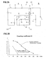
- Fig. 2B is a graph showing the data of each coupling coefficient of an embodiment of the non-contact power feeding device 22 of the present invention as shown in Fig. 2A and the conventional non-contact power feeding device 1 as shown in Figs. 4A and 4B .
- This experimental data was obtained by computing the coupling coefficient K for each spacing size based on the actual measurement value while changing the spacing size of the air gaps G of the non-contact power feeding device 22 and the non-contact power feeding device 1.
- the coupling coefficient K is 0.95 in the case where the air gap G is 50 mm, while the coupling coefficient K is 0.85 in the case where the air gap G is 100 mm. Even in the case where the air gap G is 200 mm, the coupling coefficient K is 0.38 and further, the coupling coefficient K is 0.08 even in the case where the air gap G is 300 mm.
- the coupling coefficient K is 0.2'l in the case where the air gap G is 80 mm and as a result, supply power of 6 kW was obtained on the experiment.
- the coupling coefficient K of 0.6 was obtained in the case where the air gap G is 150 mm and it is possible to obtain the same supply power of 6 kW as in the conventional non-contact power feeding device 1.
- both devices 1, 22 showed the same output power of 6 kW, but in the case of the non-contact power feeding device 22 of the present invention, it is to be noted that the output power of 6 kW has been attained under much larger air gap G and with a small power source 4 output. In this manner, the present invention made it possible to obtain high coupling coefficient K and to feed a large amount of power under a large air gap G.
- the preferred embodiment is as described above.
- Non-contact power feeding device (Conventional example); 2: Power feeding side circuit (Conventional example); 3: Power transmission coil; 4: Power source; 5: Capacitor; 6: Capacitor; 7: Power receiving side circuit (Conventional example); 8: Power receiving coil; 9: Capacitor; 10: Capacitor; 11: Choke coil; 12: Circuit resistance; 13: Coil resistance; 14: Coil resistance; 15: Repeating circuit; 16: Resonant coil; 17: Non-contact power feeding device (Prior application); 18: Capacitor; 19: Power feeding side circuit (Present invention; Prior application); 20: Power receiving side circuit (Present invention; Prior application); 21: Molded resin; 22: Non-contact power feeding device (Present invention); 23: Battery; 24: Converter; 25: Inverter; 26: Coil conducting wire; 27: Coil conducting wire; 28: Coil conducting wire; 29: Central open space; 30: Ferrite core; 31: Molded resin; 32: Foamed material; 33: Base plate; 34:
Landscapes
- Engineering & Computer Science (AREA)
- Power Engineering (AREA)
- Transportation (AREA)
- Mechanical Engineering (AREA)
- Computer Networks & Wireless Communication (AREA)
- Current-Collector Devices For Electrically Propelled Vehicles (AREA)
- Electric Propulsion And Braking For Vehicles (AREA)
- Charge And Discharge Circuits For Batteries Or The Like (AREA)
Applications Claiming Priority (1)
| Application Number | Priority Date | Filing Date | Title |
|---|---|---|---|
| JP2010132986A JP2011258807A (ja) | 2010-06-10 | 2010-06-10 | 非接触給電装置 |
Publications (1)
| Publication Number | Publication Date |
|---|---|
| EP2394840A2 true EP2394840A2 (de) | 2011-12-14 |
Family
ID=44654604
Family Applications (1)
| Application Number | Title | Priority Date | Filing Date |
|---|---|---|---|
| EP11167511A Withdrawn EP2394840A2 (de) | 2010-06-10 | 2011-05-25 | Kontaktlose Stromzuführungsvorrichtung |
Country Status (5)
| Country | Link |
|---|---|
| US (1) | US20110304217A1 (de) |
| EP (1) | EP2394840A2 (de) |
| JP (1) | JP2011258807A (de) |
| KR (1) | KR20110135334A (de) |
| CN (1) | CN102280945A (de) |
Cited By (2)
| Publication number | Priority date | Publication date | Assignee | Title |
|---|---|---|---|---|
| EP2876779A4 (de) * | 2013-07-08 | 2016-03-30 | Nitto Denko Corp | Energieversorger und empfänger sowie mobile vorrichtung |
| EP2760035A4 (de) * | 2012-04-17 | 2016-06-15 | Nitto Denko Corp | Verfahren zur herstellung von magnetfeldräumen |
Families Citing this family (26)
| Publication number | Priority date | Publication date | Assignee | Title |
|---|---|---|---|---|
| US9099885B2 (en) | 2011-06-17 | 2015-08-04 | Semiconductor Energy Laboratory Co., Ltd. | Wireless power feeding system |
| JP5906456B2 (ja) * | 2011-09-15 | 2016-04-20 | パナソニックIpマネジメント株式会社 | 非接触給電システム及び中継器 |
| KR101305790B1 (ko) * | 2012-04-18 | 2013-09-06 | 엘지이노텍 주식회사 | 무선전력 송신장치, 무선전력 수신장치 |
| CN104335452B (zh) | 2012-05-14 | 2017-08-29 | Lg 电子株式会社 | 无线电力传送装置和具有该无线电力传送装置的无线充电系统 |
| US9548621B2 (en) | 2012-05-28 | 2017-01-17 | Panasonic Intellectual Property Management Co., Ltd. | Contactless connector system tolerant of position displacement between transmitter coil and receiver coil and having high transmission efficiency |
| US9466418B2 (en) * | 2012-06-12 | 2016-10-11 | Gerogia Tech Research Corporation | Multi-band and broadband wireless power transfer through embedded geometric configurations |
| US20140083770A1 (en) * | 2012-09-24 | 2014-03-27 | Schlumberger Technology Corporation | System And Method For Wireless Drilling And Non-Rotating Mining Extenders In A Drilling Operation |
| JP2014090528A (ja) | 2012-10-29 | 2014-05-15 | Hitachi Ltd | 移動体用非接触充電装置および移動体用非接触充電方法 |
| JP5924496B2 (ja) * | 2012-10-31 | 2016-05-25 | 株式会社エクォス・リサーチ | 電力伝送システム |
| CN103915681B (zh) * | 2013-01-02 | 2017-05-03 | 瑞声精密制造科技(常州)有限公司 | 天线 |
| PL3074987T3 (pl) * | 2013-11-25 | 2021-12-20 | A K Stamping Co. Inc. | Cewka do ładowania bezprzewodowego |
| CN103647358B (zh) * | 2013-12-18 | 2016-03-30 | 中国科学院电工研究所 | 一种无线能量传输装置的线圈 |
| CN103731327B (zh) * | 2013-12-26 | 2017-03-01 | 浙江天工智能电子有限公司 | 一种区域总线供电与本地无线供电相结合的智能家居系统 |
| JP2015128347A (ja) * | 2013-12-27 | 2015-07-09 | 富士通コンポーネント株式会社 | 無線受電装置、無線送電装置 |
| JP2015142019A (ja) | 2014-01-29 | 2015-08-03 | トヨタ自動車株式会社 | 受電装置 |
| KR102166881B1 (ko) | 2014-04-03 | 2020-10-16 | 엘지이노텍 주식회사 | 무선 전력 송신 장치 |
| KR101634650B1 (ko) | 2015-06-01 | 2016-07-01 | 한국철도기술연구원 | 대전력의 무선 급전을 위한 급집전 코일의 최적화 설계 방법 및 장치 |
| CN108352248A (zh) * | 2015-06-29 | 2018-07-31 | 无线先进车辆电气化有限公司 | 使用多个螺线的匹配绕组的低电感垫绕组 |
| US10439450B2 (en) * | 2016-03-31 | 2019-10-08 | Samsung Electronics Co., Ltd. | Wireless power transmitting device and method for controlling the same |
| US11426091B2 (en) | 2017-09-06 | 2022-08-30 | Apple Inc. | Film coatings as electrically conductive pathways |
| US10381881B2 (en) * | 2017-09-06 | 2019-08-13 | Apple Inc. | Architecture of portable electronic devices with wireless charging receiver systems |
| JP7024312B2 (ja) * | 2017-10-19 | 2022-02-24 | 株式会社Ihi | コイル装置 |
| JP6802607B2 (ja) * | 2017-11-20 | 2020-12-16 | 昭和飛行機工業株式会社 | 非接触給電装置 |
| US11462943B2 (en) | 2018-01-30 | 2022-10-04 | Wireless Advanced Vehicle Electrification, Llc | DC link charging of capacitor in a wireless power transfer pad |
| US11437854B2 (en) | 2018-02-12 | 2022-09-06 | Wireless Advanced Vehicle Electrification, Llc | Variable wireless power transfer system |
| CN112583134B (zh) * | 2020-12-01 | 2022-05-27 | 浙江大学 | 一种可切换无线电能传输线圈与补偿电容的可变电路拓扑 |
Citations (3)
| Publication number | Priority date | Publication date | Assignee | Title |
|---|---|---|---|---|
| JPH07170681A (ja) | 1993-10-21 | 1995-07-04 | Auckland Uniservices Ltd | 誘導電力ピックアップ装置 |
| JP2008087733A (ja) | 2006-10-05 | 2008-04-17 | Showa Aircraft Ind Co Ltd | 非接触給電装置 |
| JP2009019086A (ja) | 2007-07-11 | 2009-01-29 | Toyo Ink Mfg Co Ltd | 難燃性感光性樹脂及びその組成物及びその硬化物及びフォトソルダーレジスト組成物 |
Family Cites Families (12)
| Publication number | Priority date | Publication date | Assignee | Title |
|---|---|---|---|---|
| US3119897A (en) * | 1959-06-16 | 1964-01-28 | Daven Company | Insulated wire for high temperature use and coils made therefrom |
| JP2001283164A (ja) * | 2000-03-31 | 2001-10-12 | Seiko Epson Corp | 送受信システム、送受信装置、リーダライタシステム、応答装置、非接触icカード、ラベルタグ |
| KR20040072581A (ko) * | 2004-07-29 | 2004-08-18 | (주)제이씨 프로텍 | 전자기파 증폭중계기 및 이를 이용한 무선전력변환장치 |
| CN101197507A (zh) * | 2006-12-06 | 2008-06-11 | 北京中电华大电子设计有限责任公司 | 无线电源装置及电路 |
| US9634730B2 (en) * | 2007-07-09 | 2017-04-25 | Qualcomm Incorporated | Wireless energy transfer using coupled antennas |
| US20100045114A1 (en) * | 2008-08-20 | 2010-02-25 | Sample Alanson P | Adaptive wireless power transfer apparatus and method thereof |
| JP4911148B2 (ja) * | 2008-09-02 | 2012-04-04 | ソニー株式会社 | 非接触給電装置 |
| JP2010074937A (ja) * | 2008-09-18 | 2010-04-02 | Toyota Motor Corp | 非接触受電装置およびそれを備える車両 |
| US8421409B2 (en) * | 2008-09-19 | 2013-04-16 | Toyota Jidosha Kabushiki Kaisha | Noncontact power receiving apparatus for electrically-powered vehicle and vehicle including the same |
| JP5476917B2 (ja) * | 2009-10-16 | 2014-04-23 | Tdk株式会社 | ワイヤレス給電装置、ワイヤレス受電装置およびワイヤレス電力伝送システム |
| JP2011142724A (ja) * | 2010-01-06 | 2011-07-21 | Hitachi Ltd | 非接触電力伝送装置及びそのための近接場アンテナ |
| MX2012009085A (es) * | 2010-02-10 | 2012-12-17 | Fujitsu Ltd | Metodo de control de frecuencia resonante, dspositvos de transmision de potencia electrica, dispositivo de recuperacion de potencia electrica en sistema de transmision de potencia tipo resonante magnetico. |
-
2010
- 2010-06-10 JP JP2010132986A patent/JP2011258807A/ja active Pending
-
2011
- 2011-05-25 KR KR1020110049325A patent/KR20110135334A/ko not_active Ceased
- 2011-05-25 EP EP11167511A patent/EP2394840A2/de not_active Withdrawn
- 2011-06-09 US US13/156,955 patent/US20110304217A1/en not_active Abandoned
- 2011-06-09 CN CN2011101620239A patent/CN102280945A/zh active Pending
Patent Citations (3)
| Publication number | Priority date | Publication date | Assignee | Title |
|---|---|---|---|---|
| JPH07170681A (ja) | 1993-10-21 | 1995-07-04 | Auckland Uniservices Ltd | 誘導電力ピックアップ装置 |
| JP2008087733A (ja) | 2006-10-05 | 2008-04-17 | Showa Aircraft Ind Co Ltd | 非接触給電装置 |
| JP2009019086A (ja) | 2007-07-11 | 2009-01-29 | Toyo Ink Mfg Co Ltd | 難燃性感光性樹脂及びその組成物及びその硬化物及びフォトソルダーレジスト組成物 |
Cited By (5)
| Publication number | Priority date | Publication date | Assignee | Title |
|---|---|---|---|---|
| EP2760035A4 (de) * | 2012-04-17 | 2016-06-15 | Nitto Denko Corp | Verfahren zur herstellung von magnetfeldräumen |
| US9892847B2 (en) | 2012-04-17 | 2018-02-13 | Nitto Denko Corporation | Method for forming magnetic field space |
| EP2876779A4 (de) * | 2013-07-08 | 2016-03-30 | Nitto Denko Corp | Energieversorger und empfänger sowie mobile vorrichtung |
| US9325207B2 (en) | 2013-07-08 | 2016-04-26 | Nitto Denko Corporation | Power supplier and receiver and mobile device |
| US9537356B2 (en) | 2013-07-08 | 2017-01-03 | Nitto Denko Corporation | Power supplier and receiver and mobile device |
Also Published As
| Publication number | Publication date |
|---|---|
| CN102280945A (zh) | 2011-12-14 |
| US20110304217A1 (en) | 2011-12-15 |
| JP2011258807A (ja) | 2011-12-22 |
| KR20110135334A (ko) | 2011-12-16 |
Similar Documents
| Publication | Publication Date | Title |
|---|---|---|
| EP2394840A2 (de) | Kontaktlose Stromzuführungsvorrichtung | |
| KR101230211B1 (ko) | 자계 공명 방식의 비접촉 급전장치 | |
| JP5437650B2 (ja) | 非接触給電装置 | |
| JP7194091B2 (ja) | 誘導電力伝達装置 | |
| US10340078B2 (en) | Coil topologies for inductive power transfer | |
| US11251661B2 (en) | Inductive power transmitter | |
| US20120153741A1 (en) | Non-contact power feeding apparatus | |
| US10566853B2 (en) | Inductive power transmitter | |
| US10530178B2 (en) | Bi-plane wireless power transmission pad | |
| EP2675038A1 (de) | Kontaktlose stromversorgungsvorrichtung | |
| JP5490385B2 (ja) | 非接触給電装置 | |
| JP2010093180A (ja) | 非接触給電装置 | |
| WO2014069445A1 (ja) | 電力伝送システム | |
| EP2587629A1 (de) | Kontaktlose stromzuführungsvorrichtung | |
| JP2010119187A (ja) | 非接触給電装置 | |
| JP2013135491A (ja) | アンテナ | |
| JP5329929B2 (ja) | 非接触給電装置 | |
| JP2014197757A (ja) | アンテナコイル | |
| JP6162609B2 (ja) | 非接触給電装置 | |
| JP2014093322A (ja) | 電力伝送システム | |
| Mohamed et al. | A novel approach for catching the flux leakage in induction machines using wireless power transfer | |
| JP6302365B2 (ja) | 非接触給電用のコイル装置 |
Legal Events
| Date | Code | Title | Description |
|---|---|---|---|
| AK | Designated contracting states |
Kind code of ref document: A2 Designated state(s): AL AT BE BG CH CY CZ DE DK EE ES FI FR GB GR HR HU IE IS IT LI LT LU LV MC MK MT NL NO PL PT RO RS SE SI SK SM TR |
|
| AX | Request for extension of the european patent |
Extension state: BA ME |
|
| PUAI | Public reference made under article 153(3) epc to a published international application that has entered the european phase |
Free format text: ORIGINAL CODE: 0009012 |
|
| STAA | Information on the status of an ep patent application or granted ep patent |
Free format text: STATUS: THE APPLICATION IS DEEMED TO BE WITHDRAWN |
|
| 18D | Application deemed to be withdrawn |
Effective date: 20151201 |