EP2465639B1 - Werkzeugmaschine - Google Patents
Werkzeugmaschine Download PDFInfo
- Publication number
- EP2465639B1 EP2465639B1 EP11193719.9A EP11193719A EP2465639B1 EP 2465639 B1 EP2465639 B1 EP 2465639B1 EP 11193719 A EP11193719 A EP 11193719A EP 2465639 B1 EP2465639 B1 EP 2465639B1
- Authority
- EP
- European Patent Office
- Prior art keywords
- machine tool
- display element
- operating condition
- sensor system
- area
- Prior art date
- Legal status (The legal status is an assumption and is not a legal conclusion. Google has not performed a legal analysis and makes no representation as to the accuracy of the status listed.)
- Not-in-force
Links
Images
Classifications
-
- B—PERFORMING OPERATIONS; TRANSPORTING
- B23—MACHINE TOOLS; METAL-WORKING NOT OTHERWISE PROVIDED FOR
- B23Q—DETAILS, COMPONENTS, OR ACCESSORIES FOR MACHINE TOOLS, e.g. ARRANGEMENTS FOR COPYING OR CONTROLLING; MACHINE TOOLS IN GENERAL CHARACTERISED BY THE CONSTRUCTION OF PARTICULAR DETAILS OR COMPONENTS; COMBINATIONS OR ASSOCIATIONS OF METAL-WORKING MACHINES, NOT DIRECTED TO A PARTICULAR RESULT
- B23Q17/00—Arrangements for observing, indicating or measuring on machine tools
- B23Q17/007—Arrangements for observing, indicating or measuring on machine tools for managing machine functions not concerning the tool
-
- B—PERFORMING OPERATIONS; TRANSPORTING
- B23—MACHINE TOOLS; METAL-WORKING NOT OTHERWISE PROVIDED FOR
- B23Q—DETAILS, COMPONENTS, OR ACCESSORIES FOR MACHINE TOOLS, e.g. ARRANGEMENTS FOR COPYING OR CONTROLLING; MACHINE TOOLS IN GENERAL CHARACTERISED BY THE CONSTRUCTION OF PARTICULAR DETAILS OR COMPONENTS; COMBINATIONS OR ASSOCIATIONS OF METAL-WORKING MACHINES, NOT DIRECTED TO A PARTICULAR RESULT
- B23Q1/00—Members which are comprised in the general build-up of a form of machine, particularly relatively large fixed members
- B23Q1/0009—Energy-transferring means or control lines for movable machine parts; Control panels or boxes; Control parts
- B23Q1/0045—Control panels or boxes
-
- B—PERFORMING OPERATIONS; TRANSPORTING
- B23—MACHINE TOOLS; METAL-WORKING NOT OTHERWISE PROVIDED FOR
- B23Q—DETAILS, COMPONENTS, OR ACCESSORIES FOR MACHINE TOOLS, e.g. ARRANGEMENTS FOR COPYING OR CONTROLLING; MACHINE TOOLS IN GENERAL CHARACTERISED BY THE CONSTRUCTION OF PARTICULAR DETAILS OR COMPONENTS; COMBINATIONS OR ASSOCIATIONS OF METAL-WORKING MACHINES, NOT DIRECTED TO A PARTICULAR RESULT
- B23Q17/00—Arrangements for observing, indicating or measuring on machine tools
- B23Q17/09—Arrangements for observing, indicating or measuring on machine tools for indicating or measuring cutting pressure or for determining cutting-tool condition, e.g. cutting ability, load on tool
- B23Q17/0952—Arrangements for observing, indicating or measuring on machine tools for indicating or measuring cutting pressure or for determining cutting-tool condition, e.g. cutting ability, load on tool during machining
-
- B—PERFORMING OPERATIONS; TRANSPORTING
- B23—MACHINE TOOLS; METAL-WORKING NOT OTHERWISE PROVIDED FOR
- B23C—MILLING
- B23C1/00—Milling machines not designed for particular work or special operations
- B23C1/12—Milling machines not designed for particular work or special operations with spindle adjustable to different angles, e.g. either horizontal or vertical
Definitions
- the invention relates to a program-controlled milling and drilling machine, with a motor in several coordinate axes movable machining unit, in which a work spindle for interchangeable receiving a chip tool and an electric motor are installed as a rotary drive of the work spindle, with a programmable control unit and with a device for monitoring of operating states of the machine tool.
- the machine described and illustrated includes a plurality of processing units, each with a motor-driven work spindle, which are mounted side by side together on a horizontally movable carriage in the Y direction.
- the work spindles in this series of machining units can be moved individually in the vertical Z-axis.
- Each processing unit has as a visual display a warning lamp which is mounted on an end face of an upper extension of the hood of the respective spindle motor.
- warning lamps and spindle motors are connected to a program control, which turns on one of these warning lamps, if in the respective associated work spindle continues to run after switching off its spindle motor by the effect of their inertia. After a set period of time, the warning lamp is switched off.
- program control which turns on one of these warning lamps, if in the respective associated work spindle continues to run after switching off its spindle motor by the effect of their inertia. After a set period of time, the warning lamp is switched off.
- multicolor warning lamps which could indicate different operating states by different colors, is neither intended nor technically expedient in this known warning device.
- the evaluation unit Since the evaluation unit is connected on the one hand to the sensor system and on the other hand to the control unit, data from the control unit and measurement data from the sensor system can be linked together and processed in order to obtain data for the respective operating state of the machine.
- An intensive and fatigue-poor display is achieved by arranging the optical display element in the direct field of vision of the operator on a machine part, the display indicating a normal, a critical, and a dangerous operating state of the machine on the basis of the data output by the evaluation unit.
- the monitoring device offers, inter alia, the advantage that an operator can recognize normal and also critical operating states of a machine tool at an early stage and in a simple manner, by the primary display of the optical display preferably arranged in the working area of the machine. A change of observation between the display on the control panel and the working area of the tool is no longer necessary.
- the display of the respective operating states in different colors promotes the long-term attention of the operator, especially in the event of a sudden color change.
- faults and faults can be detected by a color change in the display early and before they take effect, so that countermeasures can be taken by the operator or the controller before the malfunctions have a practical effect.
- the detection and display in advance of the occurrence of errors lead to improved operations and reduced downtime of the machine.
- an optical display in preferably three traffic light colors satisfies the monitoring function sufficiently, it may be desirable to combine the visual display with an acoustic display, thereby increasing the attention factor.
- the display includes a plurality of color areas that are activated alternately, namely green for normal operation, yellow / orange for critical operation and red for dangerous operation.
- the green field for normal operation should be much larger than the yellow / orange field for the critical operation, and this in turn should be larger than the red field for the dangerous operating state in a special display element. It has proven particularly expedient to have a percentage field size distribution of 60% green, 20% yellow / orange and 10% red.
- the large green field represents a normal operating state, with the relative size of the green field indicating the actual size of the monitored operating parameter. When setting up the machine, therefore, the operator can set the machine to a value close to the upper limit of the green field, i. just under 60%.
- the operator can select the advance of the tool so large that the current consumption of the electric motor of the work spindle is in the upper region of the green field.
- the feed optimized in this way leads to corresponding chip rates.
- a similar procedure can for example be done by monitoring vibrations on the tool holder.
- the yellow / orange field in the optical display element indicates to the operator that, for example, the power consumption of the spindle motor or the vibrations of the work spindle or tool are in the limit and action should be taken shortly to return these operating parameters to their normal size. This can be done for example by reducing the feed, by a tool change or by other measures. It is essential that the effort and the care for monitoring a machine in the implementation of different setup and sow also for monitoring a plurality of machines for an operator is reduced, which has an advantageous effect on the continuous operation of all machines.
- the display is arranged as an optical luminous element on the outside of a side wall of the processing unit, so that it is in the immediate field of view of the operator when watching the operation of a tool on a workpiece in the working area of the machine.
- the display preferably contains a plurality of luminous bodies, such as LEDs, which are arranged in a housing capsule with a transparent outer wall and are electrically connected to the evaluation unit or to the control unit.
- luminous bodies such as LEDs
- the number of the respective luminous bodies is proportional to the measured size of the respective parameter, so that the size and significance of the respectively relevant operating parameter are indicated to the operator by the number of respectively activated luminous bodies and thus by the size of the respective luminous field.
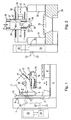
- Fig. 1 illustrated universal milling machine includes a rear stand 1 and arranged at the lower front of the machine bed 2, on which a workpiece table 4 in the direction of the Y-coordinate axis is movably moved in guide rails 3.
- a horizontal slide 7 is arranged to be movable by motor in the direction of the X-coordinate axis, on the front end side of a cross slide 9 is guided in vertical guide rails 10 in the direction of the Z-coordinate axis.
- a head 11 is rotatably mounted about the horizontal axis 12, on the front 45 ° -Sschräg components 13 a about the 45 ° -Schägachse 14 motorized movable swivel head 15 is mounted.
- a spindle housing 16 is attached, in the left part of a spindle motor 17 and before a work spindle 18 are arranged - each shown in phantom.
- a sensor 20 is arranged in the rear region of the spindle motor 17, which detects the current consumption of the motor 17 continuously.
- a vibration sensor 21 which detects the vibration occurring at the tool holder or the clamped tool during work.
- the two sensors 20 and 21 form a sensor, which are connected via data lines 22, 23 with an evaluation unit 24 which is connected to a conventional control unit 25.
- a data line 26 leads to a display 28, as a rotationally fixed circular lighting element in a side wall of the support head 11 in an ergonomic Favorable position is located so that it is located in the immediate field of view of a laterally standing next to the machine operator.
- This display element 28 includes a transparent housing capsule, in which a plurality of luminous bodies, such as LEDs, is arranged.
- the display element 28 is further subdivided into three fields, a larger green field occupying 60% of the luminous area, a medium yellow / orange field occupying 20% of the luminous area, and a smaller red field representing 20% of the luminous area occupies.
- a larger green field occupying 60% of the luminous area
- a medium yellow / orange field occupying 20% of the luminous area
- a smaller red field representing 20% of the luminous area occupies.
- more or fewer rows of LEDs become visible as a green, yellow / orange or red field.
- the green field indicates the normal operating state
- the yellow / orange field indicates a beginning critical operating state
- the red field indicates a dangerous operating state of the machine tool, in each case corresponding to the size of the recorded current consumption and / or vibration parameters.
- further operating parameters such as, for example, temperatures of particularly stressed components or the like, can be detected by corresponding sensors and included in the monitoring via the evaluation unit.
- Milling and drilling machine shown schematically in front view includes a substructure 30 with side walls 31, 32 fixed thereon and a workpiece table 33 arranged between these two side walls.
- a cross-beam 35 in the direction of the Y-axis.
- Coordinate axis mounted movable by motor, at the front side of a cross slide 36 and at the front end side of a vertical slide 37 are arranged respectively movably movable in guide rails.
- electrical Linear motors for example 37.
- the movable in the direction of the Z-coordinate axis vertical slide forms the support of a vertical milling head 38, in whose housing a work spindle and its drive motor are mounted.
- a sensor 21 is provided in the front region of the spindle housing 38, which is connected via the data line 22 to an evaluation unit 24 in this embodiment.
- a further sensor 20 is arranged, which detects the current consumption of the electric drive motor and is connected via the data line 23 to the evaluation unit 24. From this evaluation unit 24 performs a data line 26 to a display element 40, the display element 28 in accordance with its function Fig. 1 corresponds, but here has an oval elongated shape.
- this display element 40 includes a plurality of colored fields or areas that light up depending on the size of the continuously detected operating parameter in a specific color and thereby indicate to the operator the respective operating state of the machine tool.
- the display according to the invention expediently contains a scaling, for example in the form of a line scale for a percentage field size distribution.
- a scaling on the basis of an alternating number is preferred to activated lighting elements, ie LEDs, in adaptation to the size and / or significance of the measured operating parameter.
- a method for setting up the machine tool for machining a specific workpiece is characterized by the fact that the operator visually observes the tool / workpiece interface in the work area of the machine during the setup work - in simultaneous or actual operation.
- the operator may select keyboard operating parameters, e.g. Spindle feed, spindle speed and the like. adjust so that the constantly-monitored indicator is in the upper part of the field you are creating.
- sensors for detecting a plurality of different operating parameters can be provided and connected to the evaluation unit or also directly to the control unit. Depending on the priority of the respective operating parameter, the measured values of the individual sensors can be displayed separately in the display element via the evaluation unit. It is also possible for the evaluation unit to link the measured values of the various operating parameters with one another and to supply data from a combination of these measured values to the display unit.
- the bearing temperatures of the work spindle, the power consumption of the spindle motor and the vibrations of the tool holder can be measured individually and displayed individually - possibly in alternating sequence - as a parameter.
- the three or more parameters can also be processed in the evaluation unit to form a common data record which is displayed and indicates the operating state of the machine with combined evaluation of the parameters.
Landscapes
- Engineering & Computer Science (AREA)
- Mechanical Engineering (AREA)
- Numerical Control (AREA)
- Machine Tool Sensing Apparatuses (AREA)
Description
- Die Erfindung betrifft eine programmgesteuerte Fräs- und Bohrmaschine, mit einer in mehreren Koordinatenachsen motorisch verfahrbaren Bearbeitungseinheit, in der eine Arbeitsspindel zur auswechselbaren Aufnahme eines Spanwerkzeugs sowie ein E-Motor als Drehantrieb der Arbeitsspindel eingebaut sind, mit einer programmierbaren Steuereinheit und mit einer Einrichtung zur Überwachung von Betriebszuständen der Werkzeugmaschine.
- Aus der
US 2003/182014 A1 ist eine Einreichung zur gleichzeitigen Überwachung eines Betriebszustandes mehrerer Produktionsmaschinen bekannt. Jede dieser Maschinen in der Prozesslinie enthält mehrere spezielle Werkzeuge zum Schneiden, Bohren, Abdrehen oder Polieren eines Werkstücks. Um den Grad des Veschleißes der Spanwerkzeuge bestimmten zu können, werden die Spanoperationen jedes Werkzeugs erfasst und für jede überwachte Maschine in einem gesonderten Zähler gezählt. Ein Prozessor vergleicht die Zählerergebnisse mit vorgegebenen Werten, welche die Lebensdauer des jeweiligen Spanwerkzeugs kennzeichnen. Die Vergleichsergebnisse werden in einem Mehrfarben-Display angezeigt und ermöglichen durch geeignete Farbgebund dem Bediener eine Abschätzung des Verschleißzustandes des jeweils im Betrieb befindlichen Werkzeugs. Das Mehrfarben-Display ist integrierter Bestandteil der Anzeigeneinrichtung. - Daneben ist in der
US 5,152,327 eine für den Einsatz in Holzbearbeitungsmaschinen konzipierte Warnvorrichtung beschrieben, die bei einem sog. Nachlauf einer Arbeitsspindel bzw. eines Werkzeugs ein optisches Warnsignal abgibt. Die beschriebene und dargestellte Maschine enthält mehrere Bearbeitungseinheiten mit je einer motorgetriebenen Arbeitsspindel, die nebeneinander gemeinsam an einem horizontal in Y-Richtung verfahrbaren Schlitten montiert sind. Die Arbeitsspindeln in dieser Reihe von Bearbeitungseinheiten können einzeln in der vertikalen Z-Achse verfahren werden. Jede Bearbeitungseinheit besitzt als optische Anzeige eine Warnlampe, die an einer Stirnseite einer oberen Verlängerung der Haube des jeweiligen Spindelmotors montiert ist. Alle Warnlampen und Spindelmotoren sind an eine Programmsteuerung angeschlossen, welche einzelne dieser Warnlampen einschaltet, wenn in die jeweils zugeordnete Arbeitsspindel nach Abschalten ihres Spindelmotors durch Wirkung ihrer Masseträgheit weiterläuft. Nach einer einstellbaren Zeitspanne erfolgt das Abschalten der Warnlampe. Die Verwendung von mehrfarbigen Warnlampen, die durch unterschiedliche Farbgebung bestimmte Betriebszustände anzeigen könnten, ist bei dieser bekannten Warnvorrichtung weder vorgesehen noch technisch sinnvoll. - Bei modernen programmgesteuerten Werkzeugmaschinen und Bearbeitungszentren kommt dem Einrichten der Maschine vor der Bearbeitung eines bestimmten Werkstücks bzw. einer Werkstückserie eine erhebliche Bedeutung zur Erzielung von ungestörten Arbeitsabläufen unter optimierten Bedingungen zu. Daneben ist auch eine kontinuierliche Überwachung der Betriebszustände während des Arbeitsbetriebs der Maschine wesentlich, um mögliche Störfaktoren bereits in einem frühen Entwicklungsstadium zu erkennen und rechtzeitig Gegenmaßnahmen einleiten zu können. Das Einrichten der Maschine vor Beginn der Arbeiten und auch deren Zustandsüberwachung während des Betriebes erfolgt bisher ausschließlich über das Steuerpult der Steuereinheit, das sich in der Regel auf einem begrenzt bewegbaren Ständer neben oder schräg vor der Maschine befindet. Somit muss der Bediener beim Einfahren der Bearbeitung die Anzeigen der relevanten Betriebsparameter auf dem Steuerpult beobachten und möglichst gleichzeitig auch die tatsächliche Arbeitsweise des Werkzeuges - im simultanen o des Kühlschmierstoffs verwendet werden. Da die Auswerteeinheit einerseits mit der Sensorik und andererseits mit der Steuereinheit verbunden ist, können Daten aus der Steuereinheit und Messdaten aus der Sensorik miteinaner verknüpft und verarbeitet werden, um Daten für den jeweiligen Betriebszustand der Maschine zu erhalten. Eine intensive und ermüdungsarme Anzeige wird dadurch erzielt, dass das optische Anzeigeelement im direkten Sichtbereich des Bedieners an einem Maschinenteil angeordnet ist, wobei die Anzeige auf der Grundlage der von der Auswerteeinheit ausgegebenen Daten einen normalen, einen kritischen, und einen gefährlichen Betriebszustand der Maschine anzeigt.
- Die erfindungsgemäße Überwachungseinrichtung bietet u.a. den Vorteil, dass ein Bediener normale und auch kritische Betriebszustände einer Werkzeugmaschine frühzeitig und auf einfache Weise erkennen kann, und zwar durch die für ihn primäre Beobachtung der vorzugsweise im Arbeitsbereich der Maschine angeordneten optischen Anzeige. Ein Beobachtungswechsel zwischen dem Display auf dem Steuerpult und dem Arbeitsbereich des Werkzeugs ist nicht mehr erforderlich. Die Anzeige der jeweiligen Betriebszustände in unterschiedlichen Farben fördert die Langzeit-Aufmerksamkeit des Bedieners, insbesondere bei einem plötzlichen Farbwechsel. Damit besteht die Möglichkeit, dass Störungen und Fehler durch eine Farbänderung in der Anzeige frühzeitig und vor ihrem Wirksamwerden erkannt werden können, sodass vom Bediener oder auch von der Steuerung Gegenmaßnahmen eingeleietet werden können, bevor sich die Fehlfunktionen praktisch auswirken. Das Erfassen und die Anzeige im Vorfeld des Auftretens von Fehlern führen zu verbesserten Betriebsabläufen und zu verringerten Stillstandszeiten der Maschine. Diese Effekte wirken sich nicht nur bei der Zustandsüberwachung einer einzelnen Maschine aus, sondern ihre vorteilhafte Wirkung zeigt sich auch dann, wenn ein einzelner Bediener eine Gruppe von Maschinen bedienen und überwachen muss.
- Obwohl eine optische Anzeige in vorzugsweise drei Ampelfarben die Überwachungsfunktion in ausreichendem Maße erfüllt, kann es doch zweckmäßig sein, die optische Anzeige mit einer akustischen Anzeige zu kombinieren, um dadurch den Aufmerksamkeitsfaktor zu erhöhen.
- Gemäß einer zweckmäßigen Ausgestalung der Erfindung enthält die Anzeige mehrere Farbbereiche, die wechselweise aktiviert werden, und zwar Grün für Normalbetrieb, Gelb/Orange für kritischen Betrieb und Rot für gefährlichen Betrieb. Dabei sollte das grüne Feld für den Normalbetrieb wesentlich größer als das gelb/orange Feld für den kritischen Betrieb, und dieses wiederum größer als das rote Feld für den gefährlichen Betriebszustand in einem speziellen Anzeigeelement sein. Als besonders zweckmäßig hat sich eine prozentuale Feldgrößenverteilung von 60% Grün, 20% Gelb/Orange und 10% Rot erwiesen. Das große grüne Feld steht für einen normalen Betriebszustand, wobei die relative Größe des grünen Feldes die Ist-Größe des überwachten Betriebsparameters angibt. Beim Einrichten der Maschine kann daher der Bediener die Maschine auf einen Wert einrichten, der nahe der oberen Grenze des Grün-Feldes liegt, d.h. etwas unter 60%. Damit kann der Bediener beispielsweise den Vorschub des Werkzeugs so groß wählen, dass die Stromaufnahme des E-Motors der Arbeitsspindel sich im oberen Bereich des grünen Feldes befindet. Der auf diese Weise optimierte Vorschub führt zu entsprechenden Spanleistungen. Eine ähnliche Vorgehensweise kann beispielsweise durch die Überwachung von Vibrationen an der Werkzeugaufnahme erfolgen.
- Das gelb/orange Feld im optischen Anzeigeelement weist den Bediener darauf hin, dass beispielsweise die Stromaufnahme des Spindelmotors oder auch die Vibrationen der Arbeitsspindel oder des Werkzeugs sich im Grenzbereich befinden und in Kürze Maßnahmen eingeleitet werden sollten, um diese Betriebsparameter auf ihre Normalgröße zurückzuführen. Dies kann beispielsweise durch Verringerung des Vorschubs, durch einen Werkzeugwechsel oder auch durch andere Maßnahmen erfolgen. Wesentlich ist, dass der Aufwand und die Sorgfalt zur Überwachung einer Maschine bei der Durchführung unterschiedlichster Einrichtarbeiten sowei auch zur Überwachung einer Mehrzahl von Maschinen für einen Bediener herabgesetzt ist, was sich auf den Dauerbetrieb aller Maschinen vorteilhaft auswirkt.
- Zweckmäßig ist die Anzeige als optisches Leuchtelement außen an einer Seitenwand der Bearbeitungseinheit angeordnet, sodass sie sich im unmittelbaren Sichtbereich des Bedieners befindet, wenn dieser den Betrieb eines Werkzeuges an einem Werkstück im Arbeitsbereich der Maschine beobachtet.
- Vorzugsweise enthält die Anzeige eine Mehrzahl von Leuchtkörpern, wie LEDs, die in einer Gehäusekapsel mit transparenter Außenwand angeordnet und elektrisch mit der Auswerteeinheit bzw. mit der Steuereinheit verbunden sind. Dabei ist es vorteilhaft, wenn die Anzahl der jeweiligen Leuchtkörper der gemessenen Größe des jeweiligen Parameters proportional ist, sodass dem Bediener durch die Anzahl der jeweils aktivierten Leuchtkörper und damit durch die Größe des jeweiligen Leuchtfeldes auch die Größe und Wertigkeit des jeweils relevanten Betriebsparameters angezeigt werden.
- Im Folgenden werden Ausführungsbeispiele der Erfindung anhand der Zeichnung im Einzelnen beschrieben. Es zeigen:
- Fig. 1
- eine Universal-Fräsmaschine mit Schwenkkopf in schematischer Seitenansicht,
- Fig. 2
- eine Vertikal-Fräsmaschine mit vertikal ausgerichtetem Spindelkopf.
- Die in
Fig. 1 dargestellte Universal-Fräsmaschine enthält einen rückwärtigen Ständer 1 und ein an dessen unterer Vorderseite angeordnetes Maschinenbett 2, auf dem in Führungsschienen 3 ein Werkstücktisch 4 in Richtung der Y-Koordinatenachse motorisch verfahrbar ist. In horizontalen Führungsschienen 5, 6 an der Vorderseite des Ständers 1 ist ein Horizontalschlitten 7 in Richtung der X-Koordinatenachse motorisch verfahrbar angeordnet, an dessen vorderer Stirnseite ein Querschlitten 9 in vertikalen Führungsschienen 10 in Richtung der Z-Koordinatenachse motorisch verfahrbar geführt ist. An der Stirnseite des Querschlittens 9 ist ein Kopf 11 um die horizontale Achse 12 verdrehbar montiert, an dessen vorderer 45°-Schrägfläche 13 ein um die 45°-Schrägachse 14 motorisch bewegbarer Schwenkkopf 15 gelagert ist. An einer Katheterfläche dieses Schwenkkopfes 15 ist ein Spindelgehäuse 16 befestigt, in dessen linkem Teil ein Spindelmotor 17 und davor eine Arbeitsspindel 18 angeordnet sind - jeweils gestrichelt dargestellt. Am rückwärtigen Ende des Spindelgehäuses 16 ist im hinteren Bereich des Spindelmotors 17 ein Sensor 20 angeordnet, der die Stromaufnahme des Motors 17 kontinuierlich erfasst. Am vorderen Endbereich des Spindelgehäuses 16 befindet sich ein Vibrationssensor 21, der die an der Werkzeugaufnahme bzw. dem eingespannten Werkzeug während der Arbeit auftretenden Vibrationen erfasst. Die beiden Sensoren 20 und 21 bilden eine Sensorik, die über Datenleitungen 22, 23 mit einer Auswerteeinheit 24 verbunden sind, die an eine herkömmliche Steuereinheit 25 angeschlossen ist. Von der Steuereinheit 25 führt eine Datenleitung 26 zu einer Anzeige 28, die als drehfestes kreisrundes Leuchtelement in einer Seitenwand des Tragkopfes 11 in einer ergonomisch günstigenPosition angeordnet ist, sodass sie sich im unmittelbaren Sichtbereich eines seitlich neben der Maschine stehenden Bedieners befindet. Dieses Anzeigeelement 28 enthält eine transparente Gehäusekapsel, in der eine Mehrzahl von Leuchtkörpern, wie LEDs, angeordnet ist. Das Anzeigeelement 28 ist ferner in drei Felder unterteilt, und zwar in ein größeres grünfarbiges Feld, das 60 % der Leuchtfläche einnimmt, ein mittelgroßes gelb/oranges Feld, das 20 % der Leuchtfläche einnimmt, und ein kleineres rotes Feld, das 20 % der Leuchtfläche einnimmt. Je nach den von der Sensorik 20, 21 ermittelten Messwerten und dem in der Auswerteeinheit 24 festgestellten Betriebszustand werden mehr oder weniger Reihen von LEDs als grünes, gelbes/oranges oder als rotes Feld sichtbar. Das grüne Feld kennzeichnet den normalen Betriebszustand, das gelb/orange Feld einen beginnenden kritischen Betriebszustand und das rote Feld einen gefährlichen Betriebszustand der Werkzeugmaschine, jeweils entsprechend der Größe der erfassten Stromaufnahme- und/oder Vibrationsparameter. Zur Überwachung weiterer Zustände und Eigenschaften der Werkzeugmaschine können auch weitere Betriebsparameter, wie beispielsweise Temperaturen besonders beanspruchter Bauteile od. dgl., durch entsprechende Sensoren erfasst und über die Auswerteeinheit in die Überwachung einbezogen werden. - Die in
Fig. 2 in Vorderansicht schematisch dargestellte Fräs- und Bohrmaschine enthält einen Unterbau 30 mit darauf befestigten Seitenwänden 31, 32 und einem zwischen diesen beiden Seitenwänden angeordneten Werkstücktisch 33. In zwei auf der Oberseite der Seitenwände 31, 32 montierten Führungsschienen ist eine Quertraverse 35 in Richtung der Y-Koordinatenachse motorisch verfahrbar montiert, an deren Vorderseite ein Querschlitten 36 und an dessen vorderer Stirnseite ein Vertikalschlitten 37 jeweils in Führungsschienen motorisch verfahrbar angeordnet sind. Zum Antrieb der Schlitten dienen hier elektrische Linearmotoren z.B. 37. Der in Richtung der Z-Koordinatenachse verfahrbare Vertikalschlitten bildet den Träger eines vertikalen Fräskopfes 38, in dessen Gehäuse eine Arbeitsspindel und deren Antriebsmotor gelagert sind. - Zum Erfassen der im spanenden Betrieb auftretenden Schwingungen an der Werkzeugaufnahme 39 bzw. dem darin eingespannten Werkzeug ist auch bei dieser Ausführung ein Sensor 21 im vorderen Bereich des Spindelgehäuses 38 vorgesehen, der über die Datenleitung 22 mit einer Auswerteeinheit 24 verbunden ist. In gleicher Weise wie bei der Ausführung nach
Fig. 1 ist im Endbereich des Spindel-Antriebsmotors im Spindelgehäuse 38 ein weiterer Sensor 20 angeordnet, der die Stromaufnahme des elektrischen Antriebsmotors erfasst und über die Datenleitung 23 mit der Auswerteeinheit 24 verbunden ist. Von dieser Auswerteeinheit 24 führt eine Datenleitung 26 zu einem Anzeigenelement 40, das hinsichtlich seiner Funktion dem Anzeigenelement 28 gemäßFig. 1 entspricht, hier jedoch eine oval langgestreckte Form hat. Auch dieses Anzeigenelement 40 enthält mehrere farbige Felder bzw. Bereiche, die je nach der Größe des kontinuierlich erfassten Betriebsparameters in einer spezifischen Farbe aufleuchten und dadurch dem Bediener den jeweiligen Betriebszustand der Werkzeugmaschine anzeigen. Dabei kann die Anzeige nur eines einzigen Parameters, beispielsweise der gemessenen Vibrationen oder der Stromaufnahme des Spindelmotors, erfolgen, und zwar je nach Einstellung durch den Bediener über Tasten oder Schalter, die entweder in dem Steuerpult der Steuereinheit oder aber in oder an der Auswerteeinheit vorgesehen sein können. - Die erfindungsgemäße Anzeige enthält zweckmäßig eine Skalierung z.B. in Form einer Strichskala für eine prozentuale Feldgrößenverteilung. Bevorzugt wird eine Skalierung auf der Basis einer wechselnden Anzahl an aktivierten Leuchtelementen, d.h. LEDs, in Anpassung an die Größe und/oder Wertigkeit des gemessenen Betriebsparameters.
- Ein Verfahren zum Einrichten der Werkzeugmaschine für die Bearbeitung eines bestimmten Werkstücks zeichnet sich dadurch aus, dass der Bediener während der Vornahme der Einrichtarbeiten - im simultanen oder im tatsächlichen Betrieb - die Schnittstelle Werkzeug/Werkstück im Arbeitsbereich der Maschine visuell beobachtet. Zur Optimierung der Arbeitsabläufe und -ergebnisse kann der Bediener Betriebsparameter auf der Tastatur, z.B. Spindelvorschub, Spindeldrehzahl u.dgl. so einstellen, dass sich die ständig beobachtete Anzeige im oberen Bereich des gründen Feldes befindet.
- Die Erfindung ist nicht auf die dargestellten und vorstehend beschriebenen Ausführungsbeispiele beschränkt. So können Sensoren zum Erfassen einer Vielzahl unterschiedlicher Betriebsparameter vorgesehen und mit der Auswerteeinheit bzw. auch direkt mit der Steuereinheit verbunden sein. Die Messwerte der einzelnen Sensoren können je nach Priorität des jeweiligen Betriebsparameters über die Auswerteeinheit gesondert in dem Anzeigeelement angezeigt werden. Es besteht auch die Möglichkeit, dass die Auswerteeinheit die Messwerte der verschiedenen Betriebsparameter miteinander verknüpft und Daten aus einer Kombination dieser Messwerte der Anzeigeeinheit zuführt. So können beispielsweise die Lagertemperaturen der Arbeitsspindel, die Stromaufnahme des Spindelmotors und die Vibrationen der Werkzeugaufnahme einzeln gemessen und einzeln - ggf. in wechselnder Folge - als Parameter angezeigt werden. Die drei - oder mehr - Parameter können in der Auswerteeinheit auch zu einem gemeinsamen Datensatz verarbeitet werden, der angezeigt wird und den Betriebszustand der Maschine bei kombinierter Wertung der Parameter angibt.
Claims (6)
- Programmgesteuerte Fräs- und Bohrmaschine, mit- einer in mehreren Koordinatenachsen motorisch verfahrbaren Bearbeitungseinheit, in der eine Arbeitsspindel (18) zur auswechselbaren Aufnahme eines Spanwerkzeugs sowie ein E-Motor (17) als Antrieb der Arbeitsspindel (18) eingebaut sind,- einer programmierbaren Steuereinheit (25) und- einer Einrichtung zur Überwachung des Betriebszustands der Werkzeugmaschine, die aufweistdadurch gekennzeichnet, dass- mindestens eine Sensorik (20, 21) zum Erfassen mindestens eines Betriebsparameters an einem für diesen Parameter relevanten Bauteil (11, 38) der Werkzeugmaschine,- eine mit der Sensorik (20, 21) und auch mit der Steuereinheit (25) verbundene Auswerteeinheit (24), welche die von der Sensorik (20, 21) erfassten Messwerte verarbeitet, und- eine optische Anzeige (28, 40), die entsprechend den Daten aus der Auswerteeinheit (24) einen normalen, einen kritischen und einen gefährlichen Betriebszustand der Werkzeugmaschine anzeigt, wobei- die optische Anzeige ein Anzeigeelement (28, 40) enthält,- das Anzeigeelement (28, 40) je nach Betriebszustand wechselnde Farbbereiche enthält, grün für normalen Betriebszustand, gelb/orange für kritischen Betriebszustand, und rot für gefährlichen Betriebszustand- das Anzeigeelement (28, 40) in ergonomisch günstiger Position im direkten Sichtbereich des Bedieners außen an einer Seitenwand der Bearbeitungseinheit angeordnet ist,- das Anzeigeelement (28, 40) eine Mehrzahl von Leuchtkörpern enthält, die in einer transparenten Gehäusekapsel angeordnet und elektrisch mit der Auswerteeinheit (24) bzw. mit der Steuereinheit (25) verbunden sind, und- wobei von der gesamten Farbfläche des Anzeigeelements (28, 40) der grüne Bereich etwa 60 bis 70 %, der gelb/orange Bereich 20 bis 30 % und der rote Bereich 10 bis 20 % einnimmt, und- wobei die relative Größe des jeweils aktiven Farbbereichs die Ist-Größe des überwachten Betriebsparameters angibt.
- Werkzeugmaschine nach Anspruch 1,
dadurch gekennzeichnet, dass
die Auswerteeinheit (24) mit der Steuereinheit (25) funktional verknüpft ist und aus den Messdaten der Sensorik (20, 21) sowie aus Daten der Steuereinheit (25) die jeweilige Zustandsgröße des überwachten Betriebsparameters bestimmt und die der Zustandsgröße entsprechende Farbe im Anzeigeelement (28, 40) aktiviert. - Werkzeugmaschine nach einem der vorstehenden Ansprüche,
dadurch gekennzeichnet, dass
das Anzeigeelement (28, 40) eine Skalierung enthält, die den Größenanteil des jeweils farbig aktiven Bereichs angibt. - Werkzeugmaschine nach einem der vorstehenden Ansprüche,
dadurch gekennzeichnet, dass
das Anzeigeelement (28) als drehfestes, kreisrundes Leuchtelement ausgebildet ist. - Werzeugmaschine nach einem der vorstehenden Ansprüche,
dadurch gekennzeichnet, dass
die Sensorik (20, 21) einen Vibrationssensor (21) enthält, der die an der Werkzeugaufnahme im Arbeitsbetrieb auftretenden Vibrationen erfasst und der über eine Datenleitung (23) mit der Auswerteeinheit (24) verbunden ist. - Werkzeugmaschine nach einem der vorstehenden Ansprüche,
dadurch gekennzeichnet, dass
die Sensorik (20, 21) einen im hinteren Bereich des Spindelmotors (17) angeordneten Sensor (20) enthält, der die Stromaufnahme des Spindelmotors kontinuierlich erfasst und der über eine Datenleitung (22) mit der Auswerteeinheit (24) verbunden ist.
Applications Claiming Priority (1)
| Application Number | Priority Date | Filing Date | Title |
|---|---|---|---|
| DE102010054855.3A DE102010054855B4 (de) | 2010-12-17 | 2010-12-17 | Werkzeugmaschine, insbesondere programmgesteuerte Fräs- und Bohrmaschine |
Publications (4)
| Publication Number | Publication Date |
|---|---|
| EP2465639A2 EP2465639A2 (de) | 2012-06-20 |
| EP2465639A3 EP2465639A3 (de) | 2013-06-12 |
| EP2465639B1 true EP2465639B1 (de) | 2016-03-02 |
| EP2465639B9 EP2465639B9 (de) | 2016-09-07 |
Family
ID=45349392
Family Applications (1)
| Application Number | Title | Priority Date | Filing Date |
|---|---|---|---|
| EP11193719.9A Not-in-force EP2465639B9 (de) | 2010-12-17 | 2011-12-15 | Werkzeugmaschine |
Country Status (6)
| Country | Link |
|---|---|
| US (1) | US20120158170A1 (de) |
| EP (1) | EP2465639B9 (de) |
| JP (1) | JP5823848B2 (de) |
| CN (1) | CN102554699B (de) |
| DE (1) | DE102010054855B4 (de) |
| ES (1) | ES2571102T3 (de) |
Families Citing this family (10)
| Publication number | Priority date | Publication date | Assignee | Title |
|---|---|---|---|---|
| JP5938468B2 (ja) * | 2012-04-16 | 2016-06-22 | 株式会社牧野フライス製作所 | 工作機械 |
| CN103317102A (zh) * | 2013-06-27 | 2013-09-25 | 常州午阳柴油机水箱制造有限公司 | 一种射芯机制芯工艺及其装置 |
| US10295475B2 (en) | 2014-09-05 | 2019-05-21 | Rolls-Royce Corporation | Inspection of machined holes |
| US9682455B2 (en) * | 2014-10-28 | 2017-06-20 | Dmg Mori Seiki Co., Ltd. | Chatter application interface |
| US10228669B2 (en) | 2015-05-27 | 2019-03-12 | Rolls-Royce Corporation | Machine tool monitoring |
| TWI850251B (zh) | 2018-09-03 | 2024-08-01 | 義大利商Hsd股份公司 | 工具機、用於工具機的操作裝置、以及收集工具機的操作資料的系統及方法 |
| CN109759852A (zh) * | 2018-12-25 | 2019-05-17 | 大族激光科技产业集团股份有限公司 | 一种操作面板的安装固定装置 |
| EP3825062A1 (de) * | 2019-11-21 | 2021-05-26 | Hilti Aktiengesellschaft | Verfahren zum betreiben einer werkzeugmaschine und werkzeugmaschine |
| JP7706266B2 (ja) * | 2021-06-07 | 2025-07-11 | コマツNtc株式会社 | 回転割出し装置を含む工作機械 |
| DE102023105146A1 (de) | 2023-03-02 | 2024-09-05 | Gebr. Heller Maschinenfabrik Gmbh | Werkzeugmaschine mit Einfahr-Assistent |
Citations (1)
| Publication number | Priority date | Publication date | Assignee | Title |
|---|---|---|---|---|
| DE10228389A1 (de) * | 2002-04-13 | 2003-10-30 | I For T Gmbh | Schwingungssensor und Verfahren zur Zustandsüberwachung von rotierenden Bauteilen und Lagern |
Family Cites Families (22)
| Publication number | Priority date | Publication date | Assignee | Title |
|---|---|---|---|---|
| US4442493A (en) * | 1980-07-04 | 1984-04-10 | Kabushiki Kaisha Komatsu Seisakusho | Cutting tool retreat and return for workpiece protection upon abnormality occurrence in a preprogrammed machine tool |
| DE9010313U1 (de) * | 1990-07-07 | 1992-01-02 | C. & E. Fein Gmbh & Co, 7000 Stuttgart | Bohreinrichtung |
| JPH04123107A (ja) * | 1990-09-13 | 1992-04-23 | Fanuc Ltd | 負荷状態描画方式 |
| US5070655A (en) * | 1990-11-30 | 1991-12-10 | Aggarwal Trilok R | Machining process monitor |
| JPH0592341A (ja) * | 1991-09-27 | 1993-04-16 | Isao Shoda | スピンドルの回転警告装置 |
| US9513744B2 (en) * | 1994-08-15 | 2016-12-06 | Apple Inc. | Control systems employing novel physical controls and touch screens |
| JPH09244728A (ja) * | 1996-03-13 | 1997-09-19 | Fanuc Ltd | オンライン端末として利用されるcnc装置のデータ表示・入力方法 |
| EP0913229B1 (de) * | 1997-03-15 | 2005-01-19 | Makino Milling Machine Co. Ltd. | Prozessor für maschinelle bearbeitung |
| US6033288A (en) * | 1998-10-29 | 2000-03-07 | Kulicke & Soffa Investments, Inc. | Monitoring system for dicing saws |
| US7010386B2 (en) * | 2002-03-22 | 2006-03-07 | Mcdonnell Ryan P | Tool wear monitoring system |
| US7117050B2 (en) * | 2002-11-08 | 2006-10-03 | Toshiba Kikai Kabushiki Kaisha | Management supporting apparatus, management supporting system, management supporting method, management supporting program, and a recording medium with the program recorded therein |
| DE102005025673A1 (de) * | 2005-06-03 | 2006-12-14 | Siemens Ag | Betriebsverfahren für eine Auswertungseinrichtung für eine Produktionsmaschine |
| DE102007041097A1 (de) * | 2006-09-04 | 2008-03-06 | Robert Bosch Gmbh | Werkzeugmaschinenüberwachungsvorrichtung |
| US8068104B2 (en) * | 2007-06-29 | 2011-11-29 | Carlyle Rampersad | Totally integrated intelligent dynamic systems display |
| US7609152B2 (en) * | 2007-08-24 | 2009-10-27 | Paccar Inc | Error handling for multi-functional display |
| JP4898632B2 (ja) * | 2007-11-08 | 2012-03-21 | 本田技研工業株式会社 | 車両用表示装置 |
| WO2009090597A1 (en) * | 2008-01-16 | 2009-07-23 | Koninklijke Philips Electronics N.V. | User interface for scene setting control with light balance |
| US20090192728A1 (en) * | 2008-01-30 | 2009-07-30 | Honeywell International Inc. | Apparatus, system, and method for onboard degraded and deadlined mechanical system alerting |
| DE102008029672B3 (de) * | 2008-06-24 | 2010-02-25 | I-For-T Gmbh | Vorrichtung und Verfahren zur Zustandsüberwachung und Zustandsdiagnose einer Maschine, Maschinenkomponente oder Anlage |
| CN101571712A (zh) * | 2008-11-26 | 2009-11-04 | 天津大学 | 一种具有加工自适应功能与在机质量检测的监控方法 |
| DE202009009390U1 (de) * | 2009-07-09 | 2009-11-12 | Nc-Automation Gmbh | Tasteinheit für CNC-Maschinen |
| US8723869B2 (en) * | 2011-03-21 | 2014-05-13 | Tokyo Electron Limited | Biologically based chamber matching |
-
2010
- 2010-12-17 DE DE102010054855.3A patent/DE102010054855B4/de not_active Expired - Fee Related
-
2011
- 2011-12-15 EP EP11193719.9A patent/EP2465639B9/de not_active Not-in-force
- 2011-12-15 ES ES11193719T patent/ES2571102T3/es active Active
- 2011-12-16 CN CN201110422863.4A patent/CN102554699B/zh not_active Expired - Fee Related
- 2011-12-16 JP JP2011275911A patent/JP5823848B2/ja not_active Expired - Fee Related
- 2011-12-16 US US13/328,575 patent/US20120158170A1/en not_active Abandoned
Patent Citations (1)
| Publication number | Priority date | Publication date | Assignee | Title |
|---|---|---|---|---|
| DE10228389A1 (de) * | 2002-04-13 | 2003-10-30 | I For T Gmbh | Schwingungssensor und Verfahren zur Zustandsüberwachung von rotierenden Bauteilen und Lagern |
Also Published As
| Publication number | Publication date |
|---|---|
| CN102554699A (zh) | 2012-07-11 |
| EP2465639B9 (de) | 2016-09-07 |
| JP2012133781A (ja) | 2012-07-12 |
| US20120158170A1 (en) | 2012-06-21 |
| EP2465639A3 (de) | 2013-06-12 |
| DE102010054855A1 (de) | 2012-06-21 |
| EP2465639A2 (de) | 2012-06-20 |
| DE102010054855B4 (de) | 2015-06-11 |
| CN102554699B (zh) | 2016-08-24 |
| ES2571102T3 (es) | 2016-05-24 |
| JP5823848B2 (ja) | 2015-11-25 |
Similar Documents
| Publication | Publication Date | Title |
|---|---|---|
| EP2465639B9 (de) | Werkzeugmaschine | |
| EP1932618B2 (de) | Arbeitsmaschine | |
| DE602006000535T2 (de) | Numerisch gesteuerte Arbeitsanlage zum Bearbeitung Platten aus Glas, Stein, Marmor und dergleichen, mit zwei oder mehr Bearbeitungseinheiten | |
| EP0985493B1 (de) | Werkzeugmaschine mit automatischer Prozesssteuerung/Überwachung | |
| DE60116992T2 (de) | Werkzeugmaschine mit mindestens zwei Bearbeitungseinheiten | |
| DE202007014117U1 (de) | Fräs- und Bohrmaschine mit Palettenwechsler | |
| EP0705156B1 (de) | Verfahren zur vermeidung von überbeanspruchungen eines werkstückes beim schleifen | |
| DE1627089A1 (de) | Verfahren und Einrichtung zum genauen Einstellen des Abstandes zwischen einem Werkzeug und einem Werkstueck bei einer Werkzeugmaschine | |
| DE3009393A1 (de) | Steuerungseinrichtung zur erhoehung der arbeitsgenauigkeit einer werkzeugmaschine - insbesondere einer gross dimensionierten werkzeugmaschine | |
| DE102007037498B4 (de) | Werkzeugmaschine mit einer Werkzeugprüfvorrichtung | |
| DE4029113C2 (de) | Elektrische Entladungsbearbeitungsmaschine | |
| EP3168701A1 (de) | Verfahren zur darstellung der bearbeitung in einer werkzeugmaschine | |
| EP2310167B1 (de) | Verfahren zur ansteuerung des werkstückmanipulators einer werkzeugmaschine nach einer bearbeitungsabbruch | |
| US10222781B2 (en) | Apparatus for monitoring and providing visual representations of the operating conditions of machine tool parameters | |
| DE102010024655A1 (de) | Universal-Bearbeitungskopf für Werkzeugmaschinen | |
| DE102020205088A1 (de) | Verfahren und Auswertesystem zur Überwachung eines Werkzeugverschleißes von Werkzeugkomponenten bei zerspanenden Fertigungsanlagen | |
| DE102020209644B4 (de) | Verbesserte werkzeughaltervorrichtung, dazugehöriges erfassungssystem und bearbeitungsmaschine für holzteile, umfassend die vorrichtung und das system | |
| DE102023105146A1 (de) | Werkzeugmaschine mit Einfahr-Assistent | |
| DE3300734A1 (de) | Vorschubantrieb fuer eine mehrspindelmaschine | |
| CN213592395U (zh) | 一种带有防护装置的数控立式铣台 | |
| EP2372477B1 (de) | Holzbearbeitungsmaschine und Verfahren zur Vermeidung von Kollisionen von Maschinen- und/oder Werkzeugteilen an einer solchen Holzbearbeitungsmaschine | |
| DE102007023009A1 (de) | Kleinwerkzeugmaschinen-Sortiment | |
| EP0469414A2 (de) | Verfahren zum Vermessen eines Werkzeuges in einer numerisch gesteuerten Bearbeitungsmaschine mit automatischem Werkzeugwechsel und Einrichtung zur Durchführung dieses Verfahrens | |
| CH722183A2 (de) | Laserreinigungsmaschine mit handgeführtem Bearbeitungsmanipulator | |
| DE1752194C (de) | Einrichtung zur stufenlosen Verstellung des Spindelsturzes an Fräsmaschinen od. dgl |
Legal Events
| Date | Code | Title | Description |
|---|---|---|---|
| PUAI | Public reference made under article 153(3) epc to a published international application that has entered the european phase |
Free format text: ORIGINAL CODE: 0009012 |
|
| AK | Designated contracting states |
Kind code of ref document: A2 Designated state(s): AL AT BE BG CH CY CZ DE DK EE ES FI FR GB GR HR HU IE IS IT LI LT LU LV MC MK MT NL NO PL PT RO RS SE SI SK SM TR |
|
| AX | Request for extension of the european patent |
Extension state: BA ME |
|
| RIN1 | Information on inventor provided before grant (corrected) |
Inventor name: SEITZ, REINHOLD Inventor name: GRONBACH, HANS Inventor name: BORNEMANN, ARMIN Inventor name: PRUSCHEK, PETER |
|
| PUAL | Search report despatched |
Free format text: ORIGINAL CODE: 0009013 |
|
| AK | Designated contracting states |
Kind code of ref document: A3 Designated state(s): AL AT BE BG CH CY CZ DE DK EE ES FI FR GB GR HR HU IE IS IT LI LT LU LV MC MK MT NL NO PL PT RO RS SE SI SK SM TR |
|
| AX | Request for extension of the european patent |
Extension state: BA ME |
|
| RIC1 | Information provided on ipc code assigned before grant |
Ipc: G05B 19/4063 20060101ALI20130507BHEP Ipc: B23Q 17/00 20060101ALI20130507BHEP Ipc: B23Q 17/09 20060101AFI20130507BHEP |
|
| 17P | Request for examination filed |
Effective date: 20131212 |
|
| RBV | Designated contracting states (corrected) |
Designated state(s): AL AT BE BG CH CY CZ DE DK EE ES FI FR GB GR HR HU IE IS IT LI LT LU LV MC MK MT NL NO PL PT RO RS SE SI SK SM TR |
|
| 17Q | First examination report despatched |
Effective date: 20140212 |
|
| GRAJ | Information related to disapproval of communication of intention to grant by the applicant or resumption of examination proceedings by the epo deleted |
Free format text: ORIGINAL CODE: EPIDOSDIGR1 |
|
| GRAP | Despatch of communication of intention to grant a patent |
Free format text: ORIGINAL CODE: EPIDOSNIGR1 |
|
| GRAP | Despatch of communication of intention to grant a patent |
Free format text: ORIGINAL CODE: EPIDOSNIGR1 |
|
| INTG | Intention to grant announced |
Effective date: 20150924 |
|
| INTC | Intention to grant announced (deleted) | ||
| INTG | Intention to grant announced |
Effective date: 20151005 |
|
| GRAS | Grant fee paid |
Free format text: ORIGINAL CODE: EPIDOSNIGR3 |
|
| GRAA | (expected) grant |
Free format text: ORIGINAL CODE: 0009210 |
|
| AK | Designated contracting states |
Kind code of ref document: B1 Designated state(s): AL AT BE BG CH CY CZ DE DK EE ES FI FR GB GR HR HU IE IS IT LI LT LU LV MC MK MT NL NO PL PT RO RS SE SI SK SM TR |
|
| REG | Reference to a national code |
Ref country code: GB Ref legal event code: FG4D Free format text: NOT ENGLISH |
|
| REG | Reference to a national code |
Ref country code: AT Ref legal event code: REF Ref document number: 777666 Country of ref document: AT Kind code of ref document: T Effective date: 20160315 Ref country code: CH Ref legal event code: NV Representative=s name: MICHELI AND CIE SA, CH Ref country code: CH Ref legal event code: EP |
|
| REG | Reference to a national code |
Ref country code: IE Ref legal event code: FG4D Free format text: LANGUAGE OF EP DOCUMENT: GERMAN |
|
| REG | Reference to a national code |
Ref country code: DE Ref legal event code: R096 Ref document number: 502011008976 Country of ref document: DE |
|
| REG | Reference to a national code |
Ref country code: ES Ref legal event code: FG2A Ref document number: 2571102 Country of ref document: ES Kind code of ref document: T3 Effective date: 20160524 |
|
| REG | Reference to a national code |
Ref country code: NL Ref legal event code: MP Effective date: 20160302 |
|
| REG | Reference to a national code |
Ref country code: LT Ref legal event code: MG4D |
|
| PG25 | Lapsed in a contracting state [announced via postgrant information from national office to epo] |
Ref country code: NO Free format text: LAPSE BECAUSE OF FAILURE TO SUBMIT A TRANSLATION OF THE DESCRIPTION OR TO PAY THE FEE WITHIN THE PRESCRIBED TIME-LIMIT Effective date: 20160602 Ref country code: FI Free format text: LAPSE BECAUSE OF FAILURE TO SUBMIT A TRANSLATION OF THE DESCRIPTION OR TO PAY THE FEE WITHIN THE PRESCRIBED TIME-LIMIT Effective date: 20160302 Ref country code: HR Free format text: LAPSE BECAUSE OF FAILURE TO SUBMIT A TRANSLATION OF THE DESCRIPTION OR TO PAY THE FEE WITHIN THE PRESCRIBED TIME-LIMIT Effective date: 20160302 Ref country code: GR Free format text: LAPSE BECAUSE OF FAILURE TO SUBMIT A TRANSLATION OF THE DESCRIPTION OR TO PAY THE FEE WITHIN THE PRESCRIBED TIME-LIMIT Effective date: 20160603 |
|
| PG25 | Lapsed in a contracting state [announced via postgrant information from national office to epo] |
Ref country code: LT Free format text: LAPSE BECAUSE OF FAILURE TO SUBMIT A TRANSLATION OF THE DESCRIPTION OR TO PAY THE FEE WITHIN THE PRESCRIBED TIME-LIMIT Effective date: 20160302 Ref country code: SE Free format text: LAPSE BECAUSE OF FAILURE TO SUBMIT A TRANSLATION OF THE DESCRIPTION OR TO PAY THE FEE WITHIN THE PRESCRIBED TIME-LIMIT Effective date: 20160302 Ref country code: PL Free format text: LAPSE BECAUSE OF FAILURE TO SUBMIT A TRANSLATION OF THE DESCRIPTION OR TO PAY THE FEE WITHIN THE PRESCRIBED TIME-LIMIT Effective date: 20160302 Ref country code: LV Free format text: LAPSE BECAUSE OF FAILURE TO SUBMIT A TRANSLATION OF THE DESCRIPTION OR TO PAY THE FEE WITHIN THE PRESCRIBED TIME-LIMIT Effective date: 20160302 Ref country code: RS Free format text: LAPSE BECAUSE OF FAILURE TO SUBMIT A TRANSLATION OF THE DESCRIPTION OR TO PAY THE FEE WITHIN THE PRESCRIBED TIME-LIMIT Effective date: 20160302 Ref country code: NL Free format text: LAPSE BECAUSE OF FAILURE TO SUBMIT A TRANSLATION OF THE DESCRIPTION OR TO PAY THE FEE WITHIN THE PRESCRIBED TIME-LIMIT Effective date: 20160302 |
|
| PG25 | Lapsed in a contracting state [announced via postgrant information from national office to epo] |
Ref country code: EE Free format text: LAPSE BECAUSE OF FAILURE TO SUBMIT A TRANSLATION OF THE DESCRIPTION OR TO PAY THE FEE WITHIN THE PRESCRIBED TIME-LIMIT Effective date: 20160302 Ref country code: IS Free format text: LAPSE BECAUSE OF FAILURE TO SUBMIT A TRANSLATION OF THE DESCRIPTION OR TO PAY THE FEE WITHIN THE PRESCRIBED TIME-LIMIT Effective date: 20160702 |
|
| PG25 | Lapsed in a contracting state [announced via postgrant information from national office to epo] |
Ref country code: PT Free format text: LAPSE BECAUSE OF FAILURE TO SUBMIT A TRANSLATION OF THE DESCRIPTION OR TO PAY THE FEE WITHIN THE PRESCRIBED TIME-LIMIT Effective date: 20160704 Ref country code: SM Free format text: LAPSE BECAUSE OF FAILURE TO SUBMIT A TRANSLATION OF THE DESCRIPTION OR TO PAY THE FEE WITHIN THE PRESCRIBED TIME-LIMIT Effective date: 20160302 Ref country code: SK Free format text: LAPSE BECAUSE OF FAILURE TO SUBMIT A TRANSLATION OF THE DESCRIPTION OR TO PAY THE FEE WITHIN THE PRESCRIBED TIME-LIMIT Effective date: 20160302 Ref country code: RO Free format text: LAPSE BECAUSE OF FAILURE TO SUBMIT A TRANSLATION OF THE DESCRIPTION OR TO PAY THE FEE WITHIN THE PRESCRIBED TIME-LIMIT Effective date: 20160302 Ref country code: CZ Free format text: LAPSE BECAUSE OF FAILURE TO SUBMIT A TRANSLATION OF THE DESCRIPTION OR TO PAY THE FEE WITHIN THE PRESCRIBED TIME-LIMIT Effective date: 20160302 |
|
| REG | Reference to a national code |
Ref country code: DE Ref legal event code: R097 Ref document number: 502011008976 Country of ref document: DE |
|
| REG | Reference to a national code |
Ref country code: FR Ref legal event code: PLFP Year of fee payment: 6 |
|
| PLBE | No opposition filed within time limit |
Free format text: ORIGINAL CODE: 0009261 |
|
| STAA | Information on the status of an ep patent application or granted ep patent |
Free format text: STATUS: NO OPPOSITION FILED WITHIN TIME LIMIT |
|
| PG25 | Lapsed in a contracting state [announced via postgrant information from national office to epo] |
Ref country code: DK Free format text: LAPSE BECAUSE OF FAILURE TO SUBMIT A TRANSLATION OF THE DESCRIPTION OR TO PAY THE FEE WITHIN THE PRESCRIBED TIME-LIMIT Effective date: 20160302 |
|
| PGFP | Annual fee paid to national office [announced via postgrant information from national office to epo] |
Ref country code: GB Payment date: 20161228 Year of fee payment: 6 Ref country code: CH Payment date: 20161223 Year of fee payment: 6 |
|
| 26N | No opposition filed |
Effective date: 20161205 |
|
| PG25 | Lapsed in a contracting state [announced via postgrant information from national office to epo] |
Ref country code: SI Free format text: LAPSE BECAUSE OF FAILURE TO SUBMIT A TRANSLATION OF THE DESCRIPTION OR TO PAY THE FEE WITHIN THE PRESCRIBED TIME-LIMIT Effective date: 20160302 Ref country code: BG Free format text: LAPSE BECAUSE OF FAILURE TO SUBMIT A TRANSLATION OF THE DESCRIPTION OR TO PAY THE FEE WITHIN THE PRESCRIBED TIME-LIMIT Effective date: 20160602 |
|
| PGFP | Annual fee paid to national office [announced via postgrant information from national office to epo] |
Ref country code: FR Payment date: 20161229 Year of fee payment: 6 |
|
| PGFP | Annual fee paid to national office [announced via postgrant information from national office to epo] |
Ref country code: DE Payment date: 20161231 Year of fee payment: 6 |
|
| PG25 | Lapsed in a contracting state [announced via postgrant information from national office to epo] |
Ref country code: BE Free format text: LAPSE BECAUSE OF NON-PAYMENT OF DUE FEES Effective date: 20161231 |
|
| PGFP | Annual fee paid to national office [announced via postgrant information from national office to epo] |
Ref country code: ES Payment date: 20170127 Year of fee payment: 6 Ref country code: IT Payment date: 20161223 Year of fee payment: 6 |
|
| PG25 | Lapsed in a contracting state [announced via postgrant information from national office to epo] |
Ref country code: MC Free format text: LAPSE BECAUSE OF FAILURE TO SUBMIT A TRANSLATION OF THE DESCRIPTION OR TO PAY THE FEE WITHIN THE PRESCRIBED TIME-LIMIT Effective date: 20160302 |
|
| REG | Reference to a national code |
Ref country code: IE Ref legal event code: MM4A |
|
| PG25 | Lapsed in a contracting state [announced via postgrant information from national office to epo] |
Ref country code: LU Free format text: LAPSE BECAUSE OF NON-PAYMENT OF DUE FEES Effective date: 20161215 |
|
| PG25 | Lapsed in a contracting state [announced via postgrant information from national office to epo] |
Ref country code: IE Free format text: LAPSE BECAUSE OF NON-PAYMENT OF DUE FEES Effective date: 20161215 |
|
| REG | Reference to a national code |
Ref country code: BE Ref legal event code: MM Effective date: 20161231 |
|
| REG | Reference to a national code |
Ref country code: AT Ref legal event code: MM01 Ref document number: 777666 Country of ref document: AT Kind code of ref document: T Effective date: 20161215 |
|
| PG25 | Lapsed in a contracting state [announced via postgrant information from national office to epo] |
Ref country code: HU Free format text: LAPSE BECAUSE OF FAILURE TO SUBMIT A TRANSLATION OF THE DESCRIPTION OR TO PAY THE FEE WITHIN THE PRESCRIBED TIME-LIMIT; INVALID AB INITIO Effective date: 20111215 Ref country code: CY Free format text: LAPSE BECAUSE OF FAILURE TO SUBMIT A TRANSLATION OF THE DESCRIPTION OR TO PAY THE FEE WITHIN THE PRESCRIBED TIME-LIMIT Effective date: 20160302 Ref country code: AT Free format text: LAPSE BECAUSE OF NON-PAYMENT OF DUE FEES Effective date: 20161215 |
|
| PG25 | Lapsed in a contracting state [announced via postgrant information from national office to epo] |
Ref country code: MK Free format text: LAPSE BECAUSE OF FAILURE TO SUBMIT A TRANSLATION OF THE DESCRIPTION OR TO PAY THE FEE WITHIN THE PRESCRIBED TIME-LIMIT Effective date: 20160302 Ref country code: TR Free format text: LAPSE BECAUSE OF FAILURE TO SUBMIT A TRANSLATION OF THE DESCRIPTION OR TO PAY THE FEE WITHIN THE PRESCRIBED TIME-LIMIT Effective date: 20160302 |
|
| REG | Reference to a national code |
Ref country code: DE Ref legal event code: R119 Ref document number: 502011008976 Country of ref document: DE |
|
| REG | Reference to a national code |
Ref country code: CH Ref legal event code: PL |
|
| GBPC | Gb: european patent ceased through non-payment of renewal fee |
Effective date: 20171215 |
|
| PG25 | Lapsed in a contracting state [announced via postgrant information from national office to epo] |
Ref country code: MT Free format text: LAPSE BECAUSE OF FAILURE TO SUBMIT A TRANSLATION OF THE DESCRIPTION OR TO PAY THE FEE WITHIN THE PRESCRIBED TIME-LIMIT Effective date: 20160302 |
|
| REG | Reference to a national code |
Ref country code: FR Ref legal event code: ST Effective date: 20180831 |
|
| PG25 | Lapsed in a contracting state [announced via postgrant information from national office to epo] |
Ref country code: FR Free format text: LAPSE BECAUSE OF NON-PAYMENT OF DUE FEES Effective date: 20180102 Ref country code: DE Free format text: LAPSE BECAUSE OF NON-PAYMENT OF DUE FEES Effective date: 20180703 Ref country code: IT Free format text: LAPSE BECAUSE OF NON-PAYMENT OF DUE FEES Effective date: 20171215 Ref country code: AL Free format text: LAPSE BECAUSE OF FAILURE TO SUBMIT A TRANSLATION OF THE DESCRIPTION OR TO PAY THE FEE WITHIN THE PRESCRIBED TIME-LIMIT Effective date: 20160302 |
|
| PG25 | Lapsed in a contracting state [announced via postgrant information from national office to epo] |
Ref country code: CH Free format text: LAPSE BECAUSE OF NON-PAYMENT OF DUE FEES Effective date: 20171231 Ref country code: LI Free format text: LAPSE BECAUSE OF NON-PAYMENT OF DUE FEES Effective date: 20171231 Ref country code: GB Free format text: LAPSE BECAUSE OF NON-PAYMENT OF DUE FEES Effective date: 20171215 |
|
| REG | Reference to a national code |
Ref country code: ES Ref legal event code: FD2A Effective date: 20190703 |
|
| PG25 | Lapsed in a contracting state [announced via postgrant information from national office to epo] |
Ref country code: ES Free format text: LAPSE BECAUSE OF NON-PAYMENT OF DUE FEES Effective date: 20171216 |