EP2465402B1 - Geschirrspülmaschine - Google Patents
Geschirrspülmaschine Download PDFInfo
- Publication number
- EP2465402B1 EP2465402B1 EP11192564.0A EP11192564A EP2465402B1 EP 2465402 B1 EP2465402 B1 EP 2465402B1 EP 11192564 A EP11192564 A EP 11192564A EP 2465402 B1 EP2465402 B1 EP 2465402B1
- Authority
- EP
- European Patent Office
- Prior art keywords
- dishwasher
- door seal
- receiving part
- seal receiving
- wall
- Prior art date
- Legal status (The legal status is an assumption and is not a legal conclusion. Google has not performed a legal analysis and makes no representation as to the accuracy of the status listed.)
- Active
Links
Images




Classifications
-
- A—HUMAN NECESSITIES
- A47—FURNITURE; DOMESTIC ARTICLES OR APPLIANCES; COFFEE MILLS; SPICE MILLS; SUCTION CLEANERS IN GENERAL
- A47L—DOMESTIC WASHING OR CLEANING; SUCTION CLEANERS IN GENERAL
- A47L15/00—Washing or rinsing machines for crockery or tableware
- A47L15/42—Details
- A47L15/4251—Details of the casing
- A47L15/4257—Details of the loading door
- A47L15/4263—Door sealing arrangements
-
- A—HUMAN NECESSITIES
- A47—FURNITURE; DOMESTIC ARTICLES OR APPLIANCES; COFFEE MILLS; SPICE MILLS; SUCTION CLEANERS IN GENERAL
- A47L—DOMESTIC WASHING OR CLEANING; SUCTION CLEANERS IN GENERAL
- A47L15/00—Washing or rinsing machines for crockery or tableware
- A47L15/42—Details
- A47L15/4246—Details of the tub
Definitions
- the invention relates to a dishwasher, in particular domestic dishwasher, with a washing container, the feed opening is at least partially surrounded by a door seal, which in a
- Door seal receiving part is used, which is connected to the washing container, wherein at least one Spül actuallyerwand has a front stepped outward expression, in which the Spül relierwand passes over an angled web in an offset by a step height outwardly edge flange, and wherein the door seal receiving part contour adapted in the after externally graduated form of Spül relieerwand is used.
- the washing container of a dishwasher can be made of a, the bottom, side and top walls forming, box-shaped metal jacket.
- the back of the sheet metal jacket can be closed with a serving as a rear wall sheet metal part.
- a sealing bed for the door seal of the dishwasher can be formed in the front of the container shell.
- the container jacket with the sealing bed integrated therein is usually formed from a high-grade CrNi steel sheet in order to avoid crevice corrosion, in particular within the sealing bed.
- the publication DE 10 2005 062 478 A1 discloses a dishwasher in which the door seal for the appliance door is inserted in a separate door seal receiving part, which is firmly connected to the metal jacket of the washing compartment.
- the container jacket of the washing container is made of a cost-effective Cr steel.
- the associated door seal receiving part is made of a high-quality, corrosion-resistant CrNi steel.
- EP 2 422 680 A2 is state of the art under Article 54 (3) EPC and discloses a dishwasher with a washing compartment having a door opening which can be closed by a door, and with a sealing device attached to the washing compartment and with the door closed when the sealing device is in a closed position in the region of the door opening edge region is capillary-free attached to the inner wall of the washing compartment.
- the Sealing device may be attached over the entire surface of the inner wall of the washing and / or may rest with the interposition of a sealant to the washing.
- the publication DE 75 20 122 U discloses a container, in particular for dishwashers or the like, with a jacket open to the front, which is composed of a plurality of interconnected by folding and tightly assembled sheet metal blanks and which has a the feed opening at least partially surrounding remote shoulder for receiving a seal.
- the edge is step-shaped by expanding the peripheral region surrounding the feed opening of the folded container. The expanded edge may extend over the sidewalls and ceiling of the container while the bottom at the loading aperture may have an expanded undercut.
- the publication DE 80 27 936 U1 discloses a circumferentially disposed at an opening edge of a washing container of a dishwasher door seal made of a rubber-elastic profile.
- the profile comprises a hollow chamber, on whose end wall the door engages in its closed position.
- the seal also has at a free edge of its end wall on a front protruding sealing lip with a small height, which is directed approximately to the center of the door.
- the sealing lip may have a cross section which has a wedge shape with a flank angle of about 30 ° and is formed at about the same angle to the front end wall inclined to this.
- the publication GB 2 064 309 A discloses a metal dishwashing chamber for a dishwasher, which has substantially the shape of a parallelepiped with an access opening.
- the access opening has rounded corners and its edge is with a predetermined thickness, flexible edge protection.
- cutouts can be formed whose depth can be at least equal to the depth of the edge protection.
- the walls near the edge of the opening may have a cranked or similar profile, and the edge protector may have and be held in its longitudinal direction by a profile complementarily shaped groove.
- the publication DE 10 2007 031 886 A1 discloses a household appliance, in particular water-conducting household appliance, at least comprising a door and door position detecting means for detecting an open or closed door position.
- the door position detection means provide a signal corresponding to the door position, in particular deviating from zero.
- the door position detection means may be designed for inductive detection and comprise at least one permanent magnet and a magnetic switch.
- the magnetic switch in turn may be a Hall sensor.
- the object of the invention is to provide a dishwasher, in particular a domestic dishwasher, in which the washing container can be manufactured in a simple manner and with reduced material expenditure.
- the door seal receiving part is substantially immersed in the front side of the washing tub sheet metal jacket.
- the sealing bed of the door seal receiving part thus no longer extends the rinsing tank metal jacket forward beyond its front edge, but rather is disposed within the rinsing tank sheet metal jacket and in contact with the inside of the rinsing tank sheet metal jacket.
- It has at least one Spül electerwand the sheet metal jacket on the front side stepped outward expression, in which the Spül relieerwand passes over a substantially rectangular angled web in a offset by a step height to the outside edge flange.
- the door seal receiving part is contour adapted used in the outwardly stepped expression of the Spül matterserwand.
- the outwardly graduated form can frame-like the feed opening of the washing container laterally and on the top.
- the Matingtungsingteil that is, the outer sealing bed groove wall, interposition of the edge flange of the stepped expression of the Spül organizationserwand arranged on a rinsing container front frame, so that in the region of the front loading opening results in a three-layer sheet metal composite part.
- Additional components can be held on the front frame which moves the rinsing container, for example a door sensor which detects an opening / closing operation of the appliance door and which is connected by signal technology to control electronics.
- the door sensor may be a Hall sensor that can detect magnetic field changes.
- the Hall sensor can be passed through a large-area material recess of the edge flange of the sheet metal jacket and be brought with its sensor surface directly on the door seal receiving part in abutment. The Hall sensor is therefore arranged only with the interposition of the door seal receiving part adjacent to the appliance door.
- breakthrough material recesses are provided both in the rinsing container moving front frame, in the edge flange of the sheet metal jacket as well as in the door seal receiving part, which are in alignment on top of each other.
- the material recess of the door seal receiving part may preferably be limited by an outwardly raised sheet edge, which is brought into contact with the material recess of the washing container moving front frame. In this way, the edge region of the intermediate metal jacket edge flange is liquid-tightly separated from the lock opening.
- the weld joint between the door seal receiving part and the metal jacket edge flange and also the sealing element can be arranged in the Bautiefenraum behind the lock opening.
- the door seal receiving part may comprise a groove-shaped sealing bed which is open to the front and in which a door seal can be inserted.
- the sealing bed can be constructed of a sealing base and of an inner groove wall and an outer groove wall, between which the door seal can be inserted.
- the inner groove wall of the sealing bed is facing the washing compartment, while the outer groove wall, for example, via a welded joint or the like is firmly connected to the edge flange of the stepped outward form of the sheet metal jacket.
- the component connection point between the door seal receiving part and the washing-tubing metal jacket can therefore be suitably connected on the side facing away from the washing compartment of the sealing bed with the washing-tubing metal jacket. The connection point is thus not immediately subjected to rinsing liquid, which would be disadvantageous in view of a possible crevice corrosion.
- a sealing element can be provided between the door seal receiving part and the washing-tubing metal jacket.
- the sealing element may expediently be arranged on the side of the sealing bed facing away from the flushing space, as well as the above-mentioned welded connection point.
- the sealing element may be arranged together with the weld joint between the outer groove wall of the sealing bed and the edge flange of the stepped expression in the washing tub sheet metal jacket.
- the outer groove wall of the sealing bed over a large area in abutment with the edge flange of the stepped expression.
- the double-wall structure consisting of the rinsing container-metal jacket and the door seal receiving part may also be in contact with an outside and the rinsing container moving front frame which moves outside the loading opening of the washing container as a supporting element.
- the edge flange of the washing-up tank metal jacket can be firmly connected to the front frame which moves the washing compartment, for example by means of a welded connection.
- a stepped expression can preferably be embossed with a recessed wall region, which in assembly position together with the edge flange of the sheet-metal jacket defines a free gap in which the sealing element can be arranged.
- the door seal receiving part may extend in a U-shape around the loading opening of the dishwasher.
- the door seal receiving part in this case has lower free end portions, which are located in the region of the bottom trough of the washing container. Between the two lower end portions of the door seal receiving part and the outside edge flange of the washing-tubing sheet metal jacket, there may be capillary gaps which are particularly susceptible to crevice corrosion.
- the outer groove wall in the region of the lower free end portion of the door seal receiving part can no longer be brought directly into contact with the Spül matterser-edge flange, but spaced over a predefined gap or an air gap of the metal jacket edge flange of the Spül actuallyerwand ,
- the air gap may be suitably sized so large that no capillary effect occurs, which would lead to crevice corrosion. Elaborate sealing measures in the region of the lower end portions of the door seal receiving part can therefore be omitted.
- the door seal receiving part may extend continuously around the upper corner regions of the dishwasher.
- Such a sheet metal geometry can lead to material seizures especially in the case of a thin-walled door seal receiving part in sheet metal forming in the upper corner region.
- relief slots can be incorporated before carrying out sheet metal forming in the door seal receiving part, which allow a slight flow of material or a voltage compensation in the sheet material of the door seal receiving part when performing the sheet metal deformation, whereby material breakers can be reliably prevented, even with sheet metal parts with low wall thickness ,
- the washing-tubing metal jacket is made of a cost-effective, less corrosion-resistant steel sheet, such as Cr-steel.
- the door seal receiving part which is more susceptible to corrosion may be made of a corrosion-resistant steel sheet, in particular stainless steel.
- a front door seal area of a dishwasher is shown.
- the dishwasher has a rinsing container 1, which is produced by way of example from a sheet metal jacket, which is formed in a sheet metal forming process to the box-shaped rinsing container 1.
- the Indian Fig. 1 door seal region shown has a rubber-like door sealing element 7, which in the Fig. 1 in the undeformed state and shown only dotted.
- the door seal member 7 extends in a known manner in device vertical direction x (double arrow) and device side direction z (Double arrow) on top of the feed opening 9. When the door is closed, the indicated inside door 11 is in sealing contact with the door seal 7.
- the door seal 7 is inserted in a groove-shaped, in the depth direction y (double arrow) forward open sealing bed 13.
- the sealing bed 13 has a sealing base 12, which merges via bending edges 14 in an outer groove wall 15 and an inner groove wall 16.
- the sealing bed 13 constructed in this way is an integral part of a door opening receiving part 17 which moves in a frame-like manner over the loading opening 9 and which is preformed as a separate component independently of the sheet metal forming process of the washing-up container sheet metal jacket.
- the door seal receiving part 17 is inserted into a front-side and stepped shape 19 of the washing-tub sheet metal jacket.
- the stepped shape 19 is formed, starting from a Spül concerningerwand 21 by a right angle bent outwards web 23 and by an adjoining edge flange 25.
- the edge flange 25 extends according to the Fig. 1 On the outside, the edge flange 25 is fastened, for example, via a welded connection to a base section 27 of a profile U-shaped front frame 28.
- the front flange 28 extends in the front region of the washing container 1 like a frame in the form of an inverted U around its two side walls and top wall.
- component assembly includes the front edge 31 of the washing-tubing sheet metal jacket approximately flush with a front side frame leg 33 of the U-shaped and the washing container 1 moving front frame 28 from.
- the outer groove wall 15 of the door seal receiving part 17 is an excess of b ( Fig. 2 ) with respect to the inner groove wall 16 in the Bautiefencardi y (double arrow) extended and front goes to a viewing edge 35 in an outwardly angled viewing flange 37 via.
- the protestflansch 37 of the door seal receiving part 17 therefore overlaps the between the base portion 27 of the washing container 1 moving front frame 28 and the outer groove wall 15 located edge flange 25 of the washing-up sheet metal jacket.
- a stepped expression with a recessed wall portion 39 is impressed.
- a sealing strip 40 is arranged, which extends to near a transition edge 41 between the edge flange 25 and the web 23.
- the web 23 is formed via a gap formed as an air gap 43 of the sealing base 12 of the Door seal receiving part 17 spaced.
- the joint width d ( Fig. 2 ) of the joint 43 is dimensioned sufficiently large, so that no significant capillary effect is formed in the joint 43 and any moisture that may have gotten into it by air supply can easily dry out again.
- the groove width of the sealing bed 13 is designed so that its inner transition edge 14 and a joint edge 45 between the web 23 and the Spül matterserwand 21 can almost seamlessly merge into each other.
- the door seal receiving part 17 is fixedly connected via its outer groove wall 15 with the edge flange 25 of the stepped shape of the Spül actuallyerwand.
- the outside of the groove wall 15 of the door seal receiving part 17 and the inside of the edge flange 25 of the stepped expression 19 of the Spül electerwand 21 selectively at predetermined points of the U-shaped extension of the door seal receiving part 17 or continuously welded together.
- the outer groove wall 15 and the edge flange 25 are fixedly connected to one another in a region which lies outside the wet region of the washing container, ie in an outer region between the door seal 7 and the feed opening 9 which remains largely dry during the washing operation of the dishwasher.
- Fig. 1 is the location of the outer end portion of the door seal 7, on which the door is in its closed position, indicated by a dashed line 9 '.
- This type of connection is of the specific embodiment of Fig. 1 independent and is of course also advantageous in other embodiments of the invention.
- the rinsing container metal jacket is produced from a Cr steel sheet having a reduced corrosion resistance, while the door seal receiving member 17 is produced from a CrNi steel sheet with increased corrosion resistance.
- a door sensor 47 which in the installed position on a the charging opening 9 on the upper side limiting transverse bar 48 of the washing container 1 (Fig. Fig. 1 ) moving front frame 28 is supported.
- the door sensor 47 is in the present case, a Hall sensor whose sensor surface rests directly on an inwardly drawn mold section 49 of the outer groove wall 15.
- the door sensor 47 therefore extends in the device upward direction z (double arrow) through a first mounting opening in the base section 27 of the washing container 1 (FIG. Fig. 1 ) moving front frame 28 and by a second mounting opening 53 of the edge flange 25 of the washing-tubing sheet metal jacket.
- the door sensor 47 is thus arranged at a sufficient distance from the sheet material of the washing container, so that despite the production of the washing-up plate made of ferromagnetic steel, such as Cr-steel, there is no functional impairment of the Hall sensor 47, which at opening / Closing the door can detect magnetic field changes.
- Fig. 3 is a laterally offset from the aforementioned Hall sensor 47 arranged lock breakthrough 55 shown by an unillustrated headband one in which the washing compartment 1 (FIG. Fig. 1 ) moving front frame 28 held door lock can extend into the path of movement of the door into it.
- the lock opening 55 is according to the Fig. 3 of three in the high direction z (double arrow) superimposed material recesses, each approximately in alignment in the base portion 27 of the washing container 1 ( Fig. 1 ) moving front frame 28, are arranged in the edge flange 25 and in the outer groove wall 15 of the door seal receiving part 17.
- the provided in the door seal receiving part 17 material recess 57 is bounded by a raised sheet edge 58, the upper edge in abutment with the recess edge of the base portion 27 of the washing container 1 (Fig. Fig. 1 ) moving front frame 28 is. In this way, the weld joint is closed to the outside by means of the raised sheet edge 58.
- FIG. 4 an inner corner region 59 of the door seal receiving part 17 is shown. It can be seen that the door seal receiving part 17 extends through the corner region 59 with a constant profile.
- 16 relief slots 62 are provided in the folded end 61 of the inner groove wall. By means of the relief slots 62 material stresses that occur during the forming process can be reduced, resulting in no material seizure even with a small wall thickness of the door seal receiving part 17.
- a lower corner region 63 is shown at the transition of a Spül electerlitwand 21 in the front apron area 65. Accordingly, the edge flange 25 of the washing-up tank metal jacket widens forwardly in the depth direction y (double arrow) up to the front edge of the container skirt 65.
- the door sealing receiving part 17 has the following features Fig. 5 in the corner region 63 shown a free end portion 66, in which the outer groove wall 15 is spaced over a component height e about a downwardly open air gap 67 of the edge flange 25 of the washing-tub sheet metal jacket.
- the gap of the air gap 67 is sized so large that there is no capillary action in the air gap.
- the sealing bed 13 is formed between a sealing rail 69 and the washing-tubing metal jacket.
- the sheet metal part geometry of the rinsing tank sheet-metal jacket is identical to that shown in the preceding figures, outwardly graduated expression 19.
- the rinse tank 1 can be kept in a basic version.
- the sealing rail 69 or the door seal receiving part 17 can be installed in the rinsing container 1. When installing the sealing rail 69, this is attached to a laterally outwardly offset wall portion 71 by means of spot welding.
- the step height of the wall portion 71 is dimensioned such that there is a flush transition between the Spül manualerwand 21 and the sealing rail 69.
- the sealing bed 13 is thus formed directly by the web 23 and the edge flange 25 of the stepped expression 19 in the washing-tubing metal jacket.
- the in the Fig. 6 shown variant is particularly applicable when both the rinse tank metal jacket and the sealing rail 69 is made of a high-quality corrosion-resistant steel, such as stainless steel.
- the washing-tubing metal jacket is made of a steel sheet with reduced corrosion resistance, while the particularly corrosion-prone door seal area is provided by the door seal receiving part 17, for example, made of stainless steel.
Landscapes
- Gasket Seals (AREA)
- Closures For Containers (AREA)
- Washing And Drying Of Tableware (AREA)
Description
- Die Erfindung betrifft eine Geschirrspülmaschine , insbesondere Haushaltsgeschirrspülmaschine, mit einem Spülbehälter, dessen Beschickungsöffnung zumindest teilweise von einer Türdichtung umzogen ist, die in ein
- Türdichtungsaufnahmeteil eingesetzt ist, welches mit dem Spülbehälter verbunden ist, wobei zumindest eine Spülbehälterwand eine frontseitig nach außen abgestufte Ausprägung aufweist, bei der die Spülbehälterwand über einen abgewinkelten Steg in einen um eine Stufenhöhe nach außen versetzten Randflansch übergeht, und wobei das Türdichtungsaufnahmeteil konturangepasst in die nach außen abgestufte Ausprägung der Spülbehälterwand eingesetzt ist.
- Der Spülbehälter einer Geschirrspülmaschine kann aus einem, die Boden-, Seiten- und Deckwände bildenden, kastenförmigen Blechmantel ausgeführt sein. Die Rückseite des Blechmantels kann mit einem als Rückwand dienenden Blechteil geschlossen sein. In der Frontseite des Behältermantels kann demgegenüber ein Dichtbett für die Türdichtung der Geschirrspülmaschine eingeformt sein. Der Behältermantel mit dem darin integrierten Dichtbett ist üblicherweise aus einem hochwertigen CrNi-Stahlblech geformt, um insbesondere innerhalb des Dichtbetts eine Spaltkorrosion zu vermeiden.
- Die Druckschrift
DE 10 2005 062 478 A1 offenbart eine Geschirrspülmaschine, bei welcher die Türdichtung für die Gerätetür in einem separaten Türdichtungsaufnahmeteil eingesetzt ist, welches fest mit dem Blechmantel des Spülbehälters verbunden ist. Zur Reduzierung von Materialkosten ist der Behältermantel des Spülbehälters aus einem kostengünstigen Cr-Stahl hergestellt. Demgegenüber ist das damit verbundene Türdichtungsaufnahmeteil aus einem hochwertigen, korrosionsbeständigen CrNi-Stahl hergestellt. - Die Druckschrift
EP 2 422 680 A2 ist Stand der Technik unter Artikel 54(3) EPÜ und offenbart eine Geschirrspülmaschine mit einem Spülbehälter, welcher eine von einer Tür verschließbare Türöffnung aufweist, und mit einer an dem Spülbehälter befestigten, bei geschlossener Tür an dieser anliegenden Dichteinrichtung, bei der die Dichteinrichtung in einem im Bereich der Türöffnung liegenden Randbereich kapillarfrei an der Innenwand des Spülbehälters befestigt ist. Die Dichteinrichtung kann vollflächig an der Innenwand des Spülbehälters befestigt sein und/ oder kann unter Zwischenlage einer Dichtmasse an dem Spülbehälter anliegen. - Die Druckschrift
DE 75 20 122 U offenbart einen Behälter, insbesondere für Geschirrspülmaschinen oder dergleichen, mit einem zur Beschickung frontseitig offenen Mantel, welcher aus mehreren untereinander durch Falzen verbundenen und dicht zusammengefügten Blechzuschnitten zusammengesetzt ist und welcher einen die Beschickungsöffnung wenigstens abschnittsweise umgebenden abgesetzten Rand zur Aufnahme einer Dichtung aufweist. Der Rand ist durch Expandieren der die Beschickungsöffnung umgebenden Randzone des gefalzten Behälters stufenartig geformt. Der expandierte Rand kann sich über die Seitenwände und die Decke des Behälters erstrecken, während der Boden an der Beschickungsöffnung einen expandierten Hinterschnitt aufweisen kann. - Die Druckschrift
DE 80 27 936 U1 offenbart eine an einem Öffnungsrand eines Spülbehälters einer Geschirrspülmaschine umlaufend angeordnete Türdichtung aus einem gummielastischen Profil. Das Profil umfasst eine Hohlkammer, an deren Stirnwand die Tür in ihrer Schließstellung angreift. Die Dichtung weist weiterhin an einem freien Rand ihrer Stirnwand eine frontseitig vorstehende Dichtlippe mit geringer Höhe auf, welche annähernd zu der Mitte der Tür hin gerichtet ist. Die Dichtlippe kann einen Querschnitt aufweisen, welcher in Keilform mit einem Flankenwinkel von etwa 30° hat und unter etwa dem gleichen Winkel zu der frontseitigen Stirnwand geneigt an dieser angeformt ist. - Die Druckschrift
GB 2 064 309 A - Die Druckschrift
DE 10 2007 031 886 A1 offenbart ein Haushaltsgerät, insbesondere wasserführendes Haushaltsgerät, wenigstens aufweisend eine Tür und Türstellungserfassungsmittel zum Erfassen einer geöffneten oder geschlossenen Türstellung. Die Türstellungserfassungsmittel stellen bei geöffneter und geschlossener Türstellung ein der Türstellung entsprechendes, insbesondere von Null abweichendes Signal, bereit. Die Türstellungserfassungsmittel können zur induktiven Erfassung ausgebildet sein und wenigstens einen Permanentmagneten und einen Magnetschalter aufweisen. Der Magnetschalter wiederum kann ein Hallsensor sein. - Die Aufgabe der Erfindung besteht darin, eine Geschirrspülmaschine, insbesondere Haushaltsgeschirrspülmaschine, bereitzustellen, bei welcher der Spülbehälter fertigungstechnisch einfach sowie mit reduziertem Materialaufwand herstellbar ist.
- Die Aufgabe ist durch die Merkmale des Patentanspruchs 1 gelöst. Bevorzugte Weiterbildungen der Erfindung sind in den abhängigen Ansprüchen offenbart.
- Erfindungsgemäß ist das Türdichtungsaufnahmeteil im Wesentlichen frontseitig in den Spülbehälter-Blechmantel eingetaucht. Das Dichtbett des Türdichtungsaufnahmeteils verlängert somit nicht mehr den Spülbehälter-Blechmantel nach vorne über dessen Vorderkante hinaus, sondern ist vielmehr innerhalb des Spülbehälter-Blechmantels angeordnet und in Anlage mit der Innenseite des Spülbehälter-Blechmantels. Es weist zumindest eine Spülbehälterwand des Blechmantels eine frontseitig nach außen abgestufte Ausprägung auf, bei welcher die Spülbehälterwand über einen im Wesentlichen rechtwinklig abgewinkelten Steg in einen um eine Stufenhöhe nach außen versetzten Randflansch übergeht. Das Türdichtungsaufnahmeteil ist dabei konturangepasst in die nach außen abgestufte Ausprägung der Spülbehälterwand eingesetzt. Mit der nach außen abgestuften Ausprägung ist der Spülbehälter-Blechmantel frontseitig versteift. Außerdem ist durch die abgestufte Ausprägung ein ausreichend großer Montageraum bereitgestellt, in dem das Türdichtungsaufnahmeteil nahezu vollständig aufgenommen werden kann. Die nach außen abgestufte Ausprägung kann rahmenartig die Beschickungsöffnung des Spülbehälters seitlich sowie oberseitig umlaufen.
- Gemäß dem kennzeichnenden Teil des Patentanspruchs 1 ist das Türdichtungsaufnahmeteil, das heißt die äußere Dichtbett-Nutwand, unter Zwischenlage des Randflanschs der abgestuften Ausprägung der Spülbehälterwand an einem den Spülbehälter umziehenden Frontrahmen angeordnet, so dass im Bereich der frontseitigen Beschickungsöffnung sich ein dreilagiger Blechteilverbund ergibt.
- An dem den Spülbehälter umziehenden Frontrahmen können Zusatzkomponenten gehaltert sein, etwa ein Türsensor, welcher eine Öffnungs-/Schließbetätigung der Gerätetür erfasst und welcher signaltechnisch mit einer Steuerelektronik verbunden ist.
- Der Türsensor kann ein Hall-Sensor sein, der Magnetfeld-Änderungen erfassen kann. Insbesondere bei Einsatz eines Cr-Stahls für den Spülbehälter-Blechmantel kann sich daher das Problem ergeben, dass die Funktionsfähigkeit des Hall-Sensors aufgrund des magnetisierbaren Cr-Blechmantels beeinträchtigt ist. Um eine solche Funktionsbeeinträchtigung zu vermeiden, kann der Hall-Sensor durch eine großflächige Materialaussparung des Randflanschs des Blechmantels hindurchgeführt werden und mit seiner Sensorfläche unmittelbar auf dem Türdichtungsaufnahmeteil in Anlage gebracht sein. Der Hall-Sensor ist daher lediglich unter Zwischenlage des Türdichtungsaufnahmeteils angrenzend an der Gerätetür angeordnet.
- Zudem ergibt sich in dem Bereich des Türschlosses die Problematik, dass ein Türschloss-Haltebügel durch einen in dem oberen Bereich der Beschickungsöffnung vorgesehenen Schlossdurchbruch in die Bewegungsbahn der Gerätetür einragt. In dem Bereich des Schlossdurchbruchs sind sowohl in dem den Spülbehälter umziehenden Frontrahmen, in dem Randflansch des Blechmantels als auch in dem Türdichtungsaufnahmeteil Materialaussparungen vorzusehen, die in Flucht übereinander liegen. Die Materialaussparung des Türdichtungsaufnahmeteils kann bevorzugt durch einen nach außen hochgezogenen Blechrand begrenzt sein, der in Anlage mit der Materialaussparung des den Spülbehälter umziehenden Frontrahmens gebracht ist. Auf diese Weise ist der Randbereich des zwischengesetzten Blechmantel-Randflanschs flüssigkeitsdicht von dem Schlossdurchbruch separiert. Die Schweißverbindungsstelle zwischen dem Türdichtungsaufnahmeteil und dem Blechmantel-Randflansch sowie auch das Dichtelement können in der Bautiefenrichtung hinter dem Schlossdurchbruch angeordnet sein.
- Wie oben erwähnt, kann das Türdichtungsaufnahmeteil ein nutförmiges Dichtbett aufweisen, welches nach vorne offen ist und in welchem eine Türdichtung einsetzbar ist. Das Dichtbett kann aus einem Dichtgrund sowie aus einer inneren Nutwand und einer äußeren Nutwand aufgebaut sein, zwischen denen die Türdichtung einschiebbar ist. Die innere Nutwand des Dichtbetts ist dabei dem Spülraum zugewandt, während die äußere Nutwand beispielsweise über eine Schweißverbindung oder dergleichen fest mit dem Randflansch der nach außen abgestuften Ausprägung des Blechmantels verbunden ist. Die Bauteilverbindungsstelle zwischen dem Türdichtungsaufnahmeteil und dem Spülbehälter-Blechmantel kann daher zweckmäßig auf der dem Spülraum abgewandten Seite des Dichtbetts mit dem Spülbehälter-Blechmantel verbunden werden. Die Verbindungsstelle wird somit nicht unmittelbar mit Spülflüssigkeit beaufschlagt, was im Hinblick auf eine mögliche Spaltkorrosion nachteilig wäre.
- Zudem kann zwischen dem Türdichtungsaufnahmeteil und dem Spülbehälter-Blechmantel ein Dichtelement vorgesehen werden. Das Dichtelement kann zweckmäßig, wie auch die oben genannte Schweißverbindungsstelle, auf der von dem Spülraum abgewandten Seite des Dichtbetts angeordnet sein. Insbesondere kann das Dichtelement zusammen mit der Schweißverbindungsstelle zwischen der äußeren Nutwand des Dichtbetts und dem Randflansch der abgestuften Ausprägung in dem Spülbehälter-Blechmantel angeordnet sein.
- Bevorzugt kann die äußere Nutwand des Dichtbetts großflächig in Anlage mit dem Randflansch der abgestuften Ausprägung sein. Dadurch ergibt sich in dem vorderen Bereich des Spülbehälters eine Doppelwandstruktur, wie sie im Hinblick auf eine Bauteilsteifigkeit zweckmäßig ist. Die Doppelwandstruktur bestehend aus dem Spülbehälter-Blechmantel und dem Türdichtungsaufnahmeteil kann zudem in Anlage mit einem außenseitigen und den Spülbehälter umziehenden Frontrahmen sein, welcher als Tragelement die Beschickungsöffnung des Spülbehälters außenseitig umzieht. Für eine günstige Kräfteverteilung kann der Randflansch des Spülbehälter-Blechmantels fest mit dem den Spülbehälter umziehenden Frontrahmen verbunden sein, beispielsweise mittels einer Schweißverbindung.
- Bei einer Anordnung des oben genannten Dichtelements zwischen der äußeren Dichtbett-Nutwand und dem Blechmantel-Randflansch ist ein ausreichend großer Spalt zwischen diesen Bauteilen bereitzustellen. Bevorzugt kann hierzu in der äußeren Dichtbett-Nutwand eine abgestufte Ausprägung mit einem zurückgesetzten Wandbereich eingeprägt sein, welcher in Zusammenbaulage zusammen mit dem Randflansch des Blechmantels einen freien Spalt definiert, in dem das Dichtelement angeordnet werden kann.
- Wie oben erwähnt, kann sich das Türdichtungsaufnahmeteil U-förmig um die Beschickungsöffnung der Geschirrspülmaschine erstrecken. Das Türdichtungsaufnahmeteil weist in diesem Fall untere freie Endabschnitte auf, die sich in dem Bereich der Bodenwanne des Spülbehälters befinden. Zwischen den beiden unteren Endabschnitten des Türdichtungsaufnahmeteils und dem außenseitigen Randflansch des Spülbehälter-Blechmantels können sich Kapillarspalte ergeben, die besonders anfällig für eine Spaltkorrosion sind. Um eine solche Spaltkorrosion zu vermeiden, kann die äußere Nutwand in dem Bereich des unteren freien Endabschnitts des Türdichtungsaufnahmeteils nicht mehr unmittelbar in Anlage mit dem Spülbehälter-Randflansch gebracht sein, sondern über ein vordefiniertes Spaltmaß beziehungsweise einen Luftspalt von dem Blechmantel-Randflansch der Spülbehälterwand beabstandet sein. Der Luftspalt kann zweckmäßig derart groß bemessen sein, dass kein Kapillareffekt auftritt, welcher zu einer Spaltkorrosion führen würde. Aufwändige Dichtungsmaßnahmen in dem Bereich der unteren Endabschnitte des Türdichtungsaufnahmeteils können daher weggelassen werden.
- Das Türdichtungsaufnahmeteil kann sich in einer Ausführungsform durchgängig um die oberen Eckbereiche der Geschirrspülmaschine erstrecken. Eine solche Blechgeometrie kann insbesondere bei einem dünnwandig ausgeführten Türdichtungsaufnahmeteil bei der Blechumformung in dem oberen Eckbereich zu Materialreißern führen. Um dies zu vermeiden, können vor Durchführung einer Blechumformung in dem Türdichtungsaufnahmeteil Entlastungsschlitze eingearbeitet werden, die bei Durchführung der Blechumformung einen geringfügigen Materialfluss beziehungsweise einen Spannungsausgleich in dem Blechmaterial des Türdichtungsaufnahmeteils zulassen, wodurch Materialreißer zuverlässig verhindert werden können, und zwar auch bei Blechteilen mit geringer Wandstärke.
- Im Hinblick auf eine Reduzierung von Materialkosten ist es besonders bevorzugt, wenn der Spülbehälter-Blechmantel aus einem kostengünstigen, weniger korrosionsbeständigen Stahlblech, etwa Cr-Stahl, gefertigt ist. Demgegenüber kann das aufgrund der geometrischen Gegebenheiten korrosionsanfälligere Türdichtungsaufnahmeteil aus einem korrosionsfesten Stahlblech, insbesondere CrNi-Stahl, ausgeführt sein.
- Die vorstehend erläuterten und/oder in den abhängigen Ansprüchen wiedergegebenen vorteilhaften Aus- und/oder Weiterbildungen der Erfindung können - außer zum Beispiel in den Fällen eindeutiger Abhängigkeiten oder unvereinbarer Alternativen - einzeln oder aber auch in beliebiger Kombination miteinander zur Anwendung kommen.
- Die Erfindung und ihre vorteilhaften Aus- und Weiterbildungen sowie deren Vorteile werden nachfolgend anhand von Zeichnungen näher erläutert.
- Es zeigen
- Fig. 1
- in einer vergrößerten Schnittdarstellung einen Türdichtungsbereich einer Geschirrspülmaschine;
- Fig. 2
- in einer perspektivischen Teilansicht eine Anordnung eines Türsensors an einer oberen Querleiste eines den Spülbehälter umziehenden Frontrahmens;
- Fig. 3
- in einer Ansicht entsprechend der
Fig. 2 einen Schlossdurchbruch an einer oberen Querleiste des den Spülbehälter umziehenden Frontrahmens; - Fig. 4
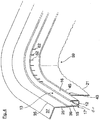
- einen oberen Inneneckbereich eines Türdichtungsaufnahmeteils;
- Fig. 5
- einen unteren Inneneckbereich eines Spülbehälters; und
- Fig. 6
- einen alternativ aufgebauten Türdichtungsbereich, deren Dichtbett unmittelbar durch eine abgestufte Ausprägung in einem Spülbehälter-Mantel in Kombination mit einer Blechleiste ausgebildet ist.
- In der
Fig. 1 ist ein frontseitiger Türdichtungsbereich einer Geschirrspülmaschine gezeigt. Die Geschirrspülmaschine weist einen Spülbehälter 1 auf, der beispielhaft aus einem Blechmantel hergestellt ist, der in einem Blechumformprozess zu dem kastenförmigen Spülbehälter 1 geformt wird. Der in derFig. 1 gezeigte Türdichtungsbereich weist ein gummiartiges Türdichtungselement 7 auf, welches in derFig. 1 im unverformten Zustand sowie lediglich gepunktet dargestellt ist. Das Türdichtungselement 7 erstreckt sich in bekannter Weise in Gerätehochrichtung x (Doppelpfeil) und Geräteseitenrichtung z (Doppelpfeil) oberseitig um die Beschickungsöffnung 9. Bei geschlossener Gerätetür ist die angedeutete Türinnenseite 11 in Dichtkontakt mit der Türdichtung 7. Die Türdichtung 7 ist in einem nutförmig verlaufenden, in der Bautiefenrichtung y (Doppelpfeil) nach vorne offenen Dichtbett 13 eingeschoben. Das Dichtbett 13 weist einen Dichtgrund 12 auf, der über Biegekanten 14 in eine äußere Nutwand 15 sowie eine innere Nutwand 16 übergeht. Das so aufgebaute Dichtbett 13 ist einstückiger Bestandteil eines die Beschickungsöffnung 9 rahmenartig umziehenden Türdichtungsaufnahmeteils 17, welches als ein separates Bauteil unabhängig vom Blechumformprozess des Spülbehälter-Blechmantels vorgeformt wird. Das Türdichtungsaufnahmeteil 17 ist in eine frontseitige und abgestufte Ausprägung 19 des Spülbehälter-Blechmantels eingesetzt. Die abgestufte Ausprägung 19 ist ausgehend von einer Spülbehälterwand 21 durch einen rechtwinklig nach außen abgewinkelten Steg 23 sowie durch einen daran anschließenden Randflansch 25 ausgebildet. Der Randflansch 25 verläuft gemäß derFig. 1 um eine Stufenhöhe a beabstandet sowie parallel zu der Spülbehälterwand 21. Außenseitig ist der Randflansch 25 beispielsweise über eine Schweißverbindung an einem Basisabschnitt 27 eines im Profil U-förmigen Frontrahmens 28 befestigt. Der Frontflansch 28 erstreckt sich in dem vorderen Bereich des Spülbehälters 1 rahmenartig in Form eines umgedrehten U's um dessen beiden Seitenwände sowie Deckwand. - In der, in der
Fig. 1 gezeigten Bauteilanordnung schließt die Vorderkante 31 des Spülbehälter-Blechmantels in etwa bündig mit einem frontseitigen Rahmenschenkel 33 des U-förmigen und den Spülbehälter 1 umziehenden Frontrahmens 28 ab. Die äußere Nutwand 15 des Türdichtungsaufnahmeteils 17 ist um ein Übermaß b (Fig. 2 ) gegenüber der inneren Nutwand 16 in der Bautiefenrichtung y (Doppelpfeil) verlängert und geht frontseitig um eine Sichtkante 35 in einen nach außen abgewinkelten Sichtflansch 37 über. Der Sichtflansch 37 des Türdichtungsaufnahmeteils 17 übergreift daher die zwischen dem Basisabschnitt 27 des den Spülbehälter 1 umziehenden Frontrahmens 28 und der äußeren Nutwand 15 gelegenen Randflansch 25 des Spülbehälter-Blechmantels. In der Bautiefenrichtung y (Doppelpfeil) hinter der Schweißverbindung ist in der äußeren Nutwand 15 eine abgestufte Ausprägung mit einem zurückgesetzten Wandabschnitt 39 eingeprägt. Zwischen dem Wandabschnitt 39 der äußeren Nutwand 15 und dem Randflansch 25 ist ein Dichtstreifen 40 angeordnet, welcher sich bis nahe an eine Übergangskante 41 zwischen dem Randflansch 25 und dem Steg 23 erstreckt. Der Steg 23 ist dabei über eine als Luftspalt ausgebildete Fuge 43 von dem Dichtgrund 12 des Türdichtungsaufnahmeteils 17 beabstandet. Die Fugenbreite d (Fig. 2 ) der Fuge 43 ist ausreichend groß bemessen, so dass sich in der Fuge 43 kein nennenswerter Kapillareffekt ausbildet und durch Luftzufuhr etwaig dort hineingelangte Feuchtigkeit wieder leicht austrocknen kann. Zudem ist die Nutbreite des Dichtbetts 13 so ausgeführt, dass dessen innere Übergangskante 14 sowie eine Stoßkante 45 zwischen dem Steg 23 und der Spülbehälterwand 21 nahezu flächenbündig ineinander übergehen können. - Zweckmäßigerweise ist das Türdichtungsaufnahmeteil 17 über seine äußere Nutwand 15 mit dem Randflansch 25 der abgestuften Ausprägung der Spülbehälterwand fest verbunden. Insbesondere sind die Außenseite der Nutwand 15 des Türdichtungsaufnahmeteils 17 und die Innenseite des Randflanschs 25 der abgestuften Ausprägung 19 der Spülbehälterwand 21 punktuell an vorgegebenen Stellen der U-förmigen Erstreckung des Türdichtungsaufnahmeteils 17 oder durchgängig miteinander verschweißt.
- Zweckmäßigerweise sind die äußere Nutwand 15 und der Randflansch 25 in einem Bereich miteinander fest verbunden, der außerhalb des Nassbereichs des Spülbehälters, das heißt in einem im Spülbetrieb der Geschirrspülmaschine weitgehend trocken bleibenden Außenbereich zwischen der Türdichtung 7 und der Beschickungsöffnung 9 liegt. In der
Fig. 1 ist die örtliche Lage des außenliegenden Endabschnitts der Türdichtung 7, an dem die Tür in ihrer Schließstellung anliegt, durch eine gestrichelte Linie 9' indiziert. Somit sind Probleme mit Kapillarspaltkorrosion in dem Verbindungsabschnitt zwischen der äußeren Nutwand 15 und dem Randflansch 25 weitgehend vermieden. Diese Art der Verbindung ist von der konkreten Ausführungsvariante vonFig. 1 unabhängig und ist selbstverständlich auch bei anderen Ausführungsformen der Erfindung vorteilhaft. - Der Spülbehälter-Blechmantel ist erfindungsgemäß aus einem, eine reduzierte Korrosionsfestigkeit aufweisenden Cr-Stahlblech gefertigt, während das Türdichtungsaufnahmeteil 17 aus einem CrNi-Stahlblech mit erhöhter Korrosionsbeständigkeit hergestellt ist.
- In der
Fig. 2 ist mit gestrichelter Linie ein Türsensor 47 angedeutet, welcher in Einbaulage an einer die Beschickungsöffnung 9 oberseitig begrenzenden Querleiste 48 des den Spülbehälter 1 (Fig. 1 ) umziehenden Frontrahmens 28 gehaltert ist. Der Türsensor 47 ist vorliegend ein Hall-Sensor, dessen Sensorfläche unmittelbar auf einen nach innen eingezogenen Formabschnitt 49 der äußeren Nutwand 15 aufliegt. Der Türsensor 47 erstreckt sich daher in der Gerätehochrichtung z (Doppelpfeil) durch eine erste Montageöffnung in dem Basisabschnitt 27 des den Spülbehälter 1 (Fig. 1 ) umziehenden Frontrahmens 28 sowie durch eine zweite Montageöffnung 53 des Randflanschs 25 des Spülbehälter-Blechmantels. Der Türsensor 47 ist somit mit ausreichendem Abstand zu dem Blechmaterial des Spülbehälters angeordnet, so dass es trotz der Fertigung des Spülbehälter-Blechmantels aus ferromagnetischem Stahl, etwa Cr-Stahl, es zu keiner Funktionsbeeinträchtigung des Hall-Sensors 47 kommt, der bei einem Öffnen/Schließen der Gerätetür Magnetfeldänderungen erfassen kann. - In der
Fig. 3 ist ein seitlich versetzt zu dem vorgenannten Hall-Sensor 47 angeordneter Schlossdurchbruch 55 gezeigt, durch den sich ein nicht dargestellter Haltebügel eines in dem den Spülbehälter 1 (Fig. 1 ) umziehenden Frontrahmen 28 gehalterten Türschlosses bis in die Bewegungsbahn der Gerätetür hinein erstrecken kann. Der Schlossdurchbruch 55 besteht gemäß derFig. 3 aus drei in der Hochrichtung z (Doppelpfeil) übereinander angeordneten Materialaussparungen, die jeweils in etwa fluchtend in dem Basisabschnitt 27 des den Spülbehälter 1 (Fig. 1 ) umziehenden Frontrahmens 28, in dem Randflansch 25 sowie in der äußeren Nutwand 15 des Türdichtungsaufnahmeteils 17 angeordnet sind. Die in dem Türdichtungsaufnahmeteil 17 vorgesehene Materialaussparung 57 ist durch einen hochgezogenen Blechrand 58 begrenzt, dessen Oberkante in Anlage mit dem Aussparungsrand des Basisabschnitts 27 des den Spülbehälter 1 (Fig. 1 ) umziehenden Frontrahmens 28 ist. Auf diese Weise ist die Schweißverbindungsstelle nach außen hin mit Hilfe des hochgezogenen Blechrands 58 geschlossen. - In der
Fig. 4 ist ein Inneneckbereich 59 des Türdichtungsaufnahmeteils 17 dargestellt. Daraus geht hervor, dass das Türdichtungsaufnahmeteil 17 mit konstantem Profil durch den Eckbereich 59 verläuft. Gemäß derFig. 4 sind in dem gefalzten Ende 61 der inneren Nutwand 16 Entlastungsschlitze 62 vorgesehen. Mittels der Entlastungsschlitze 62 können Materialspannungen, die während des Umformprozesses auftreten, reduziert werden, wodurch sich auch bei geringer Wandstärke des Türdichtungsaufnahmeteils 17 keine Materialreißer ergeben. - In der
Fig. 5 ist ein unterer Eckbereich 63 an dem Übergang einer Spülbehälterseitenwand 21 in den vorderen Schürzenbereich 65 dargestellt. Der Randflansch 25 des Spülbehälter-Blechmantels erweitert sich demzufolge in der Bautiefenrichtung y (Doppelpfeil) nach vorn bis zu der Vorderkante der Behälterschürze 65. Zudem weist das Türdichtungsaufnahmeteil 17 gemäß derFig. 5 in dem gezeigten Eckbereich 63 einen freien Endabschnitt 66 auf, bei dem die äußere Nutwand 15 über eine Bauteilhöhe e um einen nach unten offenen Luftspalt 67 von dem Randflansch 25 des Spülbehälter-Blechmantels beabstandet ist. Das Spaltmaß des Luftspalts 67 ist derart groß bemessen, dass sich keine Kapillarwirkung in dem Luftspalt ergibt. - In der
Fig. 6 ist ein alternativer Türdichtungsbereich gezeigt, dessen Dichtbett 13 zwischen einer Dichtschiene 69 sowie dem Spülbehälter-Blechmantel ausgebildet ist. Die Blechteilgeometrie des Spülbehälter-Blechmantels ist dabei identisch mit der in den vorangegangenen Figuren gezeigten, nach außen abgestuften Ausprägung 19. Im Rahmen einer Großserienproduktion kann daher der Spülbehälter 1 in einer Grundausführung vorgehalten werden. Je nach Spülbehälter-Variante kann die Dichtschiene 69 oder aber das Türdichtungsaufnahmeteil 17 in dem Spülbehälter 1 eingebaut werden. Bei Verbau der Dichtschiene 69 wird diese an einem seitlich nach außen versetzten Wandabschnitt 71 mittels Punktschweißung befestigt. Die Stufenhöhe des Wandabschnitts 71 ist derart bemessen, dass sich zwischen der Spülbehälterwand 21 und der Dichtschiene 69 ein flächenbündiger Übergang ergibt. In dem in derFig. 6 gezeigten Fall wird das Dichtbett 13 also unmittelbar durch den Steg 23 sowie den Randflansch 25 der abgestuften Ausprägung 19 in dem Spülbehälter-Blechmantel gebildet. Die in derFig. 6 gezeigte Variante ist insbesondere dann anwendbar, wenn sowohl der Spülbehälter-Blechmantel als auch die Dichtschiene 69 aus einem hochwertigen korrosionsbeständigen Stahl, etwa CrNi-Stahl hergestellt ist. Demgegenüber ist die in denFig. 1 bis 5 gezeigte Variante insbesondere dann anwendbar, wenn zur Reduzierung von Materialkosten der Spülbehälter-Blechmantel aus einem Stahlblech mit reduzierter Korrosionsfestigkeit hergestellt ist, während der besonders korrosionsanfällige Türdichtungsbereich durch das beispielsweise aus CrNi-Stahl gefertigte Türdichtungsaufnahmeteil 17 bereitgestellt wird. -
- 1
- Spülbehälter
- 7
- Türdichtung
- 9
- Beschickungsöffnung
- 11
- Türinnenseite
- 12
- Dichtgrund
- 13
- Dichtbett
- 14
- Biegekanten
- 15
- Äußere Nutwand
- 16
- Innere Nutwand
- 17
- Türdichtungsaufnahmeteil
- 19
- Abgestufte Ausprägung
- 21
- Spülbehälterwand
- 23
- Steg
- 25
- Randflansch
- 27
- Basisabschnitt
- 28
- Frontrahmen
- 31
- Vorderkante des Spülbehälter-Blechmantels
- 33
- Rahmenschenkel des Frontrahmens
- 35
- Sichtkante
- 37
- Sichtflansch
- 39
- Zurückgesetzter Wandabschnitt
- 40
- Dichtstreifen
- 41
- Übergangskante
- 43
- Fuge
- 45
- Stoßkante
- 47
- Türsensor
- 48
- Querleiste des Frontrahmens
- 49
- Formabschnitt
- 51
- Materialaussparung
- 53
- Materialaussparung
- 55
- Schlossdurchbruch
- 57
- Materialaussparung
- 58
- hochgezogener Blechrand
- 59
- Inneneckbereich
- 61
- Gefalztes Ende
- 62
- Entlastungsschlitze
- 63
- Bodenseitiger Eckbereich
- 65
- Behälterschürze
- 66
- Freier Endabschnitt
- 67
- Luftspalt
- 69
- Dichtschiene
- 71
- Wandabschnitt
- a
- Stufenhöhe
- b
- Versatzmaß
- d
- Fugenbreite
- e
- Bauhöhe
- x
- Raumrichtung; Gerätehochrichtung (Doppelpfeil)
- y
- Raumrichtung; Bautiefenrichtung (Doppelpfeil)
- z
- Raumrichtung; Geräteseitenrichtung (Doppelpfeil)
Claims (14)
- Geschirrspülmaschine, insbesondere Haushaltsgeschirrspülmaschine, mit einem Spülbehälter (1), dessen Beschickungsöffnung (9) zumindest teilweise von einer Türdichtung (7) umzogen ist, die in ein Türdichtungsaufnahmeteil (17) eingesetzt ist, welches mit dem Spülbehälter (1) verbunden ist, wobei zumindest eine Spülbehälterwand (21) eine frontseitig nach außen abgestufte Ausprägung (19) aufweist, bei welcher die Spülbehälterwand (21) über einen abgewinkelten Steg (23) in einen um eine Stufenhöhe (a) nach außen versetzten Randflansch (25) übergeht, und wobei das Türdichtungsaufnahmeteil (17) konturangepasst in die nach außen abgestufte Ausprägung (19) der Spülbehälterwand (21) eingesetzt ist,
dadurch gekennzeichnet,
dass das Türdichtungsaufnahmeteil (17) unter Zwischenlage des Randflanschs (25) der abgestuften Ausprägung (19) der Spülbehälterwand (21) an einem den Spülbehälter (1) umziehenden Frontrahmen (28) angeordnet ist, so dass im Bereich der frontseitigen Beschickungsöffnung sich ein dreilagiger Blechteilverbund ergibt. - Geschirrspülmaschine nach Anspruch 1, dadurch gekennzeichnet, dass das Türdichtungsaufnahmeteil (17) ein nutförmiges Dichtbett (13) mit einem Dichtgrund (12) sowie mit einer inneren Nutwand (16) und mit einer äußeren Nutwand (15) aufweist.
- Geschirrspülmaschine nach Anspruch 2, dadurch gekennzeichnet, dass das Dichtbett (13) des Türdichtungsaufnahmeteils (17) in der Bautiefenrichtung (y) um ein Versatzmaß (b) hinter einer Vorderkante (31) der Spülbehälterwand (21) angeordnet ist.
- Geschirrspülmaschine nach Anspruch 2 oder 3, dadurch gekennzeichnet, dass das Türdichtungsaufnahmeteil (17) über seine äußere Nutwand (15) mit dem Randflansch (25) der abgestuften Ausprägung (19) der Spülbehälterwand (21) verbunden ist, insbesondere über eine Schweißverbindung.
- Geschirrspülmaschine nach Anspruch 2, 3 oder 4, dadurch gekennzeichnet, dass die äußere Nutwand (15) des Türdichtungsaufnahmeteils (17) um ein Übermaß (b) über die innere Nutwand (16) hinaus verlängert ist, und/oder dass die äußere Nutwand (15) frontseitig in einen nach außen abgewinkelten Sichtflansch (37) übergeht, der die Vorderkante (31) der Spülbehälterwand (21) umgreift und/oder in Anlage mit dem den Spülbehälter (1) umziehenden Frontrahmen (28) ist.
- Geschirrspülmaschine nach einem der vorhergehenden Ansprüche, dadurch gekennzeichnet, dass ein Dichtgrund (12) des Türdichtungsaufnahmeteils (17) über eine Fuge (43) von dem abgewinkelten Steg (23) der abgestuften Ausprägung (19) der Spülbehälterwand (21) beabstandet ist.
- Geschirrspülmaschine nach einem der Ansprüche 2 bis 6, dadurch gekennzeichnet, dass die Nutbreite des Dichtbetts (13) im Wesentlichen der Stufenhöhe (a) der abgestuften Ausprägung (19) der Spülbehälterwand (21) entspricht.
- Geschirrspülmaschine nach einem der vorhergehenden Ansprüche, dadurch gekennzeichnet, dass zwischen dem Türdichtungsaufnahmeteil (17) und der Spülbehälterwand (21), insbesondere zwischen der äußeren Nutwand (15) des Türdichtungsaufnahmeteils (17) und dem Randflansch (25) der Spülbehälterwand (21) ein Dichtelement (40) vorgesehen ist.
- Geschirrspülmaschine nach Anspruch 8, dadurch gekennzeichnet, dass die äußere Nutwand (15) des Dichtbetts (13) einen von dem Randflansch (25) der Spülbehälterwand (21) zurückgesetzten Wandbereich (39) aufweist, der einen freien Spalt definiert, in dem das Dichtungselement (40) angeordnet ist.
- Geschirrspülmaschine nach einem der vorhergehenden Ansprüche, dadurch gekennzeichnet, dass das Türdichtungsaufnahmeteil (17), insbesondere durchgängig U-förmig oder zwei- oder mehrteilig U-förmig zusammengesetzt, um die Beschickungsöffnung (9) der Geschirrspülmaschine läuft, und dass das Türdichtungsaufnahmeteil (17) bodenseitig einen freien Endabschnitt (66) aufweist, in dem die äußere Nutwand (15) des Dichtbetts (13) um einen Luftspalt (67) von dem Randflansch (25) der abgestuften Ausprägung (19) der Spülbehälterwand (21) beabstandet ist.
- Geschirrspülmaschine nach einem der vorhergehenden Ansprüche, dadurch gekennzeichnet, dass sich das Türdichtungsaufnahmeteil (17) durchgängig über die oberen Eckbereiche (59) der Geschirrspülmaschine erstreckt.
- Geschirrspülmaschine nach Anspruch 11, dadurch gekennzeichnet, dass das Türdichtungsaufnahmeteil (17) in den Eckbereichen (59) Entlastungsschlitze (62) aufweist.
- Geschirrspülmaschine nach einem der vorhergehenden Ansprüche, dadurch gekennzeichnet, dass das Türdichtungsaufnahmeteil (17) aus einem korrosionsfesten Stahlblech, insbesondere CrNi-Stahl, und der Spülbehälter aus einem weniger korrosionsbeständigen Stahlblech, insbesondere Cr-Stahl, hergestellt ist.
- Geschirrspülmaschine nach einem der vorhergehenden Ansprüche, dadurch gekennzeichnet, dass der abgewinkelte Steg (23) der Spülbehälterwand (21) durch eine Fuge (43) von dem Dichtgrund (12) des Türdichtungsaufnahmeteils (17) beabstandet ist.
Priority Applications (1)
| Application Number | Priority Date | Filing Date | Title |
|---|---|---|---|
| PL11192564T PL2465402T3 (pl) | 2010-12-15 | 2011-12-08 | Zmywarka do naczyń |
Applications Claiming Priority (1)
| Application Number | Priority Date | Filing Date | Title |
|---|---|---|---|
| DE201010063105 DE102010063105A1 (de) | 2010-12-15 | 2010-12-15 | Geschirrspülmaschine |
Publications (3)
| Publication Number | Publication Date |
|---|---|
| EP2465402A2 EP2465402A2 (de) | 2012-06-20 |
| EP2465402A3 EP2465402A3 (de) | 2017-06-28 |
| EP2465402B1 true EP2465402B1 (de) | 2018-08-08 |
Family
ID=45318924
Family Applications (1)
| Application Number | Title | Priority Date | Filing Date |
|---|---|---|---|
| EP11192564.0A Active EP2465402B1 (de) | 2010-12-15 | 2011-12-08 | Geschirrspülmaschine |
Country Status (3)
| Country | Link |
|---|---|
| EP (1) | EP2465402B1 (de) |
| DE (1) | DE102010063105A1 (de) |
| PL (1) | PL2465402T3 (de) |
Families Citing this family (2)
| Publication number | Priority date | Publication date | Assignee | Title |
|---|---|---|---|---|
| CN107510426B (zh) * | 2016-06-15 | 2023-12-26 | 青岛海尔洗碗机有限公司 | 密封结构、洗碗机内胆及洗碗机 |
| FR3075585B1 (fr) * | 2017-12-21 | 2021-10-01 | Groupe Brandt | Lave-vaisselle a joint d'etancheite entre la cuve de lavage et la porte de facade |
Family Cites Families (7)
| Publication number | Priority date | Publication date | Assignee | Title |
|---|---|---|---|---|
| DE7520122U (de) * | 1975-06-25 | 1976-04-01 | Bosch-Siemens Hausgeraete Gmbh, 7000 Stuttgart | Behaelter, insbesondere fuer geschirrspuelmaschinen o.dgl. |
| IT7934041U1 (it) * | 1979-12-10 | 1981-06-10 | Zanussi A Spa Industrie | Vasca metallica per lavastoviglie. |
| DE8027936U1 (de) * | 1980-10-20 | 1981-02-05 | Bosch-Siemens Hausgeraete Gmbh, 7000 Stuttgart | Tuerdichtung fuer geschirrspuelmaschinen |
| DE102005062478A1 (de) | 2005-12-27 | 2007-07-05 | BSH Bosch und Siemens Hausgeräte GmbH | Geschirrspülmaschine mit einer Behälterhaube aus preiswertem Stahl |
| DE102007031886B4 (de) * | 2007-07-09 | 2020-09-24 | BSH Hausgeräte GmbH | Haushaltsgerät mit selbstdiagosefähger Türschlossstellungs-Erfassungseinrichtung |
| DE102007041314B4 (de) * | 2007-08-31 | 2014-08-21 | BSH Bosch und Siemens Hausgeräte GmbH | Verfahren zur Herstellung eines wasserführenden Haushaltsgeräts sowie wasserführendes Haushaltsgerät |
| DE102010039722A1 (de) * | 2010-08-24 | 2012-03-01 | BSH Bosch und Siemens Hausgeräte GmbH | Geschirrspülmaschine |
-
2010
- 2010-12-15 DE DE201010063105 patent/DE102010063105A1/de not_active Withdrawn
-
2011
- 2011-12-08 PL PL11192564T patent/PL2465402T3/pl unknown
- 2011-12-08 EP EP11192564.0A patent/EP2465402B1/de active Active
Non-Patent Citations (1)
| Title |
|---|
| None * |
Also Published As
| Publication number | Publication date |
|---|---|
| DE102010063105A1 (de) | 2012-06-21 |
| EP2465402A3 (de) | 2017-06-28 |
| EP2465402A2 (de) | 2012-06-20 |
| PL2465402T3 (pl) | 2019-02-28 |
Similar Documents
| Publication | Publication Date | Title |
|---|---|---|
| DE102012208348B4 (de) | Fahrzeug-Stossfänger | |
| EP2830475B1 (de) | Sprüharm für einen geschirrspüler mit zwei sprüharmteilen | |
| DE102007030064A1 (de) | Plattform für eine Geschirrspülmaschine | |
| EP2378945B1 (de) | Geschirrspülmaschine | |
| EP2094895A1 (de) | Wasserführendes haushaltsgerät mit einem aus zumindest zwei bauteilen zusammengesetzten behandlungsbehälter | |
| EP1971251A1 (de) | Geschirrspülmaschine mit einer behälterhaube aus preiswertem stahl, einem rahmenteil aus hochwertigem stahl und einer spülwanne aus kunststoff | |
| EP1945090B1 (de) | Geschirrspülmaschine mit einem an einem behandlungsbehälter befestigten rahmenteil aus kunststoff | |
| EP2422680A2 (de) | Geschirrspülmaschine | |
| EP2465402A2 (de) | Geschirrspülmaschine | |
| EP2465403A2 (de) | Geschirrspülmaschine | |
| DE102009001897B4 (de) | Geschirrspülmaschine mit einem Spülbehälter | |
| DE102011004691B4 (de) | Verbindungsstruktur | |
| DE102011003821B4 (de) | Geschirrspülmaschine, insbesondere Haushaltsgeschirrspülmaschine | |
| WO2007020241A2 (de) | Plattform für eine geschirrspülmaschine | |
| DE102017203978B4 (de) | Haushaltsgeschirrspülmaschine | |
| EP1674027B1 (de) | Geschirrspülmaschine mit einem schubladenartig aus dem Gehäuse ausziehbaren Spülbehälter | |
| EP2484265A2 (de) | Verfahren zur Herstellung einer Geschirrspülmaschine und Geschirrspülmaschine | |
| DE102011004056A1 (de) | Geschirrspülmaschine und Verfahren zum Herstellen eines Spülbehälters einer Geschirrspülmaschine | |
| EP2446798A2 (de) | Geschirrspülmaschine mit einer verbesserten Kederanordnung | |
| EP3629874B1 (de) | Spülbehälter, haushaltsgeschirrspülmaschine und verfahren | |
| DE3541758C2 (de) | ||
| DE102008041048B4 (de) | Geschirrspülmaschine zum Einbau in einen Einbauschrank | |
| DE202009010794U1 (de) | Kältegerät | |
| DE10313706B4 (de) | Entwässerungsanordnung für eine Fahrzeugtür | |
| DE102011086782B3 (de) | Geschirrspülmaschine, insbesondere Haushaltsgeschirrspülmaschine |
Legal Events
| Date | Code | Title | Description |
|---|---|---|---|
| PUAI | Public reference made under article 153(3) epc to a published international application that has entered the european phase |
Free format text: ORIGINAL CODE: 0009012 |
|
| AK | Designated contracting states |
Kind code of ref document: A2 Designated state(s): AL AT BE BG CH CY CZ DE DK EE ES FI FR GB GR HR HU IE IS IT LI LT LU LV MC MK MT NL NO PL PT RO RS SE SI SK SM TR |
|
| AX | Request for extension of the european patent |
Extension state: BA ME |
|
| RAP1 | Party data changed (applicant data changed or rights of an application transferred) |
Owner name: BSH HAUSGERAETE GMBH |
|
| PUAL | Search report despatched |
Free format text: ORIGINAL CODE: 0009013 |
|
| AK | Designated contracting states |
Kind code of ref document: A3 Designated state(s): AL AT BE BG CH CY CZ DE DK EE ES FI FR GB GR HR HU IE IS IT LI LT LU LV MC MK MT NL NO PL PT RO RS SE SI SK SM TR |
|
| AX | Request for extension of the european patent |
Extension state: BA ME |
|
| RIC1 | Information provided on ipc code assigned before grant |
Ipc: A47L 15/42 20060101AFI20170522BHEP |
|
| 17P | Request for examination filed |
Effective date: 20180102 |
|
| RBV | Designated contracting states (corrected) |
Designated state(s): AL AT BE BG CH CY CZ DE DK EE ES FI FR GB GR HR HU IE IS IT LI LT LU LV MC MK MT NL NO PL PT RO RS SE SI SK SM TR |
|
| GRAP | Despatch of communication of intention to grant a patent |
Free format text: ORIGINAL CODE: EPIDOSNIGR1 |
|
| INTG | Intention to grant announced |
Effective date: 20180321 |
|
| GRAS | Grant fee paid |
Free format text: ORIGINAL CODE: EPIDOSNIGR3 |
|
| GRAA | (expected) grant |
Free format text: ORIGINAL CODE: 0009210 |
|
| AK | Designated contracting states |
Kind code of ref document: B1 Designated state(s): AL AT BE BG CH CY CZ DE DK EE ES FI FR GB GR HR HU IE IS IT LI LT LU LV MC MK MT NL NO PL PT RO RS SE SI SK SM TR |
|
| REG | Reference to a national code |
Ref country code: GB Ref legal event code: FG4D Free format text: NOT ENGLISH |
|
| REG | Reference to a national code |
Ref country code: CH Ref legal event code: EP Ref country code: AT Ref legal event code: REF Ref document number: 1026037 Country of ref document: AT Kind code of ref document: T Effective date: 20180815 |
|
| REG | Reference to a national code |
Ref country code: IE Ref legal event code: FG4D Free format text: LANGUAGE OF EP DOCUMENT: GERMAN |
|
| REG | Reference to a national code |
Ref country code: DE Ref legal event code: R096 Ref document number: 502011014559 Country of ref document: DE |
|
| REG | Reference to a national code |
Ref country code: NL Ref legal event code: MP Effective date: 20180808 |
|
| REG | Reference to a national code |
Ref country code: LT Ref legal event code: MG4D |
|
| PG25 | Lapsed in a contracting state [announced via postgrant information from national office to epo] |
Ref country code: BG Free format text: LAPSE BECAUSE OF FAILURE TO SUBMIT A TRANSLATION OF THE DESCRIPTION OR TO PAY THE FEE WITHIN THE PRESCRIBED TIME-LIMIT Effective date: 20181108 Ref country code: NL Free format text: LAPSE BECAUSE OF FAILURE TO SUBMIT A TRANSLATION OF THE DESCRIPTION OR TO PAY THE FEE WITHIN THE PRESCRIBED TIME-LIMIT Effective date: 20180808 Ref country code: SE Free format text: LAPSE BECAUSE OF FAILURE TO SUBMIT A TRANSLATION OF THE DESCRIPTION OR TO PAY THE FEE WITHIN THE PRESCRIBED TIME-LIMIT Effective date: 20180808 Ref country code: LT Free format text: LAPSE BECAUSE OF FAILURE TO SUBMIT A TRANSLATION OF THE DESCRIPTION OR TO PAY THE FEE WITHIN THE PRESCRIBED TIME-LIMIT Effective date: 20180808 Ref country code: FI Free format text: LAPSE BECAUSE OF FAILURE TO SUBMIT A TRANSLATION OF THE DESCRIPTION OR TO PAY THE FEE WITHIN THE PRESCRIBED TIME-LIMIT Effective date: 20180808 Ref country code: RS Free format text: LAPSE BECAUSE OF FAILURE TO SUBMIT A TRANSLATION OF THE DESCRIPTION OR TO PAY THE FEE WITHIN THE PRESCRIBED TIME-LIMIT Effective date: 20180808 Ref country code: GR Free format text: LAPSE BECAUSE OF FAILURE TO SUBMIT A TRANSLATION OF THE DESCRIPTION OR TO PAY THE FEE WITHIN THE PRESCRIBED TIME-LIMIT Effective date: 20181109 Ref country code: IS Free format text: LAPSE BECAUSE OF FAILURE TO SUBMIT A TRANSLATION OF THE DESCRIPTION OR TO PAY THE FEE WITHIN THE PRESCRIBED TIME-LIMIT Effective date: 20181208 Ref country code: NO Free format text: LAPSE BECAUSE OF FAILURE TO SUBMIT A TRANSLATION OF THE DESCRIPTION OR TO PAY THE FEE WITHIN THE PRESCRIBED TIME-LIMIT Effective date: 20181108 |
|
| PG25 | Lapsed in a contracting state [announced via postgrant information from national office to epo] |
Ref country code: AL Free format text: LAPSE BECAUSE OF FAILURE TO SUBMIT A TRANSLATION OF THE DESCRIPTION OR TO PAY THE FEE WITHIN THE PRESCRIBED TIME-LIMIT Effective date: 20180808 Ref country code: HR Free format text: LAPSE BECAUSE OF FAILURE TO SUBMIT A TRANSLATION OF THE DESCRIPTION OR TO PAY THE FEE WITHIN THE PRESCRIBED TIME-LIMIT Effective date: 20180808 Ref country code: LV Free format text: LAPSE BECAUSE OF FAILURE TO SUBMIT A TRANSLATION OF THE DESCRIPTION OR TO PAY THE FEE WITHIN THE PRESCRIBED TIME-LIMIT Effective date: 20180808 |
|
| PG25 | Lapsed in a contracting state [announced via postgrant information from national office to epo] |
Ref country code: IT Free format text: LAPSE BECAUSE OF FAILURE TO SUBMIT A TRANSLATION OF THE DESCRIPTION OR TO PAY THE FEE WITHIN THE PRESCRIBED TIME-LIMIT Effective date: 20180808 Ref country code: EE Free format text: LAPSE BECAUSE OF FAILURE TO SUBMIT A TRANSLATION OF THE DESCRIPTION OR TO PAY THE FEE WITHIN THE PRESCRIBED TIME-LIMIT Effective date: 20180808 Ref country code: RO Free format text: LAPSE BECAUSE OF FAILURE TO SUBMIT A TRANSLATION OF THE DESCRIPTION OR TO PAY THE FEE WITHIN THE PRESCRIBED TIME-LIMIT Effective date: 20180808 Ref country code: CZ Free format text: LAPSE BECAUSE OF FAILURE TO SUBMIT A TRANSLATION OF THE DESCRIPTION OR TO PAY THE FEE WITHIN THE PRESCRIBED TIME-LIMIT Effective date: 20180808 Ref country code: ES Free format text: LAPSE BECAUSE OF FAILURE TO SUBMIT A TRANSLATION OF THE DESCRIPTION OR TO PAY THE FEE WITHIN THE PRESCRIBED TIME-LIMIT Effective date: 20180808 |
|
| REG | Reference to a national code |
Ref country code: DE Ref legal event code: R097 Ref document number: 502011014559 Country of ref document: DE |
|
| PG25 | Lapsed in a contracting state [announced via postgrant information from national office to epo] |
Ref country code: SK Free format text: LAPSE BECAUSE OF FAILURE TO SUBMIT A TRANSLATION OF THE DESCRIPTION OR TO PAY THE FEE WITHIN THE PRESCRIBED TIME-LIMIT Effective date: 20180808 Ref country code: DK Free format text: LAPSE BECAUSE OF FAILURE TO SUBMIT A TRANSLATION OF THE DESCRIPTION OR TO PAY THE FEE WITHIN THE PRESCRIBED TIME-LIMIT Effective date: 20180808 Ref country code: SM Free format text: LAPSE BECAUSE OF FAILURE TO SUBMIT A TRANSLATION OF THE DESCRIPTION OR TO PAY THE FEE WITHIN THE PRESCRIBED TIME-LIMIT Effective date: 20180808 |
|
| PLBE | No opposition filed within time limit |
Free format text: ORIGINAL CODE: 0009261 |
|
| STAA | Information on the status of an ep patent application or granted ep patent |
Free format text: STATUS: NO OPPOSITION FILED WITHIN TIME LIMIT |
|
| 26N | No opposition filed |
Effective date: 20190509 |
|
| REG | Reference to a national code |
Ref country code: CH Ref legal event code: PL |
|
| GBPC | Gb: european patent ceased through non-payment of renewal fee |
Effective date: 20181208 |
|
| PG25 | Lapsed in a contracting state [announced via postgrant information from national office to epo] |
Ref country code: SI Free format text: LAPSE BECAUSE OF FAILURE TO SUBMIT A TRANSLATION OF THE DESCRIPTION OR TO PAY THE FEE WITHIN THE PRESCRIBED TIME-LIMIT Effective date: 20180808 Ref country code: LU Free format text: LAPSE BECAUSE OF NON-PAYMENT OF DUE FEES Effective date: 20181208 Ref country code: MC Free format text: LAPSE BECAUSE OF FAILURE TO SUBMIT A TRANSLATION OF THE DESCRIPTION OR TO PAY THE FEE WITHIN THE PRESCRIBED TIME-LIMIT Effective date: 20180808 |
|
| REG | Reference to a national code |
Ref country code: IE Ref legal event code: MM4A |
|
| REG | Reference to a national code |
Ref country code: BE Ref legal event code: MM Effective date: 20181231 |
|
| PG25 | Lapsed in a contracting state [announced via postgrant information from national office to epo] |
Ref country code: IE Free format text: LAPSE BECAUSE OF NON-PAYMENT OF DUE FEES Effective date: 20181208 Ref country code: FR Free format text: LAPSE BECAUSE OF NON-PAYMENT OF DUE FEES Effective date: 20181231 |
|
| PG25 | Lapsed in a contracting state [announced via postgrant information from national office to epo] |
Ref country code: BE Free format text: LAPSE BECAUSE OF NON-PAYMENT OF DUE FEES Effective date: 20181231 |
|
| PG25 | Lapsed in a contracting state [announced via postgrant information from national office to epo] |
Ref country code: LI Free format text: LAPSE BECAUSE OF NON-PAYMENT OF DUE FEES Effective date: 20181231 Ref country code: CH Free format text: LAPSE BECAUSE OF NON-PAYMENT OF DUE FEES Effective date: 20181231 Ref country code: GB Free format text: LAPSE BECAUSE OF NON-PAYMENT OF DUE FEES Effective date: 20181208 |
|
| PG25 | Lapsed in a contracting state [announced via postgrant information from national office to epo] |
Ref country code: MT Free format text: LAPSE BECAUSE OF FAILURE TO SUBMIT A TRANSLATION OF THE DESCRIPTION OR TO PAY THE FEE WITHIN THE PRESCRIBED TIME-LIMIT Effective date: 20180808 |
|
| REG | Reference to a national code |
Ref country code: AT Ref legal event code: MM01 Ref document number: 1026037 Country of ref document: AT Kind code of ref document: T Effective date: 20181208 |
|
| PG25 | Lapsed in a contracting state [announced via postgrant information from national office to epo] |
Ref country code: AT Free format text: LAPSE BECAUSE OF NON-PAYMENT OF DUE FEES Effective date: 20181208 |
|
| PG25 | Lapsed in a contracting state [announced via postgrant information from national office to epo] |
Ref country code: PT Free format text: LAPSE BECAUSE OF FAILURE TO SUBMIT A TRANSLATION OF THE DESCRIPTION OR TO PAY THE FEE WITHIN THE PRESCRIBED TIME-LIMIT Effective date: 20180808 |
|
| PG25 | Lapsed in a contracting state [announced via postgrant information from national office to epo] |
Ref country code: HU Free format text: LAPSE BECAUSE OF FAILURE TO SUBMIT A TRANSLATION OF THE DESCRIPTION OR TO PAY THE FEE WITHIN THE PRESCRIBED TIME-LIMIT; INVALID AB INITIO Effective date: 20111208 Ref country code: MK Free format text: LAPSE BECAUSE OF NON-PAYMENT OF DUE FEES Effective date: 20180808 Ref country code: CY Free format text: LAPSE BECAUSE OF FAILURE TO SUBMIT A TRANSLATION OF THE DESCRIPTION OR TO PAY THE FEE WITHIN THE PRESCRIBED TIME-LIMIT Effective date: 20180808 |
|
| REG | Reference to a national code |
Ref country code: DE Ref legal event code: R084 Ref document number: 502011014559 Country of ref document: DE |
|
| PGFP | Annual fee paid to national office [announced via postgrant information from national office to epo] |
Ref country code: TR Payment date: 20251202 Year of fee payment: 15 |
|
| PGFP | Annual fee paid to national office [announced via postgrant information from national office to epo] |
Ref country code: PL Payment date: 20251128 Year of fee payment: 15 |
|
| PGFP | Annual fee paid to national office [announced via postgrant information from national office to epo] |
Ref country code: DE Payment date: 20251231 Year of fee payment: 15 |