EP2464591B1 - Élément coulissant et dispositif télescopique comportant un tel élément coulissant - Google Patents
Élément coulissant et dispositif télescopique comportant un tel élément coulissant Download PDFInfo
- Publication number
- EP2464591B1 EP2464591B1 EP10833664.5A EP10833664A EP2464591B1 EP 2464591 B1 EP2464591 B1 EP 2464591B1 EP 10833664 A EP10833664 A EP 10833664A EP 2464591 B1 EP2464591 B1 EP 2464591B1
- Authority
- EP
- European Patent Office
- Prior art keywords
- sliding element
- telescopic
- feeding channel
- sliding
- lubricant
- Prior art date
- Legal status (The legal status is an assumption and is not a legal conclusion. Google has not performed a legal analysis and makes no representation as to the accuracy of the status listed.)
- Not-in-force
Links
Images

Classifications
-
- B—PERFORMING OPERATIONS; TRANSPORTING
- B66—HOISTING; LIFTING; HAULING
- B66C—CRANES; LOAD-ENGAGING ELEMENTS OR DEVICES FOR CRANES, CAPSTANS, WINCHES, OR TACKLES
- B66C23/00—Cranes comprising essentially a beam, boom, or triangular structure acting as a cantilever and mounted for translatory of swinging movements in vertical or horizontal planes or a combination of such movements, e.g. jib-cranes, derricks, tower cranes
- B66C23/62—Constructional features or details
- B66C23/64—Jibs
- B66C23/70—Jibs constructed of sections adapted to be assembled to form jibs or various lengths
- B66C23/701—Jibs constructed of sections adapted to be assembled to form jibs or various lengths telescopic
- B66C23/707—Jibs constructed of sections adapted to be assembled to form jibs or various lengths telescopic guiding devices for telescopic jibs
-
- F—MECHANICAL ENGINEERING; LIGHTING; HEATING; WEAPONS; BLASTING
- F16—ENGINEERING ELEMENTS AND UNITS; GENERAL MEASURES FOR PRODUCING AND MAINTAINING EFFECTIVE FUNCTIONING OF MACHINES OR INSTALLATIONS; THERMAL INSULATION IN GENERAL
- F16C—SHAFTS; FLEXIBLE SHAFTS; ELEMENTS OR CRANKSHAFT MECHANISMS; ROTARY BODIES OTHER THAN GEARING ELEMENTS; BEARINGS
- F16C29/00—Bearings for parts moving only linearly
- F16C29/02—Sliding-contact bearings
-
- F—MECHANICAL ENGINEERING; LIGHTING; HEATING; WEAPONS; BLASTING
- F16—ENGINEERING ELEMENTS AND UNITS; GENERAL MEASURES FOR PRODUCING AND MAINTAINING EFFECTIVE FUNCTIONING OF MACHINES OR INSTALLATIONS; THERMAL INSULATION IN GENERAL
- F16C—SHAFTS; FLEXIBLE SHAFTS; ELEMENTS OR CRANKSHAFT MECHANISMS; ROTARY BODIES OTHER THAN GEARING ELEMENTS; BEARINGS
- F16C33/00—Parts of bearings; Special methods for making bearings or parts thereof
- F16C33/02—Parts of sliding-contact bearings
- F16C33/04—Brasses; Bushes; Linings
- F16C33/06—Sliding surface mainly made of metal
- F16C33/10—Construction relative to lubrication
- F16C33/1025—Construction relative to lubrication with liquid, e.g. oil, as lubricant
- F16C33/106—Details of distribution or circulation inside the bearings, e.g. details of the bearing surfaces to affect flow or pressure of the liquid
- F16C33/1065—Grooves on a bearing surface for distributing or collecting the liquid
Definitions
- the present invention relates to a telescopic device, particularly in the form of a telescopic crane boom or a telescopic support leg, according to the preamble of claim 1.
- Extendable and retractable telescopic devices with two or more mutually displaceable telescopic parts are common in different types of apparatuses and machines and may for instance have the form of crane booms, support legs, rods, pillars etc.
- Hydraulic cranes are for instance often provided with one or more telescopic devices in the form of telescopic crane booms where the respective crane boom comprises two or more mutually displaceable telescopic parts in the form of telescopically displaceable crane boom parts.
- sliding elements of a material with lower coefficient of friction are often arranged between the telescopic parts in order to facilitate a mutual sliding movement between the telescopic parts and in order to protect the telescopic parts from wearing.
- Such a sliding element has to be attached in a suitable manner to one of the telescopic parts so that the sliding element is retained at the desired place between the telescopic parts.
- a telescopic crane boom with a sliding element according to the preamble of claim 1 is previously known from US 7 204 379 B2 .
- This known sliding element is on its upper side provided with lubricant grooves intended to accommodate lubricant in order to further reduce the friction between the sliding element and the crane boom part that is in sliding contact with the sliding element.
- the lubricant grooves are intended to be refilled with new lubricant when the crane boom is subjected to maintenance.
- DE 10 2006 023 963 A1 discloses a sliding element comprising a plate-shaped body where several through holes are provided in the body between a sliding surface on a first side of the body and an opposite second side of the body. Porous members soaked with lubricant are accommodated in said through holes. The through holes are connected to lubricant grooves provided on said second side of the body. The lubricant grooves are in their turn connected to a feeding channel and an inlet opening provided in the body. Lubricant may be delivered to the porous members through the inlet opening, the feeding channel and the lubricant grooves.
- the object of the present invention is to provide a telescopic device with a sliding element with new and favourable design.
- said object is achieved by means of a telescopic device having the features defined in claim 1.
- the sliding element included in the telescopic device according to the invention comprises a plate-shaped body with:
- external edge surface of the sliding element refers to and outwardly facing lateral surface of the sliding element extending at an angle, for instance perpendicularly, to the upper side of the plate-shaped body of the sliding element.
- lubricant can be fed into the lubricant groove also at occasions when the lubricant groove is not accessible from the upper side of the sliding element. Consequently, possibilities are hereby created for a refilling of lubricant into the lubricant groove when the sliding element is in place between two telescopic parts with one of the telescopic parts in contact with the upper side of the sliding element.
- the telescopic device comprises a holding element and a pin fixed to and projecting from the holding element, which pin is insertable into the feeding channel of the sliding element through the inlet opening of the feeding channel.
- the holding element is designed to be attached to a flange of the first telescopic part with the pin received in the feeding channel of the sliding element, and the pin is hollow in order to allow feeding of lubricant into the feeding channel of the sliding element through the pin. Consequently, it will hereby be possible to feed lubricant into the feeding channel through the pin fixed to the holding element, whereby the feeding of lubricant into the feeding channel is facilitated.
- the projection creates a locally increased thickness of the sliding element in the part of the sliding element where the feeding channel is arranged.
- the recess in said wall has a shape essentially corresponding to the shape of the projection of the sliding element to thereby limit the displaceability of the sliding element in a plane parallel to this wall when the projection is received in the recess.
- the projection of the sliding element and the corresponding recess in the wall will contribute to keep the sliding element in place to the first telescopic part.
- an inlet nozzle with a non-return valve is fixed to the holding element and connected to the pin in order to allow feeding of lubricant to the pin through this inlet nozzle.
- lubricant is prevented from flowing back out of the feeding channel through the pin, and lubricant can in a simple manner be fed into the feeding channel by connecting a feeding device, through a hose or the like, to the inlet nozzle fixed to the holding element.
- the pin fixed to the holding element is designed to keep the sliding element secured to the first telescopic part by engagement in the feeding channel.
- the pin will perform the function of a feeding member for lubricant as well as a securing member for securing the sliding element to the first telescopic part.
- the holding element is designed to abut, when attached to said flange, against an external edge surface of the sliding element to thereby limit the displaceability of the sliding element in a plane parallel to said wall.
- the sliding element will contribute to keep the sliding element in place to the first telescopic part.
- the holding element is designed to be attached to said flange by means of screw joint.
- the holding element can easily be removed so as to thereby release the sliding element when it is necessary to exchange the sliding element for a new sliding element due to wearing down or other damage.
- the telescopic device comprises a spacer plate, which by means of the holding element is attachable to said wall of the first telescopic part between the wall and the sliding element and which is provided with an opening designed to receive the projection of the sliding element.
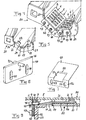
- a sliding element 1 according to an embodiment of the present invention is illustrated in Figs 1-3 .
- This sliding element 1 is intended to be arranged between two mutually displaceable telescopic parts of a telescopic device and comprises a plate-shaped body 2, which is made of a material with low coefficient of friction, such as for instance a suitable plastic material or a suitable metallic or ceramic material. Suitable materials may for instance be Robalon-Z, POLYform (POM), brass, ceramics or the similar.
- the body 2 may be rectangular as seen in a planar view, as shown in Fig 1 , or have any other suitable shape as seen in a planar view, for instance circular or elliptical.
- the plate-shaped body 2 of the sliding element has an underside 3, through which the sliding element 1 is intended to rest against a support surface of a first telescopic part to which the sliding element is mounted, and an opposite upper side 4, which constitutes a sliding surface and through which the sliding element 1 is intended to be in sliding contact with the surface of a second telescopic part.
- a number of elongated lubricant grooves 5, 6 for receiving lubricant, for instance in the form of oil, are arranged in the upper side 4 of the body. These lubricant grooves 5, 6 are formed as depressions in the upper side 4.
- the respective lubricant groove 5, 6 is consequently open at the top and is provided with a bottom surface 13, which is lowered from the upper side 4 and which closes the lubricant groove at the bottom.
- the respective lubricant groove 5, 6 does not extend all the way to the edges of the body, and the lubricant can thereby be retained in the lubricant groove.
- the sliding element 1 is in its upper side 4 provided with four shorter lubricant grooves 6 and one longer lubricant groove 5.
- the longer lubricant groove 5 comprises a central section 5a extending rectilinearly along the longitudinal axis of the sliding element, and three transverse sections 5b extending perpendicularly to the central section 5a.
- the transverse sections 5b cross the central section 5a and are connected to the central section so that lubricant received in the central section 5a can flow from the central section further on to the transverse sections 5b.
- the last-mentioned lubricant groove 5 is connected to a feeding channel 7 extending inside the sliding element 1, which feeding channel has an inlet opening 8 arranged in an external edge surface 9 of the sliding element. Through the inlet opening 8 and the feeding channel 7, lubricant can be fed into this lubricant groove 5.
- the inlet channel 7 runs into a deepened part of the central section 5a of the lubricant groove, as shown in Fig 3 .
- the feeding channel 7 is formed by a hole that extends through a part of the sliding element.
- the feeding channel 7 suitably extends in parallel or at least essentially in parallel with the upper side 4 of the body.
- a projection 10 is arranged on the underside 3 of the body. This projection 10 projects downwards from the underside 3 of the body.
- the projection 10 extends to the edge surface 9 of the sliding element that is provided with the inlet opening 8, and the feeding channel 7 of the sliding element is arranged in this projection.
- the projection 10 has a width that is smaller than the width of the body 2 of the sliding element and a length that is smaller than the length of said body.
- the lateral edges of the projection extend perpendicularly to the underside 3 of the body, and the projection 10 has a rectangular cross-sectional shape in this case.
- the projection 10 also has a rectangular shape as seen in a planar view.
- the projection 10 and the plate-shaped body 2 are suitably made in one piece, for instance by injection moulding.
- Fig 4 shows two sliding elements 1 of the type described above mounted to an end of a telescopic part 20, which in the following is denominated first telescopic part.
- the sliding elements 1 are attached to a wall 21 of the first telescopic part 20 and this first telescopic part is intended to be in sliding contact with a second telescopic part 30 (see Fig 8 ) through these sliding elements.
- the projection 10 of the respective sliding element 1 is designed for insertion into a recess 22 (see Fig 5 ), which is arranged in the wall 21 of the first telescopic part 20.
- the respective recess 22 is consequently designed to receive the projection 10 of a sliding element and has a shape essentially corresponding to the shape of the projection of the sliding element to thereby limit the displaceability of the sliding element in a plane parallel to the wall 21 when the projection 10 is received in the recess 22. Consequently, the projection 10 acts as a stop lug which contributes to keep the sliding element in place to the wall 21.
- the respective recess 22 has a rectangular shape corresponding to the rectangular shape of the projection 10 of the sliding element.
- the body 2 When the projection 10 is inserted into the associated recess 22, the body 2 rests, through the surface of the underside 3 surrounding the projection 10, against the surface of the wall 21 that surrounds the recess 22, whereas lateral edges of the projection abut against the edges of the recess.
- the sliding element 1 may either rest directly against the wall 21 or rest against the wall through a spacer plate 50, as will be more closely described below with reference to Figs 7 and 8 .
- a holding element 40 is attached to a flange 23, which is arranged at the end of the first telescopic part 20.
- a pin 41 is in its turn fixed to the holding element 40.
- This pin 41 is hollow and open at its ends so that a flow-through channel for lubricant is formed inside the pin.
- the pin 41 projects from the holding element 40 and is insertable into the feeding channel 7 of the sliding element through the inlet opening 8 of the feeding channel, as illustrated in Fig 8 .
- An inlet nozzle 42 with a non-return valve 45 is also fixed to the holding element 40 and connected to the pin 41 in order to allow feeding of lubricant to the pin through the inlet nozzle.
- the inlet nozzle 42 may be screwed directly onto the pin 41 through an internal thread at the end of the pin that faces the holding element 40 and a corresponding external thread on the inlet nozzle.
- the pin 41 extends into the feeding channel 7 of the sliding element and by connecting a lubricant receptacle to the inlet nozzle 42, for instance through a hose or the similar, lubricant can be introduced into the lubricant groove 5 through the inlet nozzle 42, the pin 41 and the feeding channel 7.
- the pin 41 is suitably designed to keep the sliding element 1 secured to the first telescopic part 20 through engagement in the feeding channel 7, with the pin preventing a displacement of the sliding element away from the wall 21 in a direction perpendicular to the wall.
- the holding element 40 may with advantage have the shape of a plate and be attachable to said flange 23 by means of screw joint, as illustrated in Figs 4 and 8 .
- the holding element 40 is attached to the flange 23 by means of two screws 43, which extend through a respective through recess 44 in the holding element and are screwed into a respective threaded hole 24 in the flange 23.
- These recesses 44 suitably have an elongated shape as seen in a direction perpendicular to the wall 21, as illustrated in Fig 6 , so as to thereby make possible an adjustment of the position of the holding element in relation to the flange 23 in the last mentioned direction.
- the projection 10 has a height h (see Fig 3 ) from the underside 3 of the body that is smaller than or equal to the thickness of the wall 21. Furthermore, the recess 22 is open towards the end of the wall.
- the holding element 40 is designed to abut, when attached to said flange 23, against an external edge surface 9 of the sliding element 1 to thereby prevent the projection 10 from being displaced in a plane parallel to the wall 21 out of the recess 22.
- the last-mentioned edge surface 9 and the edge surface that is provided with the inlet opening 8 of the feeding channel are suitably one and the same edge surface of the sliding element.
- the edge surface 9 suitably extends perpendicularly to the upper side 4 and the underside 3 of the body 2 of the sliding element, as illustrated in Figs 1-3 .
- the edge surface 9 is suitably retracted in relation to the adjacent external edge surface 11 of the body 2 of the sliding element so that a shoulder 12 is formed between these edge surfaces 9, 11.
- the upper edge 46 of the holding element is intended to abut against this shoulder 12 of the sliding element.
- the sliding element 1 When the sliding element 1 is to be attached to the first telescopic part 20, the sliding element is applied with the underside 3 of the body 2 against the wall 21 of the telescopic part and with the projection 10 inserted into an associated recess 22 in the wall. Thereafter, the holding element 40 is moved towards the edge surface 9 of the sliding element so that the pin 41 that projects from the holding element is pushed into the feeding channel 7 of the sliding element through the inlet opening 8. The holding element 40 is then secured to the flange 23 by screwing, whereby the sliding element 1 is secured to the wall 21 under the effect of the holding element 40 and the pin 41.
- the holding element 40 and the edges of the recess 22 will prevent a displacement of the sliding element 1 in relation to the first telescopic part 20 in a plane parallel to the wall 21, at the same time as the pin 41 prevents a displacement of the sliding element 1 away from the wall 21 in a direction perpendicular to the wall.
- the upper side 4 of the body is intended to be in sliding contact with a surface 31 of a second telescopic part 30 so as to thereby form a sliding surface between this second telescopic part 30 and the first telescopic part 20.
- These two telescopic parts 20, 30 are arranged to be displaceable in relation to each other in a plane extending in parallel with the upper side 4 of the body and they may be arranged to rest against each other through the sliding element 1.
- a sliding element 1 is shown mounted to a first telescopic part 20 in the above-described manner and with a second telescopic part 30 in sliding contact with the upper side 4 of the body 2 of the sliding element.
- lubricant can be introduced into the lubricant groove 5 through the inlet nozzle 42, the pin 41 and the feeding channel 7 while the second telescopic part 30 remains in contact with the upper side 4 of the body, i.e. without requiring any separation of the two telescopic parts 20, 30 from each other.
- a spacer plate 50 is placed between the underside 3 of the body 2 of the sliding element and the wall 21.
- This spacer plate 50 is illustrated in Fig 7 and is provided with an opening 51 designed to receive the projection 10 of the sliding element.
- This opening 51 has a shape corresponding to the shape of the recess 22 in the wall 21 and is intended to be located above this recess 22 when the spacer plate 50 is in place between the sliding element 1 and the wall 21.
- the spacer plate 50 is provided with a downwardly projecting mounting flange 52, which is intended to be clamped between the holding element 40 and the flange 23 of the first telescopic part when the holding element is secured by screwing to the last-mentioned flange 23.
- Recesses 53 for receiving the screws 43 are arranged in the mounting flange 52.
- the recesses 53 of the mounting flange are intended to be aligned with the recesses 44 of the holding element 40 and suitably has the same shape as these.
- the spacer plate is provided with a downward projecting support lug 54, which has the same thickness as the mounting flange 52 and is intended to abut against the inner edge of the recess 22 in the wall 21.
- the spacer plate 50 is with advantage made my punching and bending of a piece of plate.
- a sliding element 1 of the type in question is with advantage used in a telescopic device in the form of a telescopic crane boom or a telescopic support leg, in which case the sliding element is installed between two telescopic crane boom parts or between two telescopic support leg parts.
Landscapes
- Engineering & Computer Science (AREA)
- General Engineering & Computer Science (AREA)
- Mechanical Engineering (AREA)
- Chemical & Material Sciences (AREA)
- Oil, Petroleum & Natural Gas (AREA)
- Jib Cranes (AREA)
- Mutual Connection Of Rods And Tubes (AREA)
Claims (11)
- Dispositif télescopique, en particulier sous la forme d'une flèche de grue télescopique ou d'une jambe de support télescopique, comprenant au moins une première partie (20) télescopique et une deuxième partie (30) télescopique, qui sont déplaçables mutuellement, et un élément (1) coulissant, qui est destiné à être disposé entre ces parties télescopiques et par lequel la première partie (20) télescopique est destinée à être en contact coulissant avec la deuxième partie (30) télescopique, l'élément (1) coulissant pouvant être fixé à une paroi (21) de la première partie (20) télescopique et comprenant un corps (2) en forme de plaque, ayant :- un côté (3) inférieur, par lequel l'élément coulissant est destiné à reposer sur une surface de support de la première partie (20) télescopique ;- un côté (4) supérieur, qui constitue une surface de coulissement et par lequel l'élément coulissant est destiné à être en contact coulissant avec une surface de la deuxième partie (30) télescopique ; et- une ou plusieurs rainures (5, 6) pour du lubrifiant ménagées dans le côté (4) supérieur pour recevoir du lubrifiant,caractérisé en :- ce qu'au moins l'une des rainures (5) pour du lubrifiant communique avec un canal (7) d'alimentation s'étendant à l'intérieur de l'élément (1) coulissant, ce canal d'alimentation ayant une ouverture (8) d'entrée ménagée dans une surface (9) de bord extérieur de l'élément coulissant afin de permettre d'alimenter en lubrifiant cette rainure (5) pour du lubrifiant par l'intermédiaire de l'ouverture (8) d'entrée et du canal (7) d'alimentation ;- ce que le dispositif télescopique comprend un élément (40) de maintien et une broche (41) fixée à l'élément de maintien et en faisant saillie, broche qui peut être insérée dans le canal (7) d'alimentation de l'élément coulissant par l'ouverture (8) d'entrée du canal d'alimentation ;- ce que l'élément (40) de maintien est conçu pour être fixé à un rebord (23) de la première partie (20) télescopique, alors que la broche (41) est reçue dans le canal (7) d'alimentation de l'élément coulissant ; et- ce que la broche (41) est creuse afin de permettre d'alimenter en lubrifiant le canal (7) d'alimentation de l'élément coulissant par l'intermédiaire de la broche.
- Dispositif télescopique suivant la revendication 1, caractérisé en ce que le canal (7) d'alimentation s'étend à l'intérieur de l'élément coulissant parallèlement ou au moins sensiblement parallèlement au côté (4) supérieur du corps.
- Dispositif télescopique suivant la revendication 1 ou 2, caractérisé en :- ce qu'une saillie (10) est ménagée sur le côté (3) inférieur du corps (2) de l'élément coulissant, cette saillie (10) s'étendant vers la surface (9) de bord, qui est munie de l'ouverture (8) d'entrée ;- ce que le canal (7) d'alimentation de l'élément coulissant ou au moins une partie de ce canal d'alimentation est ménagé dans cette saillie (10 ; et- ce que la paroi (21) de la première partie (20) télescopique est pourvue d'un chambrage (22), qui est conçu pour recevoir la saillie (10) de l'élément (1) coulissant.
- Dispositif télescopique suivant la revendication 3, caractérisé en ce que le chambrage (22) dans la paroi (21) a une forme correspondant sensiblement à la forme de la saillie (10) de l'élément coulissant pour limiter ainsi la possibilité de se déplacer de l'élément coulissant dans un plan parallèle à cette paroi (21), lorsque la saillie (10) est reçue dans le chambrage (22).
- Dispositif télescopique suivant la revendication 3 ou 4, caractérisé en ce que le dispositif télescopique comprend une plaque (50) formant entretoise, qui, au moyen de l'élément (40) de maintien, peut être fixée à la paroi (21) de la première partie (20) télescopique entre la paroi (21) et l'élément (1) coulissant et qui est pourvue d'une ouverture (51) conçue pour recevoir la saillie (10) de l'élément coulissant.
- Dispositif télescopique suivant l'une quelconque des revendications 1 à 5, caractérisé en ce qu'une buse (42) d'entrée ayant un clapet antiretour (45) est fixée à l'élément (40) de maintien et communique avec la broche (41) afin de permettre d'alimenter la broche en lubrifiant par l'intermédiaire de cette buse d'entrée.
- Dispositif télescopique suivant l'une quelconque des revendications 1 à 6, caractérisé en ce que la broche (41) est conçue pour maintenir l'élément (1) coulissant fixé à la première partie (20) télescopique par pénétration dans le canal (7) d'alimentation.
- Dispositif télescopique suivant l'une quelconque des revendications 1 à 7, caractérisé en ce que l'élément (40) de maintien est conçu pour buter, lorsqu'il est fixé au rebord (23), sur une surface (9) de bord extérieur de l'élément coulissant en limitant ainsi la possibilité de se déplacer de l'élément coulissant dans un plan parallèle à la paroi (21).
- Dispositif télescopique suivant la revendication 8, caractérisé en ce que l'élément (40) de maintien est conçu pour buter, lorsqu'il est fixé au rebord (23), sur une surface (9) de bord extérieur, dans laquelle l'ouverture (8) d'entrée du canal d'alimentation est ménagée.
- Dispositif télescopique suivant l'une quelconque des revendications 1 à 9, caractérisé en ce que l'élément (40) de maintien est conçu pour être fixé au rebord (23) au moyen d'un assemblage à vis.
- Dispositif télescopique suivant l'une quelconque des revendications 1 à 10, caractérisé en ce que l'élément (40) de maintien a la forme d'une plaque.
Applications Claiming Priority (2)
| Application Number | Priority Date | Filing Date | Title |
|---|---|---|---|
| SE0950916A SE534416C2 (sv) | 2009-11-30 | 2009-11-30 | Teleskopisk anordning innefattande ett glidelement |
| PCT/SE2010/051283 WO2011065899A1 (fr) | 2009-11-30 | 2010-11-22 | Élément coulissant et dispositif télescopique comportant un tel élément coulissant |
Publications (3)
| Publication Number | Publication Date |
|---|---|
| EP2464591A1 EP2464591A1 (fr) | 2012-06-20 |
| EP2464591A4 EP2464591A4 (fr) | 2013-08-07 |
| EP2464591B1 true EP2464591B1 (fr) | 2014-11-12 |
Family
ID=44066784
Family Applications (1)
| Application Number | Title | Priority Date | Filing Date |
|---|---|---|---|
| EP10833664.5A Not-in-force EP2464591B1 (fr) | 2009-11-30 | 2010-11-22 | Élément coulissant et dispositif télescopique comportant un tel élément coulissant |
Country Status (3)
| Country | Link |
|---|---|
| EP (1) | EP2464591B1 (fr) |
| SE (1) | SE534416C2 (fr) |
| WO (1) | WO2011065899A1 (fr) |
Families Citing this family (4)
| Publication number | Priority date | Publication date | Assignee | Title |
|---|---|---|---|---|
| JP6121799B2 (ja) * | 2013-05-29 | 2017-04-26 | 株式会社タダノ | 伸縮ブームのスライド装置 |
| CN105805156A (zh) * | 2016-03-24 | 2016-07-27 | 上海交通大学 | 一种tbm主梁鞍架连接导轨槽 |
| IT201800004277A1 (it) * | 2018-04-06 | 2019-10-06 | Braccio telescopico per una gru di sollevamento di carichi | |
| JP7375484B2 (ja) * | 2019-11-15 | 2023-11-08 | 株式会社タダノ | ブームの制振装置 |
Family Cites Families (11)
| Publication number | Priority date | Publication date | Assignee | Title |
|---|---|---|---|---|
| US3796016A (en) * | 1971-11-26 | 1974-03-12 | Cascade Corp | Extensible material handling boom |
| US3837502A (en) * | 1973-03-12 | 1974-09-24 | Bucyrus Erie Co | Light weight boom construction |
| JPS5441503Y2 (fr) * | 1975-07-28 | 1979-12-04 | ||
| JPS5872252U (ja) * | 1981-11-07 | 1983-05-16 | 株式会社クボタ | シヨベル作業用ア−ム |
| FR2531691B1 (fr) * | 1982-08-10 | 1986-03-28 | Ppm Sa | Fleche telescopique a dispositifs d'appui et/ou de guidage de ses troncons perfectionnes |
| JPS60133892U (ja) * | 1984-02-14 | 1985-09-06 | 極東開発工業株式会社 | 伸縮ブ−ムにおけるスライドシユ−取付構造 |
| DE29804237U1 (de) * | 1998-03-10 | 1998-05-07 | Liebherr-Werk Ehingen Gmbh, 89584 Ehingen | Gleitlager für ineinandergelagerte schalenförmige Körper |
| CN2356210Y (zh) * | 1998-12-25 | 1999-12-29 | 向昌明 | 直通式黄油嘴 |
| DE10164565C2 (de) * | 2001-12-14 | 2003-12-11 | Terex Demag Gmbh & Co Kg | Teleskopausleger mit Schmiermittelzuführung |
| DE102006023963B4 (de) * | 2006-05-22 | 2008-04-17 | PAN-Metallgesellschaft Baumgärtner GmbH & Co KG | Gleitelement und Verfahren zu dessen Herstellung |
| CN201358141Y (zh) * | 2009-03-13 | 2009-12-09 | 徐州重型机械有限公司 | 滑块装置及具有该滑块装置的起重机 |
-
2009
- 2009-11-30 SE SE0950916A patent/SE534416C2/sv not_active IP Right Cessation
-
2010
- 2010-11-22 WO PCT/SE2010/051283 patent/WO2011065899A1/fr not_active Ceased
- 2010-11-22 EP EP10833664.5A patent/EP2464591B1/fr not_active Not-in-force
Also Published As
| Publication number | Publication date |
|---|---|
| WO2011065899A1 (fr) | 2011-06-03 |
| SE0950916A1 (sv) | 2011-05-31 |
| EP2464591A4 (fr) | 2013-08-07 |
| EP2464591A1 (fr) | 2012-06-20 |
| SE534416C2 (sv) | 2011-08-16 |
Similar Documents
| Publication | Publication Date | Title |
|---|---|---|
| EP2464592B1 (fr) | Dispositif télescopique comportant un élément coulissant | |
| US9808083B2 (en) | Device for releasably connecting a furniture drawer to a guidance unit that moveably guides the drawer in a furniture body | |
| EP2047155B1 (fr) | Système soupape | |
| DE102008014382B3 (de) | Leitungsauslass | |
| WO2008155117A1 (fr) | Distributeur, notamment distributeur de colle | |
| DE102013105544A1 (de) | Wasserablaufvorrichtung für eine sanitäre Anlage, wie einen bodenebenen Duschplatz | |
| EP2464591A1 (fr) | Élément coulissant et dispositif télescopique comportant un tel élément coulissant | |
| EP1450995B1 (fr) | Auxiliaire de positionnement | |
| DE102007003821A1 (de) | Transistorklemmvorrichtung | |
| EP2390430B1 (fr) | Dispositif de fixation en particulier pour des appareils sanitaires muraux | |
| DE10147023B4 (de) | Befestigungsvorrichtung für Sensoren und Sensor | |
| DE20307903U1 (de) | Seilaufhängung für Leuchten | |
| DE102015113737B3 (de) | Sensor | |
| DE19624382C1 (de) | Klemmvorrichtung | |
| EP2965656B1 (fr) | Dispositif de montage pour un élément support sur une colonne porteuse | |
| EP2181956B1 (fr) | Élément coulissant et dispositif télescopique avec tel élément coulissant | |
| DE102011006375A1 (de) | Zylinderschaltung | |
| DE102013222952B4 (de) | Spannmodul eines Spannsystems, insbesondere eines Nullpunktsystems, mit elastischer Auflagefläche | |
| DE202015104390U1 (de) | Sensor | |
| AT509757B1 (de) | Vorrichtung zum haltern eines plattenheizkörpers | |
| WO2009103328A1 (fr) | Support de câble ou de tuyau pouvant être fixé sur une paroi mince par un dispositif d’accrochage élastique | |
| EP2251947B1 (fr) | Canal systémique pour une alimentation de milieux et poste de travail doté d'un canal systémique | |
| EP2913535B1 (fr) | Support d'antennes | |
| DE10154967A1 (de) | Klemmvorrichtung zur Befestigung von Bauelementen an mit einer T-Nut versehenen Halteelementen | |
| EP3312130B1 (fr) | Élément coulissant et dispositif télescopique comprenant un tel élément coulissant |
Legal Events
| Date | Code | Title | Description |
|---|---|---|---|
| PUAI | Public reference made under article 153(3) epc to a published international application that has entered the european phase |
Free format text: ORIGINAL CODE: 0009012 |
|
| 17P | Request for examination filed |
Effective date: 20120214 |
|
| AK | Designated contracting states |
Kind code of ref document: A1 Designated state(s): AL AT BE BG CH CY CZ DE DK EE ES FI FR GB GR HR HU IE IS IT LI LT LU LV MC MK MT NL NO PL PT RO RS SE SI SK SM TR |
|
| DAX | Request for extension of the european patent (deleted) | ||
| A4 | Supplementary search report drawn up and despatched |
Effective date: 20130705 |
|
| RIC1 | Information provided on ipc code assigned before grant |
Ipc: B66C 23/697 20060101AFI20130701BHEP Ipc: F16C 33/10 20060101ALI20130701BHEP Ipc: F16C 35/02 20060101ALI20130701BHEP Ipc: F16C 29/02 20060101ALI20130701BHEP |
|
| REG | Reference to a national code |
Ref country code: DE Ref legal event code: R079 Ref document number: 602010020280 Country of ref document: DE Free format text: PREVIOUS MAIN CLASS: B66C0023697000 Ipc: B66C0023700000 |
|
| RIC1 | Information provided on ipc code assigned before grant |
Ipc: F16C 35/02 20060101ALI20140318BHEP Ipc: B66C 23/70 20060101ALI20140318BHEP Ipc: F16C 33/10 20060101ALI20140318BHEP Ipc: B66C 23/697 20060101AFI20140318BHEP Ipc: F16C 29/02 20060101ALI20140318BHEP |
|
| RIC1 | Information provided on ipc code assigned before grant |
Ipc: B66C 23/70 20060101AFI20140409BHEP |
|
| GRAP | Despatch of communication of intention to grant a patent |
Free format text: ORIGINAL CODE: EPIDOSNIGR1 |
|
| INTG | Intention to grant announced |
Effective date: 20140619 |
|
| GRAS | Grant fee paid |
Free format text: ORIGINAL CODE: EPIDOSNIGR3 |
|
| GRAA | (expected) grant |
Free format text: ORIGINAL CODE: 0009210 |
|
| AK | Designated contracting states |
Kind code of ref document: B1 Designated state(s): AL AT BE BG CH CY CZ DE DK EE ES FI FR GB GR HR HU IE IS IT LI LT LU LV MC MK MT NL NO PL PT RO RS SE SI SK SM TR |
|
| REG | Reference to a national code |
Ref country code: GB Ref legal event code: FG4D |
|
| REG | Reference to a national code |
Ref country code: CH Ref legal event code: EP |
|
| REG | Reference to a national code |
Ref country code: AT Ref legal event code: REF Ref document number: 695600 Country of ref document: AT Kind code of ref document: T Effective date: 20141115 |
|
| REG | Reference to a national code |
Ref country code: IE Ref legal event code: FG4D |
|
| REG | Reference to a national code |
Ref country code: DE Ref legal event code: R096 Ref document number: 602010020280 Country of ref document: DE Effective date: 20141224 |
|
| REG | Reference to a national code |
Ref country code: NL Ref legal event code: VDEP Effective date: 20141112 |
|
| REG | Reference to a national code |
Ref country code: AT Ref legal event code: MK05 Ref document number: 695600 Country of ref document: AT Kind code of ref document: T Effective date: 20141112 |
|
| PG25 | Lapsed in a contracting state [announced via postgrant information from national office to epo] |
Ref country code: FI Free format text: LAPSE BECAUSE OF FAILURE TO SUBMIT A TRANSLATION OF THE DESCRIPTION OR TO PAY THE FEE WITHIN THE PRESCRIBED TIME-LIMIT Effective date: 20141112 Ref country code: NL Free format text: LAPSE BECAUSE OF FAILURE TO SUBMIT A TRANSLATION OF THE DESCRIPTION OR TO PAY THE FEE WITHIN THE PRESCRIBED TIME-LIMIT Effective date: 20141112 Ref country code: NO Free format text: LAPSE BECAUSE OF FAILURE TO SUBMIT A TRANSLATION OF THE DESCRIPTION OR TO PAY THE FEE WITHIN THE PRESCRIBED TIME-LIMIT Effective date: 20150212 Ref country code: PT Free format text: LAPSE BECAUSE OF FAILURE TO SUBMIT A TRANSLATION OF THE DESCRIPTION OR TO PAY THE FEE WITHIN THE PRESCRIBED TIME-LIMIT Effective date: 20150312 Ref country code: IS Free format text: LAPSE BECAUSE OF FAILURE TO SUBMIT A TRANSLATION OF THE DESCRIPTION OR TO PAY THE FEE WITHIN THE PRESCRIBED TIME-LIMIT Effective date: 20150312 Ref country code: LT Free format text: LAPSE BECAUSE OF FAILURE TO SUBMIT A TRANSLATION OF THE DESCRIPTION OR TO PAY THE FEE WITHIN THE PRESCRIBED TIME-LIMIT Effective date: 20141112 Ref country code: ES Free format text: LAPSE BECAUSE OF FAILURE TO SUBMIT A TRANSLATION OF THE DESCRIPTION OR TO PAY THE FEE WITHIN THE PRESCRIBED TIME-LIMIT Effective date: 20141112 |
|
| PG25 | Lapsed in a contracting state [announced via postgrant information from national office to epo] |
Ref country code: RS Free format text: LAPSE BECAUSE OF FAILURE TO SUBMIT A TRANSLATION OF THE DESCRIPTION OR TO PAY THE FEE WITHIN THE PRESCRIBED TIME-LIMIT Effective date: 20141112 Ref country code: GR Free format text: LAPSE BECAUSE OF FAILURE TO SUBMIT A TRANSLATION OF THE DESCRIPTION OR TO PAY THE FEE WITHIN THE PRESCRIBED TIME-LIMIT Effective date: 20150213 Ref country code: SE Free format text: LAPSE BECAUSE OF FAILURE TO SUBMIT A TRANSLATION OF THE DESCRIPTION OR TO PAY THE FEE WITHIN THE PRESCRIBED TIME-LIMIT Effective date: 20141112 Ref country code: CY Free format text: LAPSE BECAUSE OF FAILURE TO SUBMIT A TRANSLATION OF THE DESCRIPTION OR TO PAY THE FEE WITHIN THE PRESCRIBED TIME-LIMIT Effective date: 20141112 Ref country code: PL Free format text: LAPSE BECAUSE OF FAILURE TO SUBMIT A TRANSLATION OF THE DESCRIPTION OR TO PAY THE FEE WITHIN THE PRESCRIBED TIME-LIMIT Effective date: 20141112 Ref country code: HR Free format text: LAPSE BECAUSE OF FAILURE TO SUBMIT A TRANSLATION OF THE DESCRIPTION OR TO PAY THE FEE WITHIN THE PRESCRIBED TIME-LIMIT Effective date: 20141112 Ref country code: AT Free format text: LAPSE BECAUSE OF FAILURE TO SUBMIT A TRANSLATION OF THE DESCRIPTION OR TO PAY THE FEE WITHIN THE PRESCRIBED TIME-LIMIT Effective date: 20141112 Ref country code: LV Free format text: LAPSE BECAUSE OF FAILURE TO SUBMIT A TRANSLATION OF THE DESCRIPTION OR TO PAY THE FEE WITHIN THE PRESCRIBED TIME-LIMIT Effective date: 20141112 |
|
| PG25 | Lapsed in a contracting state [announced via postgrant information from national office to epo] |
Ref country code: BE Free format text: LAPSE BECAUSE OF NON-PAYMENT OF DUE FEES Effective date: 20141130 |
|
| REG | Reference to a national code |
Ref country code: CH Ref legal event code: PL |
|
| PG25 | Lapsed in a contracting state [announced via postgrant information from national office to epo] |
Ref country code: LI Free format text: LAPSE BECAUSE OF NON-PAYMENT OF DUE FEES Effective date: 20141130 Ref country code: EE Free format text: LAPSE BECAUSE OF FAILURE TO SUBMIT A TRANSLATION OF THE DESCRIPTION OR TO PAY THE FEE WITHIN THE PRESCRIBED TIME-LIMIT Effective date: 20141112 Ref country code: SK Free format text: LAPSE BECAUSE OF FAILURE TO SUBMIT A TRANSLATION OF THE DESCRIPTION OR TO PAY THE FEE WITHIN THE PRESCRIBED TIME-LIMIT Effective date: 20141112 Ref country code: CH Free format text: LAPSE BECAUSE OF NON-PAYMENT OF DUE FEES Effective date: 20141130 Ref country code: DK Free format text: LAPSE BECAUSE OF FAILURE TO SUBMIT A TRANSLATION OF THE DESCRIPTION OR TO PAY THE FEE WITHIN THE PRESCRIBED TIME-LIMIT Effective date: 20141112 Ref country code: RO Free format text: LAPSE BECAUSE OF FAILURE TO SUBMIT A TRANSLATION OF THE DESCRIPTION OR TO PAY THE FEE WITHIN THE PRESCRIBED TIME-LIMIT Effective date: 20141112 Ref country code: CZ Free format text: LAPSE BECAUSE OF FAILURE TO SUBMIT A TRANSLATION OF THE DESCRIPTION OR TO PAY THE FEE WITHIN THE PRESCRIBED TIME-LIMIT Effective date: 20141112 |
|
| REG | Reference to a national code |
Ref country code: DE Ref legal event code: R097 Ref document number: 602010020280 Country of ref document: DE |
|
| REG | Reference to a national code |
Ref country code: IE Ref legal event code: MM4A |
|
| PG25 | Lapsed in a contracting state [announced via postgrant information from national office to epo] |
Ref country code: MC Free format text: LAPSE BECAUSE OF FAILURE TO SUBMIT A TRANSLATION OF THE DESCRIPTION OR TO PAY THE FEE WITHIN THE PRESCRIBED TIME-LIMIT Effective date: 20141112 |
|
| PLBE | No opposition filed within time limit |
Free format text: ORIGINAL CODE: 0009261 |
|
| STAA | Information on the status of an ep patent application or granted ep patent |
Free format text: STATUS: NO OPPOSITION FILED WITHIN TIME LIMIT |
|
| 26N | No opposition filed |
Effective date: 20150813 |
|
| PG25 | Lapsed in a contracting state [announced via postgrant information from national office to epo] |
Ref country code: IE Free format text: LAPSE BECAUSE OF NON-PAYMENT OF DUE FEES Effective date: 20141122 |
|
| REG | Reference to a national code |
Ref country code: FR Ref legal event code: PLFP Year of fee payment: 6 |
|
| PG25 | Lapsed in a contracting state [announced via postgrant information from national office to epo] |
Ref country code: IT Free format text: LAPSE BECAUSE OF FAILURE TO SUBMIT A TRANSLATION OF THE DESCRIPTION OR TO PAY THE FEE WITHIN THE PRESCRIBED TIME-LIMIT Effective date: 20141112 |
|
| PGFP | Annual fee paid to national office [announced via postgrant information from national office to epo] |
Ref country code: GB Payment date: 20151123 Year of fee payment: 6 |
|
| PG25 | Lapsed in a contracting state [announced via postgrant information from national office to epo] |
Ref country code: SI Free format text: LAPSE BECAUSE OF FAILURE TO SUBMIT A TRANSLATION OF THE DESCRIPTION OR TO PAY THE FEE WITHIN THE PRESCRIBED TIME-LIMIT Effective date: 20141112 |
|
| PG25 | Lapsed in a contracting state [announced via postgrant information from national office to epo] |
Ref country code: SM Free format text: LAPSE BECAUSE OF FAILURE TO SUBMIT A TRANSLATION OF THE DESCRIPTION OR TO PAY THE FEE WITHIN THE PRESCRIBED TIME-LIMIT Effective date: 20141112 |
|
| PG25 | Lapsed in a contracting state [announced via postgrant information from national office to epo] |
Ref country code: BG Free format text: LAPSE BECAUSE OF FAILURE TO SUBMIT A TRANSLATION OF THE DESCRIPTION OR TO PAY THE FEE WITHIN THE PRESCRIBED TIME-LIMIT Effective date: 20141112 |
|
| PG25 | Lapsed in a contracting state [announced via postgrant information from national office to epo] |
Ref country code: LU Free format text: LAPSE BECAUSE OF NON-PAYMENT OF DUE FEES Effective date: 20141122 Ref country code: MT Free format text: LAPSE BECAUSE OF FAILURE TO SUBMIT A TRANSLATION OF THE DESCRIPTION OR TO PAY THE FEE WITHIN THE PRESCRIBED TIME-LIMIT Effective date: 20141112 Ref country code: TR Free format text: LAPSE BECAUSE OF FAILURE TO SUBMIT A TRANSLATION OF THE DESCRIPTION OR TO PAY THE FEE WITHIN THE PRESCRIBED TIME-LIMIT Effective date: 20141112 Ref country code: HU Free format text: LAPSE BECAUSE OF FAILURE TO SUBMIT A TRANSLATION OF THE DESCRIPTION OR TO PAY THE FEE WITHIN THE PRESCRIBED TIME-LIMIT; INVALID AB INITIO Effective date: 20101122 |
|
| REG | Reference to a national code |
Ref country code: FR Ref legal event code: PLFP Year of fee payment: 7 |
|
| PGFP | Annual fee paid to national office [announced via postgrant information from national office to epo] |
Ref country code: FR Payment date: 20161116 Year of fee payment: 7 |
|
| GBPC | Gb: european patent ceased through non-payment of renewal fee |
Effective date: 20161122 |
|
| PG25 | Lapsed in a contracting state [announced via postgrant information from national office to epo] |
Ref country code: GB Free format text: LAPSE BECAUSE OF NON-PAYMENT OF DUE FEES Effective date: 20161122 |
|
| PG25 | Lapsed in a contracting state [announced via postgrant information from national office to epo] |
Ref country code: MK Free format text: LAPSE BECAUSE OF FAILURE TO SUBMIT A TRANSLATION OF THE DESCRIPTION OR TO PAY THE FEE WITHIN THE PRESCRIBED TIME-LIMIT Effective date: 20141112 |
|
| REG | Reference to a national code |
Ref country code: FR Ref legal event code: ST Effective date: 20180731 |
|
| PG25 | Lapsed in a contracting state [announced via postgrant information from national office to epo] |
Ref country code: AL Free format text: LAPSE BECAUSE OF FAILURE TO SUBMIT A TRANSLATION OF THE DESCRIPTION OR TO PAY THE FEE WITHIN THE PRESCRIBED TIME-LIMIT Effective date: 20141112 Ref country code: FR Free format text: LAPSE BECAUSE OF NON-PAYMENT OF DUE FEES Effective date: 20171130 |
|
| REG | Reference to a national code |
Ref country code: DE Ref legal event code: R082 Ref document number: 602010020280 Country of ref document: DE Representative=s name: MANITZ FINSTERWALD PATENT- UND RECHTSANWALTSPA, DE Ref country code: DE Ref legal event code: R081 Ref document number: 602010020280 Country of ref document: DE Owner name: HIAB AB, SE Free format text: FORMER OWNER: CARGOTEC PATENTER AB, LJUNGBY, SE |
|
| PGFP | Annual fee paid to national office [announced via postgrant information from national office to epo] |
Ref country code: DE Payment date: 20231127 Year of fee payment: 14 |
|
| REG | Reference to a national code |
Ref country code: DE Ref legal event code: R119 Ref document number: 602010020280 Country of ref document: DE |
|
| PG25 | Lapsed in a contracting state [announced via postgrant information from national office to epo] |
Ref country code: DE Free format text: LAPSE BECAUSE OF NON-PAYMENT OF DUE FEES Effective date: 20250603 |