EP2463045B1 - Gleitventilvorrichtung zur automatischen oberflächendruckbeaufschlagung sowie oberflächendruckbeaufschlagungsverfahren - Google Patents
Gleitventilvorrichtung zur automatischen oberflächendruckbeaufschlagung sowie oberflächendruckbeaufschlagungsverfahren Download PDFInfo
- Publication number
- EP2463045B1 EP2463045B1 EP10839147.5A EP10839147A EP2463045B1 EP 2463045 B1 EP2463045 B1 EP 2463045B1 EP 10839147 A EP10839147 A EP 10839147A EP 2463045 B1 EP2463045 B1 EP 2463045B1
- Authority
- EP
- European Patent Office
- Prior art keywords
- case
- slide
- surface pressure
- seal
- seal case
- Prior art date
- Legal status (The legal status is an assumption and is not a legal conclusion. Google has not performed a legal analysis and makes no representation as to the accuracy of the status listed.)
- Not-in-force
Links
Images


Classifications
-
- B—PERFORMING OPERATIONS; TRANSPORTING
- B22—CASTING; POWDER METALLURGY
- B22D—CASTING OF METALS; CASTING OF OTHER SUBSTANCES BY THE SAME PROCESSES OR DEVICES
- B22D41/00—Casting melt-holding vessels, e.g. ladles, tundishes, cups or the like
- B22D41/14—Closures
- B22D41/22—Closures sliding-gate type, i.e. having a fixed plate and a movable plate in sliding contact with each other for selective registry of their openings
- B22D41/28—Plates therefor
- B22D41/34—Supporting, fixing or centering means therefor
-
- B—PERFORMING OPERATIONS; TRANSPORTING
- B22—CASTING; POWDER METALLURGY
- B22D—CASTING OF METALS; CASTING OF OTHER SUBSTANCES BY THE SAME PROCESSES OR DEVICES
- B22D41/00—Casting melt-holding vessels, e.g. ladles, tundishes, cups or the like
- B22D41/14—Closures
- B22D41/22—Closures sliding-gate type, i.e. having a fixed plate and a movable plate in sliding contact with each other for selective registry of their openings
- B22D41/40—Means for pressing the plates together
-
- Y—GENERAL TAGGING OF NEW TECHNOLOGICAL DEVELOPMENTS; GENERAL TAGGING OF CROSS-SECTIONAL TECHNOLOGIES SPANNING OVER SEVERAL SECTIONS OF THE IPC; TECHNICAL SUBJECTS COVERED BY FORMER USPC CROSS-REFERENCE ART COLLECTIONS [XRACs] AND DIGESTS
- Y10—TECHNICAL SUBJECTS COVERED BY FORMER USPC
- Y10T—TECHNICAL SUBJECTS COVERED BY FORMER US CLASSIFICATION
- Y10T137/00—Fluid handling
- Y10T137/8158—With indicator, register, recorder, alarm or inspection means
- Y10T137/8225—Position or extent of motion indicator
Definitions
- the present invention relates to a slide valve device for automatic surface pressure application, and to a surface pressure application method therefor.
- the present invention relates to a novel improvement for simplifying work of surface pressure application in a slide valve device constructed of a fixed plate, a slide plate, and a seal plate.
- a slide valve device for opening and closing an outflow port of the molten metal vessel is provided at a bottom portion of the molten metal vessel.
- the applicant of the present invention has invented and developed a slide valve device constructed of a fixed plate, a slide plate, and a seal plate (Patent Literature 1).
- a slide valve device 20 disclosed in Patent Literature 1 includes a base frame 2 for fixing a fixed plate 3, the base frame 2 being fixed to a bottom lower surface 1a of a molten metal vessel 1, a slide case 4 including a slide plate 5, the slide case 4 being positioned below the fixed plate 3, a seal case 21 including a seal plate 6 or including a seal plate 6 and a shooting nozzle 21a, the seal case 21 being positioned below the slide plate 5, and an actuator 7 for sliding the slide case 4.
- the slide case 4 and the seal case 21 are coupled to each other by coupling means 23, and the slide case 4 and the seal case 21 are integrally slid so that a surface pressure is appliable and releasable.
- the slide valve device 20 includes a rotatable stopper 52 for fixing the seal case 21 situated at an arrangement location so that the seal case 21 is not moved.
- the seal plate 6 is biased upward by the seal case 21 including rollers (movable members) 14 slidable on support surfaces 13 situated at side portions of the base frame including springs 12. Accordingly, the fixed plate 3, the slide plate 5, and the seal plate 6 are brought into press contact with each other with a predetermined pressing force. As a result, leakage of a molten metal and intrusion of air through nozzle holes 3a, 5a, and 6a of the respective plates 3, 5, and 6 may be prevented.
- the present invention provides a slide valve device for automatic surface pressure application, including: a fixed plate fixed inside a base frame that is mounted onto a bottom lower surface of a molten metal vessel; a slide case including a slide plate, the slide case being provided below the fixed plate so as to be slidable by an actuator; a seal case provided below the slide case, the seal case including a seal plate or including a seal plate and a shooting nozzle; and a movable member provided to each side portion of the seal case so as to be movable on a support surface situated at each side portion of the base frame, the slide case and the seal case being slidable by the actuator so that a surface pressure is appliable and releasable,
- the base frame includes: a positioning member for determining an arrangement location of the seal case; and a stopper for fixing the seal case at the arrangement location, and in which the slide case or a guide piece includes a pusher for sliding the seal case together with the slide case when sliding the slide case in a surface pressure application direction.
- the positioning member and the stopper are arranged so as to sandwich the seal case with respect to a sliding direction of the slide case. Further, a contact portion of the positioning member with respect to the seal case forms a pressing portion having elasticity.
- the present invention provides a surface pressure application method for a slide valve device for automatic surface pressure application, the slide valve device for automatic surface pressure application including: a fixed plate fixed inside a base frame that is mounted onto a bottom lower surface of a molten metal vessel; a slide case including a slide plate, the slide case being provided below the fixed plate so as to be slidable by an actuator; a seal case provided below the slide case, the seal case including a seal plate or including a seal plate and a shooting nozzle; and a movable member provided to each side portion of the seal case so as to be movable on a support surface situated at each side portion of the base frame, the slide case and the seal case being slidable by the actuator so that a surface pressure is appliable and releasable, the base frame of
- the slide valve device for automatic surface pressure application and the surface pressure application method therefor according to the present invention are structured and configured as described above, and hence the following effects can be obtained.
- the slide valve device for automatic surface pressure application including: the fixed plate fixed inside the base frame that is mounted onto the bottom lower surface of the molten metal vessel; the slide case including the slide plate, the slide case being provided below the fixed plate so as to be slidable by the actuator; the seal case provided below the slide case, the seal case including the seal plate or including the seal plate and the shooting nozzle; and the movable member provided to the each side portion of the seal case so as to be movable on the support surface situated at the each side portion of the base frame, the slide case and the seal case being slidable by the actuator so that the surface pressure is appliable and releasable
- the base frame includes: the positioning member for determining the arrangement location of the seal case; and the stopper for fixing the seal case at the arrangement location
- the slide case or a guide piece includes the pusher for sliding the seal case together with the slide case when sliding the slide case in the surface pressure application direction.
- the positioning member and the stopper are arranged so as to sandwich the seal case with respect to the sliding direction of the slide case. Further, the contact portion of the positioning member with respect to the seal case forms the pressing portion having elasticity.
- the slide valve device for automatic surface pressure application including: the fixed plate fixed inside the base frame that is mounted onto the bottom lower surface of the molten metal vessel; the slide case including the slide plate, the slide case being provided below the fixed plate so as to be slidable by the actuator; the seal case provided below the slide case, the seal case including the seal plate or including the seal plate and the shooting nozzle; and the movable member provided to the each side portion of the seal case so as to be movable on the support surface situated at the each side portion of the base frame, the slide case and the seal case being slidable by the actuator so that the surface pressure is appliable and releasable, the base frame of the slide valve device for automatic surface pressure application including: the positioning member for determining the arrangement
- the seal case can be pushed by the pusher, and hence, unlike the conventional case, the work of applying and releasing the surface pressure can be performed without coupling the slide case and the seal case to each other by the coupling means. Further, the seal case is pushed by the pusher until the seal case reaches the positioning member, and hence the seal case can be moved to the arrangement location with high accuracy. Further, the positioning member is provided opposite to the stopper with respect to the sliding direction, and hence the seal case can be fixed at the arrangement location by the positioning member and the stopper so that the seal case is not moved during operation.
- the contact portion of the positioning member with respect to the seal case is the pressing portion having elasticity
- a clearance that is, a backlash, which is necessary to move the stopper
- the seal case is pressed against the stopper, and as a result, it is possible to prevent the seal case from moving during operation due to the clearance.
- FIGS. 1 and 2 illustrate a release position of a seal case 21 of a slide valve device 20.
- a fixed plate 3 having a nozzle hole 3a communicating to an insertion nozzle 8 is provided through the intermediation of a base frame 2.
- a slide case 4 including a slide plate 5 provided with a nozzle hole 5a is connected through the intermediation of a guide piece 4b to a hydraulic or electrical actuator 7. With the activation of the actuator 7, only the slide case 4 is independently slidable together with the slide plate 5 in a horizontal direction in FIG. 1 .
- the slide case 4 can be turned downward in FIG. 1 owing to an axial support portion 4a provided on the guide piece 4b side.
- a seal case 21 including a seal plate 6 below the slide case 4 is openable and closable through the intermediation of an axial support portion 21G. Therefore, the slide case 4 can be turned after the seal case 21 is released.
- the seal case 21 includes only the seal plate 6, or alternatively includes the seal plate 6 and a shooting nozzle 21a.
- a pusher 53 formed of a protruding member is provided on a lower surface of the slide case 4 or the guide piece 4b.
- the seal case 21 is slidable together with the slide case 4 by the pusher 53.
- a pair of positioning members 51 are provided so as to determine an arrangement location X of the seal case 21 described later.
- a stopper 52 is provided to the base frame 2 on the pusher 53 side. The stopper 52 is capable of fixing the seal case 21 at the arrangement location. Note that, the positioning members 51 and the stopper 52 sandwich the seal case 21 along a sliding direction of the slide case 4.
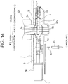
- an operation member 51B having a T-shape in cross section is provided inside a cylindrical member 51A so as to be operable in an axial direction thereof through the intermediation of a compression spring 51C.
- a contact portion 51a is provided, which is constructed of a pressing portion formed of an elastic member.
- the contact portion 51a is formed so as to protrude forward from an end portion of the cylindrical member 51A, and is made of such a material that the contact portion 51a is deformed and pressed when a tip end 21A of the seal case 21 abuts against the contact portion 51a, and then the seal case 21 is slightly moved (biased) back in a direction of the original position of the seal case 21.
- the positioning member 51 is not limited to the structure using the cylindrical member 51A, the compression spring 51C, and the like described above.
- the positioning member 51 may have a structure using only an integrally molded member having a rod shape or a T-shape in cross section, which is made of a rubber or resin material, or using only a spring. With this structure, actions and effects similar to those described above can be obtained.
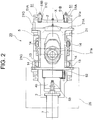
- FIG. 2 is a bottom view of FIG. 1 .
- the base frame 2 is provided with the well-known stopper 52 pivotable only by 90 degrees from a horizontal direction to a vertical direction and vice versa.
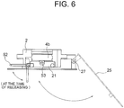
- a plate-like heat insulating cover 25 is provided pivotably toward the base frame 2 through the intermediation of an axial support portion 27 as illustrated in FIG. 6 .
- the stopper 52 is used for limiting a sliding range of the seal case 21 by causing the seal case 21 to abut against a protrusion or the like (not shown) during sliding.
- the heat insulating cover 25 is allowed to assume a closing state when the stopper 52 is situated at a horizontal position (solid line), and is not allowed to assume the closing state when situated at a vertical position (dotted line) .
- the positioning members 51 for determining the arrangement location X of the seal case 21, and the stopper 52 for fixing the seal case 21 at the arrangement location X are provided to the base frame 2, while the pusher 53 for pushing the seal case 21 is provided to the slide case 4 or the guide piece 4b. Therefore, when the slide case 4 or the guide piece 4b is slid in the surface pressure application direction by the actuator 7, as illustrated in FIGS. 3 and 4 , the seal case 21 is moved to the arrangement location X together with the slide case 4 by the pusher 53, and the stopper 52 is fitted to the seal case 21 that has been moved to the arrangement location X, with the result that the seal case 21 can be fixed at the arrangement location X.
- the positioning members 51 are disposed opposite to the stopper 52 with respect to the sliding direction of the slide case 4 or the guide piece 4b.
- a spring holder 30 is operably held on the base frame 2 through the intermediation of springs 12, and movable members 14 such as rollers, which are provided on both sides of the seal case 21, are slidably joined to support surfaces 13 formed in bottom surfaces of the spring holder 30. Therefore, the slidingmovement of the seal case 21 causes the movable members 14 to move on the support surfaces 13. Accordingly, the spring holder 30 moves upward and downward to apply and release the surface pressure.
- the slide case 4 is temporarily slid in a direction opposite to a surface pressure release direction so that the seal case 21 situated at the arrangement location X is biased by the pusher 53 in the direction opposite to the surface pressure release direction, and the stopper 52 that is easy to operate in this state is pivoted toward the dotted line of FIG. 6 and released. Then, the slide case 4 and the seal case 21 are slid in the surface pressure release direction, with the result that the surface pressure can be released.
- FIGS. 10 to 13 illustrate a second embodiment of the present invention, which is different from the above-mentioned first embodiment illustrated in FIGS. 1 to 8 .
- the same components as those in the first embodiment are represented by the same reference symbols to omit description thereof, and thus only differences from the first embodiment are described.
- the positioning member 51 and the pusher 53 of the first embodiment are arranged in an opposite manner.
- the positioning member 51 is positioned on the actuator 7 side of the base frame 2, and the pusher 53 is provided on a tip end 4A side of the slide case 4, which is opposite to the actuator 7.
- the stopper 52 is disposed at a position opposite to the case of FIG. 1 , that is, on the tip end 4A side of the base frame 2, which is a position opposite to the position of the actuator 7.
- the slide case 4 is drawn by the actuator 7 toward the left of FIG. 10 so that the seal case 21 is moved toward the left together with the seal plate 6 by the pusher 53, and a tip end 21M (illustrated in FIG. 10 ) of the seal case 21 abuts against the contact portions 51a of the positioning members 51, with the result that the surface pressure is applied in a manner similar to the case described above.
- the subsequent operation for the positioning members 51 is similar to that in the first embodiment described above, and description thereof is therefore omitted herein.
- the slide valve device for automatic surface pressure application and the surface pressure application method therefor according to the present invention are employed as means for controlling outflow of a molten metal between the respective vessels or the like in continuous casting facilities.
Landscapes
- Engineering & Computer Science (AREA)
- Mechanical Engineering (AREA)
- Casting Support Devices, Ladles, And Melt Control Thereby (AREA)
Claims (4)
- Schieberventilvorrichtung für eine automatische Flächendruckvorrichtung, aufweisend:eine feste Platte (3), die in einem Grundrahmen (2) befestigt ist, der auf einer unteren Bodenfläche (1a) eines Behälters für Metallschmelze (1) montiert ist;ein Gleitgehäuse (4) mit einer Gleitplatte (5), wobei das Gleitgehäuse (4) unterhalb der festen Platte (3) vorgesehen ist, um durch ein Stellglied (7) verschiebbar zu sein;ein Dichtungsgehäuse (21), das unterhalb des Gleitgehäuses (4) vorgesehen ist, wobei das Dichtungsgehäuse (21) eine Dichtungsplatte (6) oder eine Dichtungsplatte (6) und eine Schussdüse (21 a) umfasst; undein bewegbares Element (14), das an jedem Seitenabschnitt des Dichtungsgehäuses (21) vorgesehen ist, um auf einer Auflagefläche (13) bewegbar zu sein, die an jedem Seitenabschnitt des Grundrahmens (2) angeordnet ist,wobei das Gleitgehäuse (4) und das Dichtungsgehäuse (21) durch das Stellglied (7) verschiebbar sind, so dass ein Flächendruck aufbringbar und lösbar ist,wobei der Grundrahmen (2) aufweist:ein Positionierelement (51) zum Bestimmen eines Anordnungsorts (X) des Dichtungsgehäuses (21); undeinen Anschlag (52) zum Befestigen des Dichtungsgehäuses (21) an dem Anordnungsort (X), undwobei das Gleitgehäuse (4) oder ein Führungsstück einen Schieber (53) zum gemeinsamen Verschieben des Dichtungsgehäuses (21) und des Gleitgehäuses (4) aufweist, wenn das Gleitgehäuse (4) in einer Beaufschlagungsrichtung des Flächendrucks verschoben wird.
- Schieberventilvorrichtung für eine automatische Flächendruckvorrichtung nach Anspruch 1, wobei das Positionierelement (51) und der Anschlag (52) so angeordnet sind, dass sie das Dichtungsgehäuse (21) in Bezug auf eine Gleitrichtung des Gleitgehäuses (4) beidseitig umschließen.
- Schiebeventilvorrichtung für eine automatische Flächendruckvorrichtung nach Anspruch 1 oder 2, wobei ein Kontaktabschnitt (51 a) des Positionierelements (51) in Bezug auf das Dichtungsgehäuse (21) einen Druckabschnitt mit Elastizität bildet.
- Verfahren zum Aufbringen eines Flächendrucks für eine Schieberventilvorrichtung für eine automatische Flächendruckvorrichtung,
wobei die Schieberventilvorrichtung zum automatischen Aufbringen des Flächendrucks umfasst:eine feste Platte (3), die in einem Grundrahmen (2) befestigt ist, der auf einer unteren Bodenfläche (1a) eines Behälters für Metallschmelze (1) montiert ist;ein Gleitgehäuse (4) mit einer Gleitplatte (5), wobei das Gleitgehäuse (4) unterhalb der festen Platte (3) vorgesehen ist, um durch ein Stellglied (7) verschiebbar zu sein;ein Dichtungsgehäuse (21), das unterhalb des Gleitgehäuses (4) vorgesehen ist, wobei das Dichtungsgehäuse (21) eine Dichtungsplatte (6) oder eine Dichtungsplatte (6) und eine Schussdüse (21 a) umfasst; undein bewegbares Element (14), das an jedem Seitenabschnitt des Dichtungsgehäuses (21) vorgesehen ist, um auf einer Auflagefläche (13) bewegbar zu sein, die an jedem Seitenabschnitt des Grundrahmens (2) angeordnet ist,wobei das Gleitgehäuse (4) und das Dichtungsgehäuse (21) durch das Stellglied (7) verschiebbar sind, so dass ein Flächendruck aufbringbar und lösbar ist,wobei der Grundrahmen (2) der Gleitventilvorrichtung zum automatischen Aufbringen des Flächendrucks umfasst:ein Positionierelement (51) zum Bestimmen eines Anordnungsorts (X) des Dichtungsgehäuses (21); undeinen Anschlag (52) zum Fixieren des Dichtungsgehäuses (21) an der Anordnungsstelle (X),wobei das Gleitgehäuse (4) oder ein Führungsstück der Gleitventilvorrichtung zum automatischen Aufbringen des Flächendrucks einen Schieber (53) zum Schieben das Dichtungsgehäuse (21) umfasst,wobei das Verfahren zum Aufbringen des Flächendrucks aufweist:Verschieben des Gleitgehäuses (4) in einer Beaufschlagungsrichtung des Flächendrucks um das Dichtungsgehäuse (21) zusammen mit dem Gleitgehäuse (4) durch die Vermittlung des Schiebers (53) zu dem Anordnungsort (X) zu bewegen; undAnbringen des Anschlags (52) an dem Dichtungsgehäuse (21), das zu dem Anordnungsort (X) bewegt wurde, um das Dichtungsgehäuse (21) an dem Anordnungsort (X) zu befestigen.
Applications Claiming Priority (2)
| Application Number | Priority Date | Filing Date | Title |
|---|---|---|---|
| JP2009294034A JP5309011B2 (ja) | 2009-12-25 | 2009-12-25 | 自動面圧負荷スライドバルブ装置およびその面圧負荷方法 |
| PCT/JP2010/071462 WO2011077912A1 (ja) | 2009-12-25 | 2010-12-01 | 自動面圧負荷スライドバルブ装置およびその面圧負荷方法 |
Publications (3)
| Publication Number | Publication Date |
|---|---|
| EP2463045A1 EP2463045A1 (de) | 2012-06-13 |
| EP2463045A4 EP2463045A4 (de) | 2017-01-18 |
| EP2463045B1 true EP2463045B1 (de) | 2018-03-21 |
Family
ID=44195449
Family Applications (1)
| Application Number | Title | Priority Date | Filing Date |
|---|---|---|---|
| EP10839147.5A Not-in-force EP2463045B1 (de) | 2009-12-25 | 2010-12-01 | Gleitventilvorrichtung zur automatischen oberflächendruckbeaufschlagung sowie oberflächendruckbeaufschlagungsverfahren |
Country Status (4)
| Country | Link |
|---|---|
| US (1) | US8539977B2 (de) |
| EP (1) | EP2463045B1 (de) |
| JP (1) | JP5309011B2 (de) |
| WO (1) | WO2011077912A1 (de) |
Families Citing this family (6)
| Publication number | Priority date | Publication date | Assignee | Title |
|---|---|---|---|---|
| JP5283772B1 (ja) * | 2012-06-28 | 2013-09-04 | 品川リフラクトリーズ株式会社 | 自動面圧負荷スライドバルブ装置 |
| CH707075B1 (de) * | 2012-10-11 | 2021-01-15 | Refractory Intellectual Property Gmbh & Co Kg | Schiebeverschluss für ein Metallschmelze enthaltendes Gefäss. |
| JP5742992B1 (ja) * | 2014-03-13 | 2015-07-01 | 品川リフラクトリーズ株式会社 | スラブ連続鋳造用装置 |
| JP5958566B2 (ja) * | 2015-01-16 | 2016-08-02 | 品川リフラクトリーズ株式会社 | スラブ連続鋳造用装置 |
| JP6467511B2 (ja) * | 2015-08-27 | 2019-02-13 | 黒崎播磨株式会社 | スライド金枠の位置決め機構 |
| JP2018012140A (ja) * | 2016-07-11 | 2018-01-25 | ユニバーサル製缶株式会社 | 缶成形装置 |
Family Cites Families (11)
| Publication number | Priority date | Publication date | Assignee | Title |
|---|---|---|---|---|
| AT298708B (de) * | 1964-11-25 | 1972-04-15 | Benteler Geb Paderwerk | Regelbarer bodenverschlusz fuer stahl-gieszpfannen |
| CH579485A5 (de) * | 1975-01-28 | 1976-09-15 | Metacon Ag | |
| US4415103A (en) * | 1979-09-07 | 1983-11-15 | Uss Engineers And Consultants, Inc. | Full throttle valve and method of tube and gate change |
| US4573616A (en) * | 1982-05-24 | 1986-03-04 | Flo-Con Systems, Inc. | Valve, clamp, refractory and method |
| JP3313478B2 (ja) * | 1993-09-14 | 2002-08-12 | 住友重機械ハイマテックス株式会社 | スライドゲートプレートの装着方法及びそのための装置 |
| ATE178823T1 (de) * | 1995-02-17 | 1999-04-15 | Stopinc Ag | Schieberverschluss-system für einen metallschmelze enthaltenden behälter |
| GB9509014D0 (en) * | 1995-05-03 | 1995-06-21 | Flogates Ltd | Improved sliding gate valve |
| JP4095143B2 (ja) * | 1997-12-19 | 2008-06-04 | 黒崎播磨株式会社 | スライディングノズル装置 |
| DE10033904A1 (de) * | 2000-07-12 | 2002-01-31 | Stopinc Ag Huenenberg | Schieberverschluss zum Vergiessen von Metallschmelze, sowie eine dazugehörige feuerfeste Platteneinheit |
| JP4757714B2 (ja) | 2006-06-07 | 2011-08-24 | 品川リフラクトリーズ株式会社 | 自動面圧負荷スライドバルブ装置 |
| PL2173506T3 (pl) * | 2007-07-16 | 2011-10-31 | Stopinc Ag | Zasuwa do kadzi odlewniczej zawierającej płynny metal |
-
2009
- 2009-12-25 JP JP2009294034A patent/JP5309011B2/ja active Active
-
2010
- 2010-12-01 WO PCT/JP2010/071462 patent/WO2011077912A1/ja not_active Ceased
- 2010-12-01 US US13/496,352 patent/US8539977B2/en not_active Expired - Fee Related
- 2010-12-01 EP EP10839147.5A patent/EP2463045B1/de not_active Not-in-force
Non-Patent Citations (1)
| Title |
|---|
| None * |
Also Published As
| Publication number | Publication date |
|---|---|
| US8539977B2 (en) | 2013-09-24 |
| WO2011077912A1 (ja) | 2011-06-30 |
| EP2463045A1 (de) | 2012-06-13 |
| JP2011131253A (ja) | 2011-07-07 |
| EP2463045A4 (de) | 2017-01-18 |
| US20120175542A1 (en) | 2012-07-12 |
| JP5309011B2 (ja) | 2013-10-09 |
Similar Documents
| Publication | Publication Date | Title |
|---|---|---|
| EP2463045B1 (de) | Gleitventilvorrichtung zur automatischen oberflächendruckbeaufschlagung sowie oberflächendruckbeaufschlagungsverfahren | |
| EP2039445B1 (de) | Schieberventil zum aufbringen eines automatischen oberflächendrucks | |
| US10784599B2 (en) | Connection clip | |
| JP5860455B2 (ja) | フリップチューブの自動開口装置 | |
| US7237427B2 (en) | Pressing tool for the pressing-together of workpieces | |
| CN104703731B (zh) | 位于包含金属熔液的容器的排出口上的滑锁以及用于在滑锁中压下闸板的方法 | |
| US6629466B2 (en) | Test specimen holder | |
| JP6467511B2 (ja) | スライド金枠の位置決め機構 | |
| US11766717B2 (en) | Sliding gate device | |
| JP2019013938A (ja) | スライディングゲート装置 | |
| US20080272157A1 (en) | Sliding Nozzle Device and Pouring Device | |
| US7258256B2 (en) | Surface pressure load device of slide valve | |
| WO2011125660A1 (ja) | 押圧力測定装置 | |
| KR20180057416A (ko) | 슬라이드 게이트의 면압풀림 방지장치 | |
| CA2969198C (en) | A slide metal frame-drive unit coupling position switching mechanism for a sliding nozzle apparatus | |
| JP2011025261A (ja) | スライディングノズル装置 | |
| JP6470550B2 (ja) | スライディングノズル装置のスライド金枠と駆動装置との連結切り替え構造 | |
| JP2012166257A (ja) | スライディングノズル装置 | |
| WO2023145463A1 (ja) | スライディングノズル装置 | |
| JP2011104606A (ja) | プレートれんがの固定機構 | |
| JP2003200257A (ja) | スライドバルブの面圧負荷装置 | |
| JP2011212703A (ja) | スライディングノズル装置 |
Legal Events
| Date | Code | Title | Description |
|---|---|---|---|
| PUAI | Public reference made under article 153(3) epc to a published international application that has entered the european phase |
Free format text: ORIGINAL CODE: 0009012 |
|
| 17P | Request for examination filed |
Effective date: 20120309 |
|
| AK | Designated contracting states |
Kind code of ref document: A1 Designated state(s): AL AT BE BG CH CY CZ DE DK EE ES FI FR GB GR HR HU IE IS IT LI LT LU LV MC MK MT NL NO PL PT RO RS SE SI SK SM TR |
|
| RIN1 | Information on inventor provided before grant (corrected) |
Inventor name: OSADA, MOTOTSUGU Inventor name: TAKATA, ATSUSHI Inventor name: YAMAMOTO, KENJI |
|
| DAX | Request for extension of the european patent (deleted) | ||
| RA4 | Supplementary search report drawn up and despatched (corrected) |
Effective date: 20161215 |
|
| RIC1 | Information provided on ipc code assigned before grant |
Ipc: B22D 11/10 20060101ALI20161209BHEP Ipc: B22D 41/34 20060101ALI20161209BHEP Ipc: B22D 41/40 20060101AFI20161209BHEP |
|
| GRAP | Despatch of communication of intention to grant a patent |
Free format text: ORIGINAL CODE: EPIDOSNIGR1 |
|
| INTG | Intention to grant announced |
Effective date: 20171011 |
|
| GRAS | Grant fee paid |
Free format text: ORIGINAL CODE: EPIDOSNIGR3 |
|
| GRAA | (expected) grant |
Free format text: ORIGINAL CODE: 0009210 |
|
| AK | Designated contracting states |
Kind code of ref document: B1 Designated state(s): AL AT BE BG CH CY CZ DE DK EE ES FI FR GB GR HR HU IE IS IT LI LT LU LV MC MK MT NL NO PL PT RO RS SE SI SK SM TR |
|
| REG | Reference to a national code |
Ref country code: GB Ref legal event code: FG4D |
|
| REG | Reference to a national code |
Ref country code: CH Ref legal event code: EP |
|
| REG | Reference to a national code |
Ref country code: AT Ref legal event code: REF Ref document number: 980554 Country of ref document: AT Kind code of ref document: T Effective date: 20180415 |
|
| REG | Reference to a national code |
Ref country code: IE Ref legal event code: FG4D |
|
| REG | Reference to a national code |
Ref country code: DE Ref legal event code: R096 Ref document number: 602010049402 Country of ref document: DE |
|
| REG | Reference to a national code |
Ref country code: NL Ref legal event code: MP Effective date: 20180321 |
|
| PG25 | Lapsed in a contracting state [announced via postgrant information from national office to epo] |
Ref country code: HR Free format text: LAPSE BECAUSE OF FAILURE TO SUBMIT A TRANSLATION OF THE DESCRIPTION OR TO PAY THE FEE WITHIN THE PRESCRIBED TIME-LIMIT Effective date: 20180321 Ref country code: NO Free format text: LAPSE BECAUSE OF FAILURE TO SUBMIT A TRANSLATION OF THE DESCRIPTION OR TO PAY THE FEE WITHIN THE PRESCRIBED TIME-LIMIT Effective date: 20180621 Ref country code: FI Free format text: LAPSE BECAUSE OF FAILURE TO SUBMIT A TRANSLATION OF THE DESCRIPTION OR TO PAY THE FEE WITHIN THE PRESCRIBED TIME-LIMIT Effective date: 20180321 Ref country code: LT Free format text: LAPSE BECAUSE OF FAILURE TO SUBMIT A TRANSLATION OF THE DESCRIPTION OR TO PAY THE FEE WITHIN THE PRESCRIBED TIME-LIMIT Effective date: 20180321 Ref country code: CY Free format text: LAPSE BECAUSE OF FAILURE TO SUBMIT A TRANSLATION OF THE DESCRIPTION OR TO PAY THE FEE WITHIN THE PRESCRIBED TIME-LIMIT Effective date: 20180321 |
|
| REG | Reference to a national code |
Ref country code: LT Ref legal event code: MG4D |
|
| REG | Reference to a national code |
Ref country code: AT Ref legal event code: MK05 Ref document number: 980554 Country of ref document: AT Kind code of ref document: T Effective date: 20180321 |
|
| PG25 | Lapsed in a contracting state [announced via postgrant information from national office to epo] |
Ref country code: GR Free format text: LAPSE BECAUSE OF FAILURE TO SUBMIT A TRANSLATION OF THE DESCRIPTION OR TO PAY THE FEE WITHIN THE PRESCRIBED TIME-LIMIT Effective date: 20180622 Ref country code: SE Free format text: LAPSE BECAUSE OF FAILURE TO SUBMIT A TRANSLATION OF THE DESCRIPTION OR TO PAY THE FEE WITHIN THE PRESCRIBED TIME-LIMIT Effective date: 20180321 Ref country code: LV Free format text: LAPSE BECAUSE OF FAILURE TO SUBMIT A TRANSLATION OF THE DESCRIPTION OR TO PAY THE FEE WITHIN THE PRESCRIBED TIME-LIMIT Effective date: 20180321 Ref country code: RS Free format text: LAPSE BECAUSE OF FAILURE TO SUBMIT A TRANSLATION OF THE DESCRIPTION OR TO PAY THE FEE WITHIN THE PRESCRIBED TIME-LIMIT Effective date: 20180321 Ref country code: BG Free format text: LAPSE BECAUSE OF FAILURE TO SUBMIT A TRANSLATION OF THE DESCRIPTION OR TO PAY THE FEE WITHIN THE PRESCRIBED TIME-LIMIT Effective date: 20180621 |
|
| PG25 | Lapsed in a contracting state [announced via postgrant information from national office to epo] |
Ref country code: RO Free format text: LAPSE BECAUSE OF FAILURE TO SUBMIT A TRANSLATION OF THE DESCRIPTION OR TO PAY THE FEE WITHIN THE PRESCRIBED TIME-LIMIT Effective date: 20180321 Ref country code: IT Free format text: LAPSE BECAUSE OF FAILURE TO SUBMIT A TRANSLATION OF THE DESCRIPTION OR TO PAY THE FEE WITHIN THE PRESCRIBED TIME-LIMIT Effective date: 20180321 Ref country code: EE Free format text: LAPSE BECAUSE OF FAILURE TO SUBMIT A TRANSLATION OF THE DESCRIPTION OR TO PAY THE FEE WITHIN THE PRESCRIBED TIME-LIMIT Effective date: 20180321 Ref country code: NL Free format text: LAPSE BECAUSE OF FAILURE TO SUBMIT A TRANSLATION OF THE DESCRIPTION OR TO PAY THE FEE WITHIN THE PRESCRIBED TIME-LIMIT Effective date: 20180321 Ref country code: AL Free format text: LAPSE BECAUSE OF FAILURE TO SUBMIT A TRANSLATION OF THE DESCRIPTION OR TO PAY THE FEE WITHIN THE PRESCRIBED TIME-LIMIT Effective date: 20180321 Ref country code: PL Free format text: LAPSE BECAUSE OF FAILURE TO SUBMIT A TRANSLATION OF THE DESCRIPTION OR TO PAY THE FEE WITHIN THE PRESCRIBED TIME-LIMIT Effective date: 20180321 Ref country code: ES Free format text: LAPSE BECAUSE OF FAILURE TO SUBMIT A TRANSLATION OF THE DESCRIPTION OR TO PAY THE FEE WITHIN THE PRESCRIBED TIME-LIMIT Effective date: 20180321 |
|
| PG25 | Lapsed in a contracting state [announced via postgrant information from national office to epo] |
Ref country code: AT Free format text: LAPSE BECAUSE OF FAILURE TO SUBMIT A TRANSLATION OF THE DESCRIPTION OR TO PAY THE FEE WITHIN THE PRESCRIBED TIME-LIMIT Effective date: 20180321 Ref country code: SK Free format text: LAPSE BECAUSE OF FAILURE TO SUBMIT A TRANSLATION OF THE DESCRIPTION OR TO PAY THE FEE WITHIN THE PRESCRIBED TIME-LIMIT Effective date: 20180321 Ref country code: SM Free format text: LAPSE BECAUSE OF FAILURE TO SUBMIT A TRANSLATION OF THE DESCRIPTION OR TO PAY THE FEE WITHIN THE PRESCRIBED TIME-LIMIT Effective date: 20180321 |
|
| PG25 | Lapsed in a contracting state [announced via postgrant information from national office to epo] |
Ref country code: PT Free format text: LAPSE BECAUSE OF FAILURE TO SUBMIT A TRANSLATION OF THE DESCRIPTION OR TO PAY THE FEE WITHIN THE PRESCRIBED TIME-LIMIT Effective date: 20180723 |
|
| REG | Reference to a national code |
Ref country code: DE Ref legal event code: R097 Ref document number: 602010049402 Country of ref document: DE |
|
| PLBE | No opposition filed within time limit |
Free format text: ORIGINAL CODE: 0009261 |
|
| STAA | Information on the status of an ep patent application or granted ep patent |
Free format text: STATUS: NO OPPOSITION FILED WITHIN TIME LIMIT |
|
| PG25 | Lapsed in a contracting state [announced via postgrant information from national office to epo] |
Ref country code: DK Free format text: LAPSE BECAUSE OF FAILURE TO SUBMIT A TRANSLATION OF THE DESCRIPTION OR TO PAY THE FEE WITHIN THE PRESCRIBED TIME-LIMIT Effective date: 20180321 |
|
| 26N | No opposition filed |
Effective date: 20190102 |
|
| PG25 | Lapsed in a contracting state [announced via postgrant information from national office to epo] |
Ref country code: SI Free format text: LAPSE BECAUSE OF FAILURE TO SUBMIT A TRANSLATION OF THE DESCRIPTION OR TO PAY THE FEE WITHIN THE PRESCRIBED TIME-LIMIT Effective date: 20180321 |
|
| REG | Reference to a national code |
Ref country code: DE Ref legal event code: R119 Ref document number: 602010049402 Country of ref document: DE |
|
| REG | Reference to a national code |
Ref country code: CH Ref legal event code: PL |
|
| PG25 | Lapsed in a contracting state [announced via postgrant information from national office to epo] |
Ref country code: LU Free format text: LAPSE BECAUSE OF NON-PAYMENT OF DUE FEES Effective date: 20181201 Ref country code: MC Free format text: LAPSE BECAUSE OF FAILURE TO SUBMIT A TRANSLATION OF THE DESCRIPTION OR TO PAY THE FEE WITHIN THE PRESCRIBED TIME-LIMIT Effective date: 20180321 |
|
| REG | Reference to a national code |
Ref country code: IE Ref legal event code: MM4A |
|
| REG | Reference to a national code |
Ref country code: BE Ref legal event code: MM Effective date: 20181231 |
|
| PG25 | Lapsed in a contracting state [announced via postgrant information from national office to epo] |
Ref country code: FR Free format text: LAPSE BECAUSE OF NON-PAYMENT OF DUE FEES Effective date: 20181231 Ref country code: DE Free format text: LAPSE BECAUSE OF NON-PAYMENT OF DUE FEES Effective date: 20190702 Ref country code: IE Free format text: LAPSE BECAUSE OF NON-PAYMENT OF DUE FEES Effective date: 20181201 |
|
| PG25 | Lapsed in a contracting state [announced via postgrant information from national office to epo] |
Ref country code: BE Free format text: LAPSE BECAUSE OF NON-PAYMENT OF DUE FEES Effective date: 20181231 |
|
| PG25 | Lapsed in a contracting state [announced via postgrant information from national office to epo] |
Ref country code: LI Free format text: LAPSE BECAUSE OF NON-PAYMENT OF DUE FEES Effective date: 20181231 Ref country code: CH Free format text: LAPSE BECAUSE OF NON-PAYMENT OF DUE FEES Effective date: 20181231 |
|
| PG25 | Lapsed in a contracting state [announced via postgrant information from national office to epo] |
Ref country code: MT Free format text: LAPSE BECAUSE OF NON-PAYMENT OF DUE FEES Effective date: 20181201 |
|
| PG25 | Lapsed in a contracting state [announced via postgrant information from national office to epo] |
Ref country code: TR Free format text: LAPSE BECAUSE OF FAILURE TO SUBMIT A TRANSLATION OF THE DESCRIPTION OR TO PAY THE FEE WITHIN THE PRESCRIBED TIME-LIMIT Effective date: 20180321 |
|
| PG25 | Lapsed in a contracting state [announced via postgrant information from national office to epo] |
Ref country code: HU Free format text: LAPSE BECAUSE OF FAILURE TO SUBMIT A TRANSLATION OF THE DESCRIPTION OR TO PAY THE FEE WITHIN THE PRESCRIBED TIME-LIMIT; INVALID AB INITIO Effective date: 20101201 Ref country code: MK Free format text: LAPSE BECAUSE OF NON-PAYMENT OF DUE FEES Effective date: 20180321 |
|
| PG25 | Lapsed in a contracting state [announced via postgrant information from national office to epo] |
Ref country code: IS Free format text: LAPSE BECAUSE OF FAILURE TO SUBMIT A TRANSLATION OF THE DESCRIPTION OR TO PAY THE FEE WITHIN THE PRESCRIBED TIME-LIMIT Effective date: 20180721 |
|
| PGFP | Annual fee paid to national office [announced via postgrant information from national office to epo] |
Ref country code: GB Payment date: 20231102 Year of fee payment: 14 |
|
| PGFP | Annual fee paid to national office [announced via postgrant information from national office to epo] |
Ref country code: CZ Payment date: 20231116 Year of fee payment: 14 |
|
| PG25 | Lapsed in a contracting state [announced via postgrant information from national office to epo] |
Ref country code: CZ Free format text: LAPSE BECAUSE OF NON-PAYMENT OF DUE FEES Effective date: 20241201 |
|
| GBPC | Gb: european patent ceased through non-payment of renewal fee |
Effective date: 20241201 |
|
| PG25 | Lapsed in a contracting state [announced via postgrant information from national office to epo] |
Ref country code: GB Free format text: LAPSE BECAUSE OF NON-PAYMENT OF DUE FEES Effective date: 20241201 |