EP2463009B2 - Filteranordnung - Google Patents
Filteranordnung Download PDFInfo
- Publication number
- EP2463009B2 EP2463009B2 EP11191036.0A EP11191036A EP2463009B2 EP 2463009 B2 EP2463009 B2 EP 2463009B2 EP 11191036 A EP11191036 A EP 11191036A EP 2463009 B2 EP2463009 B2 EP 2463009B2
- Authority
- EP
- European Patent Office
- Prior art keywords
- filter
- housing
- frame
- filter element
- recess
- Prior art date
- Legal status (The legal status is an assumption and is not a legal conclusion. Google has not performed a legal analysis and makes no representation as to the accuracy of the status listed.)
- Active
Links
- 239000003570 air Substances 0.000 description 25
- 239000000463 material Substances 0.000 description 10
- 238000002485 combustion reaction Methods 0.000 description 7
- 238000009434 installation Methods 0.000 description 5
- 238000001914 filtration Methods 0.000 description 4
- 239000012530 fluid Substances 0.000 description 4
- 239000002245 particle Substances 0.000 description 4
- 230000002787 reinforcement Effects 0.000 description 4
- 238000004378 air conditioning Methods 0.000 description 2
- 238000007373 indentation Methods 0.000 description 2
- 239000007788 liquid Substances 0.000 description 2
- 235000019645 odor Nutrition 0.000 description 2
- 239000006096 absorbing agent Substances 0.000 description 1
- 230000001133 acceleration Effects 0.000 description 1
- 230000006978 adaptation Effects 0.000 description 1
- 238000007792 addition Methods 0.000 description 1
- 239000000853 adhesive Substances 0.000 description 1
- 238000004026 adhesive bonding Methods 0.000 description 1
- 230000001070 adhesive effect Effects 0.000 description 1
- 238000003915 air pollution Methods 0.000 description 1
- 239000012080 ambient air Substances 0.000 description 1
- 238000006243 chemical reaction Methods 0.000 description 1
- 230000006835 compression Effects 0.000 description 1
- 238000007906 compression Methods 0.000 description 1
- 238000009833 condensation Methods 0.000 description 1
- 230000005494 condensation Effects 0.000 description 1
- 230000001143 conditioned effect Effects 0.000 description 1
- 230000001419 dependent effect Effects 0.000 description 1
- 238000005516 engineering process Methods 0.000 description 1
- 238000003780 insertion Methods 0.000 description 1
- 230000037431 insertion Effects 0.000 description 1
- 230000006641 stabilisation Effects 0.000 description 1
- 238000011105 stabilization Methods 0.000 description 1
- XLYOFNOQVPJJNP-UHFFFAOYSA-N water Substances O XLYOFNOQVPJJNP-UHFFFAOYSA-N 0.000 description 1
Images

Classifications
-
- B—PERFORMING OPERATIONS; TRANSPORTING
- B01—PHYSICAL OR CHEMICAL PROCESSES OR APPARATUS IN GENERAL
- B01D—SEPARATION
- B01D46/00—Filters or filtering processes specially modified for separating dispersed particles from gases or vapours
- B01D46/10—Particle separators, e.g. dust precipitators, using filter plates, sheets or pads having plane surfaces
-
- B—PERFORMING OPERATIONS; TRANSPORTING
- B01—PHYSICAL OR CHEMICAL PROCESSES OR APPARATUS IN GENERAL
- B01D—SEPARATION
- B01D46/00—Filters or filtering processes specially modified for separating dispersed particles from gases or vapours
- B01D46/0084—Filters or filtering processes specially modified for separating dispersed particles from gases or vapours provided with safety means
- B01D46/009—Identification of filter type or position thereof, e.g. by transponders or bar codes
-
- B—PERFORMING OPERATIONS; TRANSPORTING
- B01—PHYSICAL OR CHEMICAL PROCESSES OR APPARATUS IN GENERAL
- B01D—SEPARATION
- B01D46/00—Filters or filtering processes specially modified for separating dispersed particles from gases or vapours
- B01D46/52—Particle separators, e.g. dust precipitators, using filters embodying folded corrugated or wound sheet material
- B01D46/521—Particle separators, e.g. dust precipitators, using filters embodying folded corrugated or wound sheet material using folded, pleated material
-
- B—PERFORMING OPERATIONS; TRANSPORTING
- B60—VEHICLES IN GENERAL
- B60H—ARRANGEMENTS OF HEATING, COOLING, VENTILATING OR OTHER AIR-TREATING DEVICES SPECIALLY ADAPTED FOR PASSENGER OR GOODS SPACES OF VEHICLES
- B60H3/00—Other air-treating devices
- B60H3/06—Filtering
- B60H3/0658—Filter elements specially adapted for their arrangement in vehicles
-
- B—PERFORMING OPERATIONS; TRANSPORTING
- B01—PHYSICAL OR CHEMICAL PROCESSES OR APPARATUS IN GENERAL
- B01D—SEPARATION
- B01D2265/00—Casings, housings or mounting for filters specially adapted for separating dispersed particles from gases or vapours
- B01D2265/02—Non-permanent measures for connecting different parts of the filter
- B01D2265/024—Mounting aids
- B01D2265/026—Mounting aids with means for avoiding false mounting
-
- B—PERFORMING OPERATIONS; TRANSPORTING
- B60—VEHICLES IN GENERAL
- B60H—ARRANGEMENTS OF HEATING, COOLING, VENTILATING OR OTHER AIR-TREATING DEVICES SPECIALLY ADAPTED FOR PASSENGER OR GOODS SPACES OF VEHICLES
- B60H3/00—Other air-treating devices
- B60H3/06—Filtering
- B60H3/0608—Filter arrangements in the air stream
- B60H2003/065—Details for holding filter elements in position
Definitions
- the invention relates to a filter arrangement with a filter element, such as a cabin air filter for a motor vehicle.
- a corresponding filter element is used to filter fluid flows or, in particular, gaseous media, for example to filter an air flow that is supplied to the vehicle interior of a motor vehicle.
- a filter element for filtering air for the interior of a motor vehicle Such filters are also referred to below as motor vehicle interior air filters or also interior filters or cabin air filters.
- filter media that are folded in a zigzag shape which are also referred to as pleated filter media, are predominantly used for vehicle interior air filters.
- By folding the filter medium used, depending on the fold height, the fold spacing and the degree of compression of these accordion-like fold packs of the various fold sections of the filter medium an increase in the filter surface through which the air stream flows can be made possible.
- reinforcement elements are often provided on the sides of the filter element along the filter pack made of the folded medium.
- These reinforcement elements are used for lateral fixation and stabilization of the zigzag-shaped filter medium and are attached to the lateral edges of the fold pack, for example by means of a suitable adhesive.
- the filter element with reinforcements or reinforcements attached in strips to the folded longitudinal sides can easily be inserted into a housing of a filter module or a corresponding filter receptacle, for example in a filter housing or an air conditioning system of a motor vehicle, without damaging it.
- Filters are also used in motor vehicles to separate particles from the intake air to internal combustion engines.
- the geometry and materials used in these filters are designed specifically for a specific type of motor vehicle. This is due, for example, to the fact that the requirements for the air flow rate, the flow resistance and the filter performance of the air filter depend on the type of internal combustion engine. Furthermore, the installation options are often dependent on both the internal combustion engine and the type of motor vehicle.
- a filter arrangement is known, the filter element of which has terminal recesses in opposite side bands, ie recesses which are open towards a head region of the filter element.
- rods on the housing engage in the terminal recesses.
- the DE 10 2005 048841 B3 a filter arrangement, the filter element of which has in its side band two openings or holes which are asymmetrical in relation to a height direction and into which a housing-side guide pin which extends between two adjacent fold surfaces engages in an assembled state.
- the filter element In order to make this intervention possible, the filter element must be pushed into the housing parallel to the longitudinal extent of the folds, in which the guide pins also extend.
- JP 2005 007361 A a filter element, each having two cuts in opposite side bands, which serve to make the filter element bendable in order to mount it transversely to the length of the pleats in a mounting slot which is difficult to access.
- the object of the invention is to provide an improved filter arrangement with a filter element and housing for receiving the filter element, the filter element of which can only be installed in the housing in a specific orientation and is assembly-optimized. This task is accomplished by a filter arrangement with the Features of independent claim 1 solved.
- the filter arrangement according to the invention has a filter element and a filter mount.
- a filter element has a pack of folds and a frame that at least partially surrounds the pack of folds, the frame comprising at least one recess for a projection of a housing for the filter element.
- the pack of folds can have a filter medium which is bent in a zigzag or wave shape and extends in one plane and is arranged on the frame.
- the frame has at least one groove-shaped recess for engaging a projection of a housing.
- a filter medium that extends in a zigzag shape and is bent in one plane has fold edges between which straight fold sections preferably extend. The shape corresponds to that of a bellows. If, instead of the folds or kinks, curves are provided that merge into one another directly or via straight intermediate areas, the result is a wavy filter medium shape. Regardless of the zigzag or wavy shape, the fold pack extends overall in one plane.
- a frame preferably made of a plastic material, is provided to stabilize the filter medium.
- the filter medium is fastened to this frame, for example by gluing, pushing into a groove, by means of rivets, clips or the like.
- the frame allows the filter media to be attached tightly and tightly in a housing.
- the frame is formed from the same material as the filter media.
- the filter element is designed in particular as a cabin air filter for a motor vehicle. During operation of the filter element, a fluid to be filtered, such as air for the vehicle interior, is passed through the fold pack in a predetermined flow direction.
- the filter element can also be an engine air filter.
- An embodiment as a household filter is also conceivable.
- the proposed filter element makes it more difficult to use filter elements from other manufacturers in the housing with little design effort. This ensures a consistent quality of the filter performance.
- the groove-shaped recess is designed in such a way that the projection can pierce the edge in the direction of the fold pack.
- the recess is formed as a cut from an edge of the rim.
- the incision is preferably at least a quarter of the height of the frame, the height of the frame essentially corresponding to a height of the fold pack.
- the height of the fold pack depends on the width of the fold sections and the fold density.
- the frame encloses the filter medium at the edge, as a result of which an all-round seal can be achieved between the filter medium and the frame.
- the frame has a rectangular shape.
- the filter element can be inserted into a receptacle in the manner of a drawer. If the filter element is inserted flat into a housing, the rectangular shape enables easy orientation and precise fitting of the filter element.
- the frame of the filter element comprises two side straps attached to fold edge profiles of the fold pack and two head straps attached to end fold sections of the fold pack and/or the side straps.
- the frame can be made from one piece of material or from several elements.
- the fold pack is molded or foamed around the frame.
- the recess is provided on a side band in such a way that the projection can penetrate between two adjacent fold sections in the fold pack.
- At least one recess is provided on each longitudinal side of the frame, for example on the side bands.
- the recesses allow for the engagement of projections from a housing into which the filter element is inserted. It can thereby be achieved that only one filter element with the corresponding recesses can be inserted into the housing. This can prevent the use of filter elements from other manufacturers that do not have this recess.
- the frame has at least one outer boundary surface which encloses an angle of between 0 degrees and 90 degrees with a plane of the fold pack.
- the frame is conically shaped at least in sections on the outside. It preferably has an outer boundary surface which encloses an angle of between 45 and 80 degrees with the plane in which the filter medium extends.
- a correspondingly inclined surface is provided on a corresponding housing for accommodating the filter element, filter elements that do not have this inclination, i.e. are more cuboid and not conical, can be prevented from being used, since they then collide with the inclination .
- the boundary surface is preferably part of a side band. Then the boundary surface intersects the pleat profiles.
- a suitable housing for receiving a filter element according to the invention has at least one projection which engages in the recess of the frame when the filter element is inserted into the housing.
- the housing preferably has a further projection which is arranged on a rod which is in particular detachably mounted in the housing.
- a housing for accommodating a filter can further have at least one first projection which engages in the recess of the frame when the filter element is inserted into the housing and/or have at least one second projection which engages in the folds or indentations of the filter medium when the filter element is inserted into the housing is.
- the first projection prevents a filter element from being inserted into the housing that does not have a corresponding recess. This prevents the use of unsuitable filter elements from other manufacturers.
- the second projection engages the filter media when it is inserted into the housing. As a result, only filter elements that have filter media with corresponding folds or indentations can be inserted into the housing. A filter element can therefore not be used even if the recesses are present in the frame, but a simply flat filter medium without a wavy or bellows-shaped contour is used.
- the second projection preferably has a wedge-shaped cross-sectional portion for engaging the filter media.
- the pointed side of the wedge-shaped cross-sectional part runs, for example, in the direction of a flow direction of the filter element.
- the wedge presses between the folds or corrugations of the filter medium and pushes them to the side. This prevents the filter medium from being placed on the folds or corrugations and thus denting.
- a plurality of second projections are preferably provided at a distance from one another which corresponds to one or more times the distance between the corrugations or folds. This prevents the use of filter media that have waves or folds that are incorrectly spaced. A coding is thus achieved via the division in the form of waves or folds of the filter medium. Third-party filter elements with the wrong pitch cannot be used. This prevents the intake air from being insufficiently filtered or the flow resistance of the filter element from being too great when using the wrong filter element, for example when filtering the combustion air of an engine, which can lead to damage to the combustion engine or poor exhaust gas values.
- the second projection can be arranged on a rod which is in particular detachably attached to the housing.
- the rod preferably extends parallel to the folds or corrugations of the filter medium of a filter element to be used. If the rod is detachably attached, this offers the advantage that the position of the second projection can be changed by inserting the rod at a desired location.
- the housing can be flexibly configured to accommodate filter elements of a specific geometry. In the case of a plurality of second projections, an adaptation to the fold or corrugation distance of a filter medium to be used can thus take place.
- the rod can be snapably attached to the housing.
- the interior of the housing may also have a slanted wall which encloses an angle of between 0 degrees and 90 degrees with a support surface for the fold pack or with a plane of the fold pack.
- the housing is, for example, tapered in some areas on the inside.
- a filter element that is also conically shaped can be used correctly, while a non-manufacturer, simply cuboid filter element cannot be used.
- a sloping boundary surface is preferably also provided on the housing, which then comes to rest against the sloping boundary surface of the filter element when the filter element is received. This also prevents the filter element from being installed counter to an intended flow direction, which, for example, increases the operational reliability of the filter and simplifies installation. A torsion-proof arrangement is thus also achieved.
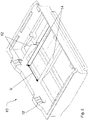
- the filter element 1 shows a schematic perspective representation of an embodiment of a filter element 1 .
- the filter element 1 has a fold pack 3 and a frame 7 .
- the shape of the frame 7 is derived from a cuboid, with a lateral boundary surface 9 being arranged at a slight incline.
- the frame 7 has a conical shape and has a trapezoidal cross-section parallel to the folds 5 .
- the boundary surface 9 encloses an angle ⁇ with a direction of flow through the fold pack 3 or the air filter 1 .
- the angle ⁇ is between 10 and 45 degrees.
- the frame 7 is formed from a plastic, for example. In this exemplary embodiment, the frame 7 laterally encloses the fold pack 3 .
- the fold pack 3 comprises filter material folded in a zigzag shape as the filter medium.
- the filter material can be a filter fleece material that is suitable for filtering raw fluid, for example interior air, outside air or combustion air for motor vehicles.
- the fold pack 2 can comprise a multi-layer filter material in which absorber particles are arranged between different layers.
- the filter medium in this exemplary embodiment is designed as a bellows or fold pack 3 which extends in a plane 4 . Substantially straight rectangular fold sections of the filter medium extend between the folds 5 .
- the filter medium thus has folds, in which figure 1 exemplary upper folding edges 5 are indicated. The distance between each two folded edges 5 of the filter medium is marked with a.
- the frame 7 here has two side straps 6, which are attached to the fold profiles of the fold pack 3 (not shown), and two head straps 2, which run around the fold pack 3 together with the side straps 6.
- the frame 7 of the filter element 1 has recesses 8 .
- These recesses 8 are here in the form of grooves or incisions.
- the recesses 8 are intended to engage projections when the filter element 1 is received in a housing.
- the recess 8 runs in a wedge shape.
- the wedge-shaped incision 8 preferably extends into the frame 7 by at least one third of the height h of the filter element 1.
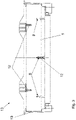
- FIG 2 shows a schematic perspective representation of an embodiment of a housing 10 for accommodating a filter element 1.
- the housing 10 is set up to accommodate the filter element 1 on the inside.
- First projections 12 extend in the housing 10 and are provided in the recesses 8 of the frame 7 of the filter element 1, as for example in FIG figure 1 shown to grip when received in the housing 10 .
- Second projections 14 are each arranged on a rod 15 and extend through the housing 10 parallel to the folds of a filter element 1 to be received. The projections 14 then engage in the folds 5 of the filter medium 3 when the filter element 1 is received. As a result, a filter medium 3 without folds 5 cannot be accommodated.
- the second projections 14 are wedge-shaped, so that they can grip between the folds 5 like a knife edge.
- the second projections 14 are each attached to a rod which is detachably arranged on the housing 10 . This allows the position of the rod to be varied.
- the second projections 14 are provided at a distance b which corresponds to a multiple of the fold distance a.
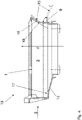
- the figure 3 shows a cross-sectional view of a filter arrangement 13 with a filter element 1 inserted into a housing 10. It can be seen how the projections 14 engage in the recesses 8 in the direction of the fold pack of the filter element.
- the cross section of the filter element 1 and the housing 10 is rectangular.
- the filter element 1 can be inserted into the box-shaped housing 10 with one of the headbands first.
- the second in the figure 2 indicated footbridge is removed here.
- no projections engage in the lower left and right recesses 8 .
- FIG 4 a side sectional view of the filter arrangement 13 with the filter element 1 inserted is shown. One looks at one of the side bands 2. A possible flow direction d for the fluid to be filtered, such as air, is also indicated.
- the level of the filter element 1 runs in the representation of figure 4 horizontal.
- the housing 10 has a sloping inner wall 16 which is adapted to the sloping boundary surface 9 of the frame of the filter element 1 .
- the filter element 1 lies on the support surface 17 in the housing.
- the sloping boundary surface 9 and the sloping wall 16 prevent the filter element 1 from being inserted into the housing 10 with the wrong orientation.
- the beveled wall is part of a closure flap 15, which is an installation and removal opening of the housing 10 closes or releases. This is indicated by the round arrows.
- the sloping wall 16 on the inside or the closure flap 15 is rounded.
- the bend 18 presses on the boundary surface 9 and fixes the filter element 1 in the housing 10 when the flap 15 is closed.
- the filter arrangement 13 is preferably arranged in the vehicle in such a way that the direction of insertion coincides with the plane of the fold pack and runs perpendicularly, ie parallel to the gravitational acceleration g. Then the closure flap 15 is also provided at the bottom, so that the slope 9 of the frame 16 forms a drain for liquid collected in the filter element 1 .
- the liquid can be, for example, splash or condensation water.
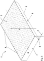
- the figure 5 shows a further perspective view of the filter element 1.
- the direction of flow d is indicated.
- the recesses 8 are both on the oblique side band and on the other (in the figure 5 concealed) sideband provided. At least two recesses 8 are provided on the frame 7 .
- the present invention has been explained in more detail on the basis of preferred exemplary embodiments, it is not limited thereto but can be modified in many ways. It is possible to select geometries other than those shown for filter elements and in particular for the headbands.
- the conditions at the installation site of the filter can be taken into account.
- the materials mentioned for the frame or the side and head band material and the filter medium are also only to be understood as examples.
- the recesses can have any shape, for example round, oval, triangular or rectangular.
- the recesses can also be formed in the manner of an opening or a hole in the frame.
Description
- Die Erfindung betrifft eine Filteranordnung mit einem Filterelement, wie zum Beispiel einen Innenraumluftfilter für ein Kraftfahrzeug.
- Ein entsprechendes Filterelement dient der Filterung von Fluidströmungen oder insbesondere gasförmigen Medien, beispielsweise zur Filterung einer Luftströmung, die dem Fahrzeuginnenraum eines Kraftfahrzeugs zugeführt wird. Obwohl auf beliebige Filterelemente und -anordnungen anwendbar, wird die vorliegende Erfindung sowie die ihr zugrunde liegende Problematik nachfolgend für ein Filterelement zur Filterung von Luft für den Innenraum eines Kraftfahrzeugs beschrieben. Solche Filter werden nachfolgend auch kurz als KFZ-Innenraumluftfilter oder auch Innenraumfilter bzw. Kabinenluftfilter bezeichnet.
- Die zunehmende Luftverunreinigung, insbesondere in Großstädten, in Verbindung mit dem Einsatz moderner Klimaanlagen macht es wünschenswert und auch erforderlich, die von außen in den Innenraum eines Kraftfahrzeuges geleitete und aufbereitete bzw. klimatisierte Luft mittels geeigneter Filter zu reinigen. Hierfür kommen beispielsweise Partikelfilter, Geruchsfilter oder deren Kombination miteinander in Betracht, die in der Luft enthaltene Schwebstoffe, Partikel und Gerüche aus der Umgebungsluft möglichst gut herausfiltern bzw. absorbieren sollen. Solche Filter zur Filterung von Luft für den Innenraum eines Kraftfahrzeuges sind in einer Vielzahl von Ausführungsformen und Varianten allgemein bekannt, so dass auf deren Aufbau und Funktionsweise nachfolgend nur kurz eingegangen wird.
- Da die Wirksamkeit von Filtern insbesondere von der Größe der von der Luft durchströmten Oberfläche des Filters abhängig ist, kommen für Kfz-Innenraumluftfilter überwiegend zickzackförmig gefaltete Filtermedien, die auch als plissierte Filtermedien bezeichnet werden, zum Einsatz. Durch die Faltung des verwendeten Filtermediums kann abhängig von der Faltungshöhe, dem Faltungsabstand und dem Grad des Zusammenstauchens dieser ziehharmonikaähnlichen Faltenpacks der verschiedenen Faltabschnitte des Filtermediums eine Vergrößerung der von dem Luftstrom durchströmten Filterfläche ermöglicht werden. Um entsprechende Filterelemente mit zickzackförmig gefalteten Filtermedien insbesondere montagetechnisch besser handhaben zu können, sind oft Verstärkungselemente an den Seiten des Filterelements entlang dem Filterpack aus dem gefalteten Medium vorgesehen. Diese Armierungselemente dienen der seitlichen Fixierung und Stabilisierung des zickzackförmigen Filtermediums und sind zum Beispiel mittels eines geeigneten Klebers an den seitlichen Kanten des Faltenpacks angebracht. Man spricht auch von Seitenbändern. Das Filterelement mit an den gefalteten Längsseiten streifenförmig angebrachten Armierungen oder Verstärkungen kann auf diese Weise montagetechnisch einfach ohne es zu beschädigen in ein Gehäuse eines Filtermoduls bzw. einer entsprechenden Filteraufnahme, beispielsweise in ein Filtergehäuse oder eine Klimaanlage eines Kraftfahrzeuges, eingefügt werden.
- Filter werden ferner in Kraftfahrzeugen eingesetzt, um Partikel aus der Zuluft zu Brennkraftmaschinen abzuscheiden. Diese Filter werden in ihrer Geometrie und den verwendeten Materialien spezifisch für einen bestimmten Kraftfahrzeugtyp vorgesehen. Dies liegt beispielsweise daran, dass die Anforderungen an die Luftdurchsatzmenge, den Strömungswiderstand und die Filterleistung des Luftfilters vom Brennkraftmaschinentyp abhängig sind. Ferner sind die Einbaumöglichkeiten oft sowohl von der Brennkraftmaschine als auch vom Kraftfahrzeugtyp abhängig.
- Ein Problem besteht darin, dass bei der Wartung von Kraftfahrzeugen aus Kostengründen manchmal Filterelemente von Fremdherstellern eingesetzt werden, die in der Filterleistung schlechter sind oder nicht genau in den Einbauraum passen. Durch diesen Umbau gelangt dann Luft, die unzureichend gefiltert ist, in den Innenraum oder zu der Brennkraftmaschine.
- Aus der
EP 2 108 432 A1 ist eine Filteranordnung bekannt, deren Filterelement jeweils in gegenüberliegenden Seitenbändern endständige, d. h. zu einem Kopfbereich des Filterelements hin offene, Ausnehmungen aufweist. In die endständigen Ausnehmungen greifen in einem Montagezustand gehäuseseitige Stäbe ein. - Ferner offenbart die
DE 10 2005 048841 B3 eine Filteranordnung, deren Filterelement in seinem Seitenband zwei im Bezug auf eine Höhenrichtung asymmetrisch vorliegende Öffnungen bzw. Löcher aufweist, in die in einem Montagezustand jeweils ein gehäuseseitiger Führungszapfen eingreift, der sich zwischen zwei banachbarten Faltenflächen erstreckt. Um diesen Eingriff zu ermöglichen, muss das Filterelement parallel zu der Faltenlängserstreckung in das Gehäuse eingeschoben werden, in der sich auch die Führungszapfen erstrecken. - Schließlich offenbart die
JP 2005 007361 A - Der Erfindung liegt die Aufgabe zugrunde, eine verbesserte Filteranordnung mit Filterelement und Gehäuse zur Aufnahme des Filterelements zur Verfügung zu stellen, dessen Filterelement nur in einer bestimmten Orientierung in das Gehäuse einbaubar ist und montageoptimiert ist.
Diese Aufgabe wird durch eine Filteranordnung mit den Merkmalen des unabhängigen Patentanspruchs 1 gelöst. - Die erfindungsgemäße Filteranordnung weist ein Filterelement sowie eine Filteraufnahme auf.
- Ein Filterelement weist ein Faltenpack und einen das Faltenpack zumindest teilweise umlaufenden Rahmen auf, wobei der Rahmen wenigstens eine Aussparung für einen Vorsprung eines Gehäuses für das Filterelement umfasst.
- Das Faltenpack kann ein zickzackförmig oder wellenförmig gebogenes sich in einer Ebene erstreckendes Filtermedium aufweisen, das an dem Rahmen angeordnet ist. Der Rahmen weist wenigstens eine nutförmige Aussparung zum Eingriff eines Vorsprungs eines Gehäuses auf. Ein zickzackförmig sich gebogen in einer Ebene erstreckendes Filtermedium weist dabei Faltkanten auf, zwischen denen sich bevorzugt gerade Faltabschnitte erstrecken. Die Form entspricht dabei der eines Faltenbalgs. Werden statt der Faltungen oder Knickstellen Rundungen vorgesehen, die direkt oder über gerade Zwischenbereiche ineinander übergehen, ergibt sich eine wellenförmige Filtermediumsgestalt. Unabhängig von der zickzackförmigen oder welligen Gestalt erstreckt sich das Faltenpack insgesamt in einer Ebene.
- Zur Stabilisierung des Filtermediums ist ein Rahmen bevorzugt aus einem Kunststoffmaterial vorgesehen. An diesem Rahmen ist das Filtermedium beispielsweise durch Ankleben, Einschieben in eine Nut, mittels Nieten, Klipsen oder dergleichen befestigt. Der Rahmen ermöglicht ein festes und dichtes Anbringen des Filtermediums in einem Gehäuse.
- In einer anderen Ausführungsform ist der Rahmen aus demselben Material gebildet wie das Filtermedium.
- Das Filterelement ist insbesondere als Innenraumluftfilter für ein Kraftfahrzeug ausgestaltet. Im Betrieb des Filterelements wird durch das Faltenpack in einer vorgegebenen Durchströmrichtung ein zu filterndes Fluid, wie Luft für den Fahrzeuginnenraum, durchgeleitet. Das Filterelement kann ferner ein Motorluftfilter sein. Denkbar ist auch eine Ausgestaltung als Haushaltsfilter.
- Das vorgeschlagene Filterelement erlaubt, bei geringem konstruktiven Aufwand den Einsatz herstellerfremder Filterelemente in das Gehäuse zu erschweren. Dadurch kann eine gleichbleibende Qualität der Filterleistung gewährleistet werden.
- Die nutförmige Aussparung ist derart ausgebildet, dass der Vorsprung in Richtung zu dem Faltenpack den Rand durchstoßen kann. Die Aussparung ist als Einschnitt von einer Kante des Randes aus ausgebildet. Vorzugsweise hat der Einschnitt mindestens ein Viertel der Höhe des Rahmens, wobei die Höhe des Rahmens im Wesentlichen einer Höhe des Faltenpacks entspricht. Die Höhe des Faltenpacks hängt dabei von der Breite der Faltabschnitte und der Faltungsdichte ab.
- Gemäß einer bevorzugten Ausführungsform fasst der Rahmen das Filtermedium randseitig ein, wodurch eine rundherum Abdichtung zwischen Filtermedium und Rahmen erzielt werden kann. Der Rahmen hat dabei eine rechteckförmige Gestalt. Dadurch kann das Filterelement schubladenartig in eine Aufnahme eingeführt werden. Wird das Filterelement flächig in ein Gehäuse eingesetzt, ermöglicht die Rechteckform eine einfache Orientierung und genaue Einpassung des Filterelements.
- Der Rahmen des Filterelements umfasst zwei an Faltkantenprofile des Faltenpacks angebrachte Seitenbänder und zwei an Endfaltenabschnitte des Faltenpacks und/oder den Seitenbändern angebrachte Kopfbänder.
- Der Rahmen kann materialeinstückig oder auch aus mehreren Elementen gefertigt sein. Beispielsweise ist das Faltenpack von dem Rahmen umspritzt oder umschäumt.
- Die Aussparung ist derart an einem Seitenband vorgesehen, dass der Vorsprung zwischen zwei benachbarte Faltenabschnitte in dem Faltenpack eindringen kann.
- Bei einer weiteren Ausführungsform ist an jeder Längsseite des Rahmens, beispielsweise an den Seitenbändern, wenigstens eine Aussparung vorgesehen. Die Aussparungen ermöglichen den Eingriff von Vorsprüngen von einem Gehäuse, in das das Filterelement eingesetzt wird. Dadurch kann erreicht werden, dass nur ein Filterelement mit den entsprechenden Aussparungen in das Gehäuse eingesetzt werden kann. Dadurch kann die Verwendung herstellerfremder Filterelemente, die diese Aussparung nicht aufweisen, verhindert werden.
- Gemäß einer weiteren Ausführungsform weist der Rahmen wenigstens eine äußere Begrenzungsfläche auf, die mit einer Ebene des Faltenpacks einen Winkel zwischen 0 Grad und 90 Grad einschließt. Zum Beispiel ist der Rahmen wenigstens abschnittsweise außen konisch geformt. Bevorzugt weist er eine äußere Begrenzungsfläche auf, die mit der Ebene in der sich das Filtermedium erstreckt, einen Winkel zwischen 45 und 80 Grad einschließt.
- Wird an einem entsprechenden Gehäuse für die Aufnahme des Filterelements eine entsprechend schräge Fläche vorgesehen, kann wiederum verhindert werden, dass Filterelemente, die diese Schräge nicht aufweisen, also eher quaderförmig und nicht konisch ausgebildet sind, eingesetzt werden können, da diese dann mit der Schräge kollidieren.
- Die Begrenzungsfläche ist vorzugsweise Teil eines Seitenbandes. Dann schneidet die Begrenzungsfläche die Faltenprofile.
- Ein geeignetes Gehäuse zur Aufnahme eines Filterelements gemäß der Erfindung hat wenigstens einen Vorsprung, der in die Aussparung des Rahmens eingreift, wenn das Filterelement in das Gehäuse eingesetzt ist.
- Das Gehäuse hat vorzugsweise einen weiteren Vorsprung, welcher an einem Stab angeordnet ist, der insbesondere lösbar in dem Gehäuse angebracht ist.
- Ein Gehäuse zur Aufnahme eines Filters kann ferner wenigstens einen ersten Vorsprung aufweisen, der in die Aussparung des Rahmens eingreift, wenn das Filterelement in das Gehäuse eingesetzt ist und/oder wenigstens einen zweiten Vorsprung aufweisen, der in die Falten bzw. Buchten des Filtermediums eingreift, wenn das Filterelement in das Gehäuse eingesetzt ist. Der erste Vorsprung verhindert dabei, dass ein Filterelement in das Gehäuse eingesetzt wird, das keine entsprechende Aussparung aufweist. Die Verwendung herstellerfremder ungeeigneter Filterelemente wird dadurch verhindert. Der zweite Vorsprung greift in das Filtermedium ein, wenn dieses in das Gehäuse eingesetzt ist. Dadurch können nur Filterelemente in das Gehäuse eingesetzt werden, die Filtermedien mit entsprechenden Falten bzw. Buchten aufweisen. Ein Filterelement kann somit auch dann nicht engesetzt werden, wenn die Aussparungen im Rahmen vorhanden sind, jedoch ein einfach ebenes Filtermedium ohne wellige bzw. faltenbalgförmige Kontur verwendet wird.
- Der zweite Vorsprung weist bevorzugt einen keilförmigen Querschnittsteil zum Eingriff in das Filtermedium auf. Die spitze Seite des keilförmigen Querschnittsteils verläuft beispielsweise in Richtung einer Durchströmrichtung des Filterelements. Dadurch drückt sich der Keil zwischen die Falten bzw. Wellen des Filtermediums und drückt diese zur Seite. Ein Aufsetzen auf die Falten bzw. Wellen und damit ein Verbeulen des Filtermediums wird somit verhindert.
- Bevorzugt sind mehrere zweite Vorsprünge in einem Abstand voneinander vorgesehen, der dem Einfachen oder Mehrfachen des Abstandes der Wellen bzw. Falten entspricht. Dadurch wird verhindert, dass Filtermedien eingesetzt werden, die Wellen oder Falten in einem falschen Abstand aufweisen. Es wird somit eine Codierung über die Teilung in Form von Wellen bzw. Falten des Filtermediums erreicht. Fremdhergestellte Filterelemente mit der Falschen Teilung können nicht eingesetzt werden. Dadurch wird vermieden, dass beim Einsatz eines falschen Filterelements beispielsweise bei der Filterung der Verbrennungsluft eines Motors, die Zuluft unzureichend gefiltert wird oder der Strömungswiderstand des Filterelements zu groß ist, was zu Schäden am Verbrennungsmotor oder zu schlechten Abgaswerten führen kann.
- Ferner kann der zweite Vorsprung an einem Stab angeordnet sein, der insbesondere lösbar am Gehäuse angebracht ist. Der Stab erstreckt sich dabei bevorzugt parallel zu den Falten bzw. Wellen des Filtermediums eines einzusetzenden Filterelements. Ist der Stab lösbar angebracht, bietet dies den Vorteil, dass die Position des zweiten Vorsprungs durch Einsetzen des Stabes an einer gewünschten Stelle verändert werden kann. Dadurch kann das Gehäuse für die Aufnahme von Filterelementen einer bestimmten Geometrie flexibel konfiguriert werden. Im Falle von mehreren zweiten Vorsprüngen kann somit eine Anpassung an den Falten- bzw. Wellenabstand eines einzusetzenden Filtermediums erfolgen. Der Stab kann rastbar an dem Gehäuse befestigt sein.
- Der Innenraum des Gehäuses kann ferner eine abgeschrägte Wand haben, welche mit einer Auflagefläche für das Faltenpack oder mit einer Ebene des Faltenpacks einen Winkel zwischen 0 Grad und 90 Grad einschließt.
- Das Gehäuse ist zum Beispiel innen bereichsweise konisch ausgeführt. Dadurch kann ein ebenfalls konisch geformtes Filterelement korrekt eingesetzt werden, während ein herstellerfremdes einfach quaderförmiges Filterelement nicht eingesetzt werden kann. Bevorzugt ist dabei analog zum Rahmen des Filterelements am Gehäuse ebenfalls eine schräge Begrenzungsfläche vorgesehen, die dann bei aufgenommenem Filterelement an der schrägen Begrenzungsfläche des Filterelements zum Anliegen kommt. Es wird dadurch auch der Einbau des Filterelements entgegen einer vorgesehenen Durchströmrichtung verhindert, was beispielsweise die Betriebssicherheit des Filters erhöht und den Einbau vereinfacht. Man erreicht somit auch eine verdrehsichere Anordnung.
- Weitere mögliche Implementierungen der Erfindung umfassen auch nicht explizit genannte Kombinationen von zuvor oder im Folgenden bezüglich der Ausführungsbeispiele beschriebenen Merkmale oder Ausführungsformen. Dabei wird der Fachmann auch Einzelaspekte als Verbesserungen oder Ergänzungen zu der jeweiligen Grundform der Erfindung hinzufügen.
- Im Weiteren wird die Erfindung anhand von Ausführungsbeispielen unter Bezugnahme auf die beigelegten Figuren näher erläutert.
- Es zeigt dabei:
-
Fig. 1 : eine schematische perspektivische Darstellung eines Filterelements; -
Fig. 2 : eine schematische perspektivische Darstellung eines Gehäuses zur Aufnahme des Filterelements; -
Fig. 3 : eine schematische Querschnittsdarstellung eines Gehäuses zur Aufnahme des Filterelements; -
Fig. 4 : eine weitere schematische Querschnittsdarstellung eines Gehäuses zur Aufnahme des Filterelements; und -
Fig. 5 : eine weitere schematische perspektivische Darstellung eines Filterelements. - In den Figuren bezeichnen dieselben Bezugszeichen gleiche oder funktionsgleiche Elemente, soweit nichts Gegenteiliges angegeben ist.
-
Fig. 1 zeigt eine schematische perspektivische Darstellung einer Ausführungsform eines Filterelements 1. Das Filterelement 1 weist ein Faltenpack 3 und einen Rahmen 7 auf. Der Rahmen 7 ist in der Form von einem Quader abgeleitet, wobei eine seitliche Begrenzungsfläche 9 etwas geneigt angeordnet ist. Dadurch weist der Rahmen 7 eine konische Form auf und hat einen trapezförmigen Querschnitt parallel zu den Faltungen 5 . Man erkennt, dass die Begrenzungsfläche 9 mit einer Durchströmrichtung durch das Faltenpack 3 bzw. den Luftfilter 1 einen Winkel α einschließt. Der Winkel α hat zwischen 10 und 45 Grad. Der Rahmen 7 ist beispielsweise aus einem Kunststoff gebildet. Der Rahmen 7 fasst bei diesem Ausführungsbeispiel das Faltenpack 3 seitlich ein. - Das Faltenpack 3 umfasst zickzackförmig gefaltetes Filtermaterial als Filtermedium. Das Filtermaterial kann ein Filter-Vlies-Material sein, das für die Filterung von Rohfluid, beispielsweise Innenraumluft, Außenluft oder auch Verbrennungsluft für Kraftfahrzeuge geeignet ist. Das Faltenpack 2 kann dabei ein mehrlagiges Filtermaterial umfassen, bei dem Absorberpartikel zwischen verschiedenen Schichten angeordnet sind. Insofern ist das Filtermedium bei diesem Ausführungsbeispiel als Faltenbalg oder Faltenpack 3 ausgeführt, der sich in einer Ebene 4 erstreckt. Zwischen den Faltungen 5 erstrecken sich dabei im wesentlichen gerade rechteckige Faltbschnitte des Filtermediums. Das Filtermedium weist dadurch Falten auf, wobei in der
Figur 1 beispielhaft obere Faltkanten 5 angedeutet sind. Der Abstand zwischen jeweils zwei Faltkanten 5 des Filtermediums ist mit a markiert. - Der Rahmen 7 hat hier zwei Seitenbänder 6, welche auf nicht dargestellte Faltenprofile des Faltenpacks 3 angebracht sind, und zwei Kopfbänder 2, welche zusammen mit den Seitenbändern 6 das Faltenpack 3 umlaufen.
- Der Rahmen 7 des Filterelements 1 weist Aussparungen 8 auf. Diese Aussparungen 8 sind hier in Form von Nuten oder Einschnitten ausgebildet. Die Aussparungen 8 sind vorgesehen, bei der Aufnahme des Filterelements 1 in einem Gehäuse mit Vorsprüngen in Eingriff zu kommen. Ausgehend von einer jeweiligen Kante 11 des Rahmens 7 oder des Seiten- oder Kopfbandes 6, 2 verläuft die Aussparung 8 keilförmig. Vorzugsweise reicht der keilförmige Einschnitt 8 mindestens um ein Drittel der Höhe h des Filterelements 1 in den Rahmen 7. Dadurch kann dann nur ein Filterelement 1 aufgenommen werden, das diese Aussparungen 8 aufweist. Bei einem Filterelement 1 dessen Rahmen 7 die Aussparungen 8 nicht aufweist, ist auf Grund der Kollision mit den Vorsprüngen keine Aufnahme im Gehäuse möglich. Dies wird im Zusammenhang mit dem Gehäuse, das anhand von
Figur 2 beschrieben wird, verständlich. -
Fig. 2 zeigt eine schematische perspektivische Darstellung einer Ausführungsform eines Gehäuses 10 zur Aufnahme eines Filterelements 1. Das Gehäuse 10 ist eingerichtet im Inneren das Filterelement 1 aufzunehmen. Erste Vorsprünge 12 erstrecken sich im Gehäuse 10 und sind vorgesehen, in die Aussparungen 8 des Rahmens 7 des Filterelements 1, wie es beispielsweise in derFigur 1 dargestellt ist, zu greifen, wenn dieses im Gehäuse 10 aufgenommen wird. - Zweite Vorsprünge 14 sind jeweils an einem Stab 15 angeordnet und erstrecken sich durch das Gehäuse 10 parallel zu den Falten eines aufzunehmenden Filterelements 1. Die Vorsprünge 14 greifen dann bei aufgenommenem Filterelement 1 in die Falten 5 des Filtermediums 3 ein. Dadurch kann ein Filtermedium 3 ohne Falten 5 nicht aufgenommen werden. Um das Eingreifen zwischen die Falten 5 bei der Aufnahme des Filterelements 1 zu erleichtern, sind die zweiten Vorsprünge 14 keilförmig ausgeführt, so dass sie messerschneidenartig zwischen die Falten 5 greifen können. Die zweiten Vorsprünge 14 sind bei dieser Ausführungsform jeweils an einem Stab angebracht, der lösbar am Gehäuse 10 angeordnet ist. Dadurch kann die Position des Stabs variiert werden. Die zweiten Vorsprünge 14 sind in einem Abstand b vorgesehen, der einem mehrfachen des Faltenabstands a entspricht. Dadurch wird verhindert, dass Filtermedien 1 in das Gehäuse 10 eingesetzt werden, die Wellen oder Falten 5 in einem falschen Abstand aufweisen. Es wird somit eine Codierung über die Teilung in Form von Wellen bzw. Falten 5 des Filtermediums 1 erreicht. Fremdhergestellte Filterelemente 1 mit der Falschen Teilung können nicht eingesetzt werden.
- Die
Figur 3 zeigt eine Querschnittsdarstellung einer Filteranordnung 13 mit einem in ein Gehäuse 10 eingesetzes Filterelement 1. Man erkennt, wie die Vorsprünge 14 in die Ausparungen 8 in Richtung zu dem Faltenpack des Filterelements eingreifen. Der Querschnitt des Filterelements 1 und des Gehäuses 10 ist rechteckig. Zum Beispiel kann das Filterelement 1 mit einem der Kopfbänder voran in das kastenförmige Gehäuse 10 eingeschoben werden. Der zweite in derFigur 2 angedeutete Steg ist hier entfernt. Somit greifen in die unteren linke und rechte Aussparung 8 keine Vorsprünge ein. - In der
Figur 4 ist eine seitliche Schnittansicht der Filteranordnung 13 mit eingesetztem Filterelement 1 dargestellt. Man blickt dabei auf eines der Seitenbänder 2. Es ist ferner eine mögliche Durchströmrichtung d für das zu filternde Fluid, wie Luft angegeben. Die Ebene des Filterlelements 1 verläuft in der Darstellung derFigur 4 horiziontal. Das Gehäuse 10 hat eine abgeschrägte innere Wand 16, die an die schräge Begrenzungsfläche 9 des Rahmens des Filterelements 1 angepasst ist. Das Filterelement 1 liegt auf der Auflagefläche 17 in den Gehäuse. Durch die schräge Begrenzungsfläche 9 und die schräge Wand 16 wird verhindert, dass das Filterelement 1 in falscher Orientierung in das Gehäuse 10 eingesetzt wird. - Die abgeschrägte Wand ist bei dem dargestellten Ausführungsbeispiel Teil einer Verschlussklappe 15, die eine Einbau- und Entnahmeöffnnung des Gehäuses 10 verschließt oder freigibt. Dies ist durch die runden Pfeile angedeutet. Die innenseitige schräge Wand 16 bzw. die Verschlussklappe 15 ist gerundet ausgeführt. Dadurch drückt die Biegung 18 auf die Begrenzungsfläche 9 und fixiert das Filterelement 1 in dem Gehäuse 10, wenn die Klappe 15 verschlossen ist..
- Bevorzugt ist die Filteranordnung 13 derart im Fahrzeug angeordnet, dass die Einschubrichtung mit der Ebene des Faltenpacks zusammenfällt und senkrecht, also parallel zur Erdbeschleunigung g verläuft. Dann ist ferner die Verschlussklappe 15 unten vorgesehen, sodass die Schräge 9 des Rahmens 16 einen Ablauf für in dem Filterlement 1 gesammelte Flüssigkeit bildet. Die Flüssigkeit kann zum Beispiel Spritz- oder Kondenswasser sein.
- Die
Figur 5 zeigt eine weitere perspektivische Ansicht des Filterlements 1. Es ist die Durchströmrichtung d angedeutet. Man blickt im Vergleich zurFigur 1 auf das (hintere) als schräge Begrenzungsfläche 9 des Rahmens 7 ausgebildete Seitenband. Die Aussparungen 8 sind sowohl an dem schrägen Seitenband wie auch an dem anderen (in derFigur 5 verdeckten) Seitenband vorgesehen. Es sind mindestens zwei Aussparungen 8 an dem Rahmen 7 vorgesehen. DieFigur 5 zeigt ferner den Winkel β, den die Begrenzungsfläche 9 bzw. das entsprechende Seitenband mit der Filterelementebene 4 einschließt. Es gilt dabei α + β = 90°. - Obwohl die vorliegende Erfindung anhand bevorzugter Ausführungsbeispiele näher erläutert wurde ist sie nicht darauf beschränkt, sondern vielfältig modifizierbar. Es können andere als die dargestellten Geometrien für Filterelemente und insbesondere der Kopfbänder gewählt werden. Dabei können die Gegebenheiten am Einbauort des Filters berücksichtigt werden. Die genannten Materialen für den Rahmen bzw. das Seiten- und Kopfbandmaterial und das Filtermedium sind ebenfalls nur beispielhaft zu verstehen. Die Aussparungen können beliebige Formen haben, z.B rund, oval, dreieckig oder rechteckig sein. Die Aussparungen können auch in der Art einer Öffnung oder eines Lochs in dem Rahmen ausgebildet sein.
Claims (4)
- Filteranordnung (13) mit einem Gehäuse (10) und mit einem Luftfilter (1), wobei der Luftfilter (1) ein Faltenpack (3) und einen das Faltenpack (3) zumindest teilweise umlaufenden Rahmen (7) hat, wobei der Rahmen (7) mit einer rechteckigen Gestalt wenigstens eine Aussparung (8) zum Eingriff eines Vorsprungs (12) des Gehäuses (10) aufweist, dadurch gekennzeichnet, dass die Aussparung (8) eine nutförmige Aussparung (8) ist, die als Einschnitt von einer Kante (11) des Randes (7) ausgebildet ist, die derart ausgebildet ist, dass der Vorsprung (12) in Richtung zu dem Faltenpack (3) den Rand (7) durchstoßen kann und der Luftfilter (1) schubladenartig in das Gehäuse (10) eingeführt werden kann, wobei der Rahmen (7) zwei an Faltkantenprofilen des Faltenpacks (3) angebrachte Seitenbänder (6) und zwei an Endfaltenabschnitten des Faltenpacks (3) und/oder den Seitenbändern (6) angebrachte Kopfbänder (2) umfasst, wobei die Aussparung (8) derart an einem Seitenband (6) vorgesehen ist, dass der Vorsprung (12) zwischen zwei benachbarte Faltenabschnitte in dem Faltenpack (3) eindringen kann, wobei das Gehäuse (10) mit wenigstens einem Vorsprung (12) in die Aussparung (8) des Rahmens (7) eingreift, wenn der Luftfilter (1) in das Gehäuse (10) eingesetzt ist.
- Filteranordnung (13) nach Anspruch 1, dadurch gekennzeichnet, dass der Rahmen (7) wenigstens eine äußere Begrenzungsfläche (9) aufweist, die mit einer Ebene (4) des Faltenpacks (3) einen Winkel (β) zwischen 0 Grad und 90 Grad einschließt.
- Filteranordnung (13) nach Anspruch 1 oder 2, ferner mit mindestens einem weiteren Vorsprung (14), welcher an einem Stab angeordnet ist, der insbesondere lösbar in dem Gehäuse (10) angebracht ist.
- Filteranordnung (13) nach einem der Ansprüche 1 - 3, wobei der Innenraum des Gehäuses (10) eine abgeschrägte Wand (16) aufweist, welche mit einer Auflagefläche (17) für den Luftfilter (1) oder einer Ebene (4) des Faltenpacks (3) einen Winkel (β) zwischen 0 Grad und 90 Grad einschließt.
Applications Claiming Priority (1)
| Application Number | Priority Date | Filing Date | Title |
|---|---|---|---|
| DE201010053758 DE102010053758A1 (de) | 2010-12-08 | 2010-12-08 | Filterelement und Gehäuse zur Aufnahme des Filterelements |
Publications (3)
| Publication Number | Publication Date |
|---|---|
| EP2463009A1 EP2463009A1 (de) | 2012-06-13 |
| EP2463009B1 EP2463009B1 (de) | 2019-04-03 |
| EP2463009B2 true EP2463009B2 (de) | 2022-04-13 |
Family
ID=45217289
Family Applications (1)
| Application Number | Title | Priority Date | Filing Date |
|---|---|---|---|
| EP11191036.0A Active EP2463009B2 (de) | 2010-12-08 | 2011-11-29 | Filteranordnung |
Country Status (3)
| Country | Link |
|---|---|
| EP (1) | EP2463009B2 (de) |
| CN (1) | CN102580424B (de) |
| DE (1) | DE102010053758A1 (de) |
Families Citing this family (15)
| Publication number | Priority date | Publication date | Assignee | Title |
|---|---|---|---|---|
| DE102010053758A1 (de) | 2010-12-08 | 2012-06-14 | Mann + Hummel Gmbh | Filterelement und Gehäuse zur Aufnahme des Filterelements |
| DE102014009706A1 (de) | 2013-07-12 | 2015-01-15 | Mann + Hummel Gmbh | Filterelement mit Halteflächen, Filter mit einem Filterelement und Filtergehäuse eines Filters |
| DE102013019327B4 (de) * | 2013-11-20 | 2023-06-01 | Mann+Hummel Gmbh | Filterelement mit Filterbalg und Verwendung des Filterelements |
| DE102014004738A1 (de) * | 2014-04-01 | 2015-10-01 | Daimler Ag | Filter mit Hybridrahmen |
| DE102014004740A1 (de) * | 2014-04-01 | 2015-10-01 | Daimler Ag | Luftfilter für eine Belüftungseinrichtung eines Kraftwagens |
| CN105289157A (zh) * | 2014-07-02 | 2016-02-03 | 张辰志 | 空气过滤器高效密封系统 |
| CN104807094B (zh) * | 2015-05-06 | 2018-07-10 | 安徽江淮汽车集团股份有限公司 | 一种汽车空调主机结构和一种汽车 |
| DE102015006027A1 (de) * | 2015-05-13 | 2016-11-17 | Mann + Hummel Gmbh | Filterelement für eine Filtereinrichtung |
| DE102016203342A1 (de) * | 2016-03-01 | 2017-09-07 | Mahle International Gmbh | Filterelement |
| US10744858B2 (en) | 2016-09-30 | 2020-08-18 | Nissan North America, Inc. | Vehicle body structure |
| CN110559751B (zh) * | 2018-06-05 | 2022-11-01 | 上海欧菲滤清器有限公司 | 板式空气过滤器、抽屉元件、以及空气过滤组件 |
| DE102018215235A1 (de) * | 2018-09-07 | 2020-03-12 | Mahle International Gmbh | Luftfilter und ein Verfahren zum Herstellen des Luftfilters |
| DE102020118293A1 (de) | 2020-07-10 | 2022-01-13 | Mann+Hummel Gmbh | Umgebungsluftreinigungsvorrichtung und Verwendung eines Filterelements in einer Umgebungsluftreinigungsvorrichtung |
| US11439938B2 (en) | 2020-10-30 | 2022-09-13 | Mann+Hummel Life Sciences & Environment Holding Singapore Pte. Ltd. | Reusable exoskeleton frame with U-shaped locking members and eco-friendly air filter element |
| EP4252887A1 (de) * | 2022-03-28 | 2023-10-04 | MANN+HUMMEL GmbH | Filtersystem und filterelement |
Citations (2)
| Publication number | Priority date | Publication date | Assignee | Title |
|---|---|---|---|---|
| JPH09136536A (ja) † | 1995-11-16 | 1997-05-27 | Kansei Corp | 空気清浄器のフイルタ構体 |
| EP1254694A1 (de) † | 2001-04-30 | 2002-11-06 | Valeo | Verfahren zur Herstellung einer Filtervorrichtung für Luftumlaufanlage insbesondere für Kraftfahrzeug |
Family Cites Families (39)
| Publication number | Priority date | Publication date | Assignee | Title |
|---|---|---|---|---|
| US3823533A (en) | 1973-09-27 | 1974-07-16 | Carrier Corp | Air filter retainer |
| GB1485072A (en) | 1975-05-15 | 1977-09-08 | Automotive Prod Co Ltd | Filter elements |
| US4420315A (en) | 1980-04-03 | 1983-12-13 | Kershaw Eli J | Nesting air filters |
| DE3817477A1 (de) | 1988-05-21 | 1989-11-30 | Kessler & Luch Produkte | Filtereinheit mit filteraufnahme und filterzelle |
| DE4021460A1 (de) | 1990-07-05 | 1992-01-16 | Behr Gmbh & Co | Gehaeuse mit einem deckel |
| DK73192D0 (da) | 1992-06-02 | 1992-06-02 | Nordfab Plant 1 A S | Kantsamling for pladeelementer, og luftfilterboks med pladeelementer samlet med kantsamlingen |
| DE19524677A1 (de) * | 1994-07-07 | 1996-01-11 | Nippon Denso Co | Filtervorrichtung mit einem Filter |
| DE19739014A1 (de) | 1997-09-06 | 1999-03-11 | Knecht Filterwerke Gmbh | Filtereinrichtung |
| DE19902329B4 (de) | 1999-01-21 | 2006-01-19 | Behr Gmbh & Co. Kg | Heizungs- oder Klimaanlage eines Kraftfahrzeuges mit Filtereinheit |
| JP3799234B2 (ja) | 1999-03-31 | 2006-07-19 | 有限会社インフィニティ研究所 | 空調用エアーフィルター |
| JP2001063357A (ja) * | 1999-08-26 | 2001-03-13 | Denso Corp | 空調装置 |
| DE19954202C1 (de) | 1999-11-11 | 2001-03-08 | Eisenmann Kg Maschbau | Kassette für eine Filterdecke |
| DE10055732A1 (de) * | 2000-08-18 | 2002-03-07 | Sandler Helmut Helsa Werke | Flexibler Filter |
| DE10131422C2 (de) | 2001-06-29 | 2003-05-08 | Sandler Helmut Helsa Werke | Filterelement mit einem plissierten Filterpack |
| FR2833859B1 (fr) * | 2001-12-21 | 2004-02-20 | Valeo Materiaux De Friction Sa | Dispositif de filtration d'air perfectionne et installation de circulation d'air dans un vehicule automobile comprenant ce dispositif |
| DE60326475D1 (de) | 2002-07-18 | 2009-04-16 | Freudenberg Nonwovens Ltd Part | Filterpack mit vliesstofffiltermedien und vliesstoffrandbindungsrahmen |
| DE10241748B4 (de) | 2002-09-10 | 2004-07-29 | Helsa-Werke Helmut Sandler Gmbh & Co. Kg | Filterelement |
| DE10249577B4 (de) | 2002-10-24 | 2011-09-01 | Mann+Hummel Innenraumfilter Gmbh & Co. Kg | Filterelement |
| US20040088818A1 (en) | 2002-11-07 | 2004-05-13 | Hafling Danielle M. | Bagless vacuum cleaner with removable dirt cup |
| DE20320554U1 (de) | 2003-03-03 | 2004-10-14 | Helsa-Werke Helmut Sandler Gmbh & Co. Kg | Filterelement für eine Filteraufnahme |
| FR2855072B1 (fr) * | 2003-05-22 | 2006-02-03 | Valeo Materiaux Friction | Filtre a air et installation de circulation d'air dans un vehicule automobile comprenant ce filtre a air |
| JP3848305B2 (ja) * | 2003-06-20 | 2006-11-22 | 株式会社デンソー | エアフィルタ |
| FR2875713B1 (fr) | 2004-09-29 | 2007-01-12 | Valeo Materiaux De Friction Sa | Dispositif de filtration d'air, procede et dispositif pour sa fabrication et installation de circulation d'air dans un vehicule automobile |
| US7410518B2 (en) | 2004-12-29 | 2008-08-12 | 3M Innovative Properties Company | Filter removal devices |
| US7524362B2 (en) * | 2005-03-08 | 2009-04-28 | Whirlpool Corporation | Modular filter assembly |
| KR20070002513A (ko) | 2005-06-30 | 2007-01-05 | 삼성전자주식회사 | 공기청정기 |
| DE202005019611U1 (de) * | 2005-07-01 | 2006-02-23 | Helsa-Automotive Gmbh & Co. Kg | Filterelement mit einem zick-zack-förmig gefalteten plattenförmigen Faltenpack |
| DE102005048841B3 (de) * | 2005-10-12 | 2007-07-05 | Daimlerchrysler Ag | Luftfilter für eine Belüftungsanlage eines Kraftfahrzeugs |
| JP2007244966A (ja) | 2006-03-15 | 2007-09-27 | Shinano Kenshi Co Ltd | フィルター枠およびフィルター |
| DE102006024587A1 (de) | 2006-05-26 | 2007-11-29 | Mahle International Gmbh | Flaches, austauschbar in ein Filtergehäuse einsetzbares Filterelement, insbesondere zur Luftfiltration in Kraftfahrzeugen |
| DE102007057384B4 (de) * | 2007-11-27 | 2015-05-21 | Mann + Hummel Gmbh | Verfahren zum Herstellen eines Filterelements und Filterelement |
| FR2929857B1 (fr) * | 2008-04-11 | 2010-06-11 | Valeo Materiaux De Friction Sa | Dispositif de filtration a moyens d'encliquetage. |
| DE202008006299U1 (de) | 2008-05-07 | 2009-09-10 | Mann+Hummel Gmbh | Filterelement |
| DE102008022630B4 (de) * | 2008-05-08 | 2015-12-31 | Bayerische Motoren Werke Aktiengesellschaft | Fahrzeugklimaanlage mit einem Filterelement mit Feuchtesensor und Verfahren zum Betreiben einer Fahrzeugklimaanlage |
| DE102008024412A1 (de) | 2008-05-20 | 2010-01-07 | Mann+Hummel Innenraumfilter Gmbh & Co. Kg | Filterelement und Verfahren zur Herstellung des Filterelementes |
| CN101439250B (zh) * | 2008-11-28 | 2011-11-16 | 同济大学 | 可用于燃料电池的空气过滤器 |
| DE102010024093A1 (de) * | 2010-06-17 | 2011-12-22 | Mann + Hummel Gmbh | Innenraumluftfilterelement, Filteraufnahme, Filteranordnung und Verfahren zum Herstellen des Innenraumluftfilterelements |
| FR2962920B1 (fr) * | 2010-07-23 | 2014-01-31 | Valeo Materiaux De Friction | Dispositif de filtration d'air et installation de circulation d'air, notamment pour un vehicule automobile, comprenant un tel dispositif. |
| DE102010053758A1 (de) | 2010-12-08 | 2012-06-14 | Mann + Hummel Gmbh | Filterelement und Gehäuse zur Aufnahme des Filterelements |
-
2010
- 2010-12-08 DE DE201010053758 patent/DE102010053758A1/de not_active Ceased
-
2011
- 2011-11-29 EP EP11191036.0A patent/EP2463009B2/de active Active
- 2011-12-08 CN CN201110462655.7A patent/CN102580424B/zh active Active
Patent Citations (2)
| Publication number | Priority date | Publication date | Assignee | Title |
|---|---|---|---|---|
| JPH09136536A (ja) † | 1995-11-16 | 1997-05-27 | Kansei Corp | 空気清浄器のフイルタ構体 |
| EP1254694A1 (de) † | 2001-04-30 | 2002-11-06 | Valeo | Verfahren zur Herstellung einer Filtervorrichtung für Luftumlaufanlage insbesondere für Kraftfahrzeug |
Also Published As
| Publication number | Publication date |
|---|---|
| CN102580424B (zh) | 2017-10-24 |
| CN102580424A (zh) | 2012-07-18 |
| DE102010053758A1 (de) | 2012-06-14 |
| EP2463009B1 (de) | 2019-04-03 |
| EP2463009A1 (de) | 2012-06-13 |
Similar Documents
| Publication | Publication Date | Title |
|---|---|---|
| EP2463009B2 (de) | Filteranordnung | |
| EP3079794B1 (de) | Innenraumfilter und filteranordnung | |
| EP2802404B1 (de) | Luftfilterelement und luftfilter | |
| EP3485958B1 (de) | Filterelement | |
| EP3157653A2 (de) | Filter und filtereinsatz | |
| DE102014009026A1 (de) | Filterelement mit wenigstens einem Führungssteg, Filter mit einem Filterelement und Filtergehäuse eines Filters | |
| EP2127724B1 (de) | Filterelement | |
| DE102012019320B4 (de) | Stützeinrichtung eines Filters, Flachfilterelement eines Filters und Filter | |
| DE102015011339B4 (de) | Filterelement mit einer umlaufenden Dichtung und Verfahren zu seiner Herstellung | |
| EP2094370B2 (de) | Filtermodul mit einem kompressiblen und selbstausdehnenden filterelement, und verfahren | |
| EP3000521B1 (de) | Filterelement zum filtern von fluid mit einem gefalteten filtermaterial | |
| EP2635363B1 (de) | Innenraumluftfilter und filteranordnung | |
| WO2017133798A1 (de) | Filtergehäuse und filter | |
| EP3226999B1 (de) | Plattenförmiges filterelement sowie filtereinrichtung | |
| EP2397211B1 (de) | Innenraumluftfilterelement, Filteraufnahme, Filteranordnung und Verfahren zum Herstellen des Innenraumluftfilterelements | |
| EP3227000B1 (de) | Filterelement | |
| EP3421112B1 (de) | Flachfilterelement, insbesondere zur gasfiltration | |
| EP2452739B1 (de) | Innenraumluftfilter und Filteranordnung | |
| DE202005011733U1 (de) | Filterelement | |
| EP3523010B1 (de) | Filterelement, insbesondere zur gasfiltration | |
| DE102010045486B4 (de) | Innenraumluftfilter und Filteranordnung | |
| EP1400273B1 (de) | Filtereinsatz | |
| WO2016058778A1 (de) | Filterelement, insbesondere zur gasfiltration | |
| WO2022053276A1 (de) | Filterelement, innenraumluftfilter und herstellungsverfahren | |
| DE102021126855A1 (de) | Filterelement und Filtersystem |
Legal Events
| Date | Code | Title | Description |
|---|---|---|---|
| PUAI | Public reference made under article 153(3) epc to a published international application that has entered the european phase |
Free format text: ORIGINAL CODE: 0009012 |
|
| AK | Designated contracting states |
Kind code of ref document: A1 Designated state(s): AL AT BE BG CH CY CZ DE DK EE ES FI FR GB GR HR HU IE IS IT LI LT LU LV MC MK MT NL NO PL PT RO RS SE SI SK SM TR |
|
| AX | Request for extension of the european patent |
Extension state: BA ME |
|
| 17P | Request for examination filed |
Effective date: 20121005 |
|
| 17Q | First examination report despatched |
Effective date: 20151116 |
|
| STAA | Information on the status of an ep patent application or granted ep patent |
Free format text: STATUS: EXAMINATION IS IN PROGRESS |
|
| GRAP | Despatch of communication of intention to grant a patent |
Free format text: ORIGINAL CODE: EPIDOSNIGR1 |
|
| STAA | Information on the status of an ep patent application or granted ep patent |
Free format text: STATUS: GRANT OF PATENT IS INTENDED |
|
| INTG | Intention to grant announced |
Effective date: 20181012 |
|
| GRAS | Grant fee paid |
Free format text: ORIGINAL CODE: EPIDOSNIGR3 |
|
| GRAA | (expected) grant |
Free format text: ORIGINAL CODE: 0009210 |
|
| STAA | Information on the status of an ep patent application or granted ep patent |
Free format text: STATUS: THE PATENT HAS BEEN GRANTED |
|
| RAP1 | Party data changed (applicant data changed or rights of an application transferred) |
Owner name: MANN + HUMMEL GMBH |
|
| AK | Designated contracting states |
Kind code of ref document: B1 Designated state(s): AL AT BE BG CH CY CZ DE DK EE ES FI FR GB GR HR HU IE IS IT LI LT LU LV MC MK MT NL NO PL PT RO RS SE SI SK SM TR |
|
| REG | Reference to a national code |
Ref country code: GB Ref legal event code: FG4D Free format text: NOT ENGLISH |
|
| RIN1 | Information on inventor provided before grant (corrected) |
Inventor name: ATILGAN, EMRULLAH Inventor name: SCHOEN, MARIO Inventor name: ORENDT, STEFAN |
|
| REG | Reference to a national code |
Ref country code: CH Ref legal event code: EP Ref country code: AT Ref legal event code: REF Ref document number: 1115028 Country of ref document: AT Kind code of ref document: T Effective date: 20190415 |
|
| REG | Reference to a national code |
Ref country code: DE Ref legal event code: R096 Ref document number: 502011015553 Country of ref document: DE |
|
| REG | Reference to a national code |
Ref country code: IE Ref legal event code: FG4D Free format text: LANGUAGE OF EP DOCUMENT: GERMAN |
|
| REG | Reference to a national code |
Ref country code: NL Ref legal event code: MP Effective date: 20190403 |
|
| REG | Reference to a national code |
Ref country code: LT Ref legal event code: MG4D |
|
| PG25 | Lapsed in a contracting state [announced via postgrant information from national office to epo] |
Ref country code: NL Free format text: LAPSE BECAUSE OF FAILURE TO SUBMIT A TRANSLATION OF THE DESCRIPTION OR TO PAY THE FEE WITHIN THE PRESCRIBED TIME-LIMIT Effective date: 20190403 |
|
| PG25 | Lapsed in a contracting state [announced via postgrant information from national office to epo] |
Ref country code: AL Free format text: LAPSE BECAUSE OF FAILURE TO SUBMIT A TRANSLATION OF THE DESCRIPTION OR TO PAY THE FEE WITHIN THE PRESCRIBED TIME-LIMIT Effective date: 20190403 Ref country code: CZ Free format text: LAPSE BECAUSE OF FAILURE TO SUBMIT A TRANSLATION OF THE DESCRIPTION OR TO PAY THE FEE WITHIN THE PRESCRIBED TIME-LIMIT Effective date: 20190403 Ref country code: PT Free format text: LAPSE BECAUSE OF FAILURE TO SUBMIT A TRANSLATION OF THE DESCRIPTION OR TO PAY THE FEE WITHIN THE PRESCRIBED TIME-LIMIT Effective date: 20190803 Ref country code: ES Free format text: LAPSE BECAUSE OF FAILURE TO SUBMIT A TRANSLATION OF THE DESCRIPTION OR TO PAY THE FEE WITHIN THE PRESCRIBED TIME-LIMIT Effective date: 20190403 Ref country code: LT Free format text: LAPSE BECAUSE OF FAILURE TO SUBMIT A TRANSLATION OF THE DESCRIPTION OR TO PAY THE FEE WITHIN THE PRESCRIBED TIME-LIMIT Effective date: 20190403 Ref country code: HR Free format text: LAPSE BECAUSE OF FAILURE TO SUBMIT A TRANSLATION OF THE DESCRIPTION OR TO PAY THE FEE WITHIN THE PRESCRIBED TIME-LIMIT Effective date: 20190403 Ref country code: NO Free format text: LAPSE BECAUSE OF FAILURE TO SUBMIT A TRANSLATION OF THE DESCRIPTION OR TO PAY THE FEE WITHIN THE PRESCRIBED TIME-LIMIT Effective date: 20190703 Ref country code: SE Free format text: LAPSE BECAUSE OF FAILURE TO SUBMIT A TRANSLATION OF THE DESCRIPTION OR TO PAY THE FEE WITHIN THE PRESCRIBED TIME-LIMIT Effective date: 20190403 Ref country code: FI Free format text: LAPSE BECAUSE OF FAILURE TO SUBMIT A TRANSLATION OF THE DESCRIPTION OR TO PAY THE FEE WITHIN THE PRESCRIBED TIME-LIMIT Effective date: 20190403 |
|
| PG25 | Lapsed in a contracting state [announced via postgrant information from national office to epo] |
Ref country code: LV Free format text: LAPSE BECAUSE OF FAILURE TO SUBMIT A TRANSLATION OF THE DESCRIPTION OR TO PAY THE FEE WITHIN THE PRESCRIBED TIME-LIMIT Effective date: 20190403 Ref country code: RS Free format text: LAPSE BECAUSE OF FAILURE TO SUBMIT A TRANSLATION OF THE DESCRIPTION OR TO PAY THE FEE WITHIN THE PRESCRIBED TIME-LIMIT Effective date: 20190403 Ref country code: PL Free format text: LAPSE BECAUSE OF FAILURE TO SUBMIT A TRANSLATION OF THE DESCRIPTION OR TO PAY THE FEE WITHIN THE PRESCRIBED TIME-LIMIT Effective date: 20190403 Ref country code: BG Free format text: LAPSE BECAUSE OF FAILURE TO SUBMIT A TRANSLATION OF THE DESCRIPTION OR TO PAY THE FEE WITHIN THE PRESCRIBED TIME-LIMIT Effective date: 20190703 Ref country code: GR Free format text: LAPSE BECAUSE OF FAILURE TO SUBMIT A TRANSLATION OF THE DESCRIPTION OR TO PAY THE FEE WITHIN THE PRESCRIBED TIME-LIMIT Effective date: 20190704 |
|
| REG | Reference to a national code |
Ref country code: DE Ref legal event code: R026 Ref document number: 502011015553 Country of ref document: DE |
|
| PG25 | Lapsed in a contracting state [announced via postgrant information from national office to epo] |
Ref country code: IS Free format text: LAPSE BECAUSE OF FAILURE TO SUBMIT A TRANSLATION OF THE DESCRIPTION OR TO PAY THE FEE WITHIN THE PRESCRIBED TIME-LIMIT Effective date: 20190803 |
|
| PLAZ | Examination of admissibility of opposition: despatch of communication + time limit |
Free format text: ORIGINAL CODE: EPIDOSNOPE2 |
|
| PLAI | Examination of admissibility of opposition: information related to despatch of communication + time limit modified |
Free format text: ORIGINAL CODE: EPIDOSCOPE2 |
|
| PLBA | Examination of admissibility of opposition: reply received |
Free format text: ORIGINAL CODE: EPIDOSNOPE4 |
|
| PLBI | Opposition filed |
Free format text: ORIGINAL CODE: 0009260 |
|
| PLAX | Notice of opposition and request to file observation + time limit sent |
Free format text: ORIGINAL CODE: EPIDOSNOBS2 |
|
| PLAN | Information deleted related to communication of a notice of opposition and request to file observations + time limit |
Free format text: ORIGINAL CODE: EPIDOSDOBS2 |
|
| PLAX | Notice of opposition and request to file observation + time limit sent |
Free format text: ORIGINAL CODE: EPIDOSNOBS2 |
|
| PG25 | Lapsed in a contracting state [announced via postgrant information from national office to epo] |
Ref country code: SK Free format text: LAPSE BECAUSE OF FAILURE TO SUBMIT A TRANSLATION OF THE DESCRIPTION OR TO PAY THE FEE WITHIN THE PRESCRIBED TIME-LIMIT Effective date: 20190403 Ref country code: EE Free format text: LAPSE BECAUSE OF FAILURE TO SUBMIT A TRANSLATION OF THE DESCRIPTION OR TO PAY THE FEE WITHIN THE PRESCRIBED TIME-LIMIT Effective date: 20190403 Ref country code: DK Free format text: LAPSE BECAUSE OF FAILURE TO SUBMIT A TRANSLATION OF THE DESCRIPTION OR TO PAY THE FEE WITHIN THE PRESCRIBED TIME-LIMIT Effective date: 20190403 Ref country code: RO Free format text: LAPSE BECAUSE OF FAILURE TO SUBMIT A TRANSLATION OF THE DESCRIPTION OR TO PAY THE FEE WITHIN THE PRESCRIBED TIME-LIMIT Effective date: 20190403 |
|
| 26 | Opposition filed |
Opponent name: MAHLE INTERNATIONAL GMBH Effective date: 20191220 Opponent name: VALEO SYSTEMES THERMIQUES S.A.S Effective date: 20191220 |
|
| PG25 | Lapsed in a contracting state [announced via postgrant information from national office to epo] |
Ref country code: SM Free format text: LAPSE BECAUSE OF FAILURE TO SUBMIT A TRANSLATION OF THE DESCRIPTION OR TO PAY THE FEE WITHIN THE PRESCRIBED TIME-LIMIT Effective date: 20190403 Ref country code: IT Free format text: LAPSE BECAUSE OF FAILURE TO SUBMIT A TRANSLATION OF THE DESCRIPTION OR TO PAY THE FEE WITHIN THE PRESCRIBED TIME-LIMIT Effective date: 20190403 |
|
| PG25 | Lapsed in a contracting state [announced via postgrant information from national office to epo] |
Ref country code: TR Free format text: LAPSE BECAUSE OF FAILURE TO SUBMIT A TRANSLATION OF THE DESCRIPTION OR TO PAY THE FEE WITHIN THE PRESCRIBED TIME-LIMIT Effective date: 20190403 |
|
| PLAB | Opposition data, opponent's data or that of the opponent's representative modified |
Free format text: ORIGINAL CODE: 0009299OPPO |
|
| R26 | Opposition filed (corrected) |
Opponent name: VALEO SYSTEMES THERMIQUES S.A.S Effective date: 20191220 |
|
| PG25 | Lapsed in a contracting state [announced via postgrant information from national office to epo] |
Ref country code: SI Free format text: LAPSE BECAUSE OF FAILURE TO SUBMIT A TRANSLATION OF THE DESCRIPTION OR TO PAY THE FEE WITHIN THE PRESCRIBED TIME-LIMIT Effective date: 20190403 |
|
| PLAF | Information modified related to communication of a notice of opposition and request to file observations + time limit |
Free format text: ORIGINAL CODE: EPIDOSCOBS2 |
|
| REG | Reference to a national code |
Ref country code: CH Ref legal event code: PL |
|
| PG25 | Lapsed in a contracting state [announced via postgrant information from national office to epo] |
Ref country code: LU Free format text: LAPSE BECAUSE OF NON-PAYMENT OF DUE FEES Effective date: 20191129 Ref country code: CH Free format text: LAPSE BECAUSE OF NON-PAYMENT OF DUE FEES Effective date: 20191130 Ref country code: MC Free format text: LAPSE BECAUSE OF FAILURE TO SUBMIT A TRANSLATION OF THE DESCRIPTION OR TO PAY THE FEE WITHIN THE PRESCRIBED TIME-LIMIT Effective date: 20190403 Ref country code: LI Free format text: LAPSE BECAUSE OF NON-PAYMENT OF DUE FEES Effective date: 20191130 |
|
| PLBB | Reply of patent proprietor to notice(s) of opposition received |
Free format text: ORIGINAL CODE: EPIDOSNOBS3 |
|
| REG | Reference to a national code |
Ref country code: BE Ref legal event code: MM Effective date: 20191130 |
|
| PG25 | Lapsed in a contracting state [announced via postgrant information from national office to epo] |
Ref country code: IE Free format text: LAPSE BECAUSE OF NON-PAYMENT OF DUE FEES Effective date: 20191129 |
|
| PG25 | Lapsed in a contracting state [announced via postgrant information from national office to epo] |
Ref country code: BE Free format text: LAPSE BECAUSE OF NON-PAYMENT OF DUE FEES Effective date: 20191130 |
|
| REG | Reference to a national code |
Ref country code: AT Ref legal event code: MM01 Ref document number: 1115028 Country of ref document: AT Kind code of ref document: T Effective date: 20191129 |
|
| PG25 | Lapsed in a contracting state [announced via postgrant information from national office to epo] |
Ref country code: AT Free format text: LAPSE BECAUSE OF NON-PAYMENT OF DUE FEES Effective date: 20191129 |
|
| RAP4 | Party data changed (patent owner data changed or rights of a patent transferred) |
Owner name: MANN+HUMMEL GMBH |
|
| PG25 | Lapsed in a contracting state [announced via postgrant information from national office to epo] |
Ref country code: CY Free format text: LAPSE BECAUSE OF FAILURE TO SUBMIT A TRANSLATION OF THE DESCRIPTION OR TO PAY THE FEE WITHIN THE PRESCRIBED TIME-LIMIT Effective date: 20190403 |
|
| PG25 | Lapsed in a contracting state [announced via postgrant information from national office to epo] |
Ref country code: HU Free format text: LAPSE BECAUSE OF FAILURE TO SUBMIT A TRANSLATION OF THE DESCRIPTION OR TO PAY THE FEE WITHIN THE PRESCRIBED TIME-LIMIT; INVALID AB INITIO Effective date: 20111129 Ref country code: MT Free format text: LAPSE BECAUSE OF FAILURE TO SUBMIT A TRANSLATION OF THE DESCRIPTION OR TO PAY THE FEE WITHIN THE PRESCRIBED TIME-LIMIT Effective date: 20190403 |
|
| PLAB | Opposition data, opponent's data or that of the opponent's representative modified |
Free format text: ORIGINAL CODE: 0009299OPPO |
|
| R26 | Opposition filed (corrected) |
Opponent name: VALEO SYSTEMES THERMIQUES S.A.S Effective date: 20191220 |
|
| REG | Reference to a national code |
Ref country code: CH Ref legal event code: PK Free format text: BERICHTIGUNGEN |
|
| RIC2 | Information provided on ipc code assigned after grant |
Ipc: B60H 3/06 20060101ALI20211008BHEP Ipc: B01D 46/00 20060101ALI20211008BHEP Ipc: B01D 46/52 20060101ALI20211008BHEP Ipc: B01D 46/10 20060101AFI20211008BHEP |
|
| PUAH | Patent maintained in amended form |
Free format text: ORIGINAL CODE: 0009272 |
|
| STAA | Information on the status of an ep patent application or granted ep patent |
Free format text: STATUS: PATENT MAINTAINED AS AMENDED |
|
| 27A | Patent maintained in amended form |
Effective date: 20220413 |
|
| AK | Designated contracting states |
Kind code of ref document: B2 Designated state(s): AL AT BE BG CH CY CZ DE DK EE ES FI FR GB GR HR HU IE IS IT LI LT LU LV MC MK MT NL NO PL PT RO RS SE SI SK SM TR |
|
| REG | Reference to a national code |
Ref country code: DE Ref legal event code: R102 Ref document number: 502011015553 Country of ref document: DE |
|
| PG25 | Lapsed in a contracting state [announced via postgrant information from national office to epo] |
Ref country code: MK Free format text: LAPSE BECAUSE OF FAILURE TO SUBMIT A TRANSLATION OF THE DESCRIPTION OR TO PAY THE FEE WITHIN THE PRESCRIBED TIME-LIMIT Effective date: 20190403 |
|
| P01 | Opt-out of the competence of the unified patent court (upc) registered |
Effective date: 20230530 |
|
| PGFP | Annual fee paid to national office [announced via postgrant information from national office to epo] |
Ref country code: GB Payment date: 20231123 Year of fee payment: 13 |
|
| PGFP | Annual fee paid to national office [announced via postgrant information from national office to epo] |
Ref country code: FR Payment date: 20231120 Year of fee payment: 13 Ref country code: DE Payment date: 20231121 Year of fee payment: 13 |