EP2462289B1 - Toilet - Google Patents
Toilet Download PDFInfo
- Publication number
- EP2462289B1 EP2462289B1 EP10739685.5A EP10739685A EP2462289B1 EP 2462289 B1 EP2462289 B1 EP 2462289B1 EP 10739685 A EP10739685 A EP 10739685A EP 2462289 B1 EP2462289 B1 EP 2462289B1
- Authority
- EP
- European Patent Office
- Prior art keywords
- lid
- assembly
- toilet
- flushing operation
- toilet assembly
- Prior art date
- Legal status (The legal status is an assumption and is not a legal conclusion. Google has not performed a legal analysis and makes no representation as to the accuracy of the status listed.)
- Not-in-force
Links
- 238000011010 flushing procedure Methods 0.000 claims description 37
- 230000033001 locomotion Effects 0.000 claims description 11
- 238000000034 method Methods 0.000 claims description 9
- 238000007789 sealing Methods 0.000 claims description 6
- 238000012544 monitoring process Methods 0.000 claims description 4
- 230000000694 effects Effects 0.000 claims description 3
- 238000004659 sterilization and disinfection Methods 0.000 description 10
- 230000009471 action Effects 0.000 description 7
- 238000013461 design Methods 0.000 description 7
- 238000004140 cleaning Methods 0.000 description 6
- 238000011109 contamination Methods 0.000 description 5
- XLYOFNOQVPJJNP-UHFFFAOYSA-N water Substances O XLYOFNOQVPJJNP-UHFFFAOYSA-N 0.000 description 5
- 238000005516 engineering process Methods 0.000 description 4
- 239000007788 liquid Substances 0.000 description 4
- 238000012423 maintenance Methods 0.000 description 4
- 230000006870 function Effects 0.000 description 3
- 230000036541 health Effects 0.000 description 3
- 208000015181 infectious disease Diseases 0.000 description 3
- 244000005700 microbiome Species 0.000 description 3
- 239000002699 waste material Substances 0.000 description 3
- 239000003242 anti bacterial agent Substances 0.000 description 2
- 230000008901 benefit Effects 0.000 description 2
- 239000000919 ceramic Substances 0.000 description 2
- 230000001419 dependent effect Effects 0.000 description 2
- 229920001971 elastomer Polymers 0.000 description 2
- 239000000806 elastomer Substances 0.000 description 2
- 230000008030 elimination Effects 0.000 description 2
- 238000003379 elimination reaction Methods 0.000 description 2
- 239000000463 material Substances 0.000 description 2
- 238000000465 moulding Methods 0.000 description 2
- 230000004044 response Effects 0.000 description 2
- 230000003213 activating effect Effects 0.000 description 1
- 230000000712 assembly Effects 0.000 description 1
- 238000000429 assembly Methods 0.000 description 1
- 230000004888 barrier function Effects 0.000 description 1
- 230000005540 biological transmission Effects 0.000 description 1
- 239000008280 blood Substances 0.000 description 1
- 210000004369 blood Anatomy 0.000 description 1
- 238000010276 construction Methods 0.000 description 1
- 238000005260 corrosion Methods 0.000 description 1
- 230000007797 corrosion Effects 0.000 description 1
- 230000001934 delay Effects 0.000 description 1
- 238000010586 diagram Methods 0.000 description 1
- 238000001035 drying Methods 0.000 description 1
- 230000009977 dual effect Effects 0.000 description 1
- 239000000428 dust Substances 0.000 description 1
- 210000003608 fece Anatomy 0.000 description 1
- 239000012530 fluid Substances 0.000 description 1
- 239000007789 gas Substances 0.000 description 1
- 239000004519 grease Substances 0.000 description 1
- 238000009434 installation Methods 0.000 description 1
- 230000003993 interaction Effects 0.000 description 1
- 230000007246 mechanism Effects 0.000 description 1
- 239000002184 metal Substances 0.000 description 1
- 230000004048 modification Effects 0.000 description 1
- 238000012986 modification Methods 0.000 description 1
- 230000002028 premature Effects 0.000 description 1
- 230000008569 process Effects 0.000 description 1
- 230000002062 proliferating effect Effects 0.000 description 1
- 229910001220 stainless steel Inorganic materials 0.000 description 1
- 239000010935 stainless steel Substances 0.000 description 1
- 230000003068 static effect Effects 0.000 description 1
- 210000002700 urine Anatomy 0.000 description 1
- 210000004916 vomit Anatomy 0.000 description 1
- 230000008673 vomiting Effects 0.000 description 1
- 238000010792 warming Methods 0.000 description 1
- 238000005406 washing Methods 0.000 description 1
Images


Classifications
-
- E—FIXED CONSTRUCTIONS
- E03—WATER SUPPLY; SEWERAGE
- E03D—WATER-CLOSETS OR URINALS WITH FLUSHING DEVICES; FLUSHING VALVES THEREFOR
- E03D5/00—Special constructions of flushing devices, e.g. closed flushing system
-
- A—HUMAN NECESSITIES
- A47—FURNITURE; DOMESTIC ARTICLES OR APPLIANCES; COFFEE MILLS; SPICE MILLS; SUCTION CLEANERS IN GENERAL
- A47K—SANITARY EQUIPMENT NOT OTHERWISE PROVIDED FOR; TOILET ACCESSORIES
- A47K13/00—Seats or covers for all kinds of closets
- A47K13/24—Parts or details not covered in, or of interest apart from, groups A47K13/02 - A47K13/22, e.g. devices imparting a swinging or vibrating motion to the seats
- A47K13/242—Devices for locking the cover in the closed position
-
- E—FIXED CONSTRUCTIONS
- E03—WATER SUPPLY; SEWERAGE
- E03D—WATER-CLOSETS OR URINALS WITH FLUSHING DEVICES; FLUSHING VALVES THEREFOR
- E03D11/00—Other component parts of water-closets, e.g. noise-reducing means in the flushing system, flushing pipes mounted in the bowl, seals for the bowl outlet, devices preventing overflow of the bowl contents; devices forming a water seal in the bowl after flushing, devices eliminating obstructions in the bowl outlet or preventing backflow of water and excrements from the waterpipe
Definitions
- the present invention relates to a toilet, for example one comprising a motorised toilet assembly.
- Patent Publication No WO 2004/100745 discloses a motorised toilet seat assembly with a motor and drive for the raising and/or lowering of a hinged lid and seat in relation to user request and it describes a large number of automated features and options which can be operated on request or in response to other actions or sensors.
- EP 2 071 087 discloses a flushable toilet assembly according to the preamble of claim 1, and in particular a self cleaning toilet having a toilet lid motor driven between a closed lockable cleaning position and an open lockable usable position. Control electronics control a fully-automatic cleaning process.
- a flushable toilet assembly having a toilet bowl, a lid therefor, means to secure the lid in a closed position, and a control unit; wherein the control unit is configured to operate said means to secure the lid in a closed position for a period of time extending from the start of the flushing operation and to release the lid from a closed position during a period of 5 to 20 seconds after the end of the flushing operation, after the miasma generated by the flushing operation has settled.
- Embodiments of the present invention are defined in the appendant dependent claims.
- the inventor has now appreciated that when the downward flow of flushing water impinges on the static water and waste materials (whether urine, faeces, vomit or blood) in the toilet bowl, there results a significant return flow of liquid and miasma of water droplets, both of which include probably infected micro-organisms and waste materials, being a cloud of infected material, which can travel up to 2 metres and so infect public areas, objects (for example toothbrushes, spectacles, worn belts in domestic bathrooms) and door handles and light switches generally, and so he has incorporated a technical feature whereby the toilet is rendered inoperable for a period until this miasma has settled such that the risk of it passing outside the toilet assembly and so contaminating surfaces and objects and transmitting infection is effectively removed.
- the present invention ensures that the toilet assembly is inoperable until any miasma generated in the flushing operation has subsided.
- the toilet assembly may have a turbulence sensor for monitoring of the flushing operation operable to determine the end of the flushing operation, and the assembly is operable to terminate the assembly-enclosing or lid-closure/locking in dependence of an output from the turbulence sensor.
- the toilet assembly may have an indicator operable to show when the assembly is enclosed and/or a lid is closed/locked, and a motion sensor operable to detect the presence of a person in the vicinity of the toilet assembly.
- the indicator is operable to show the remaining time before termination of the assembly-enclosing or lid-closure/locking and in dependence of an output from a motion sensor.
- the lid and seat may have co-operable surfaces to effect a sealing engagement therebetween and/or with a surface region of the toilet assembly.
- the control unit may have any one or more of the following features:-
- the method may include any one or more of the following features:-
- the present invention provides a toilet assembly and method of operating a toilet assembly which ensures that the risk of proliferating infection immediately upon the flushing of a toilet is removed or significantly reduced, and likewise the possibility of adjacent surfaces being covered by material which can later degenerate into an infected and contaminated state.
- the present invention may provide a combination of a flushable toilet assembly, control system, sensors, auto-flushing & motorisation of seat & lid to ensure that user hand contact with the WC is not necessary, and with correct use hand contact contamination is eliminated.
- the present invention may include provide locking systems, related sensors & time delays ensuring elimination of airborne contamination.
- the present invention may include a slotted bolt and stud head (to accommodate the DC power cable) ensuring a simple and practical, effective, and robust way of cable management without altering existing WC pan designs.
- the present invention may provide a high functioning display to both prompt and inform the user with simple graphical symbols to prevent unnecessary contact with the WC.
- the present invention may include additional control capability to alternate seat and lid positions at rest between uses or at times of low usage levels to enable 'line of sight' UV sterilisation of seat top, lid underside & bowl interior is an important claim.
- the present invention may include lid or hinge mounted UV lamps for in- bowl UV sterilisation.
- the present invention may include wired or wireless telecoms capability for facilities management and patient monitoring.
- the present invention may include seals between the toilet lid and pan for additional secondary security against contamination.
- the present invention may include anti-bacterial agents in the seat & lid for comprehensive protection possible against contamination from a WC.
- the present invention is applicable to a toilet assembly which has one or more motorised functions for example including lowering/raising of seat and/or lid, and/or the assembly may have automated operations for example including flushing of the toilet or washing/drying/cleaning/warming of surfaces or the toilet itself.
- the present invention is likewise applicable to a conventional basic standard toilet without any such additional features.
- the present invention is also particularly applicable to toilet assemblies for use in circumstances in which there is large public usage and hygiene is of primary concern
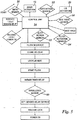
- FIG. 1 to 3 There is illustrated in Figures 1 to 3 a toilet unit 10 for use in a hospital.
- the toilet unit 10 is located in a room 12 off a hospital ward 14 and accessible by a door 16 beside which is a display 17 with one section 18 which indicates whether the room 12 is occupied (by a panel which is red to indicate when it is occupied and green when it is empty), and another section 19 with a "toilet" symbol selectively (i) green to indicate the toilet unit 10 is " available for use", and (ii) red to indicate it is "not presently available for use”.
- section 19 has a digital display of the number of seconds before the toilet unit 10 will be available for use.
- the toilet symbol is replaced with the International symbol for "Stop", a pictogram of a raised hand.
- a similar display 21 is provided on the wall within roorin 12 to indicate whether the toilet is available for use and, if isn't presently available, when it will be so.
- the unit When the toilet unit 10 is not in use but is ready for use, as shown in Figure 1 , the unit forms a sealed unit with a continuous smoothed exterior surface with no recesses, indents or protrusions which might otherwise harbour or retain dirt, grease, dust or waste materials. Such a surface allows quick and easy hygienic cleaning and maintenance of the unit.
- toilet unit 10 Upon entry to room 12, toilet unit 10 is in the mode as shown in Figure 2 .
- a motion sensor 22 detects their presence, sending a signal to control unit 24 of the toilet unit 10 to actuate lifting of toilet lid 26 to the position in Figure 3 . If the person requires toilet seat 28 to be raised, this is done by waving a hand in front of seat-raising sensor 30.
- seat 28 When seat 28 is in the lowered position, seat 28 lies on and sealingly engages with the upper surface 32 of the toilet bowl to provide a barrier against ingress therebetween of liquids, water droplets and miasma.
- lid 26 when lid 26 is in the lowered position (i.e. as shown in Figure 2 , lid 26 similarly sealingly engages with upper surface 32, with seat enclosed between lid 26 and upper surface 32.
- lid 26 and seat 28 When lid 26 and seat 28 are both in the raised position, they sealingly engage together once again to prevent liquid/droplet/miasma ingress. All these sealing engagements are achieved by completely sealing the gap between the seat and the toilet pan, and completely sealing the aperture in the seat with a "hubcap” moulding on the underside of the lid such that the seat is wholly contained within the lid with the lid being a hubcap-style moulding with an exact fit into the seat aperture, as seen in Figure 4 .
- ACTION PRODUCED BY Closing of lid/seat or lid (i) hand signal, or (ii) sensing departure of person; 2. Locking of lid sending closure of lid; 3. Start flushing operation sensing completion of locking of lid; 4. Initiate release delay sensing start of flushing operation. 5. Release lid expiry of set person of release delay" 6. Indicator shows that toilet is ready for next use sensing that lid is released.
- motion sensor 22 notes their absence and automatically starts the above appropriate sequence of actions.
- Each of upper surface 32 of the toilet bowl and lower surface 36 of seat 28 have enclosed embedded magneto-solenoid contacts or strips 38, 40 (see Figure 4 ) just below the surface of the respective component and electrically actuable by control unit 24 to sealingly lock seat 28 onto upper surface 32 as the first step of the flush sequence, likewise equivalent strips 42 embedded within the upper surface 38 of seat 28 are sealingly locked with strips 44 embedded within lower surface 46 of lid 26 (see Figure 3 ).
- part or all of the motorisation operations of toilet unit 10 are powered off such that the lid and seat are securely held in position in the sealed engagement of cistern, seat and lid against any forced movement until re-energisation.
- Control unit 24 senses when locking of seat 28 and lid 26 together on the cistern has been completed, whereupon the actual flushing in the cistern is begun, and simultaneously a delay timer 48 is initiated, set for a delay of 16 seconds being based on a flush duration of 8 seconds for a 4.5 litre flush and 8 further seconds for the miasma, generated by the flush, to subside completely. Accordingly, by the time that the lid is able to open again, there is effectively or actually no risk of any contaminated or infected liquid or vapour/gases exiting the cistern.
- an appropriate time delay would be a total of 20 seconds based on 12 seconds for the flush and 8 seconds for miasma settlement.
- toilet unit 10 has a turbulence sensor 50 and/or a sound sensor 52 within the toilet bowl to monitor for the end of the flush operation, and when control unit 24 detects that end, it starts another delay period being now for miasma settlement only, so 8 seconds.
- This variation can be used as an alternative, and/or in addition, to the basic form.
- the locking actions on the lid and/or seat, and/or the power-off of the appropriate part or all of toilet unit 10 are released or de-activated, and the indication on display 18 is appropriately changed.
- Toilet seat 28 is of U-shape with no forward central section bridging the two side arms, to inhibit the possibility of vandalism by application of moment forces against the hinge at the back of the seat.
- the 'timed delay' proposal of the present invention prevents the opening of the seat & lid until after the miasma has settled, and is dependent on the effective interaction of an electronic control, an auto-flushing device, a motorised seat/lid assembly and possibly the addition of a locking feature to provide further security against premature lifting of the lid by the user.
- An objective of 'elimination of dispersal risk' can be achieved with the described combination of an electronic control, an auto-flushing device, a motorised seat/lid assembly and possibly the addition of a locking feature.
- Figure 6 shows details of the display including the combination of the graphic symbols described.
- a long range sensor 102 detects a new occupant and lid 26 is raised, with an "UP” arrow 104 also being illuminated.
- the "UP” arrow 104 is illuminated when the seat/ lid 26 is about to or is going up or down - the “DOWN” arrow 105 is illuminated when the seat/lid 26 is about to or is going down.
- 'LIFT" and "LOWER” signs are illuminated separately as appropriate, so that the message is specific to the action required.
- the "WC graphic" 108 with the two position seat/lid 26 may be illuminated in white or in green according to operator choice.
- the "UP” and “DOWN” arrows 104, 105 are lit separately so that the image reflects what the WC is about to do.
- the Countdown display 110 starts when the lid has actually closed and the flush has just commenced.
- the short-range sensor 112 detects a hand wave to lift/lower the seat.
- the "UP” and “DOWN” arrows 104 and 105 also light.
- the Countdown display 110 shows a digital countdown from “9" to "0".
- the Countdown speed (and therefore overall time) may be varied depending on whether the flush is short or long, and also takes into account the settling period.
- the total Countdown sequence typically lasts 15 to 30 seconds (includes flush time) depending on the length of flush and the time required to allow the miasma to settle. The control will not allow the lid to be operated until the countdown is complete, minimising risk of airborne contamination from the WC.
- the "HAND” symbol has two positions 114, 116. When it flicks between the two positions, illuminated green, this indicates that the occupant should wave at the sensor if they wish to lift/lower the seat.
- the message 'TO LIFT-LOWER, SEAT WAVE HERE ⁇ ' 118 also flashes, pointing towards the short range sensor 112. Either the "UP” 104 or “DOWN” 105 arrows light to indicate what the WC is about to do.
- the upright “HAND” 116 symbol flashes in red light when the system requires the user to stop. This may be in response to the user forcing the lid or seat.
- the "HAND” symbol 116 is illuminated in red continuously with the 'OUT OF ORDER” sign 120 when the system detects a fault. If any sensor is activated (typically by a new user) then the "OUT OF ORDER" sign may flash to attract the attention of the new user.
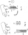
- FIGS 7A and 7B show a motorised hinge design being a 2-piece (or split) hinge construction in stainless steel, utilising 'top fixing' technology that can be used on both top and bottom fixing WC pans, the two parts being identical, and are not differently handed.
- a motorised hinge design being a 2-piece (or split) hinge construction in stainless steel, utilising 'top fixing' technology that can be used on both top and bottom fixing WC pans, the two parts being identical, and are not differently handed.
- FIGS 7A and 7B there is a slotted fixing head 120 and stud 122 with longitudinal slot 124 to accommodate cabling126, and motorised hinge pivot 128 (on seat 28 or lid 26) inside which (nit visible in the Figure) is a microdrive, with drive shaft 130 extending outwards.
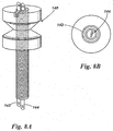
- FIG. 8A and 8B An alternative arrangement for cable management is the 'live' fixing as shown in Figures 8A and 8B , in which the 12v DC power is supplied through the fixing stud 140 itself.
- the fixing stud is designed rather like a 'phono' plug.
- the 2 part stud carries +ve and -ve DC power on separate insulated terminals 142, 144. This design is particularly suitable for bottom fixing.
- FIG. 9 An alternative arrangement for introducing a locking feature as shown in Figure 9 is a DC electro-magnet 150 embedded in the moulded lid 26 that interacts with a metal plate bonded to the WC pan front outer face, where the greatest force can be created when the electro-magnet is energised.
- a DC electro-magnet 150 embedded in the moulded lid 26 that interacts with a metal plate bonded to the WC pan front outer face, where the greatest force can be created when the electro-magnet is energised.
- leads 154 to an embedded, flat electro-magnet (moulded-in) to interact with a plate 156 bonded to WC pan.
- the electro-magnet 150 and the plate 156 are attracted creating a locking force.
- This idea is simple, and there are no moving parts. It can be activated for a short period during flush & settlement to lock the lid using minimum of electrical energy.
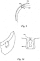
- a variant locking mechanism is a DC solenoid operable to move a locking pin 160.
- This pin can inter-lock directly with a suitable feature in the WC pan or it could work with an elastomeric expansion block 162 that would be forced out by the pin and 'wedge' with a suitable feature in the WC pan ( Figure 10 ).
- An advantage of the elastomeric block concept is that the whole device could be sealed by the elastomeric block 162 to prevent fluid ingress leading to corrosion, shorting etc.
- the solenoid-powered pin arrangement has a recess in the WC pan outer face, and an elastomer locking block - when the pin is pushed down by the solenoid, the elastomer block is pushed out into the pan recess.
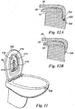
- UV sterilisation technology is to incorporate a high intensity UV lamp 170 into the toilet lid 26 (see Figure 11 ) with a reflector 172, a clear cover 174 sealed to rim 176 of lamp housing 178.
- UV sterilisation technology Another practical and cost-effective means of incorporating UV sterilisation technology into the system is to use low intensity (human safe), constant emission UV lamps as used in operating rooms (dual intensity), on wards, food prep & service areas etc. These lamps are standard mains powered and can be fitted as would normal lights with certain installation height and angle restrictions. Each cubicle may have a lamp mounted on the ceiling or back panel to provide UV sterilisation.
- the system may have a 'normally open' condition for the lid. This can be easily selected by a simple switch on the side of the control box. Then, with correct positioning of the overhead 'human safe' UV lamp it is possible to sterilise the seat top, the lid underside and most of the bowl. It is also possible to sterilise the rim by using this method, by programming the controller to alternate its 'normally open' condition to include 'seat up' condition so that the rim is exposed say every other use cycle. This arrangement compliments the use of anti-bacterial agents in the seat & lid components, the internal surfaces of which would receive little exposure to the steady UV source as the seat & lid are designed to remain closed when not in use.
- lid-rim design In an alternative lid-rim design, the opportunity for the user to open the lid while the flush-settle cycle is underway is reduced.
- Mechanical lock designs are possible but may be expensive to implement and may provide crevices to harbour micro-organisms.
- Two alternative designs for lid lip and rim are shown in Figures 12A and 12B .
- the first one ( Figure 12A ) requires that the ceramic WC pan profile is modified to provide a step 190 onto which the edge of the lid lip 192 can close. This could provide an alternative location for a seal 194 and greatly reduce the opportunity for the user to force open the lid.
- the lip 196 of the lid 26 is tapered and may even incorporate a finger seal and again reducing the opportunity for the user to force open the lid.
- the electronic control system operates to control, co-ordinate and provide DC power for lid & seat motors, flushing valve (short & long flush), and locking device. It also controls duration of flush/settle delay and all display functions.
- the control system determines whether short or long flush is required by the duration of use from sensor signals. A usage duration of greater than say 40 seconds determines that a long flush is required.
- the control will also enable the 'facilities manager' to select from several specific system start position options. For example, in a female facility it may be preferred to have a start condition where the seat & lid are lowered, whereas in a male facility it may be preferred to have a lid & seat up start condition. A third option would be to have lid up and seat down: In addition, it may be required to control the seat & lid position for sterilisation procedures as outlined above.
- a hard-wired, or wireless connection may be provided to enable data transmission.
- Valuable information on usage (number, frequency, water volume etc) and current condition (operational or shut down) can be transmitted to a remote facilities management terminal. This may allow facilities managers to make decisions and potentially even take direct action from the remote terminal. (e.g. shut-down a unit that has been used excessively; initiate a sterilisation sequence; advise maintenance staff by SMS text message to service units based on usage level or operational status). It is possible to automate such decisions at the device.
- the decision criteria can he programmed into the device controller and the same decisions made automatically by the controller, including sending out SMS text message to the mobile phone of the on duty maintenance personnel.
- a 'telecom transmitter' chip may be incorporated into the control board that may transmit data on facility use (such as time of usage, frequency, short & long flush etc). In future it may be even possible to provide in bowl 'analysis' and to transmit this data to a remote health worker.
Landscapes
- Health & Medical Sciences (AREA)
- Engineering & Computer Science (AREA)
- Public Health (AREA)
- Life Sciences & Earth Sciences (AREA)
- Hydrology & Water Resources (AREA)
- Water Supply & Treatment (AREA)
- Aviation & Aerospace Engineering (AREA)
- Toilet Supplies (AREA)
- Sanitary Device For Flush Toilet (AREA)
Applications Claiming Priority (2)
| Application Number | Priority Date | Filing Date | Title |
|---|---|---|---|
| GBGB0913464.4A GB0913464D0 (en) | 2009-08-03 | 2009-08-03 | Toilet |
| PCT/GB2010/051245 WO2011015848A1 (en) | 2009-08-03 | 2010-07-29 | Toilet |
Publications (2)
| Publication Number | Publication Date |
|---|---|
| EP2462289A1 EP2462289A1 (en) | 2012-06-13 |
| EP2462289B1 true EP2462289B1 (en) | 2016-08-17 |
Family
ID=41129511
Family Applications (1)
| Application Number | Title | Priority Date | Filing Date |
|---|---|---|---|
| EP10739685.5A Not-in-force EP2462289B1 (en) | 2009-08-03 | 2010-07-29 | Toilet |
Country Status (7)
| Country | Link |
|---|---|
| US (1) | US20120180208A1 (enExample) |
| EP (1) | EP2462289B1 (enExample) |
| JP (1) | JP5871278B2 (enExample) |
| AU (1) | AU2010280553A1 (enExample) |
| BR (1) | BR112012002437A2 (enExample) |
| GB (1) | GB0913464D0 (enExample) |
| WO (1) | WO2011015848A1 (enExample) |
Families Citing this family (19)
| Publication number | Priority date | Publication date | Assignee | Title |
|---|---|---|---|---|
| ITMI20130044A1 (it) * | 2013-01-15 | 2014-07-16 | Faringosi Hinges Srl | Cerniera |
| JP2014163163A (ja) * | 2013-02-26 | 2014-09-08 | Toto Ltd | トイレ装置 |
| JP2014189969A (ja) * | 2013-03-26 | 2014-10-06 | Toto Ltd | トイレ装置 |
| US20150074887A1 (en) * | 2013-11-19 | 2015-03-19 | Mark Allan Theuerl | Floor Sanitizer for Toilet Area |
| DE102015117357A1 (de) * | 2015-08-18 | 2017-02-23 | Hamberger Industriewerke Gmbh | WC-Sitzgelenkanordnung |
| KR102222432B1 (ko) * | 2016-05-13 | 2021-03-04 | 엘지전자 주식회사 | 정수기 |
| KR20190063060A (ko) * | 2017-11-29 | 2019-06-07 | 울산과학기술원 | 대소변 분리형 변기 및 이를 이용한 분뇨 처리 시스템 |
| CN111902067A (zh) * | 2018-03-30 | 2020-11-06 | 骊住株式会社 | 便器装置以及便座单元 |
| JP7213021B2 (ja) * | 2018-03-30 | 2023-01-26 | 株式会社Lixil | 便器装置 |
| TR201820199A2 (tr) * | 2018-12-24 | 2020-07-21 | Eczacibasi Yapi Gerecleri Sanayi Ve Ticaret Anonim Sirketi | Geri̇ bi̇ldi̇ri̇m sağlayan serami̇k sağlik gereci̇ ve geri̇ bi̇ldi̇ri̇m yöntemi̇ |
| TR201820196A2 (tr) * | 2018-12-24 | 2020-07-21 | Eczacibasi Yapi Gerecleri Sanayi Ve Ticaret Anonim Sirketi | Kullanici terci̇hleri̇ni̇ öğrenebi̇len serami̇k sağlik gereci̇ ve öğrenme yöntemi̇ |
| AU2020456269B2 (en) * | 2020-06-29 | 2025-03-27 | Ryan Hunt | Toilet sealing device |
| JP2022043490A (ja) * | 2020-09-04 | 2022-03-16 | パナソニックIpマネジメント株式会社 | 便器装置および便座装置 |
| JP7555016B2 (ja) * | 2020-10-27 | 2024-09-24 | パナソニックIpマネジメント株式会社 | 便器装置 |
| US20220408988A1 (en) * | 2021-06-28 | 2022-12-29 | Kohler Co. | Sealed toilet seat and lid |
| CN118488800A (zh) | 2021-11-15 | 2024-08-13 | 科琳娜股份有限公司 | 自提升坐便器座圈 |
| CA3238169A1 (en) | 2021-11-15 | 2023-05-19 | Mingyuan Li | Self-lifting toilet seat |
| US11950733B2 (en) | 2022-08-04 | 2024-04-09 | Cleana Inc. | Self-lowering toilet seat system |
| US20250017427A1 (en) * | 2023-04-25 | 2025-01-16 | Cleana Inc. | Electro-mechanical toilet seat system |
Family Cites Families (16)
| Publication number | Priority date | Publication date | Assignee | Title |
|---|---|---|---|---|
| US4253951A (en) * | 1978-11-09 | 1981-03-03 | The Procter & Gamble Company | Method of reducing aerosolization of wastewater |
| US5781942A (en) * | 1989-07-12 | 1998-07-21 | Sloan Valve Company | Wash stations and method of operation |
| CA2262747C (en) * | 1996-08-16 | 2007-05-15 | Cws International Ag | Triggering of a cleaning, ventilation, and or disinfection process |
| GB2324814B (en) * | 1997-05-02 | 2001-07-04 | Paul Walmsley | A cistern-less flushing toilet |
| EP1055782A1 (de) * | 1999-05-27 | 2000-11-29 | Cws International Ag | Verfahren und Vorrichtung zum Einführen von Reinigungs- und/oder Desinfektionsmittel in sanitären Anlagen |
| EP1648276A4 (en) | 2003-02-17 | 2008-05-07 | Glenn Michael Watt | MOTORIZED TOILET SEATING |
| US6895604B1 (en) * | 2003-05-19 | 2005-05-24 | Cris A. Ramsey | Self-contained exhaust fan for a water closet |
| JP4296843B2 (ja) * | 2003-05-27 | 2009-07-15 | パナソニック電工株式会社 | 水洗便器の洗浄水供給構造 |
| BRPI0503492A (pt) * | 2005-04-05 | 2006-11-28 | Jair Scherrer Leitao | sistema de descarga de vasos sanitários utilizando ar comprimido |
| JP4605113B2 (ja) * | 2006-07-20 | 2011-01-05 | パナソニック電工株式会社 | 便器 |
| JP2008025292A (ja) * | 2006-07-25 | 2008-02-07 | Matsushita Electric Works Ltd | 洋風便器装置 |
| JP2008050899A (ja) * | 2006-08-28 | 2008-03-06 | Matsushita Electric Works Ltd | 洋風便器装置 |
| JP5405729B2 (ja) * | 2007-03-12 | 2014-02-05 | パナソニック株式会社 | 便座装置 |
| JP2009063348A (ja) * | 2007-09-05 | 2009-03-26 | Toto Ltd | 自動装置 |
| DE102007060698B4 (de) * | 2007-12-12 | 2010-12-09 | Eberhard John | Selbstreinigende Toilette |
| WO2009131314A2 (ko) * | 2008-04-23 | 2009-10-29 | 웅진코웨이 주식회사 | 모터의 역기전력을 이용한 개폐수단의 제어장치 및 제어방법 |
-
2009
- 2009-08-03 GB GBGB0913464.4A patent/GB0913464D0/en not_active Ceased
-
2010
- 2010-07-29 US US13/388,413 patent/US20120180208A1/en not_active Abandoned
- 2010-07-29 EP EP10739685.5A patent/EP2462289B1/en not_active Not-in-force
- 2010-07-29 WO PCT/GB2010/051245 patent/WO2011015848A1/en not_active Ceased
- 2010-07-29 BR BR112012002437A patent/BR112012002437A2/pt not_active IP Right Cessation
- 2010-07-29 JP JP2012523385A patent/JP5871278B2/ja not_active Expired - Fee Related
- 2010-07-29 AU AU2010280553A patent/AU2010280553A1/en not_active Abandoned
Also Published As
| Publication number | Publication date |
|---|---|
| US20120180208A1 (en) | 2012-07-19 |
| WO2011015848A1 (en) | 2011-02-10 |
| BR112012002437A2 (pt) | 2019-09-24 |
| GB0913464D0 (en) | 2009-09-16 |
| JP5871278B2 (ja) | 2016-03-01 |
| JP2013501173A (ja) | 2013-01-10 |
| EP2462289A1 (en) | 2012-06-13 |
| AU2010280553A1 (en) | 2012-03-29 |
Similar Documents
| Publication | Publication Date | Title |
|---|---|---|
| EP2462289B1 (en) | Toilet | |
| EP3659919B1 (en) | Lavatory occupancy detection systems and methods | |
| KR100423949B1 (ko) | 비위생 물질 및/또는 오염 물질용 용기 | |
| US6202227B1 (en) | Automatic toilet flushing system | |
| ES2202779T3 (es) | Dispositivo de control del acceso a un recinto tal como un aseo. | |
| ES2669054T3 (es) | Dispositivo para la reducción de productos fibrosos | |
| KR102056317B1 (ko) | 공중화장실 변기의 자외선 살균장치 | |
| KR100765153B1 (ko) | 공중화장실의 통합적 관리장치 | |
| CN111760046A (zh) | 一种智能电梯消毒器控制系统及控制方法 | |
| CN210331194U (zh) | 一种电梯专用安全高效的消毒灭菌装置 | |
| US12320147B2 (en) | Manual and automatic disinfecting door system and method | |
| WO2006070281A2 (en) | Ultraviolet-ray ambient sterilising device particularly applicable to chambers used as toilets | |
| US20240390536A1 (en) | Intelligent, configurable, and connected operation of uv lamps in aircraft lavatory | |
| JPH11137881A (ja) | 光触媒によりセルフクリーニングを行なう洗濯機 | |
| CN212224108U (zh) | 一种隐形坐便器 | |
| KR20090025466A (ko) | 소변기 덮개 자동개폐장치 | |
| JPH11123299A (ja) | 光触媒によりセルフクリーニングを行なう洗濯機 | |
| KR102642465B1 (ko) | 하이브리드 IoT 양변기 살균장치 | |
| KR200294542Y1 (ko) | 건물의 비상문 개방제어장치 | |
| JPH05123272A (ja) | 便所の照明・換気方法 | |
| JP2002348925A (ja) | 排水圧送装置および排水圧送装置付便器 | |
| WO2023079535A1 (en) | An automatic hand disinfection dispenser, methods for use of the automatic hand disinfection dispenser and a distributed hand hygiene assistance system | |
| JPH1121028A (ja) | エレベータ制御装置 | |
| KR102405003B1 (ko) | 변기상태 모니터링부를 포함하는 스마트 변기 커버 | |
| CN216157269U (zh) | 一种基于自动门的具有杀菌和消毒功能的厕所 |
Legal Events
| Date | Code | Title | Description |
|---|---|---|---|
| PUAI | Public reference made under article 153(3) epc to a published international application that has entered the european phase |
Free format text: ORIGINAL CODE: 0009012 |
|
| 17P | Request for examination filed |
Effective date: 20120229 |
|
| AK | Designated contracting states |
Kind code of ref document: A1 Designated state(s): AL AT BE BG CH CY CZ DE DK EE ES FI FR GB GR HR HU IE IS IT LI LT LU LV MC MK MT NL NO PL PT RO SE SI SK SM TR |
|
| DAX | Request for extension of the european patent (deleted) | ||
| 17Q | First examination report despatched |
Effective date: 20151117 |
|
| GRAP | Despatch of communication of intention to grant a patent |
Free format text: ORIGINAL CODE: EPIDOSNIGR1 |
|
| INTG | Intention to grant announced |
Effective date: 20160310 |
|
| GRAS | Grant fee paid |
Free format text: ORIGINAL CODE: EPIDOSNIGR3 |
|
| GRAA | (expected) grant |
Free format text: ORIGINAL CODE: 0009210 |
|
| AK | Designated contracting states |
Kind code of ref document: B1 Designated state(s): AL AT BE BG CH CY CZ DE DK EE ES FI FR GB GR HR HU IE IS IT LI LT LU LV MC MK MT NL NO PL PT RO SE SI SK SM TR |
|
| REG | Reference to a national code |
Ref country code: GB Ref legal event code: FG4D |
|
| REG | Reference to a national code |
Ref country code: CH Ref legal event code: EP |
|
| REG | Reference to a national code |
Ref country code: IE Ref legal event code: FG4D |
|
| REG | Reference to a national code |
Ref country code: AT Ref legal event code: REF Ref document number: 821241 Country of ref document: AT Kind code of ref document: T Effective date: 20160915 |
|
| REG | Reference to a national code |
Ref country code: DE Ref legal event code: R096 Ref document number: 602010035613 Country of ref document: DE |
|
| REG | Reference to a national code |
Ref country code: NL Ref legal event code: MP Effective date: 20160817 |
|
| REG | Reference to a national code |
Ref country code: LT Ref legal event code: MG4D |
|
| REG | Reference to a national code |
Ref country code: AT Ref legal event code: MK05 Ref document number: 821241 Country of ref document: AT Kind code of ref document: T Effective date: 20160817 |
|
| PG25 | Lapsed in a contracting state [announced via postgrant information from national office to epo] |
Ref country code: NO Free format text: LAPSE BECAUSE OF FAILURE TO SUBMIT A TRANSLATION OF THE DESCRIPTION OR TO PAY THE FEE WITHIN THE PRESCRIBED TIME-LIMIT Effective date: 20161117 Ref country code: HR Free format text: LAPSE BECAUSE OF FAILURE TO SUBMIT A TRANSLATION OF THE DESCRIPTION OR TO PAY THE FEE WITHIN THE PRESCRIBED TIME-LIMIT Effective date: 20160817 Ref country code: LT Free format text: LAPSE BECAUSE OF FAILURE TO SUBMIT A TRANSLATION OF THE DESCRIPTION OR TO PAY THE FEE WITHIN THE PRESCRIBED TIME-LIMIT Effective date: 20160817 Ref country code: FI Free format text: LAPSE BECAUSE OF FAILURE TO SUBMIT A TRANSLATION OF THE DESCRIPTION OR TO PAY THE FEE WITHIN THE PRESCRIBED TIME-LIMIT Effective date: 20160817 Ref country code: NL Free format text: LAPSE BECAUSE OF FAILURE TO SUBMIT A TRANSLATION OF THE DESCRIPTION OR TO PAY THE FEE WITHIN THE PRESCRIBED TIME-LIMIT Effective date: 20160817 Ref country code: IT Free format text: LAPSE BECAUSE OF FAILURE TO SUBMIT A TRANSLATION OF THE DESCRIPTION OR TO PAY THE FEE WITHIN THE PRESCRIBED TIME-LIMIT Effective date: 20160817 |
|
| PG25 | Lapsed in a contracting state [announced via postgrant information from national office to epo] |
Ref country code: PL Free format text: LAPSE BECAUSE OF FAILURE TO SUBMIT A TRANSLATION OF THE DESCRIPTION OR TO PAY THE FEE WITHIN THE PRESCRIBED TIME-LIMIT Effective date: 20160817 Ref country code: SE Free format text: LAPSE BECAUSE OF FAILURE TO SUBMIT A TRANSLATION OF THE DESCRIPTION OR TO PAY THE FEE WITHIN THE PRESCRIBED TIME-LIMIT Effective date: 20160817 Ref country code: LV Free format text: LAPSE BECAUSE OF FAILURE TO SUBMIT A TRANSLATION OF THE DESCRIPTION OR TO PAY THE FEE WITHIN THE PRESCRIBED TIME-LIMIT Effective date: 20160817 Ref country code: AT Free format text: LAPSE BECAUSE OF FAILURE TO SUBMIT A TRANSLATION OF THE DESCRIPTION OR TO PAY THE FEE WITHIN THE PRESCRIBED TIME-LIMIT Effective date: 20160817 Ref country code: PT Free format text: LAPSE BECAUSE OF FAILURE TO SUBMIT A TRANSLATION OF THE DESCRIPTION OR TO PAY THE FEE WITHIN THE PRESCRIBED TIME-LIMIT Effective date: 20161219 Ref country code: GR Free format text: LAPSE BECAUSE OF FAILURE TO SUBMIT A TRANSLATION OF THE DESCRIPTION OR TO PAY THE FEE WITHIN THE PRESCRIBED TIME-LIMIT Effective date: 20161118 Ref country code: ES Free format text: LAPSE BECAUSE OF FAILURE TO SUBMIT A TRANSLATION OF THE DESCRIPTION OR TO PAY THE FEE WITHIN THE PRESCRIBED TIME-LIMIT Effective date: 20160817 |
|
| PG25 | Lapsed in a contracting state [announced via postgrant information from national office to epo] |
Ref country code: RO Free format text: LAPSE BECAUSE OF FAILURE TO SUBMIT A TRANSLATION OF THE DESCRIPTION OR TO PAY THE FEE WITHIN THE PRESCRIBED TIME-LIMIT Effective date: 20160817 Ref country code: EE Free format text: LAPSE BECAUSE OF FAILURE TO SUBMIT A TRANSLATION OF THE DESCRIPTION OR TO PAY THE FEE WITHIN THE PRESCRIBED TIME-LIMIT Effective date: 20160817 |
|
| REG | Reference to a national code |
Ref country code: DE Ref legal event code: R097 Ref document number: 602010035613 Country of ref document: DE |
|
| PG25 | Lapsed in a contracting state [announced via postgrant information from national office to epo] |
Ref country code: CZ Free format text: LAPSE BECAUSE OF FAILURE TO SUBMIT A TRANSLATION OF THE DESCRIPTION OR TO PAY THE FEE WITHIN THE PRESCRIBED TIME-LIMIT Effective date: 20160817 Ref country code: SM Free format text: LAPSE BECAUSE OF FAILURE TO SUBMIT A TRANSLATION OF THE DESCRIPTION OR TO PAY THE FEE WITHIN THE PRESCRIBED TIME-LIMIT Effective date: 20160817 Ref country code: BG Free format text: LAPSE BECAUSE OF FAILURE TO SUBMIT A TRANSLATION OF THE DESCRIPTION OR TO PAY THE FEE WITHIN THE PRESCRIBED TIME-LIMIT Effective date: 20161117 Ref country code: SK Free format text: LAPSE BECAUSE OF FAILURE TO SUBMIT A TRANSLATION OF THE DESCRIPTION OR TO PAY THE FEE WITHIN THE PRESCRIBED TIME-LIMIT Effective date: 20160817 Ref country code: BE Free format text: LAPSE BECAUSE OF FAILURE TO SUBMIT A TRANSLATION OF THE DESCRIPTION OR TO PAY THE FEE WITHIN THE PRESCRIBED TIME-LIMIT Effective date: 20160817 Ref country code: DK Free format text: LAPSE BECAUSE OF FAILURE TO SUBMIT A TRANSLATION OF THE DESCRIPTION OR TO PAY THE FEE WITHIN THE PRESCRIBED TIME-LIMIT Effective date: 20160817 |
|
| PLBE | No opposition filed within time limit |
Free format text: ORIGINAL CODE: 0009261 |
|
| STAA | Information on the status of an ep patent application or granted ep patent |
Free format text: STATUS: NO OPPOSITION FILED WITHIN TIME LIMIT |
|
| REG | Reference to a national code |
Ref country code: FR Ref legal event code: PLFP Year of fee payment: 8 |
|
| 26N | No opposition filed |
Effective date: 20170518 |
|
| PG25 | Lapsed in a contracting state [announced via postgrant information from national office to epo] |
Ref country code: SI Free format text: LAPSE BECAUSE OF FAILURE TO SUBMIT A TRANSLATION OF THE DESCRIPTION OR TO PAY THE FEE WITHIN THE PRESCRIBED TIME-LIMIT Effective date: 20160817 |
|
| REG | Reference to a national code |
Ref country code: CH Ref legal event code: PL |
|
| PG25 | Lapsed in a contracting state [announced via postgrant information from national office to epo] |
Ref country code: CH Free format text: LAPSE BECAUSE OF NON-PAYMENT OF DUE FEES Effective date: 20170731 Ref country code: LI Free format text: LAPSE BECAUSE OF NON-PAYMENT OF DUE FEES Effective date: 20170731 |
|
| REG | Reference to a national code |
Ref country code: IE Ref legal event code: MM4A |
|
| PG25 | Lapsed in a contracting state [announced via postgrant information from national office to epo] |
Ref country code: LU Free format text: LAPSE BECAUSE OF NON-PAYMENT OF DUE FEES Effective date: 20170729 |
|
| REG | Reference to a national code |
Ref country code: FR Ref legal event code: PLFP Year of fee payment: 9 |
|
| PG25 | Lapsed in a contracting state [announced via postgrant information from national office to epo] |
Ref country code: IE Free format text: LAPSE BECAUSE OF NON-PAYMENT OF DUE FEES Effective date: 20170729 |
|
| PG25 | Lapsed in a contracting state [announced via postgrant information from national office to epo] |
Ref country code: MT Free format text: LAPSE BECAUSE OF NON-PAYMENT OF DUE FEES Effective date: 20170729 |
|
| PG25 | Lapsed in a contracting state [announced via postgrant information from national office to epo] |
Ref country code: AL Free format text: LAPSE BECAUSE OF FAILURE TO SUBMIT A TRANSLATION OF THE DESCRIPTION OR TO PAY THE FEE WITHIN THE PRESCRIBED TIME-LIMIT Effective date: 20160817 |
|
| PGFP | Annual fee paid to national office [announced via postgrant information from national office to epo] |
Ref country code: FR Payment date: 20180726 Year of fee payment: 9 Ref country code: DE Payment date: 20180802 Year of fee payment: 9 |
|
| PGFP | Annual fee paid to national office [announced via postgrant information from national office to epo] |
Ref country code: GB Payment date: 20180726 Year of fee payment: 9 |
|
| PG25 | Lapsed in a contracting state [announced via postgrant information from national office to epo] |
Ref country code: HU Free format text: LAPSE BECAUSE OF FAILURE TO SUBMIT A TRANSLATION OF THE DESCRIPTION OR TO PAY THE FEE WITHIN THE PRESCRIBED TIME-LIMIT; INVALID AB INITIO Effective date: 20100729 Ref country code: MC Free format text: LAPSE BECAUSE OF FAILURE TO SUBMIT A TRANSLATION OF THE DESCRIPTION OR TO PAY THE FEE WITHIN THE PRESCRIBED TIME-LIMIT Effective date: 20160817 |
|
| PG25 | Lapsed in a contracting state [announced via postgrant information from national office to epo] |
Ref country code: CY Free format text: LAPSE BECAUSE OF NON-PAYMENT OF DUE FEES Effective date: 20160817 |
|
| PG25 | Lapsed in a contracting state [announced via postgrant information from national office to epo] |
Ref country code: MK Free format text: LAPSE BECAUSE OF FAILURE TO SUBMIT A TRANSLATION OF THE DESCRIPTION OR TO PAY THE FEE WITHIN THE PRESCRIBED TIME-LIMIT Effective date: 20160817 |
|
| REG | Reference to a national code |
Ref country code: DE Ref legal event code: R119 Ref document number: 602010035613 Country of ref document: DE |
|
| GBPC | Gb: european patent ceased through non-payment of renewal fee |
Effective date: 20190729 |
|
| PG25 | Lapsed in a contracting state [announced via postgrant information from national office to epo] |
Ref country code: TR Free format text: LAPSE BECAUSE OF FAILURE TO SUBMIT A TRANSLATION OF THE DESCRIPTION OR TO PAY THE FEE WITHIN THE PRESCRIBED TIME-LIMIT Effective date: 20160817 |
|
| PG25 | Lapsed in a contracting state [announced via postgrant information from national office to epo] |
Ref country code: DE Free format text: LAPSE BECAUSE OF NON-PAYMENT OF DUE FEES Effective date: 20200201 Ref country code: GB Free format text: LAPSE BECAUSE OF NON-PAYMENT OF DUE FEES Effective date: 20190729 |
|
| PG25 | Lapsed in a contracting state [announced via postgrant information from national office to epo] |
Ref country code: FR Free format text: LAPSE BECAUSE OF NON-PAYMENT OF DUE FEES Effective date: 20190731 |
|
| PG25 | Lapsed in a contracting state [announced via postgrant information from national office to epo] |
Ref country code: IS Free format text: LAPSE BECAUSE OF FAILURE TO SUBMIT A TRANSLATION OF THE DESCRIPTION OR TO PAY THE FEE WITHIN THE PRESCRIBED TIME-LIMIT Effective date: 20161217 |