EP2462015B1 - Verfahren und steuerung zur kalibrierung einer automatisch lenkenden einparkhilfe - Google Patents
Verfahren und steuerung zur kalibrierung einer automatisch lenkenden einparkhilfe Download PDFInfo
- Publication number
- EP2462015B1 EP2462015B1 EP10739615.2A EP10739615A EP2462015B1 EP 2462015 B1 EP2462015 B1 EP 2462015B1 EP 10739615 A EP10739615 A EP 10739615A EP 2462015 B1 EP2462015 B1 EP 2462015B1
- Authority
- EP
- European Patent Office
- Prior art keywords
- actual
- maximum
- steering
- parking
- path profile
- Prior art date
- Legal status (The legal status is an assumption and is not a legal conclusion. Google has not performed a legal analysis and makes no representation as to the accuracy of the status listed.)
- Active
Links
Images
Classifications
-
- B—PERFORMING OPERATIONS; TRANSPORTING
- B62—LAND VEHICLES FOR TRAVELLING OTHERWISE THAN ON RAILS
- B62D—MOTOR VEHICLES; TRAILERS
- B62D15/00—Steering not otherwise provided for
- B62D15/02—Steering position indicators ; Steering position determination; Steering aids
- B62D15/027—Parking aids, e.g. instruction means
- B62D15/0285—Parking performed automatically
Definitions
- the invention relates to (semi-) automatic parking assistants, which support the parking in a parking space by automatic steering.
- Such parking systems have sensors to detect a parking space when driving past, and to retract as optimally as possible in the subsequent parking in the parking space in the subsequent parking.
- the steering wheel is automatically guided, wherein during the reverse driving an actuator operates the steering wheel, wherein the actuator is connected to a controller that provides the calculated optimum steering angle and thus the parking path.
- the predetermined parking path that is, the desired parking path and thus the (instantaneous) Einlenkwinkel of the actuator and the steering gear is accurately executed.
- This is achieved in the prior art, for example, characterized in that the corresponding steering components are dimensioned according to the load and a high steering torque provides for compliance with the steering specification.
- From the EP 0 872 402 A3 is a method for automatically steering a vehicle is known in which an actual steering angle is detected and compared with a desired steering angle. Depending on the thus determined deviation between the desired and the actual steering angle, a corrected desired steering angle is determined, so that the vehicle can reach a fixed end position.
- the concept underlying the invention is to provide the Einlenkwinkel not by a control method in which it is assumed that a specification is strictly adhered to, but provided by a control method that can take into account an error occurring during steering, so that the error at least partially compensated.
- this can provide parking systems, in which at a strong deflection, a more or less strong steering error occurs, whereby a precise steering of the vehicle when parking is possible even with faulty systems.
- the method provides to calculate a desired parking path (which is likewise calculated in the prior art and used in the prior art directly for driving an actuator), and to detect an actual trajectory in order to detect an error by comparison , which is compensated according to the invention.
- the compensation may be provided by correcting the drive commands provided by the actuator or by calibration, for example according to a corrected drive characteristic.
- a corrected drive characteristic In contrast to the prior art, it is not assumed that the target parking path is executed by the system as intended, but it is detected for control and subsequent regulation, an actual trajectory to perform comparisons can. This actual trajectory is compared with the desired trajectory to determine an error. This error, in turn, is used in the application of corrective measures, particularly when constructing a correction parameter (which may numerically substantially or directly correspond to the error), the steering angle being given to the controller according to a combination of the adjustment angle and the correction parameter (the the error is reflected) is provided.
- Correction parameter is also referred to as a drive characteristic which is created according to detected errors.
- the steering system according to the invention is driven according to a combination of this (set) setting angle and the correction parameter.
- the consideration of a previously detected correction parameter or consideration of the detected error between actual and desired trajectory allows precise parking according to the desired parking path even with faulty steering systems, since their control is accompanied by using the correction parameter with an error compensation.
- the consideration of the correction parameter which reflects the detected error, can be designated and provided as a regulation as well as a calibration, the calibration being that the controlling system is still driven by the desired trajectory, but this trajectory according to the correction parameter executes and forwards it to the appropriate actuator.
- the correction of such a control system corresponds to a calibration, wherein the calibration according to the invention is based on the comparison of an actual trajectory with a desired trajectory.
- the control approach according to the invention is provided by detecting an error between the desired trajectory and the actual trajectory and taking this error into account in the control.
- the regulation according to the invention differs from the calibration according to the invention in that the error in the control is detected continuously during the control, and the error is first detected during the calibration in order to be used for future control processes, however, both aspects of the invention Implemented concept, according to which an error between target and actual trajectory is detected and during parking this error is taken into account during the control. Due to this, according to the invention, the term calibration and the term control relate to the same concept, namely the detection of an error between actual and desired course and the consideration of this error in the control. Therefore, the term calibration will not hereafter be distinguished from the term control, unless stated otherwise.
- the inventive method for calibrating a parking aid therefore relates to a parking aid that is set up to actively control a Einlenkwinkels a vehicle.
- electromechanical actuators are referred to, which are connected to the steering system of a vehicle.
- motor vehicles such as passenger cars or trucks in which one axis (or both axes) are limited in order to determine the direction of the vehicle by steering.
- Electro-hydraulic or electropneumatic force transducers are also suitable as actuators.
- the control is preferably provided electronically, but in principle also pneumatic or hydraulic controls are conceivable. In the latter implementation possibilities, however, converters must be provided to convert electrical sensor signals into corresponding physical pressure magnitudes.
- the inventive method provides to detect a parking space by means of sensors automatically, that is by driving past the parking space, the sensors are preferably directed to the side of the vehicle to detect other (parking) vehicles or corresponding obstacles.
- the sensors may be, for example, ultrasonic or radar sensors.
- a desired trajectory is calculated on the basis of the thus detected parking space.
- This calculation also includes a profile of the Einlenkwinkels along the trajectory.
- the trajectory can be approximated by straight lines, circular sections and clothoids, the individual sections of the trajectory corresponding to a certain course of the Einlenkwinkels.
- the trajectory corresponds to the integral of the corresponding course of the Einlenkwinkels.
- circular sections result from a constant steering angle, the magnitude of which is not zero
- straight lines result from a constant steering angle of zero
- clothoids result from a linear increase or linear decrease in the steering angle along the path.
- the invention further provides to provide the course of the Einlenkwinkels or the target trajectory thus obtained by driving a controllable actuator.
- the controllable actuator is, for example, an electromechanical actuator as described above, which receives digital or analog signals representing the desired steering angle to be controlled, the actuator generating a corresponding motion, torque or force around the steering system of the vehicle in accordance with the intended steering angle to use.
- the method further comprises the steps of detecting an actual trajectory, which results from the control according to target trajectory or to be controlled Einlenkwinkel.
- the actual trajectory can be provided by an entire trajectory represented by geometrical data, can be subdivided into sections in which the steering angle to be controlled has a specific, precisely defined course (for example, sections with constant angle, constant angle equal to zero or linearly increasing / falling angle).
- the actual trajectory can also be detected by the detection of the actual, prevailing in the steering system of the vehicle Einlenkwinkels, since this is clearly linked to the actual trajectory.
- a direction or an actual Einlenkwinkel can further be provided, which corresponds to a maximum, to be controlled Einlenkwinkel.
- the actual trajectory can be detected by repeatedly detecting a lateral distance after the vehicle is retracted into the parking space.
- the detection of the actual trajectory is provided by detecting the maximum present in the steering system of the vehicle Einlenkwinkels, this corresponds to a maximum, controlled Einlenkwinkel.
- this actual trajectory (which can also be provided only as an angle) with the desired trajectory (which may be provided only as a default Einlenkwinkel), compared, and the resulting from the comparison error is determined.
- the comparison can be provided as a difference between a steering angle to be controlled and the actual steering angle present in the steering system (target-actual comparison), the error corresponding to the difference.
- the error is provided in particular as a value which corresponds to the difference value formed.
- a correction parameter is created, which is equated to the error in a particularly simple embodiment.
- the created correction parameter is linked to the error via a monotone function.
- the monotone function may be a monotonic or strictly monotonic function, for example a linear or directly proportional function, where the monotonic function may be a monotonically increasing or a monotonically decreasing function.
- the function is selected as an increasing or decreasing function, depending on how the resulting correction parameter is taken into account during control.
- the combination of the setting angle with the correction parameter and the creation of the correction parameter result in at least partial compensation of the error in the controller.
- the Einlenkwinkel is combined according to the inventive method with the correction parameter, for example by addition (or by subtraction, depending on whether the function is increasing or decreasing), the drive quantity of this combination corresponds.
- the control is thus based not only on a predetermined setting angle, but also on a thus to be combined before the activation of the actuator correction parameter, which reflects the conversion between the actuated setting angle and actually generated setting angle.
- the actual trajectory is detected by detecting an actual adjustment angle based on the position of a steering wheel, a steering linkage, the actuator or another component of the steering system.
- the actual adjustment angle can be detected in particular by an angle sensor which is connected to the corresponding component.
- the direct detection of the actual adjustment angle can also be provided by evaluating a trajectory. If, according to this aspect of the invention, the actual trajectory is detected by the actual setting angle, the result is a relatively simple calculation, since the actual setting angle is merely a single numerical date, which accordingly requires a small amount of computation.
- the angular position can be detected by an angle sensor or angle sensor at each point of the steering system, which moves when steering.
- the actual trajectory is detected not only on the basis of a single angular information but on the basis of an overall locus, preferably in the form of a locus, which represents the movement of the vehicle.
- the locus may also represent the movement of the vehicle part or the movement of a sensor or a sensor device which is mounted on the vehicle.
- the trajectory can be detected by any vehicle component that is connected to the vehicle.
- the actual trajectory can be detected by repeated, continuous or continued sensor detection, wherein the sensor preferably detects the distance or a relative position of the vehicle to an outside object.
- controlling the Einlenkwinkels comprises driving the actuator with a desired Maximaleinschwert.
- Capturing the Actual trajectory comprises: detecting an actual maximum Einlenkhongs, which results from the driving with the desired maximum Einlenkwert.
- a target Maximaleinlenkwert is specified, and it is determined by means of an actual Maximaleinlenkwerts whether the steering fully follows the Soll Maximaleinlenkwert or accurately, or if there is a smaller actual maximum Einlenkwert than the planned Maximaleinlenkwert, the would result from driving the desired Maximaleinlenkwerts at an optimal system.
- a desired maximum steering value is used as a target input point, and whether the system fully follows the target maximum steering value or whether the system can not follow the target maximum steering value due to errors by comparison with the actually executed maximum steering angle.
- the error results from the difference between the desired maximum insertion value and the actual maximum insertion value.
- the difference is preferably applied with a sign that takes into account the steering direction.
- the difference may be formed by the difference between the magnitude of the desired maximum steering value and the magnitude of the actual maximum steering value.
- the error is determined by presetting a maximum Einlenkwerts and by observing the reaction by the steering system.
- the actual Maximaleinschwert can be detected here by determining the position of the steering wheel, the steering linkage, the actuator or other component of the steering system of the vehicle. In this case, the determination of the actual, converted actual maximum insertion value is based on the detection of an angle by means of an angle sensor.
- the actual Maximaleinschwert can also be determined due to the maximum curvature of the detected actual trajectory. In this case, the maximum curvature of a section of the locus curve is determined, this section resulting in a result of the setpoint maximum steering value.
- the locus corresponds to the actual trajectory, which reflects the movement of the vehicle.
- the actual trajectory is thus the locus of a component that is attached to the vehicle, such as a sensor with which the parking space is detected.
- the actual maximum steering value is thus determined by the consideration of the course of movement of the vehicle.
- a first parking step is carried out, and immediately or indirectly thereafter following a second parking step, wherein in both Einpark suitsen different maximum Einlenkwinkel be used.
- the maximum Einlenkwinkel is at the second parking step (in general: the manipulated variable) greater than the first parking step, so as to successively determine the limits of the steering system.
- the limits of the steering system in this case control parameters are referred to, in which an increase in the deflection leads to significant errors. This is the case, for example, when an operating limit, for example the deflection limit, a maximum angular position of the actuator or a maximum torque of the actuator is achieved. At this point begins an area of oversteer, which manifests itself in that a further additional increase of the drive signal is implemented only incompletely.
- the method comprises carrying out a second parking step by driving with a maximum steering angle, which is increased compared to the first parking step by a drive increment.
- the maximum actual curvatures of the respective resulting actual trajectory are compared with each other to detect whether the drive increment is completely or only partially implemented by the steering system.
- this angle is preferably stored and future setpoint trajectories are designed such that they have a maximum curvature which is not above the detected maximum actual Curvature (or the associated Einlenkwinkel) is located.
- detected maximum deflection angles are temporarily stored so that they can be taken into account during the following parking steps.
- the embodiment thus described is based on provoking an error in which the maximum steering angle is increased to an inaccuracy limit, up to which the system can follow the given angle but produces large inaccuracies after the maximum steering angle.
- the correction parameter then exists in a value that predetermines a cap so that no deflection angle greater than the maximum deflection angle thus obtained is used for the following desired path characteristics. This cap can also be used to create / modify a drive characteristic.
- the drive increment is increasingly increased with each parking step, and the maximum actual curvature resulting from each parking step is concretely recorded.
- the respective maximum actual curvatures of the parking steps are compared with each other.
- the increase of the associated maximum actual curvatures of successive parking steps is detected here.
- the correction parameter then results by detecting a decrease or absence of the increase in the comparison of maximum actual curvatures of successive steps. For example, if the maximum steering angle is regularly increased by one drive increment, then a decrease or an absence of the increase can be recognized by a flattening of the increase in the maximum actual turns.
- the correction parameter indicates a cap of the controllable Einlenkwinkels. This corresponds to a calibration whereby calibrated target trajectories generated thereafter are calibrated and thus have no maximum curvature equal to or greater than the maximum actual curvature.
- the steering angle can also be increased successively during one and the same parking step.
- the resulting actual trajectory is detected (either by detecting the locus along which the vehicle is moving, or by determining the position of the steering wheel, the steering linkage, the actuator or other steering system component), and the associated (current) controlled Einlenkwinkel (according to the desired trajectory) is detected. If the situation arises that although the Einlenkwinkel continues to increase, but the actual trajectory or the position of the steering system component no longer (fully) follows this increasing Einlenkwinkel, then the controlled Einlenkwinkel or the position of the steering wheel can be determined from the an increase in the Einlenkwinkels no longer has the desired increase in the position of the steering wheel result.
- the curvature is increased continuously or in particular stepwise, that is to say incrementally.
- the increase in the curvature of the resulting actual trajectory or the increase in the angular position of a longitudinal system component is detected and it is determined by comparison whether the system is currently operating in a fault-free control range or already working in a faulty control range.
- increasing curvature or increasing Einlenkwinkel means an increasing strength of Einlenkens, regardless of the sign or the Einlenkiques, so that these terms are synonymous with the amount of curvature or with the amount of Einlenkwinkels.
- the Einlenkwinkel is detected, in which the increase of the curvature (the amount of curvature) of the actual trajectory or the position of the longitudinal system component is less than the increase in the curvature of the desired trajectory or less than the increase of the controlled Einlenkwinkels.
- the correction parameter is then provided with a value corresponding to this curvature or position or the corresponding Einlenkwinkel, wherein the correction parameter is set to a value corresponding to the Einlenkwinkel less increase.
- the detection of the smaller increase (the Einlenkwinkels) is equivalent to the detection of a region in which the control system is no longer linear or error-prone to the desired trajectory or to be addressed Einlenkwinkel.
- the corresponding correction parameter is stored and provided in the following as a cap for the desired trajectory, so that in a further parking step controlling the Einlenkwinkels according to this cap does not exceed this.
- the desired trajectory of the following parking steps is provided such that its maximum curvature (in terms of amount) is not greater than this cap.
- a (predetermined) threshold value can be provided, which is compared with the amount of deviation and leads only from a predetermined error amount threshold or difference for detecting the correction parameter.
- This can be realized, for example, by means of a comparator and a predetermined threshold value, the comparator comparing the threshold value with the deviation between the nominal and actual values and, when the threshold value is exceeded, causing the system according to the invention to increase the associated deflection angle or the associated desired curvature to save.
- This stored value corresponds to a calibration value which is used in subsequent parking maneuvers in order to avoid that the steering angle to be controlled is within a range in which the control is faulty.
- the method thus described calibrates a control according to a standard interval in which the steering angles to be controlled are permitted and a limit beyond which the amounts of the steering angle lead to a faulty implementation.
- a linear error can also be detected and used for calibration, wherein the steering angle to be controlled is increased and the associated conversion by detecting the actual trajectory as described above this is compared. If it is thus recognized that the conversion is not completely provided and that the actual angular increase differs from the desired angular increase, then the quotient of desired and actual angular increase can be formed. This quotient is used for calibration in further control and parking steps, for example, to multiply the steering angle to be controlled with the reciprocal of the quotient before the set Einlenkwinkel is used for driving. As a result, errors can be compensated, which increase linearly or directly proportional to increasing Einlenkwinkel.
- the invention is further realized by a controller which is used to carry out the method described above.
- the controller includes an input for detecting physical environmental characteristics (for detecting the parking space) and for detecting the actual trajectory or the change in direction, which results from the control.
- the controller further comprises an output to drive an actuator in accordance with the Einlenk angle to be controlled.
- a calculation unit of the controller is connected to the input and the output and calculates the desired trajectory based on the environmental characteristics. Furthermore, this calculation unit takes into account the correction parameter in which the desired trajectory is provided, for example, with a maximum curvature which is below a Einlenkwinkel, from which the actual trajectory only erroneously follows the controlled Einlenkwinkel.
- the controller further includes a comparator to detect this error.
- the comparator is set up to compare the actual trajectory with the desired trajectory, wherein the comparator can also determine a possible error.
- the controller further comprises a correction device that performs the above-described consideration of the correction parameter.
- the correction device is set up to generate the correction parameters as a function of the error and is set up to correct the desired parking path, the steering angle to be controlled or both.
- the correction device combines the desired trajectory or the Einlenkwinkel to be set with the correction parameter.
- the combination which is provided by the correction device, comprises the capping of a target trajectory to be created according to the maximum Einlenkwinkel, from which the steering system only erroneously follows the target specifications.
- the controller further comprises an angle sensor, which can be mechanically connected to a steering system component.
- This steering system component can be used as a steering wheel, steering linkage or be provided as an actuator that actuates the steering.
- the angle sensor detects the angular position of the respective vehicle component, which may also be the chassis of the vehicle, wherein the angle encoder is also connected to the input to deliver these angle signals that represent the detected angle.
- the controller further comprises an incrementing device to increase a drive increment or the to be controlled Einlenkwinkel, preferably gradually with a constant step height.
- the associated, resulting maximum curvature of the resulting actual trajectory is recorded and evaluated.
- the controller evaluates whether the increase in the drive increment leads to a maximum curvature of the actual trajectory.
- the controller detects whether the increase in the drive increment corresponds to the increase in the curvature of the actual trajectory, or whether the increase in the drive increment is smaller than the maximum curvature of the actual trajectory.
- the controller detects whether the increase in the drive increment results in a maximum curvature of the actual trajectory that is less than a predefined threshold value compared to a maximum curvature that resulted before the increase of the An Kunststoffinscrement.
- the deviation between the setpoint and the actual angle is detected by the control on the basis of a predefined threshold value as the drive increment increases.
- a comparator compares the threshold with the difference between the respective increases of the desired and actual values. Exceeding the threshold value here means that the actual angle does not follow the target angle without errors and thus the controller is located in an area in which the target specification is not correctly converted. If the threshold is exceeded, the controlled Einlenkwinkel or the curvature of the actual trajectory is stored as the basis for calibration.
- the calibration basis may be stored in a memory of the system, with the constraint of the system being connected to this memory to take into account the calibration when creating the desired trajectory or in controlling the Einlenkellwinkels to be set.
- the device according to the invention can be implemented by means of a microcontroller and associated software or associated software elements, wherein the software or the software elements implement individual or multiple components of the controller.
- quiescent circuits whose function is predetermined by their circuitry may also be used.
- the comparator may be provided by a hardware comparator circuit.
- the input and the output can be provided both as digital and as analog signal interfaces, wherein when using analog signals the input or the output preferably comprises an A / D or a D / A converter.
- the maximum setpoint steering angle can first be increased by one increment for several successive parking processes for each successive parking process until the maximum possible steering angle is detected, from which the steering system is no longer or only faulty follows the target Einlenkwinkel.
- the calibration according to the invention is then used as a monitoring measure, which optionally intervenes in the control.
- the execution of the desired trajectory can be monitored in further Einpark methodologiesen by detection according to the invention the desired trajectory with the actual trajectory, in order to redetermine the maximum possible parking angle in case of errors occurring during the further parking processes (as described above) in order to then consider this for still following parking processes as described above.
- the same sensors distance sensor, angle sensor
- the maximum possible steering angle detection process can be repeated to accommodate changes in road / tire conditions.
- the maximum possible Einlenkwinkel is redetermined and may be smaller than the previous maximum possible Einlenkwinkel, bsp. when frictional forces in the steering system have increased, or may be greater than the previous maximum possible steering angle when friction forces have been reduced, as is the case when changing from winter tires to summer tires.
- the control according to the invention has an input with which inspections or tire changes can be detected, eg. an interface for user input.
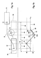
- FIGS. 1a, 1b show an exemplary situation for a parking operation according to the invention, wherein the FIG. 1b represents the associated angle impact.
- FIGS. 1a and 1b show together the exemplary situation on the basis of as FIG. 1a designated half above the dot-dash line and on the basis of as FIG. 1b designated half below the dot-dash line.
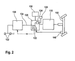
- FIG. 2 shows an embodiment of the controller according to the invention for carrying out the method according to the invention.
- FIG. 1a shows a vehicle in a first position 10 and a second position 10 ', wherein the vehicle with the reference numeral 10 after passing a parking space backwards in this parked and in the position 10' remains.
- the parking space extends between the vehicles 20, 22, whose circumference is shown in dashed lines and between which the parking space for the vehicle 10 'is arranged.
- the parking aid according to the invention controls the steering operation, so that when parking backward, a target path 30 results, which also corresponds to the actual trajectory. Considered is the movement of a point 12, 12 'of the vehicle 10, 10', which is deflected past the vehicle 22 at a distance 40.
- This point 12, 12 'of the vehicle 10, 10' is within the vehicle, so that there is a minimum distance r for a vehicle edge.
- the distance refers to the most critical part of the Vehicle 22, that is, the parking space facing corner, which is also the vehicle 10, 10 'facing.
- the desired trajectory includes a first portion 40 in which the vehicle is traveling straight ahead parallel to vehicle 22 to the left.
- a second section 42 in which the Einlenkwinkel ⁇ of the vehicle increases linearly, resulting in an increasing curvature.
- the Einlenkwinkel linearly reduced to a Einlenkwinkel ⁇ of zero.
- a deflection angle ⁇ of zero at which the setpoint or actual Trajectory at least currently corresponds to the longitudinal axis of the vehicle in the current position.
- the section 44 is followed by a section 46, in which the Einlenkwinkel ⁇ is increasingly increased until a maximum is reached.
- a fifth section 48 in which the orientation of the vehicle is aligned parallel to the original orientation, in which the steering angle ⁇ is reduced continuously (ie linearly) to zero.
- the Einlenkwinkel ⁇ is shown by a solid line, with the individual y-sections 40-48 to the respective location of the vehicle in the FIG. 1a Respectively.
- the solid line 50 corresponds to the course of the Einlenkwinkels in an ideal system that requires no calibration according to the invention.
- the steering angle to be controlled is increased in steps, see curve 52, the increments being the same in each case.
- the step width of the steerable Einlenkwinkels the course 152 is shown enlarged to better illustrate the invention. It can be seen that in the first iteration step 52a and in the second iteration step 52b, the steering angle to be controlled is also completely converted since the maximum steering value 60 'is not reached. During the incrementing step 152c, however, there is an error between the Einlenkwinkel of the curve 152 to be set and the exceeded actual maximum Einlenkwert shown in dotted line.
- This error between set steering angle of the iteration step 52c is compared with the actual maximum steering value 60 '(which also corresponds to the actual steering value during incrementing step 52c), the error being relatively small, as shown in FIG. 1b illustrated example, the Einlenkwinkel to be set in the incrementing step 52c is only slightly above the actual Maximaleinschwert (dashed lines), which also corresponds to the actual Einlenkwert.
- the error value is smaller than an error threshold, so that when comparing both values, no comparison result signal yet results, which corresponds to the occurrence of an error.
- an error 70 results which is clearly above the permissible error.
- the comparison with the error threshold results in detecting the occurrence of an error at this target angle.
- the adjustment angle to be set was within possible parameters, and the incrementing step 52d is too high to be set Einlenkwinkel (ie target angle) led. Therefore, the adjustment angle of the incrementing step 52c to be set is procedurally stored as a cap reflecting the correction parameter. In the following parking method, the stored correction value is then no longer exceeded in the amount of the Einlenkwinkels 52c.
- the steering angle to be controlled is automatically reduced to the value of the incrementing step 52c. At the same time this is taken into account in the specification of the desired trajectory to park the vehicle as desired, but without the steering system in operate in an area associated with excessive errors, which in turn would lead to undesirable misalignments of the vehicle to be parked.
- FIG. 2 shows a control according to the invention in overview block diagram.
- the system of FIG. 2 includes a steering system 100 of a vehicle (not shown), wherein the mechanical steering system 100 is mechanically actuated by an actuator 110.
- This actuator 110 corresponds to an electromechanical converter, which is electrically controlled by a drive unit 120.
- the drive unit 120 receives signals from a calculation unit 130, which predetermines a desired trajectory.
- the desired trajectory is detected by means of parking assist sensors 132, which are arranged as distance sensors on an outer side of the vehicle.
- parking assist sensors 132 which are arranged as distance sensors on an outer side of the vehicle.
- a vehicle camera and an image processing apparatus may be used for parking space detection.
- the steering system 100 is coupled to a sensor 140, which detects the actual deflection angle and passes it on to the feed-in unit 120, in particular to the comparator 122 of the feed-in unit at 120.
- the comparator 122 of the drive unit 120 further receives a desired Einlenkwinkel (as a result of the calculated desired trajectory), that is to be addressed Einlenkwinkel, via a connection 134, which also connects the drive unit 120 with the calculation unit 130.
- the comparator 122 compares the target specification, which is supplied through the connection 134 of the drive unit 120, with the sensor data of the sensor 140 to detect when the to be controlled Einlenkwinkel is no longer fully realized and thus the actual Einlenkwinkel is less than the controlled steered angle. The difference is detected by the comparator 122 as an error.
- the drive unit 120 further includes a threshold switch 124 which receives a maximum allowable error from a fault memory 126.
- the comparator 122 according to a preferred embodiment, which in FIG. 2 is shown in dashed lines, the error and in particular the associated Einlenkwinkel to the calculation unit 130 on (see dashed line), so that the calculation unit 130 can take into account the maximum Einlenkwert in the next calculation of the desired trajectory.
Landscapes
- Engineering & Computer Science (AREA)
- Chemical & Material Sciences (AREA)
- Combustion & Propulsion (AREA)
- Transportation (AREA)
- Mechanical Engineering (AREA)
- Steering Control In Accordance With Driving Conditions (AREA)
Applications Claiming Priority (2)
| Application Number | Priority Date | Filing Date | Title |
|---|---|---|---|
| DE102009028261A DE102009028261A1 (de) | 2009-08-05 | 2009-08-05 | Verfahren und Steuerung zur Kalibrierung einer automatisch lenkenden Einparkhilfe |
| PCT/EP2010/061256 WO2011015569A1 (de) | 2009-08-05 | 2010-08-03 | Verfahren und steuerung zur kalibrierung einer automatisch lenkenden einparkhilfe |
Publications (2)
| Publication Number | Publication Date |
|---|---|
| EP2462015A1 EP2462015A1 (de) | 2012-06-13 |
| EP2462015B1 true EP2462015B1 (de) | 2014-03-05 |
Family
ID=42830283
Family Applications (1)
| Application Number | Title | Priority Date | Filing Date |
|---|---|---|---|
| EP10739615.2A Active EP2462015B1 (de) | 2009-08-05 | 2010-08-03 | Verfahren und steuerung zur kalibrierung einer automatisch lenkenden einparkhilfe |
Country Status (7)
| Country | Link |
|---|---|
| US (1) | US9211912B2 (ja) |
| EP (1) | EP2462015B1 (ja) |
| JP (1) | JP5449552B2 (ja) |
| CN (1) | CN102574526B (ja) |
| DE (1) | DE102009028261A1 (ja) |
| IN (1) | IN2012DN01000A (ja) |
| WO (1) | WO2011015569A1 (ja) |
Families Citing this family (30)
| Publication number | Priority date | Publication date | Assignee | Title |
|---|---|---|---|---|
| DE102010062696A1 (de) * | 2010-12-09 | 2012-06-14 | Robert Bosch Gmbh | Verfahren und Vorrichtung zum Kalibrieren und Justieren eines Fahrzeug-Umfeldsensors. |
| DE102011086490A1 (de) | 2011-11-16 | 2013-05-16 | Robert Bosch Gmbh | Verfahren zur Bestimmung des dynamischen Abrollradius' von Reifen |
| KR20130119568A (ko) * | 2012-04-24 | 2013-11-01 | 현대모비스 주식회사 | 전동식 동력 조향장치를 이용한 차륜 정렬장치의 제어방법 |
| KR20130128893A (ko) * | 2012-05-18 | 2013-11-27 | 현대모비스 주식회사 | 주차 지원 시스템 및 방법 |
| CN102874252B (zh) * | 2012-08-30 | 2015-12-09 | 江苏大学 | 辅助泊车轨迹规划及修正方法及系统 |
| CN103332191A (zh) * | 2013-02-07 | 2013-10-02 | 江苏大学 | Eps集成的智能泊车控制系统和控制方法 |
| DE102013212031A1 (de) * | 2013-06-25 | 2015-01-08 | Schaeffler Technologies Gmbh & Co. Kg | Fahrassistenzsystem und -verfahren mit einer Wegregelung |
| KR101511992B1 (ko) * | 2013-09-06 | 2015-04-14 | 현대모비스(주) | 조향 휠 제어 방법 및 이를 위한 위한 시스템 |
| DE102014204983A1 (de) * | 2014-03-18 | 2015-09-24 | Robert Bosch Gmbh | Steuergerät und Verfahren zur Positionsbestimmung eines Fahrzeugs |
| CN105620473B (zh) * | 2014-10-27 | 2019-05-21 | 同致电子科技(厦门)有限公司 | 一种泊车轨迹校正方法 |
| JP2017030549A (ja) * | 2015-07-31 | 2017-02-09 | アイシン精機株式会社 | 駐車支援装置 |
| DE102015116220A1 (de) | 2015-09-25 | 2017-03-30 | Valeo Schalter Und Sensoren Gmbh | Verfahren zum zumindest semi-autonomen Manövrieren eines Kraftfahrzeugs mit Erkennung eines Odometriefehlers, Recheneinrichtung, Fahrerassistenzystem sowie Kraftfahrzeug |
| CN106696957A (zh) * | 2015-11-18 | 2017-05-24 | 上海航天汽车机电股份有限公司 | 一种车辆自动泊车控制方法及其系统 |
| FR3051756B1 (fr) * | 2016-05-24 | 2020-03-20 | Renault S.A.S | Dispositif de controle de trajectoire d’un vehicule |
| DE102016009760A1 (de) * | 2016-08-11 | 2018-02-15 | Trw Automotive Gmbh | Steuerungssystem und Steuerungsverfahren zum Führen eines Kraftfahrzeugs entlang eines Pfades |
| US9981686B2 (en) | 2016-08-31 | 2018-05-29 | Ford Global Technologies, Llc | Creep assist for steering management |
| US10618513B2 (en) * | 2016-09-13 | 2020-04-14 | Nissan Motor Co., Ltd. | Parking assist method and device |
| DE102017212044A1 (de) * | 2017-07-13 | 2019-01-17 | Robert Bosch Gmbh | Verfahren und Vorrichtung zum Berechnen einer Bewegungsbahn eines Fahrzeuges |
| CN107618503B (zh) * | 2017-08-29 | 2019-07-23 | 广州小鹏汽车科技有限公司 | 一种自动泊车控制方法及系统 |
| DE102018101388A1 (de) * | 2018-01-23 | 2019-07-25 | Valeo Schalter Und Sensoren Gmbh | Korrigieren einer Position eines Fahrzeugs mit SLAM |
| DE102018201411A1 (de) * | 2018-01-30 | 2019-08-01 | Robert Bosch Gmbh | Verfahren zum Ermitteln eines zeitlichen Verlaufs einer Messgröße, Prognosesystem, Aktorsteuerungssystem, Verfahren zum Trainieren des Aktorsteuerungssystems,Trainingssystem, Computerprogramm und maschinenlesbares Speichermedium |
| DE102018210358B4 (de) | 2018-06-26 | 2024-07-18 | Zf Friedrichshafen Ag | Verfahren zum autonomen Aufnehmen eines austauschbaren Lastenträgers |
| CN109895764B (zh) * | 2018-06-29 | 2023-06-27 | 华为技术有限公司 | 确定自动泊车策略的方法和装置 |
| US10850768B2 (en) * | 2018-09-11 | 2020-12-01 | Ford Global Technologies, Llc | Suspension-system degradation detection |
| CN109591808B (zh) * | 2018-10-18 | 2021-04-16 | 蔚来(安徽)控股有限公司 | 用于自动泊车系统的调试方法、装置及系统 |
| US11226623B2 (en) | 2019-04-03 | 2022-01-18 | Waymo Llc | Detection of anomalous trailer behavior |
| DE102019006935B4 (de) | 2019-10-04 | 2021-07-22 | Man Truck & Bus Se | Technik zur Totzeitkompensation bei Quer- und Längsführung eines Kraftfahrzeugs |
| DE102020105434A1 (de) * | 2020-03-02 | 2021-09-02 | Valeo Schalter Und Sensoren Gmbh | Verfahren zum betreiben eines fahrzeugs, parkassistenzsystem und fahrzeug |
| DE102020208391B4 (de) | 2020-07-03 | 2024-08-14 | Continental Autonomous Mobility Germany GmbH | Verfahren zur teil- oder vollautonomen Führung eines Kraftfahrzeugs |
| US20230339539A1 (en) * | 2022-04-21 | 2023-10-26 | Caterpillar Inc. | Alignment of Machine to Install Steering Frame Lock |
Family Cites Families (36)
| Publication number | Priority date | Publication date | Assignee | Title |
|---|---|---|---|---|
| JPH01187700A (ja) * | 1988-01-22 | 1989-07-27 | Alpine Electron Inc | 誘導誤差警告方法 |
| JP3223244B2 (ja) * | 1997-04-15 | 2001-10-29 | 本田技研工業株式会社 | 車両の自動操舵装置 |
| JP3044534B2 (ja) * | 1997-04-28 | 2000-05-22 | 本田技研工業株式会社 | 車両の自動操舵装置 |
| JP4129101B2 (ja) | 1999-07-02 | 2008-08-06 | 本田技研工業株式会社 | 車両の自動操舵装置 |
| JP2001255937A (ja) * | 2000-03-10 | 2001-09-21 | Toshiba Corp | 車両用自動走行制御装置 |
| JP4918200B2 (ja) * | 2001-04-24 | 2012-04-18 | パナソニック株式会社 | 駐車運転支援装置 |
| JP2003072495A (ja) * | 2001-09-06 | 2003-03-12 | Yazaki Corp | 駐車支援装置および駐車支援方法 |
| DE10261176A1 (de) * | 2002-12-20 | 2004-07-01 | Daimlerchrysler Ag | Verfahren und Vorrichtung zur Unterstützung des Fahrers eines Fahrzeugs bei einem Einparkfarmanöver |
| JP4058369B2 (ja) * | 2003-03-27 | 2008-03-05 | トヨタ自動車株式会社 | 駐車支援装置 |
| JP3949073B2 (ja) * | 2003-03-27 | 2007-07-25 | トヨタ自動車株式会社 | 駐車支援装置 |
| JP4345355B2 (ja) * | 2003-05-20 | 2009-10-14 | 日産自動車株式会社 | 操舵制御装置 |
| JP3911492B2 (ja) * | 2003-06-26 | 2007-05-09 | トヨタ自動車株式会社 | 車両用走行支援装置 |
| DE10331235A1 (de) * | 2003-07-10 | 2005-02-03 | Robert Bosch Gmbh | Fahrhilfsvorrichtung insbesondere zum Einparken eines Fahrzeugs |
| JP4167562B2 (ja) * | 2003-07-18 | 2008-10-15 | トヨタ自動車株式会社 | 車両用走行支援装置 |
| DE10336985A1 (de) * | 2003-08-12 | 2005-03-10 | Daimler Chrysler Ag | Verfahren zur Unterstützung des Fahrers bei Fahrmanövern |
| JP4657622B2 (ja) * | 2004-04-27 | 2011-03-23 | 株式会社アドヴィックス | 旋回制御装置、旋回制御方法および旋回制御プログラム |
| DE102004027250A1 (de) * | 2004-06-03 | 2005-12-29 | Magna Donnelly Gmbh & Co. Kg | Verfahren und Vorrichtung zum unterstützten Steuern eines Kraftfahrzeuges |
| JP4556500B2 (ja) * | 2004-06-04 | 2010-10-06 | 株式会社アドヴィックス | 車両の自動操舵制御装置 |
| JP4007360B2 (ja) * | 2004-10-25 | 2007-11-14 | 株式会社豊田自動織機 | 駐車支援装置 |
| DE102005014983A1 (de) * | 2004-12-15 | 2006-01-19 | Volkswagen Ag | Vorrichtung und Verfahren zur Unterstützung eines Fahrers beim Einparken eines Kraftfahrzeuges |
| JP4414959B2 (ja) * | 2005-11-16 | 2010-02-17 | アイシン精機株式会社 | 駐車支援装置 |
| KR101320223B1 (ko) * | 2005-12-23 | 2013-10-21 | 콘티넨탈 테베스 아게 운트 코. 오하게 | 자동차를 주차하거나 운전할 때 운전자를 돕기 위한 방법및 시스템 |
| JP2007302040A (ja) * | 2006-05-09 | 2007-11-22 | Toyota Motor Corp | 駐車支援装置 |
| DE102006030560A1 (de) * | 2006-07-03 | 2008-01-10 | Robert Bosch Gmbh | Verfahren zur Unterstützung eines Einparkvorgangs eines Fahrzeugs |
| US8538631B2 (en) * | 2007-01-23 | 2013-09-17 | GM Global Technology Operations LLC | Method and system for vehicle parking assistance |
| DE102007009745A1 (de) * | 2007-02-28 | 2008-09-04 | Continental Automotive Gmbh | Einparkhalbautomat |
| JP5105149B2 (ja) * | 2007-04-18 | 2012-12-19 | アイシン精機株式会社 | 駐車支援装置 |
| DE102007037645A1 (de) | 2007-08-10 | 2009-02-26 | Audi Ag | Kraftfahrzeug mit lenkbaren Vorder- und Hinterrädern |
| KR101013898B1 (ko) * | 2007-12-12 | 2011-02-14 | 현대자동차주식회사 | 차량용 자동주차 시스템 |
| DE102008000575A1 (de) * | 2008-03-07 | 2009-09-10 | Robert Bosch Gmbh | Verfahren und Vorrichtung zum Einparken eines Kraftfahrzeugs in eine Parklücke mittels eines Einparkassistenten |
| DE102008002699A1 (de) * | 2008-06-27 | 2009-12-31 | Robert Bosch Gmbh | Vorrichtung und Verfahren zum Steuern einer automatischen Lenkung eines Fahrzeugs und Vorrichtung und Verfahren zum Überprüfen einer Ausführbarkeit einer vorgegebenen Soll-Fahrtrichtungsgröße für ein Fahrzeug |
| JP2010149723A (ja) | 2008-12-25 | 2010-07-08 | Toyota Industries Corp | 駐車支援装置 |
| JP5403330B2 (ja) * | 2009-02-25 | 2014-01-29 | アイシン精機株式会社 | 駐車支援装置 |
| JP2010202010A (ja) * | 2009-03-02 | 2010-09-16 | Aisin Seiki Co Ltd | 駐車支援装置 |
| TWI347900B (en) * | 2009-03-10 | 2011-09-01 | Univ Nat Chiao Tung | Parking assistance system and method |
| US20100332080A1 (en) * | 2009-06-25 | 2010-12-30 | Hong Bae | Method and apparatus for parking assistance |
-
2009
- 2009-08-05 DE DE102009028261A patent/DE102009028261A1/de not_active Withdrawn
-
2010
- 2010-08-03 IN IN1000DEN2012 patent/IN2012DN01000A/en unknown
- 2010-08-03 CN CN201080044820.0A patent/CN102574526B/zh active Active
- 2010-08-03 EP EP10739615.2A patent/EP2462015B1/de active Active
- 2010-08-03 WO PCT/EP2010/061256 patent/WO2011015569A1/de not_active Ceased
- 2010-08-03 US US13/388,928 patent/US9211912B2/en active Active
- 2010-08-03 JP JP2012523316A patent/JP5449552B2/ja not_active Expired - Fee Related
Also Published As
| Publication number | Publication date |
|---|---|
| WO2011015569A1 (de) | 2011-02-10 |
| US9211912B2 (en) | 2015-12-15 |
| US20120197478A1 (en) | 2012-08-02 |
| IN2012DN01000A (ja) | 2015-04-10 |
| JP2013500901A (ja) | 2013-01-10 |
| EP2462015A1 (de) | 2012-06-13 |
| DE102009028261A1 (de) | 2011-02-10 |
| CN102574526A (zh) | 2012-07-11 |
| JP5449552B2 (ja) | 2014-03-19 |
| CN102574526B (zh) | 2015-09-09 |
Similar Documents
| Publication | Publication Date | Title |
|---|---|---|
| EP2462015B1 (de) | Verfahren und steuerung zur kalibrierung einer automatisch lenkenden einparkhilfe | |
| DE102014200100B4 (de) | Lenkwinkelfehlerkorrektur | |
| EP3856611B1 (de) | Verfahren zum ermitteln einer zahnstangenkraft eines steer-by-wire-lenksystems, steer-by-wire-lenksystem und fahrzeug | |
| DE102008026652B4 (de) | Lenkvorrichtung zum Einstellen eines Radeinschlagwinkels | |
| EP1585662B1 (de) | Verfahren zur synchronisation von lenkhandhabe und gelenkten fahrzeugrädern | |
| EP2022702B1 (de) | Kraftfahrzeug mit lenkbaren Vorder- und Hinterrädern | |
| EP0970875B1 (de) | Lenksystem für Kraftfahrzeuge | |
| EP3589531B1 (de) | Betriebsverfahren für ein steer-by-wire-lenksystem, steuereinheit für ein steer-by-wire-lenksystem, steer-by-wire-lenksystem und fahrzeug | |
| DE10101827A1 (de) | Lenkanordnung für Kraftfahrzeuge | |
| EP3392120B1 (de) | Steer-by-wire-lenkung und verfahren zur einstellung eines lenkwinkels bei einer steer-by-wire-lenkung | |
| EP1926646A1 (de) | Verfahren und vorrichtung zum durchführen eines ausweichmanövers | |
| DE102018102103A1 (de) | Verfahren zum Insassenschutz eines Kraftfahrzeuges mit einem Steer-by-Wire-Lenksystem | |
| WO2006081936A1 (de) | Verfahren und vorrichtung zur durchführung eines selbsttätigen lenkeingriffs, insbesondere zur spurhalteunterstützung | |
| DE102011122772A1 (de) | Elektrische Begrenzung eines Lenkeinrichtungsstellweges | |
| WO2016128108A1 (de) | Verfahren zum anlernen zulässiger lenkwinkel bei einer lenkeinrichtung eines kraftfahrzeugs | |
| DE10102244A1 (de) | Lenksytem für nicht spurgebundene Fahrzeuge | |
| EP3833593B1 (de) | Zahnstangenkraft optimiertes lenkgefühl einer steer-by-wire-kraftfahrzeuglenkung | |
| EP3932777B1 (de) | Endanschlags-rückstellfunktion für eine fahrzeuglenkung | |
| EP1837222A1 (de) | Anordnung zur Steuerung der Bewegung schwenkbarer Fahrzeugteile | |
| EP3623261B1 (de) | Verfahren zum einstellen eines rückkopplungsmoments an einer lenkhandhabe eines kraftfahrzeugs, lenksystem und kraftfahrzeug | |
| DE102013205877B4 (de) | Verfahren und Sicherheitsvorrichtung zum sicheren Betrieb eines Kraftfahrzeugs | |
| EP1486399B1 (de) | Verfahren und Lenksystem für die Mehrachslenkung eines Kraftfahrzeuges | |
| DE10011710B4 (de) | Verfahren zum Bestimmen einer Mittelstellung bei einem Fahrzeuglenksystem sowieLenksystem zur Durchführung des Verfahrens | |
| DE102007002264A1 (de) | Verfahren zum automatisierten Einparken eines Kraftfahrzeugs sowie Längsbewegungssteuerungseinrichtung für ein Kraftfahrzeug | |
| BE1031573A1 (de) | Fahrzeug, insbesondere Kraftfahrzeug, sowie Verfahren zur Kontrolle der Stabilität eines Fahrzeuges |
Legal Events
| Date | Code | Title | Description |
|---|---|---|---|
| PUAI | Public reference made under article 153(3) epc to a published international application that has entered the european phase |
Free format text: ORIGINAL CODE: 0009012 |
|
| 17P | Request for examination filed |
Effective date: 20120305 |
|
| AK | Designated contracting states |
Kind code of ref document: A1 Designated state(s): AL AT BE BG CH CY CZ DE DK EE ES FI FR GB GR HR HU IE IS IT LI LT LU LV MC MK MT NL NO PL PT RO SE SI SK SM TR |
|
| DAX | Request for extension of the european patent (deleted) | ||
| GRAP | Despatch of communication of intention to grant a patent |
Free format text: ORIGINAL CODE: EPIDOSNIGR1 |
|
| INTG | Intention to grant announced |
Effective date: 20131202 |
|
| GRAS | Grant fee paid |
Free format text: ORIGINAL CODE: EPIDOSNIGR3 |
|
| GRAA | (expected) grant |
Free format text: ORIGINAL CODE: 0009210 |
|
| AK | Designated contracting states |
Kind code of ref document: B1 Designated state(s): AL AT BE BG CH CY CZ DE DK EE ES FI FR GB GR HR HU IE IS IT LI LT LU LV MC MK MT NL NO PL PT RO SE SI SK SM TR |
|
| REG | Reference to a national code |
Ref country code: GB Ref legal event code: FG4D Free format text: NOT ENGLISH |
|
| REG | Reference to a national code |
Ref country code: CH Ref legal event code: EP |
|
| REG | Reference to a national code |
Ref country code: AT Ref legal event code: REF Ref document number: 654649 Country of ref document: AT Kind code of ref document: T Effective date: 20140315 |
|
| REG | Reference to a national code |
Ref country code: IE Ref legal event code: FG4D Free format text: LANGUAGE OF EP DOCUMENT: GERMAN |
|
| REG | Reference to a national code |
Ref country code: DE Ref legal event code: R096 Ref document number: 502010006282 Country of ref document: DE Effective date: 20140410 |
|
| REG | Reference to a national code |
Ref country code: NL Ref legal event code: VDEP Effective date: 20140305 |
|
| PG25 | Lapsed in a contracting state [announced via postgrant information from national office to epo] |
Ref country code: NO Free format text: LAPSE BECAUSE OF FAILURE TO SUBMIT A TRANSLATION OF THE DESCRIPTION OR TO PAY THE FEE WITHIN THE PRESCRIBED TIME-LIMIT Effective date: 20140605 Ref country code: LT Free format text: LAPSE BECAUSE OF FAILURE TO SUBMIT A TRANSLATION OF THE DESCRIPTION OR TO PAY THE FEE WITHIN THE PRESCRIBED TIME-LIMIT Effective date: 20140305 |
|
| REG | Reference to a national code |
Ref country code: LT Ref legal event code: MG4D |
|
| PG25 | Lapsed in a contracting state [announced via postgrant information from national office to epo] |
Ref country code: SE Free format text: LAPSE BECAUSE OF FAILURE TO SUBMIT A TRANSLATION OF THE DESCRIPTION OR TO PAY THE FEE WITHIN THE PRESCRIBED TIME-LIMIT Effective date: 20140305 Ref country code: FI Free format text: LAPSE BECAUSE OF FAILURE TO SUBMIT A TRANSLATION OF THE DESCRIPTION OR TO PAY THE FEE WITHIN THE PRESCRIBED TIME-LIMIT Effective date: 20140305 Ref country code: CY Free format text: LAPSE BECAUSE OF FAILURE TO SUBMIT A TRANSLATION OF THE DESCRIPTION OR TO PAY THE FEE WITHIN THE PRESCRIBED TIME-LIMIT Effective date: 20140305 |
|
| PG25 | Lapsed in a contracting state [announced via postgrant information from national office to epo] |
Ref country code: HR Free format text: LAPSE BECAUSE OF FAILURE TO SUBMIT A TRANSLATION OF THE DESCRIPTION OR TO PAY THE FEE WITHIN THE PRESCRIBED TIME-LIMIT Effective date: 20140305 Ref country code: LV Free format text: LAPSE BECAUSE OF FAILURE TO SUBMIT A TRANSLATION OF THE DESCRIPTION OR TO PAY THE FEE WITHIN THE PRESCRIBED TIME-LIMIT Effective date: 20140305 |
|
| PG25 | Lapsed in a contracting state [announced via postgrant information from national office to epo] |
Ref country code: BG Free format text: LAPSE BECAUSE OF FAILURE TO SUBMIT A TRANSLATION OF THE DESCRIPTION OR TO PAY THE FEE WITHIN THE PRESCRIBED TIME-LIMIT Effective date: 20140605 Ref country code: RO Free format text: LAPSE BECAUSE OF FAILURE TO SUBMIT A TRANSLATION OF THE DESCRIPTION OR TO PAY THE FEE WITHIN THE PRESCRIBED TIME-LIMIT Effective date: 20140305 Ref country code: IS Free format text: LAPSE BECAUSE OF FAILURE TO SUBMIT A TRANSLATION OF THE DESCRIPTION OR TO PAY THE FEE WITHIN THE PRESCRIBED TIME-LIMIT Effective date: 20140705 Ref country code: CZ Free format text: LAPSE BECAUSE OF FAILURE TO SUBMIT A TRANSLATION OF THE DESCRIPTION OR TO PAY THE FEE WITHIN THE PRESCRIBED TIME-LIMIT Effective date: 20140305 Ref country code: EE Free format text: LAPSE BECAUSE OF FAILURE TO SUBMIT A TRANSLATION OF THE DESCRIPTION OR TO PAY THE FEE WITHIN THE PRESCRIBED TIME-LIMIT Effective date: 20140305 Ref country code: NL Free format text: LAPSE BECAUSE OF FAILURE TO SUBMIT A TRANSLATION OF THE DESCRIPTION OR TO PAY THE FEE WITHIN THE PRESCRIBED TIME-LIMIT Effective date: 20140305 |
|
| PG25 | Lapsed in a contracting state [announced via postgrant information from national office to epo] |
Ref country code: ES Free format text: LAPSE BECAUSE OF FAILURE TO SUBMIT A TRANSLATION OF THE DESCRIPTION OR TO PAY THE FEE WITHIN THE PRESCRIBED TIME-LIMIT Effective date: 20140305 Ref country code: PL Free format text: LAPSE BECAUSE OF FAILURE TO SUBMIT A TRANSLATION OF THE DESCRIPTION OR TO PAY THE FEE WITHIN THE PRESCRIBED TIME-LIMIT Effective date: 20140305 Ref country code: SK Free format text: LAPSE BECAUSE OF FAILURE TO SUBMIT A TRANSLATION OF THE DESCRIPTION OR TO PAY THE FEE WITHIN THE PRESCRIBED TIME-LIMIT Effective date: 20140305 |
|
| REG | Reference to a national code |
Ref country code: DE Ref legal event code: R097 Ref document number: 502010006282 Country of ref document: DE |
|
| PG25 | Lapsed in a contracting state [announced via postgrant information from national office to epo] |
Ref country code: PT Free format text: LAPSE BECAUSE OF FAILURE TO SUBMIT A TRANSLATION OF THE DESCRIPTION OR TO PAY THE FEE WITHIN THE PRESCRIBED TIME-LIMIT Effective date: 20140707 |
|
| PLBE | No opposition filed within time limit |
Free format text: ORIGINAL CODE: 0009261 |
|
| STAA | Information on the status of an ep patent application or granted ep patent |
Free format text: STATUS: NO OPPOSITION FILED WITHIN TIME LIMIT |
|
| PG25 | Lapsed in a contracting state [announced via postgrant information from national office to epo] |
Ref country code: DK Free format text: LAPSE BECAUSE OF FAILURE TO SUBMIT A TRANSLATION OF THE DESCRIPTION OR TO PAY THE FEE WITHIN THE PRESCRIBED TIME-LIMIT Effective date: 20140305 |
|
| 26N | No opposition filed |
Effective date: 20141208 |
|
| REG | Reference to a national code |
Ref country code: DE Ref legal event code: R097 Ref document number: 502010006282 Country of ref document: DE Effective date: 20141208 |
|
| PG25 | Lapsed in a contracting state [announced via postgrant information from national office to epo] |
Ref country code: LU Free format text: LAPSE BECAUSE OF FAILURE TO SUBMIT A TRANSLATION OF THE DESCRIPTION OR TO PAY THE FEE WITHIN THE PRESCRIBED TIME-LIMIT Effective date: 20140803 Ref country code: MC Free format text: LAPSE BECAUSE OF FAILURE TO SUBMIT A TRANSLATION OF THE DESCRIPTION OR TO PAY THE FEE WITHIN THE PRESCRIBED TIME-LIMIT Effective date: 20140305 Ref country code: IT Free format text: LAPSE BECAUSE OF FAILURE TO SUBMIT A TRANSLATION OF THE DESCRIPTION OR TO PAY THE FEE WITHIN THE PRESCRIBED TIME-LIMIT Effective date: 20140305 |
|
| REG | Reference to a national code |
Ref country code: CH Ref legal event code: PL |
|
| PG25 | Lapsed in a contracting state [announced via postgrant information from national office to epo] |
Ref country code: LI Free format text: LAPSE BECAUSE OF NON-PAYMENT OF DUE FEES Effective date: 20140831 Ref country code: CH Free format text: LAPSE BECAUSE OF NON-PAYMENT OF DUE FEES Effective date: 20140831 Ref country code: BE Free format text: LAPSE BECAUSE OF NON-PAYMENT OF DUE FEES Effective date: 20140831 |
|
| REG | Reference to a national code |
Ref country code: IE Ref legal event code: MM4A |
|
| PG25 | Lapsed in a contracting state [announced via postgrant information from national office to epo] |
Ref country code: SI Free format text: LAPSE BECAUSE OF FAILURE TO SUBMIT A TRANSLATION OF THE DESCRIPTION OR TO PAY THE FEE WITHIN THE PRESCRIBED TIME-LIMIT Effective date: 20140305 |
|
| PG25 | Lapsed in a contracting state [announced via postgrant information from national office to epo] |
Ref country code: IE Free format text: LAPSE BECAUSE OF NON-PAYMENT OF DUE FEES Effective date: 20140803 |
|
| PG25 | Lapsed in a contracting state [announced via postgrant information from national office to epo] |
Ref country code: SM Free format text: LAPSE BECAUSE OF FAILURE TO SUBMIT A TRANSLATION OF THE DESCRIPTION OR TO PAY THE FEE WITHIN THE PRESCRIBED TIME-LIMIT Effective date: 20140305 |
|
| PG25 | Lapsed in a contracting state [announced via postgrant information from national office to epo] |
Ref country code: GR Free format text: LAPSE BECAUSE OF FAILURE TO SUBMIT A TRANSLATION OF THE DESCRIPTION OR TO PAY THE FEE WITHIN THE PRESCRIBED TIME-LIMIT Effective date: 20140606 Ref country code: MT Free format text: LAPSE BECAUSE OF FAILURE TO SUBMIT A TRANSLATION OF THE DESCRIPTION OR TO PAY THE FEE WITHIN THE PRESCRIBED TIME-LIMIT Effective date: 20140305 |
|
| PG25 | Lapsed in a contracting state [announced via postgrant information from national office to epo] |
Ref country code: TR Free format text: LAPSE BECAUSE OF FAILURE TO SUBMIT A TRANSLATION OF THE DESCRIPTION OR TO PAY THE FEE WITHIN THE PRESCRIBED TIME-LIMIT Effective date: 20140305 Ref country code: HU Free format text: LAPSE BECAUSE OF FAILURE TO SUBMIT A TRANSLATION OF THE DESCRIPTION OR TO PAY THE FEE WITHIN THE PRESCRIBED TIME-LIMIT; INVALID AB INITIO Effective date: 20100803 |
|
| REG | Reference to a national code |
Ref country code: FR Ref legal event code: PLFP Year of fee payment: 7 |
|
| REG | Reference to a national code |
Ref country code: AT Ref legal event code: MM01 Ref document number: 654649 Country of ref document: AT Kind code of ref document: T Effective date: 20150803 |
|
| PG25 | Lapsed in a contracting state [announced via postgrant information from national office to epo] |
Ref country code: AT Free format text: LAPSE BECAUSE OF NON-PAYMENT OF DUE FEES Effective date: 20150803 |
|
| REG | Reference to a national code |
Ref country code: FR Ref legal event code: PLFP Year of fee payment: 8 |
|
| PG25 | Lapsed in a contracting state [announced via postgrant information from national office to epo] |
Ref country code: MK Free format text: LAPSE BECAUSE OF FAILURE TO SUBMIT A TRANSLATION OF THE DESCRIPTION OR TO PAY THE FEE WITHIN THE PRESCRIBED TIME-LIMIT Effective date: 20140305 |
|
| REG | Reference to a national code |
Ref country code: FR Ref legal event code: PLFP Year of fee payment: 9 |
|
| PG25 | Lapsed in a contracting state [announced via postgrant information from national office to epo] |
Ref country code: AL Free format text: LAPSE BECAUSE OF FAILURE TO SUBMIT A TRANSLATION OF THE DESCRIPTION OR TO PAY THE FEE WITHIN THE PRESCRIBED TIME-LIMIT Effective date: 20140305 |
|
| PGFP | Annual fee paid to national office [announced via postgrant information from national office to epo] |
Ref country code: GB Payment date: 20230824 Year of fee payment: 14 |
|
| PGFP | Annual fee paid to national office [announced via postgrant information from national office to epo] |
Ref country code: FR Payment date: 20230821 Year of fee payment: 14 |
|
| REG | Reference to a national code |
Ref country code: DE Ref legal event code: R084 Ref document number: 502010006282 Country of ref document: DE |
|
| PGFP | Annual fee paid to national office [announced via postgrant information from national office to epo] |
Ref country code: DE Payment date: 20241024 Year of fee payment: 15 |
|
| GBPC | Gb: european patent ceased through non-payment of renewal fee |
Effective date: 20240803 |
|
| PG25 | Lapsed in a contracting state [announced via postgrant information from national office to epo] |
Ref country code: GB Free format text: LAPSE BECAUSE OF NON-PAYMENT OF DUE FEES Effective date: 20240803 |
|
| PG25 | Lapsed in a contracting state [announced via postgrant information from national office to epo] |
Ref country code: FR Free format text: LAPSE BECAUSE OF NON-PAYMENT OF DUE FEES Effective date: 20240831 |