EP2462011B1 - Landing gear - Google Patents
Landing gear Download PDFInfo
- Publication number
- EP2462011B1 EP2462011B1 EP10737029.8A EP10737029A EP2462011B1 EP 2462011 B1 EP2462011 B1 EP 2462011B1 EP 10737029 A EP10737029 A EP 10737029A EP 2462011 B1 EP2462011 B1 EP 2462011B1
- Authority
- EP
- European Patent Office
- Prior art keywords
- drive shaft
- support leg
- cogged crown
- cursor
- wheel
- Prior art date
- Legal status (The legal status is an assumption and is not a legal conclusion. Google has not performed a legal analysis and makes no representation as to the accuracy of the status listed.)
- Active
Links
Images


Classifications
-
- B—PERFORMING OPERATIONS; TRANSPORTING
- B60—VEHICLES IN GENERAL
- B60S—SERVICING, CLEANING, REPAIRING, SUPPORTING, LIFTING, OR MANOEUVRING OF VEHICLES, NOT OTHERWISE PROVIDED FOR
- B60S9/00—Ground-engaging vehicle fittings for supporting, lifting, or manoeuvring the vehicle, wholly or in part, e.g. built-in jacks
- B60S9/02—Ground-engaging vehicle fittings for supporting, lifting, or manoeuvring the vehicle, wholly or in part, e.g. built-in jacks for only lifting or supporting
- B60S9/04—Ground-engaging vehicle fittings for supporting, lifting, or manoeuvring the vehicle, wholly or in part, e.g. built-in jacks for only lifting or supporting mechanically
- B60S9/06—Ground-engaging vehicle fittings for supporting, lifting, or manoeuvring the vehicle, wholly or in part, e.g. built-in jacks for only lifting or supporting mechanically of screw-and-nut type
- B60S9/08—Ground-engaging vehicle fittings for supporting, lifting, or manoeuvring the vehicle, wholly or in part, e.g. built-in jacks for only lifting or supporting mechanically of screw-and-nut type the screw axis being substantially vertical
Definitions
- the invention relates to support legs which are normally fitted to trailers, construction machines, agricultural machines, industrial vehicles, transport carriages or any type of vehicle to enable stable support thereof on the ground when the machine is stationary.
- the present invention relates to extensible support legs which can take on a shortened configuration, in which the lower end thereof is raised from the ground, and an extended configuration, in which the lower end thereof rests on the ground.
- extensible support legs schematically comprise a telescopic column which is fixed to the vehicle, and a contact organ which is fixed to the lower end of the telescopic column.
- the contact organ is generally a platform or a small wheel.
- the telescopic column comprises at least two coaxial tubes, of which one is an external tube and another is an internal tube which is slidably inserted in the external tube.
- the contact organ is fixed to the lower end of the internal tube which projects from the external tube.
- the lengthening and shortening of the telescopic column are obtained by a manoeuvring screw which is inserted in the coaxial tubes.
- the manoeuvring screw is axially constrained to the external tube, and is screwed into a threaded volute axially constrained to the internal tube.
- the rotation of the manoeuvring screw causes an axial sliding of the internal tube in an upwards direction or in a downwards direction.
- the rotation of the manoeuvring screw is activated by a drive shaft.
- the drive shaft is connected to the manoeuvring screw by an intermediate gear and is rotated by a motor or a manually-activated handle.
- the telescopic column When the vehicle is to be stabilised on the ground, the telescopic column is extended up to when the contact organ rests on the ground, after which it is further extended such as to raise and support at least part of the load.
- an intermediate gear can be used for realising a rather high transmission ratio between the drive shaft and the manoeuvring screw.
- a known solution is to interpose a mechanical gear change between the drive shaft and the manoeuvring screw, which can produce at least two different transmission ratios.
- patent application CA 2 659 294 illustrates a support leg with a mechanical gear change that comprises two gears with a different transmission ratio.
- Each of the gears comprises a first cog wheel mounted on the drive shaft, which enmeshes with a second cog wheel mounted on an intermediate shaft, and a third cog wheel mounted on the intermediate shaft, which in turn enmeshes with a fourth cog wheel mounted on the manoeuvring screw.
- the first cog wheel of each gear is rotatably idle on the drive shaft, which is axially mobile, in order to activate an enmeshing system which renders it rotatably solid with the first cog wheel of one or the other gear.
- US patent 2008/0315570 describes a support leg having a mechanical gear change which also comprises an intermediate shaft, kinematically interposed between the drive shaft and the manoeuvring screw.
- the intermediate shaft is connected to the manoeuvring screw via a single gear, while it is connected to the drive shaft via two further gears having different transmission ratios.
- the drive shaft is axially mobile in order to activate an enmeshing system which renders one or the other of the further gears active.
- EP patent EP 1 350 701 also describes a mechanical gear change provided with an intermediate shaft, which is connected to the drive shaft by means of two gears with a different transmission ratio, selectively activatable by means of an enmeshing system, while it is connected to the manoeuvring screw by a single gear with a fixed transmission ratio.
- German patent application DE 196 16 704 describes a support leg of traditional type, wherein the manoeuvring screw is connected to an intermediate shaft by means of a fixed gear, while the intermediate shaft is connected to the drive shaft by means of a gear change which is housed in a box located externally of the support leg.
- An aim of the present invention is to make available a support leg with a gear change that is simpler, more compact and less expensive in relation to the known solutions, but which is equally functional and effective.
- a further aim is to provide a gear change which is in any case able to effectively limit the torque to be applied to the drive shaft in the second extension stage of the support leg, during which the load is raised, guaranteeing however a sufficient rapidity of the first stage of extension during which the contact organ is neared to the ground.
- a further aim of the invention is to reach the above-mentioned objective in the ambit of a simple, rational and relatively inexpensive solution.
- an extensible support foot which overall comprises at least two reciprocally-slidable portions, a manoeuvring screw axially constrained to a first of the portions, a threaded volute axially constrained to a second of the portions and screwed on the manoeuvring screw, and a rotating drive shaft, which is connected to the manoeuvring screw by means of a mechanical gear change, and is destined to be rotated in order to rotate in turn the manoeuvring screw, such as to cause a reciprocal sliding of the first and second portions.
- the gear change comprises at least:
- the lower transmission ratio can be used in the first stage of extension of the support leg, such as to reduce the revolutions of the drive shaft required, and therefore the time needed in order to bring the support organ to the ground.
- the higher transmission ratio can be used in the second stage of extension of the support leg, such as to minimise the torque to be applied to the drive shaft in order to obtain the raising of the load.
- the higher gear ratio can also be used in the first retracting stage of the support leg, during which the load bearing down on the support leg is gradually lowered, while the lower transmission ratio can be re-used during the second retraction stage of the support leg, during which the contact organ is raised into the initial position.
- the support leg comprises exactly one rotating shaft alone, connected in a kinematic mechanism with the manoeuvring screw, the rotating shaft being the above-mentioned drive shaft.
- the cursor of the gear change is axially blocked on the drive shaft, which is mobile in the direction of the axis thereof such as to move the cursor between the enmeshed positions.
- the gear change can be manually activated by a user, simply by rotating and moving the drive shaft in an axial direction.
- the cursor exhibits opposite lateral sides, each of which is provided with at least a frontal cog destined to couple with at least a frontal cog of the second cogged crown wheel facing it, in order to enmesh there-with.
- This solution has the advantage of providing an enmeshing system which is very simple and reliable.
- the first cogged crown wheels, associated to the manoeuvring screw, are made in a single body.
- first cogged crown wheels can also be made in two separate bodies.
- the support leg also comprises a handle destined to be manually activated in order to set the drive shaft in rotation.
- the handle can be made in a single body with the drive shaft or can be realised separately and mounted thereon.
- the drive shaft could be connected to a motor destined to set it in rotation.
- the cursor could be associated to automatic means for moving it between the enmeshed positions.
- the support leg 1 is destined to be mounted on trailers, construction machines, agricultural machines, industrial vehicles, transport carriages or any other type of vehicle, in order to enable a stable rest on the ground when stationary and/or unhooked from the drive shaft.
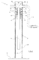
- the support leg 1 comprises a vertical-axis telescopic column 2, at a lower end of which a platform 3 is fitted, which platform 3 is destined to be rested on the ground.
- the platform 3 can be replaced by any other contact organ, for example a wheel.
- the telescopic column 2 comprises two coaxial tubes, of which one is an external tube 20 and another an internal tube 21, which is slidably inserted in the external tube 20.
- the coaxial tubes 20 and 21 both have prismatic transversal sections (see for example figures 4 and 5 ), such that they can reciprocally slide in an axial direction but which are reciprocally blocked in rotation.
- coaxial tubes 20 and 21 might have a circular transversal section.
- the platform 3 is welded to the lower end of the internal tube 21 which projects from the external tube 20.
- the external tube 20 is destined to be fixed on the vehicle, such that the internal tube 21 can slide between the retracted position of figure 1 , in which the platform 3 is raised from the ground, and an extracted position (not illustrated), in which the platform 3 rests on the ground.
- a threaded volute 4 is fixed to the upper end of the internal tube 21.
- the threaded volute 4 comprises an upper shoulder 40 which rests on the edge of the internal tube 21, and a lower portion 41 which is jointed internally of the internal tube 21.
- the threaded volute 4 is further fixed to the internal tube 21 by two transversal pins 42, each of which is inserted in a respective hole afforded in the lower portion 41 from which each pin 42 projects with a head tract thereof that is engaged in a hole afforded in the internal tube 21.
- the threaded volute 4 is solidly constrained to the internal tube 21 axially, and cannot even rotate about the vertical axis thereof.
- a vertical-axis manoeuvring screw 5 is screwed into the threaded volute 4, which screw 5 is coaxially inserted internally of the external tube 20 and the internal tube 21.
- the upper end of the manoeuvring screw 5 comprises a coaxial cylindrical spur 50 which projects above the threaded volute 4.
- the cylindrical spur 50 has a smaller diameter than the manoeuvring screw 5, such that a striker abutment 51 remains defined there-between.
- the cylindrical spur 50 is inserted in a through-hole afforded centrally in a plate 6 which is welded internally of the external tube 20.
- annular spacer 52 resting on or welded to the striker abutment 51, and a thrust bearing 53, in contact with bother the annular spacer 52 and the plate 6, are inserted on a tract of the cylindrical spur 50 comprised between the plate 6 and the manoeuvring screw 5.
- a gear wheel 7 is constrained on the tract of the cylindrical spur 50 projecting above the plate 6, which gear wheel 7 rotates solidly with the manoeuvring screw 5.
- the gear wheel 7, the plate 6, the thrust bearing 53 and the annular spacer 52 are blocked in a stack between the striker abutment 51 of the manoeuvring screw 5 and an elastic seeger ring 54, or another retaining system, which is fixed to the end of the cylindrical spur 50.
- the manoeuvring screw 5 is axially constrained to the external tube 20, and is free to rotate about the vertical axis thereof, solidly with the gear wheel 7.
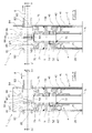
- the gear wheel 7 comprises two conical cogged crown wheels, reciprocally coaxial and having the cogs thereof facing upwards, of which one is an internal cogged crown wheel 70 and the other is an external cogged crown wheel 71.
- Each cogged crown wheel 70 and 71 enmeshes with a horizontal-axis cogged crown wheel, respectively with a first gear wheel 80 and a second gear wheel 81.
- the transmission ratio realised between the first gear wheel 80 and the internal cogged crown wheel 70 is greater than the transmission ratio realised between the second gear wheel 81 and the external cogged crown wheel 71.
- the transmission ration between the first gear wheel 80 and the internal cogged crown wheel 70 is greater than 1 (one), as the primitive diameter of the gear wheel 80 is greater than the primitive diameter of the cogged crown wheel 70, such that they have a multiplication ratio in which for each complete revolution of the gear wheel 80 the gear wheel 7 performs more than one complete revolution.
- the transmission ratio between the second gear wheel 81 and the external cogged crown wheel 71 has a minimum value of 1 (one), as the primitive diameter of the gearwheel 81 is less than the primitive diameter of the cogged crown wheel 71, such that they have a reduction ratio such that for each complete revolution of the gearwheel 81 there is less than a complete revolution of the gear wheel 7.
- the gear wheels 80 and 81 are coaxially inserted idle on a same rotating horizontal-axis drive shaft 8, which is inserted and maintained in two reciprocally-aligned through-holes afforded in the lateral walls of the external tube 20.
- Plastic bushings 82 and 83 are interposed between the drive shaft 8 and each through-hole of the external tube 20, which plastic bushings reduce rotation friction.
- plastic bushings 82 and 83 can be absent.
- the drive shaft 8 is free to slide axially with respect to the gear wheels 80 and 81, which are axially stationary such as to constantly enmesh with the respective cogged crown wheels 70 and 71.
- the gear wheel 81 is axially blocked between the bush 82 and the cogged crown wheel 70, while the gear wheel 80 is axially blocked between the cogged crown wheel 71 and the bush 83 with the interposing of a spacer 84.
- the gear wheels 80 and 81 are coaxial but arranged on diametrically opposite sides with respect to the rotation axis of the manoeuvring screw 5; the gear wheels 80 and 81 are destined always to rotate in opposite directions.
- Each gear wheel 80 and 81 further comprises one or more frontal cogs 85 which project from the surface facing towards the other gear wheel.
- annular cursor 86 is inserted on the tract of the drive shaft 8 comprised between the gear wheels 80 and 81, opposite lateral flanks of which annular cursor 86 both comprise one or more frontal cogs 87 destined to cooperate with the frontal cogs 85 of the gear wheel 80 or 81, such as to realise an enmeshing which constrains the gear wheel 80 and 81 to the annular cursor 86 in rotation.
- the annular cursor 86 is axially and rotatingly solidly constrained to the drive shaft 8 by means of a transversal elastic plug 88, which is snugly inserted in a corresponding through-hole 89 passing through the drive shaft 8.
- the annular cursor 86 can slide forwards and backwards together with the drive shaft 8, in order to couple alternatively with the gear wheel 80 or the gear wheel 81.
- annular cursor 86 together with the gear wheels 80, 81 and the gear wheel 7 establishes a mechanical gear change between the horizontal drive shaft 8 and the vertical manoeuvring screw 5, without there being any need for another intermediate rotating shaft.
- the support leg 1 is provided with a handle 9 which is fixed to an end of the drive shaft 8 which projects from the external tube 20, such as to able to be gripped and manually activated to cause rotation of the drive shaft 8 itself.
- the handle 9 can be replaced by any other manual or automatic activating organ, among which for example an electric motor.
- the rotation of the drive shaft 8 is transmitted via the gears of the gear change to the manoeuvring screw 5 which, thanks to the threaded volute 4, transforms it into an axial movement of the internal tube 21 in the external tube 20 and thus into an extension or retraction of the support leg 1.
- the gear wheel 81 rotates idle on the drive shaft 8 in the opposite direction to the gear wheel 80, drawn by the cogged crown wheel 71.
- the larger transmission ratio existing between the gear wheel 80 and the cogged crown wheel 70 enables the support leg to be extended or retracted rapidly, i.e. making the drive shaft 8 perform a smaller number of rotations.
- the annular cursor 86 is enmeshed with the gear wheel 81 as illustrated in figures 2 and 4 , the transmission of the motor between the drive shaft 8 and the manoeuvring screw 5 occurs via the enmeshment between the gear wheel 81 and the external cogged crown wheel 71.
- the gear wheel 80 rotates idle on the drive shaft 8 in an opposite direction with respect to the cogged crown wheel 81, drawn by the cogged crown wheel 70.
- the smaller transmission ratio between the gear wheel 81 and the cogged crown wheel 71 enables the support leg 1 to be extended or retracted with less effort, i.e. with a smaller torque applied on the drive shaft 8 given a same load applied on the support leg 1.
- the support leg 1 is initially in the configuration shown in figure 1 , in which the external tube 20 is fixed to a vehicle and the internal tube 21 is raised from the ground.
- the support leg 1 is subjected to a first extension, up to bringing the platform 3 into contact with the ground, and then to a further second extension, such as at least partially to raise the load.
- a further second extension such as at least partially to raise the load.
- the support leg 1 is not subjected to the load.
- the gear change is brought into the configuration of figure 3 , such that the greater transmission ratio between the gear wheel 80 and the cogged crown wheel 81 enables the platform 3 to be quickly lowered.
- the support leg 1 is subjected to the load.
- the gear change is displaced into the configuration of figure 2 such that the lower transmission ratio between the gear wheel 81 and the cogged crown wheel 71 enables the load to be raised by applying a relatively small torque on the drive shaft 8.
- the support leg 1 is subjected to a first retraction, up to when it rests its load completely on the drive shaft, and then to a second further retraction, such as to return the platform 3, also known as a base, into the initial position of figure 1 .
- the support leg 1 is still subjected to the load.
- the gear change can therefore be returned into the configuration of figure 3 , such that the greater transmission ratio between the gear wheel 80 and the cogged crown wheel 70 enables the platform 3 to be quickly raised.
- FIG. 6 a support leg 1 is illustrated which shows a second embodiment of the invention.
- This second embodiment is structurally and functionally similar to the preceding one, and differs from it only in some constructional aspects, the most important of which are delineated in the following.
- the gearings 80, 81, 70, 71 of the gear change are contained internally of a separate casing 22 which is welded to the top of the external tube 20.
- the bottom wall of the casing 22 replaces the plate 6 in the first embodiment, and the drive shaft 8 is inserted internally of the holes which are afforded in the lateral walls of the casing 22.
- the gear wheel 81 is therefore directly rested against a lateral wall of the casing 22, while the gear wheel 80 is rested against the opposite lateral wall with only the interposing of a spacer 84.
- the activating handle 9 is fashioned in a single body with the drive shaft 8.
- the external cogged crown wheel 71 and the internal cogged crown wheel 70 are realised in two separate bodies 7' and 7", which are coaxially inserted on the tract of cylindrical spur 50 which projects internally of the casing 22.
- the external cogged crown wheel 71 and the internal cogged crown wheel 70 could in this case too be realised in a single body as in the preceding embodiment.
- the external cogged crown wheel 71 and the internal cogged crown wheel 70 are made solid in rotation with the cylindrical spur 50 by means of a single tab 55 or other constraining system.
- the internal tube 21 is constrained to the threaded volute 4, realising series of swellings 43 by plastic deformation, which swellings 43 engage in respective recesses afforded in the threaded volute 4, thus eliminating the need for the transversal pins 42.
Landscapes
- Engineering & Computer Science (AREA)
- Mechanical Engineering (AREA)
- Gear Transmission (AREA)
- Transmission Devices (AREA)
- Finger-Pressure Massage (AREA)
- Percussion Or Vibration Massage (AREA)
Priority Applications (2)
| Application Number | Priority Date | Filing Date | Title |
|---|---|---|---|
| PL10737029T PL2462011T3 (pl) | 2009-08-04 | 2010-07-22 | Podwozie |
| SI201030317T SI2462011T1 (sl) | 2009-08-04 | 2010-07-22 | Podporna noga |
Applications Claiming Priority (2)
| Application Number | Priority Date | Filing Date | Title |
|---|---|---|---|
| ITRE2009A000082A IT1395539B1 (it) | 2009-08-04 | 2009-08-04 | Piede d'appoggio |
| PCT/EP2010/060667 WO2011015467A1 (en) | 2009-08-04 | 2010-07-22 | Landing gear |
Publications (2)
| Publication Number | Publication Date |
|---|---|
| EP2462011A1 EP2462011A1 (en) | 2012-06-13 |
| EP2462011B1 true EP2462011B1 (en) | 2013-05-29 |
Family
ID=41611434
Family Applications (1)
| Application Number | Title | Priority Date | Filing Date |
|---|---|---|---|
| EP10737029.8A Active EP2462011B1 (en) | 2009-08-04 | 2010-07-22 | Landing gear |
Country Status (12)
| Country | Link |
|---|---|
| US (1) | US8579326B2 (pl) |
| EP (1) | EP2462011B1 (pl) |
| AU (1) | AU2010280881B2 (pl) |
| CA (1) | CA2769685C (pl) |
| DK (1) | DK2462011T3 (pl) |
| ES (1) | ES2421486T3 (pl) |
| HR (1) | HRP20130739T1 (pl) |
| IT (1) | IT1395539B1 (pl) |
| PL (1) | PL2462011T3 (pl) |
| PT (1) | PT2462011E (pl) |
| SI (1) | SI2462011T1 (pl) |
| WO (1) | WO2011015467A1 (pl) |
Families Citing this family (8)
| Publication number | Priority date | Publication date | Assignee | Title |
|---|---|---|---|---|
| DE102005034554B4 (de) * | 2005-07-23 | 2008-07-03 | Jost-Werke Gmbh | Stützwinde und Montageverfahren |
| IT1395539B1 (it) * | 2009-08-04 | 2012-09-28 | Simol S P A | Piede d'appoggio |
| DE102012205039B4 (de) * | 2012-03-29 | 2015-11-05 | Saf-Holland Gmbh | Höhenverstellbare Stützvorrichtung für Sattelauflieger |
| US9988021B1 (en) * | 2013-02-18 | 2018-06-05 | Otis Young | Trailer jack plunger pin release system |
| AU2013200923B1 (en) * | 2013-02-19 | 2013-09-12 | Bos Fabrication Engineering Services Pty Ltd | Jack assembly for a jockey wheel |
| IT201600092134A1 (it) * | 2016-09-13 | 2018-03-13 | Simol S P A | Piede d'appoggio |
| US10343654B2 (en) * | 2017-04-27 | 2019-07-09 | Lippert Components, Inc. | Convertible tongue jack |
| US11338777B2 (en) * | 2020-05-26 | 2022-05-24 | Sos Solutions, Inc. | Two speed trailer jack |
Family Cites Families (23)
| Publication number | Priority date | Publication date | Assignee | Title |
|---|---|---|---|---|
| US3760906A (en) * | 1971-01-20 | 1973-09-25 | Gee L Mc | Jack assembly for stabilizing house trailer |
| US5238266A (en) * | 1991-04-16 | 1993-08-24 | Jost International Of Grand Haven, Michigan | Landing gear for semitrailers |
| DE19616704C2 (de) * | 1996-03-29 | 1998-07-02 | Haacon Hebetech Gmbh | Antriebsvorrichtung für eine Hubeinrichtung, insbesondere eine Sattelstütze |
| US6099016A (en) * | 1997-07-21 | 2000-08-08 | The Binkley Company | Landing gear |
| DE19836635C5 (de) * | 1998-08-13 | 2005-07-14 | Jost-Werke Gmbh & Co. Kg | Vorrichtung zum Abstützen eines Aufliegers eines Sattelschleppers |
| US6623035B1 (en) * | 1999-05-05 | 2003-09-23 | Actuant Corporation | Landing gear |
| US20010020781A1 (en) * | 2000-01-26 | 2001-09-13 | Vandenberg Ervin | Trailer landing gear |
| US7055859B2 (en) * | 2002-04-02 | 2006-06-06 | The Holland Group, Inc. | Landing gear and method of assembly |
| ATE484432T1 (de) * | 2002-04-02 | 2010-10-15 | Saf Holland Inc | Fahrwerk und verfahren zu dessen konstruktion |
| US7152848B2 (en) * | 2003-07-18 | 2006-12-26 | The Holland Group, Inc. | Telescoping leg assembly for semitrailers |
| US7207599B2 (en) * | 2003-11-24 | 2007-04-24 | Joseph Michel Noel Belliveau | Cross shaft for semitrailer landing gear |
| US20070182149A1 (en) * | 2004-11-22 | 2007-08-09 | Belliveau Joseph M N | Cross shaft for semitrailer landing gear |
| DE102005034555B4 (de) * | 2005-07-23 | 2008-08-21 | Jost-Werke Gmbh | Stützwinde |
| DE102006035917C5 (de) * | 2006-07-31 | 2009-07-30 | Haacon Hebetechnik Gmbh | Hubeinrichtung |
| DE202006012472U1 (de) * | 2006-08-14 | 2006-12-28 | Riedl, Reinhold, Dipl.-Ing. | Höhenverstellbare Stütze für Sattelauflieger o.dgl. |
| DE102006043333A1 (de) * | 2006-09-15 | 2008-03-27 | Daimler Ag | Nutzfahrzeuggetriebe mit einer Hauptgruppe und einer Nachschaltgruppe |
| US20080315570A1 (en) * | 2007-06-19 | 2008-12-25 | Baxter Properties, Llc | Reduced Cost Master/Slave Trailer Landing Gear Apparatus |
| AU2008276506B8 (en) * | 2007-07-16 | 2014-04-03 | Horizon Global Americas Inc | Jack assembly |
| DE202009000634U1 (de) * | 2009-01-20 | 2009-06-04 | Riedl, Reinhold, Dipl.-Ing. | Höhenverstellbare Stütze für Sattelauflieger o.dgl. |
| DE202009002932U1 (de) * | 2009-03-02 | 2009-07-09 | Riedl, Reinhold, Dipl.-Ing. | Höhenverstellbare Stütze für Sattelauflieger o.dgl. |
| DE102009001288B4 (de) * | 2009-03-03 | 2012-12-13 | Saf-Holland Gmbh | Stützfuß |
| DE202009006892U1 (de) * | 2009-03-16 | 2009-09-03 | Riedl, Reinhold, Dipl.-Ing. | Höhenverstellbare Stütze für Sattelauflieger o.dgl. |
| IT1395539B1 (it) * | 2009-08-04 | 2012-09-28 | Simol S P A | Piede d'appoggio |
-
2009
- 2009-08-04 IT ITRE2009A000082A patent/IT1395539B1/it active
-
2010
- 2010-07-22 WO PCT/EP2010/060667 patent/WO2011015467A1/en not_active Ceased
- 2010-07-22 ES ES10737029T patent/ES2421486T3/es active Active
- 2010-07-22 HR HRP20130739AT patent/HRP20130739T1/hr unknown
- 2010-07-22 PT PT107370298T patent/PT2462011E/pt unknown
- 2010-07-22 EP EP10737029.8A patent/EP2462011B1/en active Active
- 2010-07-22 CA CA2769685A patent/CA2769685C/en active Active
- 2010-07-22 US US13/388,747 patent/US8579326B2/en active Active
- 2010-07-22 DK DK10737029.8T patent/DK2462011T3/da active
- 2010-07-22 PL PL10737029T patent/PL2462011T3/pl unknown
- 2010-07-22 AU AU2010280881A patent/AU2010280881B2/en active Active
- 2010-07-22 SI SI201030317T patent/SI2462011T1/sl unknown
Also Published As
| Publication number | Publication date |
|---|---|
| SI2462011T1 (sl) | 2013-10-30 |
| ITRE20090082A1 (it) | 2011-02-05 |
| IT1395539B1 (it) | 2012-09-28 |
| EP2462011A1 (en) | 2012-06-13 |
| AU2010280881B2 (en) | 2014-09-04 |
| CA2769685C (en) | 2016-11-01 |
| ES2421486T3 (es) | 2013-09-03 |
| AU2010280881A1 (en) | 2012-02-23 |
| PL2462011T3 (pl) | 2013-10-31 |
| PT2462011E (pt) | 2013-07-17 |
| DK2462011T3 (da) | 2013-09-02 |
| US8579326B2 (en) | 2013-11-12 |
| WO2011015467A1 (en) | 2011-02-10 |
| HRP20130739T1 (en) | 2013-10-11 |
| CA2769685A1 (en) | 2011-02-10 |
| US20120126520A1 (en) | 2012-05-24 |
Similar Documents
| Publication | Publication Date | Title |
|---|---|---|
| EP2462011B1 (en) | Landing gear | |
| US9598057B2 (en) | Dual-speed auto-shift landing gear | |
| US8622425B2 (en) | Height-adjustable support for semitrailers | |
| RU2456181C2 (ru) | Регулируемая по высоте опора | |
| CN106163889A (zh) | 动力支撑装置 | |
| US20080149904A1 (en) | Motor drive for a camper jack | |
| CN101166654A (zh) | 拖车的起落架组件 | |
| US8622426B2 (en) | Height adjustable support for semi-trailers | |
| CN105539252A (zh) | 一种电动移车器 | |
| CN201179901Y (zh) | 手扶拖拉机双尾轮装置 | |
| US20050285380A1 (en) | Ratcheting trailer support leg assembly | |
| CN216034623U (zh) | 一种拖拉机方向盘调节锁定装置 | |
| CN111557822A (zh) | 联合式快速刹车手术床底座 | |
| CN110091840A (zh) | 手动全方位移动的对轮控制汽车移动装置 | |
| CN110091839A (zh) | 手动对轮控制汽车横向移动装置 | |
| CN114955916B (zh) | 一种脚踏式千斤顶组合工具 | |
| KR100471884B1 (ko) | 자동차 스티어링 휠의 승강장치 | |
| CN222222495U (zh) | 一种电动工具支架 | |
| CN110182183A (zh) | 手动电动两用对轮控制汽车横向移动装置 | |
| WO2001066390A2 (en) | Lifting jack | |
| US1387563A (en) | Automobile-jack | |
| CN202108070U (zh) | 双向拖拉机 | |
| AU2015238829A1 (en) | Drive Means for Stabilisers | |
| CN201224676Y (zh) | 一种电动螺旋千斤顶 | |
| CN110182184A (zh) | 手动电动两用全方位移动的对轮控制汽车移动装置 |
Legal Events
| Date | Code | Title | Description |
|---|---|---|---|
| PUAI | Public reference made under article 153(3) epc to a published international application that has entered the european phase |
Free format text: ORIGINAL CODE: 0009012 |
|
| 17P | Request for examination filed |
Effective date: 20120124 |
|
| AK | Designated contracting states |
Kind code of ref document: A1 Designated state(s): AL AT BE BG CH CY CZ DE DK EE ES FI FR GB GR HR HU IE IS IT LI LT LU LV MC MK MT NL NO PL PT RO SE SI SK SM TR |
|
| DAX | Request for extension of the european patent (deleted) | ||
| GRAP | Despatch of communication of intention to grant a patent |
Free format text: ORIGINAL CODE: EPIDOSNIGR1 |
|
| GRAS | Grant fee paid |
Free format text: ORIGINAL CODE: EPIDOSNIGR3 |
|
| GRAA | (expected) grant |
Free format text: ORIGINAL CODE: 0009210 |
|
| AK | Designated contracting states |
Kind code of ref document: B1 Designated state(s): AL AT BE BG CH CY CZ DE DK EE ES FI FR GB GR HR HU IE IS IT LI LT LU LV MC MK MT NL NO PL PT RO SE SI SK SM TR |
|
| REG | Reference to a national code |
Ref country code: GB Ref legal event code: FG4D |
|
| REG | Reference to a national code |
Ref country code: CH Ref legal event code: EP |
|
| REG | Reference to a national code |
Ref country code: CH Ref legal event code: NV Representative=s name: ISLER AND PEDRAZZINI AG, CH |
|
| REG | Reference to a national code |
Ref country code: AT Ref legal event code: REF Ref document number: 614178 Country of ref document: AT Kind code of ref document: T Effective date: 20130615 |
|
| REG | Reference to a national code |
Ref country code: IE Ref legal event code: FG4D |
|
| REG | Reference to a national code |
Ref country code: PT Ref legal event code: SC4A Free format text: AVAILABILITY OF NATIONAL TRANSLATION Effective date: 20130710 |
|
| REG | Reference to a national code |
Ref country code: DE Ref legal event code: R096 Ref document number: 602010007385 Country of ref document: DE Effective date: 20130801 |
|
| REG | Reference to a national code |
Ref country code: HR Ref legal event code: TUEP Ref document number: P20130739 Country of ref document: HR |
|
| REG | Reference to a national code |
Ref country code: EE Ref legal event code: FG4A Ref document number: E008010 Country of ref document: EE Effective date: 20130617 |
|
| REG | Reference to a national code |
Ref country code: SE Ref legal event code: TRGR Ref country code: RO Ref legal event code: EPE |
|
| REG | Reference to a national code |
Ref country code: GR Ref legal event code: EP Ref document number: 20130401312 Country of ref document: GR Effective date: 20130711 |
|
| REG | Reference to a national code |
Ref country code: DK Ref legal event code: T3 |
|
| REG | Reference to a national code |
Ref country code: ES Ref legal event code: FG2A Ref document number: 2421486 Country of ref document: ES Kind code of ref document: T3 Effective date: 20130903 |
|
| REG | Reference to a national code |
Ref country code: NL Ref legal event code: T3 |
|
| REG | Reference to a national code |
Ref country code: NO Ref legal event code: T2 Effective date: 20130529 |
|
| REG | Reference to a national code |
Ref country code: HR Ref legal event code: T1PR Ref document number: P20130739 Country of ref document: HR |
|
| PG25 | Lapsed in a contracting state [announced via postgrant information from national office to epo] |
Ref country code: IS Free format text: LAPSE BECAUSE OF FAILURE TO SUBMIT A TRANSLATION OF THE DESCRIPTION OR TO PAY THE FEE WITHIN THE PRESCRIBED TIME-LIMIT Effective date: 20130929 |
|
| REG | Reference to a national code |
Ref country code: PL Ref legal event code: T3 |
|
| REG | Reference to a national code |
Ref country code: SK Ref legal event code: T3 Ref document number: E 14603 Country of ref document: SK |
|
| PG25 | Lapsed in a contracting state [announced via postgrant information from national office to epo] |
Ref country code: MC Free format text: LAPSE BECAUSE OF FAILURE TO SUBMIT A TRANSLATION OF THE DESCRIPTION OR TO PAY THE FEE WITHIN THE PRESCRIBED TIME-LIMIT Effective date: 20130529 |
|
| PLBE | No opposition filed within time limit |
Free format text: ORIGINAL CODE: 0009261 |
|
| STAA | Information on the status of an ep patent application or granted ep patent |
Free format text: STATUS: NO OPPOSITION FILED WITHIN TIME LIMIT |
|
| REG | Reference to a national code |
Ref country code: HU Ref legal event code: AG4A Ref document number: E018886 Country of ref document: HU |
|
| 26N | No opposition filed |
Effective date: 20140303 |
|
| REG | Reference to a national code |
Ref country code: DE Ref legal event code: R097 Ref document number: 602010007385 Country of ref document: DE Effective date: 20140303 |
|
| PG25 | Lapsed in a contracting state [announced via postgrant information from national office to epo] |
Ref country code: SM Free format text: LAPSE BECAUSE OF FAILURE TO SUBMIT A TRANSLATION OF THE DESCRIPTION OR TO PAY THE FEE WITHIN THE PRESCRIBED TIME-LIMIT Effective date: 20130529 |
|
| PG25 | Lapsed in a contracting state [announced via postgrant information from national office to epo] |
Ref country code: CY Free format text: LAPSE BECAUSE OF FAILURE TO SUBMIT A TRANSLATION OF THE DESCRIPTION OR TO PAY THE FEE WITHIN THE PRESCRIBED TIME-LIMIT Effective date: 20130529 Ref country code: MT Free format text: LAPSE BECAUSE OF FAILURE TO SUBMIT A TRANSLATION OF THE DESCRIPTION OR TO PAY THE FEE WITHIN THE PRESCRIBED TIME-LIMIT Effective date: 20130529 |
|
| PG25 | Lapsed in a contracting state [announced via postgrant information from national office to epo] |
Ref country code: LU Free format text: LAPSE BECAUSE OF NON-PAYMENT OF DUE FEES Effective date: 20130722 Ref country code: MK Free format text: LAPSE BECAUSE OF FAILURE TO SUBMIT A TRANSLATION OF THE DESCRIPTION OR TO PAY THE FEE WITHIN THE PRESCRIBED TIME-LIMIT Effective date: 20130529 |
|
| REG | Reference to a national code |
Ref country code: FR Ref legal event code: PLFP Year of fee payment: 7 |
|
| REG | Reference to a national code |
Ref country code: FR Ref legal event code: PLFP Year of fee payment: 8 |
|
| REG | Reference to a national code |
Ref country code: FR Ref legal event code: PLFP Year of fee payment: 9 |
|
| PG25 | Lapsed in a contracting state [announced via postgrant information from national office to epo] |
Ref country code: AL Free format text: LAPSE BECAUSE OF FAILURE TO SUBMIT A TRANSLATION OF THE DESCRIPTION OR TO PAY THE FEE WITHIN THE PRESCRIBED TIME-LIMIT Effective date: 20130529 |
|
| REG | Reference to a national code |
Ref country code: HR Ref legal event code: ODRP Ref document number: P20130739 Country of ref document: HR Payment date: 20190703 Year of fee payment: 10 |
|
| REG | Reference to a national code |
Ref country code: HR Ref legal event code: ODRP Ref document number: P20130739 Country of ref document: HR Payment date: 20200703 Year of fee payment: 11 |
|
| REG | Reference to a national code |
Ref country code: HR Ref legal event code: ODRP Ref document number: P20130739 Country of ref document: HR Payment date: 20210705 Year of fee payment: 12 |
|
| REG | Reference to a national code |
Ref country code: HR Ref legal event code: ODRP Ref document number: P20130739 Country of ref document: HR Payment date: 20220711 Year of fee payment: 13 |
|
| P01 | Opt-out of the competence of the unified patent court (upc) registered |
Effective date: 20230508 |
|
| REG | Reference to a national code |
Ref country code: HR Ref legal event code: ODRP Ref document number: P20130739 Country of ref document: HR Payment date: 20230704 Year of fee payment: 14 |
|
| REG | Reference to a national code |
Ref country code: HR Ref legal event code: ODRP Ref document number: P20130739 Country of ref document: HR Payment date: 20240704 Year of fee payment: 15 |
|
| PGFP | Annual fee paid to national office [announced via postgrant information from national office to epo] |
Ref country code: IT Payment date: 20250428 Year of fee payment: 16 |
|
| PGFP | Annual fee paid to national office [announced via postgrant information from national office to epo] |
Ref country code: SK Payment date: 20250630 Year of fee payment: 16 |
|
| PGFP | Annual fee paid to national office [announced via postgrant information from national office to epo] |
Ref country code: SI Payment date: 20250630 Year of fee payment: 16 |
|
| PGFP | Annual fee paid to national office [announced via postgrant information from national office to epo] |
Ref country code: HU Payment date: 20250704 Year of fee payment: 16 |
|
| REG | Reference to a national code |
Ref country code: HR Ref legal event code: ODRP Ref document number: P20130739 Country of ref document: HR Payment date: 20250718 Year of fee payment: 16 |
|
| PGFP | Annual fee paid to national office [announced via postgrant information from national office to epo] |
Ref country code: NL Payment date: 20250726 Year of fee payment: 16 |
|
| PGFP | Annual fee paid to national office [announced via postgrant information from national office to epo] |
Ref country code: FI Payment date: 20250725 Year of fee payment: 16 Ref country code: ES Payment date: 20250801 Year of fee payment: 16 Ref country code: PT Payment date: 20250702 Year of fee payment: 16 |
|
| PGFP | Annual fee paid to national office [announced via postgrant information from national office to epo] |
Ref country code: LT Payment date: 20250701 Year of fee payment: 16 Ref country code: DE Payment date: 20250729 Year of fee payment: 16 Ref country code: DK Payment date: 20250725 Year of fee payment: 16 |
|
| PGFP | Annual fee paid to national office [announced via postgrant information from national office to epo] |
Ref country code: NO Payment date: 20250729 Year of fee payment: 16 Ref country code: GR Payment date: 20250729 Year of fee payment: 16 |
|
| PGFP | Annual fee paid to national office [announced via postgrant information from national office to epo] |
Ref country code: TR Payment date: 20250711 Year of fee payment: 16 Ref country code: PL Payment date: 20250703 Year of fee payment: 16 |
|
| PGFP | Annual fee paid to national office [announced via postgrant information from national office to epo] |
Ref country code: BG Payment date: 20250716 Year of fee payment: 16 Ref country code: BE Payment date: 20250728 Year of fee payment: 16 Ref country code: GB Payment date: 20250728 Year of fee payment: 16 |
|
| PGFP | Annual fee paid to national office [announced via postgrant information from national office to epo] |
Ref country code: HR Payment date: 20250718 Year of fee payment: 16 |
|
| PGFP | Annual fee paid to national office [announced via postgrant information from national office to epo] |
Ref country code: AT Payment date: 20250702 Year of fee payment: 16 Ref country code: FR Payment date: 20250725 Year of fee payment: 16 |
|
| PGFP | Annual fee paid to national office [announced via postgrant information from national office to epo] |
Ref country code: SE Payment date: 20250727 Year of fee payment: 16 Ref country code: CH Payment date: 20250801 Year of fee payment: 16 |
|
| PGFP | Annual fee paid to national office [announced via postgrant information from national office to epo] |
Ref country code: CZ Payment date: 20250704 Year of fee payment: 16 Ref country code: EE Payment date: 20250711 Year of fee payment: 16 Ref country code: IE Payment date: 20250728 Year of fee payment: 16 |
|
| PGFP | Annual fee paid to national office [announced via postgrant information from national office to epo] |
Ref country code: RO Payment date: 20250707 Year of fee payment: 16 |
|
| PGFP | Annual fee paid to national office [announced via postgrant information from national office to epo] |
Ref country code: LV Payment date: 20250701 Year of fee payment: 16 |