EP2461998B1 - Traktoren - Google Patents
Traktoren Download PDFInfo
- Publication number
- EP2461998B1 EP2461998B1 EP10740191.1A EP10740191A EP2461998B1 EP 2461998 B1 EP2461998 B1 EP 2461998B1 EP 10740191 A EP10740191 A EP 10740191A EP 2461998 B1 EP2461998 B1 EP 2461998B1
- Authority
- EP
- European Patent Office
- Prior art keywords
- engine
- tank
- chassis
- section
- tractor
- Prior art date
- Legal status (The legal status is an assumption and is not a legal conclusion. Google has not performed a legal analysis and makes no representation as to the accuracy of the status listed.)
- Not-in-force
Links
Images


Classifications
-
- F—MECHANICAL ENGINEERING; LIGHTING; HEATING; WEAPONS; BLASTING
- F01—MACHINES OR ENGINES IN GENERAL; ENGINE PLANTS IN GENERAL; STEAM ENGINES
- F01N—GAS-FLOW SILENCERS OR EXHAUST APPARATUS FOR MACHINES OR ENGINES IN GENERAL; GAS-FLOW SILENCERS OR EXHAUST APPARATUS FOR INTERNAL-COMBUSTION ENGINES
- F01N3/00—Exhaust or silencing apparatus having means for purifying, rendering innocuous, or otherwise treating exhaust
- F01N3/08—Exhaust or silencing apparatus having means for purifying, rendering innocuous, or otherwise treating exhaust for rendering innocuous
- F01N3/10—Exhaust or silencing apparatus having means for purifying, rendering innocuous, or otherwise treating exhaust for rendering innocuous by thermal or catalytic conversion of noxious components of exhaust
- F01N3/18—Exhaust or silencing apparatus having means for purifying, rendering innocuous, or otherwise treating exhaust for rendering innocuous by thermal or catalytic conversion of noxious components of exhaust characterised by methods of operation; Control
- F01N3/20—Exhaust or silencing apparatus having means for purifying, rendering innocuous, or otherwise treating exhaust for rendering innocuous by thermal or catalytic conversion of noxious components of exhaust characterised by methods of operation; Control specially adapted for catalytic conversion
- F01N3/206—Adding periodically or continuously substances to exhaust gases for promoting purification, e.g. catalytic material in liquid form, NOx reducing agents
- F01N3/2066—Selective catalytic reduction [SCR]
-
- B—PERFORMING OPERATIONS; TRANSPORTING
- B60—VEHICLES IN GENERAL
- B60K—ARRANGEMENT OR MOUNTING OF PROPULSION UNITS OR OF TRANSMISSIONS IN VEHICLES; ARRANGEMENT OR MOUNTING OF PLURAL DIVERSE PRIME-MOVERS IN VEHICLES; AUXILIARY DRIVES FOR VEHICLES; INSTRUMENTATION OR DASHBOARDS FOR VEHICLES; ARRANGEMENTS IN CONNECTION WITH COOLING, AIR INTAKE, GAS EXHAUST OR FUEL SUPPLY OF PROPULSION UNITS IN VEHICLES
- B60K11/00—Arrangement in connection with cooling of propulsion units
- B60K11/08—Air inlets for cooling; Shutters or blinds therefor
-
- B—PERFORMING OPERATIONS; TRANSPORTING
- B60—VEHICLES IN GENERAL
- B60Y—INDEXING SCHEME RELATING TO ASPECTS CROSS-CUTTING VEHICLE TECHNOLOGY
- B60Y2200/00—Type of vehicle
- B60Y2200/20—Off-Road Vehicles
- B60Y2200/22—Agricultural vehicles
- B60Y2200/221—Tractors
-
- F—MECHANICAL ENGINEERING; LIGHTING; HEATING; WEAPONS; BLASTING
- F01—MACHINES OR ENGINES IN GENERAL; ENGINE PLANTS IN GENERAL; STEAM ENGINES
- F01N—GAS-FLOW SILENCERS OR EXHAUST APPARATUS FOR MACHINES OR ENGINES IN GENERAL; GAS-FLOW SILENCERS OR EXHAUST APPARATUS FOR INTERNAL-COMBUSTION ENGINES
- F01N2340/00—Dimensional characteristics of the exhaust system, e.g. length, diameter or volume of the exhaust apparatus; Spatial arrangements of exhaust apparatuses
- F01N2340/04—Arrangement of the exhaust system relative to a vehicle or parts thereof
-
- F—MECHANICAL ENGINEERING; LIGHTING; HEATING; WEAPONS; BLASTING
- F01—MACHINES OR ENGINES IN GENERAL; ENGINE PLANTS IN GENERAL; STEAM ENGINES
- F01N—GAS-FLOW SILENCERS OR EXHAUST APPARATUS FOR MACHINES OR ENGINES IN GENERAL; GAS-FLOW SILENCERS OR EXHAUST APPARATUS FOR INTERNAL-COMBUSTION ENGINES
- F01N2610/00—Adding substances to exhaust gases
- F01N2610/02—Adding substances to exhaust gases the substance being ammonia or urea
-
- F—MECHANICAL ENGINEERING; LIGHTING; HEATING; WEAPONS; BLASTING
- F01—MACHINES OR ENGINES IN GENERAL; ENGINE PLANTS IN GENERAL; STEAM ENGINES
- F01N—GAS-FLOW SILENCERS OR EXHAUST APPARATUS FOR MACHINES OR ENGINES IN GENERAL; GAS-FLOW SILENCERS OR EXHAUST APPARATUS FOR INTERNAL-COMBUSTION ENGINES
- F01N2610/00—Adding substances to exhaust gases
- F01N2610/14—Arrangements for the supply of substances, e.g. conduits
- F01N2610/1406—Storage means for substances, e.g. tanks or reservoirs
- F01N2610/1413—Inlet and filling arrangements therefore
-
- Y—GENERAL TAGGING OF NEW TECHNOLOGICAL DEVELOPMENTS; GENERAL TAGGING OF CROSS-SECTIONAL TECHNOLOGIES SPANNING OVER SEVERAL SECTIONS OF THE IPC; TECHNICAL SUBJECTS COVERED BY FORMER USPC CROSS-REFERENCE ART COLLECTIONS [XRACs] AND DIGESTS
- Y02—TECHNOLOGIES OR APPLICATIONS FOR MITIGATION OR ADAPTATION AGAINST CLIMATE CHANGE
- Y02A—TECHNOLOGIES FOR ADAPTATION TO CLIMATE CHANGE
- Y02A50/00—TECHNOLOGIES FOR ADAPTATION TO CLIMATE CHANGE in human health protection, e.g. against extreme weather
- Y02A50/20—Air quality improvement or preservation, e.g. vehicle emission control or emission reduction by using catalytic converters
-
- Y—GENERAL TAGGING OF NEW TECHNOLOGICAL DEVELOPMENTS; GENERAL TAGGING OF CROSS-SECTIONAL TECHNOLOGIES SPANNING OVER SEVERAL SECTIONS OF THE IPC; TECHNICAL SUBJECTS COVERED BY FORMER USPC CROSS-REFERENCE ART COLLECTIONS [XRACs] AND DIGESTS
- Y02—TECHNOLOGIES OR APPLICATIONS FOR MITIGATION OR ADAPTATION AGAINST CLIMATE CHANGE
- Y02T—CLIMATE CHANGE MITIGATION TECHNOLOGIES RELATED TO TRANSPORTATION
- Y02T10/00—Road transport of goods or passengers
- Y02T10/10—Internal combustion engine [ICE] based vehicles
- Y02T10/12—Improving ICE efficiencies
Definitions
- This invention relates to tractors and in particular to storage arrangements on such tractors for fluids such as urea based fluids which are injected under pressure into the exhaust gases of the engines of such tractors to reduce toxic emissions.
- WO 2007/126366 A1 discloses a tractor of this type, having a chassis which supports an engine towards the front thereof and a tank for the storage of urea based fluid for injection into an exhaust system of the engine.
- a tractor having a chassis which supports an engine towards the front thereof, a deflecting shield positioned to the rear of the engine to deflect sideways hot air which has passed over the engine, and a tank for the storage of urea based fluid for injection into an exhaust system of the engine, the tank being located behind the engine to the rear of the deflecting shield and wherein the chassis to the rear of the engine has an open-topped section between the engine and a transmission housing and the tank is at least partially housed within the open-topped section of the chassis.
- the chassis to the rear of the engine may have an open-topped section between the engine and a transmission housing, the tank being at least partially housed within the open-topped section of the chassis.
- the above arrangement is well shielded from the hot air which has passed over the engine and being at least partially within the chassis is also protected from the heating effects of the sun.
- the tank is preferably of a moulded plastic construction and has an upper section which includes a filler neck which is located outside the chassis for easy access.
- the tank may also be moulded around other components which extend within the open-topped section of the chassis.
- the upper section of the tank may include an outlet for the stored fluid and may support a level sensing arrangement for the fluid.
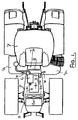
- FIG. 1 shows a typical tractor 1 which has an engine bay 2 in which is diagrammatically shown a cooling package 3 for an engine 4.
- the cooling package 3 includes a core heater/radiator assembly 3a with a cooling fan 3b. Ambient air is sucked by fan 3b through the heater/radiator assembly 3a and thereby heated up. The air is then passed over engine 4 and especially hot components like turbocharger 5 or the exhaust ducting 6. Due to hot surface temperatures (turbocharger 5 at a level of about 700 °C. exhaust ducting 6 at about 300°C) the air passing the engine (shown by arrows X) is enormously heated up, so air temperatures of up to 250°C occur.
- a heat shield part shown diagrammatically at 8 is provided to guide the air out of the engine bay 2 before impacting on the front 7a of the cab 7.
- the air is routed nearly sideways, as shown by arrows W.
- fluids such as diesel fuel or urea based fluids for exhaust treatment which are traditionally stored in tanks systems 9a and 9b on both sides of the tractor.
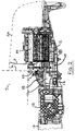
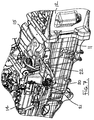
- a tractor in accordance with the present invention has a chassis 10 (see Figure 2 ) constructed from a number of cast components.
- the chassis comprises a front portion 11, a central transmission housing 12 and a rear back axle housing 13 (shown diagrammatically) which are bolted together to form the complete chassis.
- the tractor engine 4 is mounted on the front portion 11 of the chassis which is basically U-shaped in cross section leaving, to the rear of the engine, an opened topped section 11a of the chassis in which, in accordance with the present invention, a storage tank 15 for storing a urea based fluid for injecting into the engine exhaust gases is located.
- the engine is covered by an engine bonnet 2a and the heat shield 8 protects the front portion 7a of the cab from the hot air which has passed over the engine and other hot components such as the turbocharger 5 and the exhaust ducting 6.
- the engine 4 is connected with the tractor transmission within housing 12 by a drive shaft 16 which extends through the open topped section 11a of the chassis.
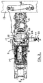
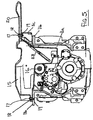
- Figures 2 , 4 and 5 show that the storage tank 15 is shaped around the drive shaft 16.
- the tank is secured to flanges 11b of the chassis by screws 17 which extend through strengthening inserts 18 in the tank to engage holes 19 in the flanges 11b or a bracket 11c carried by flanges 11b.
- the tank has a filler neck 20 closed by a cap 21.
- Filler neck 20 is provided a portion 22 of the tank 15 which extends outside the chassis 11, for example in the vicinity of the steps in to the cab of the tractor, in order to provide easy access for the filling of the tank.
- the upper portion of the tank also includes a unit 23 which includes an outlet for the stored fluid and a level sensor to provide an indication as to the amount of fluid remaining in the storage tank 15.
- the tank is well shielded from hot air which has passed over the engine by shield 8 and, being at least partially within the chassis, is also protected from the heating effects of the sun.
- the urea based fluid stored in the tank 15 is able to be maintained below the 60°C preferred level either without requiring cooling or with a significantly reduced cooling requirement.
- the precise shape of the storage tank 15 depends on the other components which may pass through or be housed within the open top section 11a of the chassis. Since the tank is preferably formed from plastics material using a moulding process its shape can be carefully tailored to provide the maximum storage volume within the free space in the section 11a of the chassis. The tank may be partially within the chassis as described above or may be entirely within the chassis if the layout of the tractor permits this.
Landscapes
- Engineering & Computer Science (AREA)
- Chemical & Material Sciences (AREA)
- Chemical Kinetics & Catalysis (AREA)
- Combustion & Propulsion (AREA)
- Mechanical Engineering (AREA)
- Health & Medical Sciences (AREA)
- Toxicology (AREA)
- General Engineering & Computer Science (AREA)
- Transportation (AREA)
- Exhaust Gas After Treatment (AREA)
Claims (4)
- Traktor (1) mit einem Chassis (10), welches in Richtung seiner Front einen Motor (4) trägt, wobei ein Ablenkschild (8) hinter dem Motor (4) angeordnet ist, um über den Motor geströmte heiße Luft seitlich abzulenken, und mit einem Tank (15) zum Aufbewahren eines harnstoffbasierten Fluids zum Einspritzen in ein Abgassystem des Motors, wobei der Tank (15) hinter dem Motor (4) und hinter dem Ablenkschild (8) angeordnet ist und wobei das Chassis (10) in Richtung hinter dem Motor (4) einen nach oben offenen Bereich zwischen dem Motor (4) und einem Getriebegehäuse (12) besitzt und der Tank (15) mindestens teilweise in dem nach oben offenen Bereich des Chassis angeordnet ist.
- Traktor nach Anspruch 1, wobei der Tank (15) eine Kunststoffspritzgusskonstruktion ist und einen oberen Bereich besitzt, der einen Einfüllstutzen (20) aufweist, der für einen einfachen Zugang außerhalb des Chassis (10) angeordnet ist.
- Traktor nach Anspruch 1 oder 2, wobei der Tank (15) um andere Komponenten herum geformt bzw. gespritzt ist, wobei sich die anderen Komponenten innerhalb des nach oben offenen Bereichs des Chassis (10) befinden.
- Traktor nach einem der Ansprüche 1 bis 3, wobei der obere Bereich des Tanks (15) einen Auslass für das aufbewahrte Fluid aufweist und eine Füllstandsanzeige für das Fluid trägt.
Applications Claiming Priority (2)
| Application Number | Priority Date | Filing Date | Title |
|---|---|---|---|
| GBGB0913581.5A GB0913581D0 (en) | 2009-08-05 | 2009-08-05 | Tractors |
| PCT/EP2010/060611 WO2011015458A1 (en) | 2009-08-05 | 2010-07-22 | Tractors |
Publications (2)
| Publication Number | Publication Date |
|---|---|
| EP2461998A1 EP2461998A1 (de) | 2012-06-13 |
| EP2461998B1 true EP2461998B1 (de) | 2016-02-10 |
Family
ID=41129608
Family Applications (1)
| Application Number | Title | Priority Date | Filing Date |
|---|---|---|---|
| EP10740191.1A Not-in-force EP2461998B1 (de) | 2009-08-05 | 2010-07-22 | Traktoren |
Country Status (4)
| Country | Link |
|---|---|
| US (1) | US8833501B2 (de) |
| EP (1) | EP2461998B1 (de) |
| GB (1) | GB0913581D0 (de) |
| WO (1) | WO2011015458A1 (de) |
Families Citing this family (4)
| Publication number | Priority date | Publication date | Assignee | Title |
|---|---|---|---|---|
| GB2466277A (en) * | 2008-12-19 | 2010-06-23 | Agco Gmbh | Exhaust systems for vehicles |
| JP5336647B1 (ja) * | 2012-12-20 | 2013-11-06 | 株式会社小松製作所 | 作業車両 |
| JP5336648B1 (ja) * | 2012-12-20 | 2013-11-06 | 株式会社小松製作所 | モータグレーダ |
| JP5956373B2 (ja) | 2013-03-28 | 2016-07-27 | ヤンマー株式会社 | 作業車両のエンジン装置 |
Family Cites Families (28)
| Publication number | Priority date | Publication date | Assignee | Title |
|---|---|---|---|---|
| DE876813C (de) | 1941-05-09 | 1953-05-18 | Suedwerke Motoren Und Kraftwag | Kuehlluftfuehrung fuer den im Vorderteil eines Kraftfahrzeuges angeordneten Antriebsmotor |
| JPS5970263A (ja) | 1982-10-16 | 1984-04-20 | Yanmar Diesel Engine Co Ltd | 農用トラクタ−の熱風遮閉装置 |
| JPS6167677A (ja) | 1984-09-10 | 1986-04-07 | Iseki & Co Ltd | 農用牽引車 |
| JPH0466328A (ja) | 1990-07-05 | 1992-03-02 | Kubota Corp | 作業車のエンジンルーム構造 |
| EP0646485B1 (de) | 1993-09-30 | 1998-05-20 | Caterpillar Inc. | Kühlkreis mit unabhängigem Leitungsystem |
| US6063350A (en) * | 1997-04-02 | 2000-05-16 | Clean Diesel Technologies, Inc. | Reducing nox emissions from an engine by temperature-controlled urea injection for selective catalytic reduction |
| DE19818448A1 (de) * | 1998-04-24 | 1999-10-28 | Siemens Ag | Verfahren und Vorrichtung zur katalytischen Reduzierung von Stickoxiden im Abgas einer Verbrennungsanlage |
| DE19843423A1 (de) * | 1998-09-22 | 2000-03-30 | Siemens Ag | Verfahren und Vorrichtung zur katalytischen Beseitigung eines Schadstoffes aus dem Abgas einer Verbrennungsanlage |
| US6941746B2 (en) * | 2002-11-21 | 2005-09-13 | Combustion Components Associates, Inc. | Mobile diesel selective catalytic reduction systems and methods |
| DE10305057A1 (de) * | 2003-02-07 | 2004-08-19 | Daimlerchrysler Ag | Abgasnachbehandlungssystem und Nutzfahrzeug mit Abgasnachbehandlungssystem |
| EP2013051A4 (de) | 2006-04-27 | 2011-03-23 | Volvo Lastvagnar Ab | Flüssigkeitsbehälter für ein fahrzeug |
| EP2172626A4 (de) * | 2007-06-26 | 2011-12-28 | Hitachi Construction Machinery | Selbstangetriebene baumaschine |
| JP5173308B2 (ja) * | 2007-07-31 | 2013-04-03 | 日野自動車株式会社 | 排気浄化装置 |
| JP4900163B2 (ja) * | 2007-09-26 | 2012-03-21 | コベルコ建機株式会社 | 建設機械 |
| US8056671B2 (en) * | 2007-10-12 | 2011-11-15 | Mazda Motor Corporation | Exhaust-gas purification device disposition structure of vehicle |
| JP2009138526A (ja) | 2007-12-03 | 2009-06-25 | Hitachi Constr Mach Co Ltd | 建設機械 |
| JP4928474B2 (ja) * | 2008-01-08 | 2012-05-09 | 日立建機株式会社 | 建設機械のNOx低減装置の配設構造 |
| JP5101324B2 (ja) * | 2008-02-07 | 2012-12-19 | 日立建機株式会社 | 建設機械のNOx低減装置の配設構造 |
| DE102008011329A1 (de) * | 2008-02-27 | 2009-09-10 | Bombardier Transportation Gmbh | Schienenfahrzeug mit Abgasreinigung |
| US8459013B2 (en) * | 2008-12-30 | 2013-06-11 | Daimler Trucks North America Llc | Urea tank with closure member for vehicle exhaust system |
| CN102803910A (zh) * | 2009-06-26 | 2012-11-28 | 施拉德尔电子学有限公司 | 使用emf波传播的液体液面和质量感测设备、系统和方法 |
| US8413431B2 (en) * | 2009-06-30 | 2013-04-09 | Eaton Corporation | Tank assembly |
| JP5402451B2 (ja) * | 2009-09-17 | 2014-01-29 | コベルコ建機株式会社 | 建設機械 |
| US8327623B2 (en) * | 2009-12-23 | 2012-12-11 | General Electric Company | Method and system for utilization of regenerative braking electrical energy for operating auxiliary system in an off-highway vehicle |
| JP2011247232A (ja) * | 2010-05-31 | 2011-12-08 | Caterpillar Sarl | 作業機械 |
| JP5356341B2 (ja) * | 2010-09-16 | 2013-12-04 | 日立建機株式会社 | 建設機械 |
| JP5562777B2 (ja) * | 2010-09-16 | 2014-07-30 | 日立建機株式会社 | 建設機械 |
| JP5649463B2 (ja) * | 2011-01-14 | 2015-01-07 | 日立建機株式会社 | 建設機械 |
-
2009
- 2009-08-05 GB GBGB0913581.5A patent/GB0913581D0/en not_active Ceased
-
2010
- 2010-07-22 US US13/389,035 patent/US8833501B2/en active Active
- 2010-07-22 EP EP10740191.1A patent/EP2461998B1/de not_active Not-in-force
- 2010-07-22 WO PCT/EP2010/060611 patent/WO2011015458A1/en not_active Ceased
Also Published As
| Publication number | Publication date |
|---|---|
| US8833501B2 (en) | 2014-09-16 |
| WO2011015458A1 (en) | 2011-02-10 |
| GB0913581D0 (en) | 2009-09-16 |
| US20120217082A1 (en) | 2012-08-30 |
| EP2461998A1 (de) | 2012-06-13 |
Similar Documents
| Publication | Publication Date | Title |
|---|---|---|
| EP2461998B1 (de) | Traktoren | |
| EP2268905B1 (de) | Fahrzeugabgasbehandlungssysteme | |
| JP5108770B2 (ja) | 液状の還元剤、殊に尿素溶剤のための車両タンク | |
| EP2320047B1 (de) | Kühlstruktur für einen superlader | |
| CN103538463B (zh) | 多功能冷却系统 | |
| JP6448507B2 (ja) | 作業車両 | |
| US8961660B2 (en) | Canister arrangement structure, fuel vapor recovery device, and vehicle equipped with fuel vapor recovery device | |
| JPH0988587A (ja) | エンジンルーム内の吸気冷却構造 | |
| EP3663549B1 (de) | Nutzfahrzeug | |
| EP2865552A1 (de) | Nutzfahrzeug | |
| US9636998B1 (en) | Tank enclosure with fan | |
| US9096121B2 (en) | Cool air plenum | |
| EP2650528B1 (de) | Motorrad | |
| US9834088B2 (en) | Work vehicle | |
| CN202722038U (zh) | 联合收割机的驾驶部结构 | |
| JP6809798B2 (ja) | エンジン | |
| CN104827891B (zh) | 驱动轴胶套冷却装置 | |
| JP2014177765A (ja) | ボンネット付車両 | |
| JP3334429B2 (ja) | V型内燃機関における燃料系部品の取付装置 | |
| JP4622491B2 (ja) | 自動車のカウル部熱害防止構造 | |
| JP2005282488A (ja) | 車両用エンジンの吸気装置 | |
| JP2005273511A (ja) | 車両用エンジンの吸気温度低減装置 | |
| JP6616646B2 (ja) | 自動二輪車のエンジンの吸気系の遮熱構造 | |
| BRPI1106598B1 (pt) | Tanque de combustível de veículo agrícola disposto sobre o motor |
Legal Events
| Date | Code | Title | Description |
|---|---|---|---|
| PUAI | Public reference made under article 153(3) epc to a published international application that has entered the european phase |
Free format text: ORIGINAL CODE: 0009012 |
|
| 17P | Request for examination filed |
Effective date: 20120305 |
|
| AK | Designated contracting states |
Kind code of ref document: A1 Designated state(s): AL AT BE BG CH CY CZ DE DK EE ES FI FR GB GR HR HU IE IS IT LI LT LU LV MC MK MT NL NO PL PT RO SE SI SK SM TR |
|
| DAX | Request for extension of the european patent (deleted) | ||
| GRAP | Despatch of communication of intention to grant a patent |
Free format text: ORIGINAL CODE: EPIDOSNIGR1 |
|
| INTG | Intention to grant announced |
Effective date: 20151002 |
|
| GRAS | Grant fee paid |
Free format text: ORIGINAL CODE: EPIDOSNIGR3 |
|
| GRAA | (expected) grant |
Free format text: ORIGINAL CODE: 0009210 |
|
| AK | Designated contracting states |
Kind code of ref document: B1 Designated state(s): AL AT BE BG CH CY CZ DE DK EE ES FI FR GB GR HR HU IE IS IT LI LT LU LV MC MK MT NL NO PL PT RO SE SI SK SM TR |
|
| REG | Reference to a national code |
Ref country code: GB Ref legal event code: FG4D |
|
| REG | Reference to a national code |
Ref country code: AT Ref legal event code: REF Ref document number: 774472 Country of ref document: AT Kind code of ref document: T Effective date: 20160215 Ref country code: CH Ref legal event code: EP |
|
| REG | Reference to a national code |
Ref country code: IE Ref legal event code: FG4D |
|
| REG | Reference to a national code |
Ref country code: DE Ref legal event code: R096 Ref document number: 602010030555 Country of ref document: DE |
|
| REG | Reference to a national code |
Ref country code: LT Ref legal event code: MG4D |
|
| REG | Reference to a national code |
Ref country code: NL Ref legal event code: MP Effective date: 20160210 |
|
| REG | Reference to a national code |
Ref country code: AT Ref legal event code: MK05 Ref document number: 774472 Country of ref document: AT Kind code of ref document: T Effective date: 20160210 |
|
| REG | Reference to a national code |
Ref country code: FR Ref legal event code: PLFP Year of fee payment: 7 |
|
| PG25 | Lapsed in a contracting state [announced via postgrant information from national office to epo] |
Ref country code: GR Free format text: LAPSE BECAUSE OF FAILURE TO SUBMIT A TRANSLATION OF THE DESCRIPTION OR TO PAY THE FEE WITHIN THE PRESCRIBED TIME-LIMIT Effective date: 20160511 Ref country code: ES Free format text: LAPSE BECAUSE OF FAILURE TO SUBMIT A TRANSLATION OF THE DESCRIPTION OR TO PAY THE FEE WITHIN THE PRESCRIBED TIME-LIMIT Effective date: 20160210 Ref country code: HR Free format text: LAPSE BECAUSE OF FAILURE TO SUBMIT A TRANSLATION OF THE DESCRIPTION OR TO PAY THE FEE WITHIN THE PRESCRIBED TIME-LIMIT Effective date: 20160210 Ref country code: NO Free format text: LAPSE BECAUSE OF FAILURE TO SUBMIT A TRANSLATION OF THE DESCRIPTION OR TO PAY THE FEE WITHIN THE PRESCRIBED TIME-LIMIT Effective date: 20160510 Ref country code: FI Free format text: LAPSE BECAUSE OF FAILURE TO SUBMIT A TRANSLATION OF THE DESCRIPTION OR TO PAY THE FEE WITHIN THE PRESCRIBED TIME-LIMIT Effective date: 20160210 |
|
| PG25 | Lapsed in a contracting state [announced via postgrant information from national office to epo] |
Ref country code: SE Free format text: LAPSE BECAUSE OF FAILURE TO SUBMIT A TRANSLATION OF THE DESCRIPTION OR TO PAY THE FEE WITHIN THE PRESCRIBED TIME-LIMIT Effective date: 20160210 Ref country code: IS Free format text: LAPSE BECAUSE OF FAILURE TO SUBMIT A TRANSLATION OF THE DESCRIPTION OR TO PAY THE FEE WITHIN THE PRESCRIBED TIME-LIMIT Effective date: 20160610 Ref country code: LV Free format text: LAPSE BECAUSE OF FAILURE TO SUBMIT A TRANSLATION OF THE DESCRIPTION OR TO PAY THE FEE WITHIN THE PRESCRIBED TIME-LIMIT Effective date: 20160210 Ref country code: PL Free format text: LAPSE BECAUSE OF FAILURE TO SUBMIT A TRANSLATION OF THE DESCRIPTION OR TO PAY THE FEE WITHIN THE PRESCRIBED TIME-LIMIT Effective date: 20160210 Ref country code: LT Free format text: LAPSE BECAUSE OF FAILURE TO SUBMIT A TRANSLATION OF THE DESCRIPTION OR TO PAY THE FEE WITHIN THE PRESCRIBED TIME-LIMIT Effective date: 20160210 Ref country code: PT Free format text: LAPSE BECAUSE OF FAILURE TO SUBMIT A TRANSLATION OF THE DESCRIPTION OR TO PAY THE FEE WITHIN THE PRESCRIBED TIME-LIMIT Effective date: 20160613 Ref country code: NL Free format text: LAPSE BECAUSE OF FAILURE TO SUBMIT A TRANSLATION OF THE DESCRIPTION OR TO PAY THE FEE WITHIN THE PRESCRIBED TIME-LIMIT Effective date: 20160210 Ref country code: AT Free format text: LAPSE BECAUSE OF FAILURE TO SUBMIT A TRANSLATION OF THE DESCRIPTION OR TO PAY THE FEE WITHIN THE PRESCRIBED TIME-LIMIT Effective date: 20160210 |
|
| PG25 | Lapsed in a contracting state [announced via postgrant information from national office to epo] |
Ref country code: EE Free format text: LAPSE BECAUSE OF FAILURE TO SUBMIT A TRANSLATION OF THE DESCRIPTION OR TO PAY THE FEE WITHIN THE PRESCRIBED TIME-LIMIT Effective date: 20160210 Ref country code: DK Free format text: LAPSE BECAUSE OF FAILURE TO SUBMIT A TRANSLATION OF THE DESCRIPTION OR TO PAY THE FEE WITHIN THE PRESCRIBED TIME-LIMIT Effective date: 20160210 |
|
| REG | Reference to a national code |
Ref country code: DE Ref legal event code: R097 Ref document number: 602010030555 Country of ref document: DE |
|
| PG25 | Lapsed in a contracting state [announced via postgrant information from national office to epo] |
Ref country code: SM Free format text: LAPSE BECAUSE OF FAILURE TO SUBMIT A TRANSLATION OF THE DESCRIPTION OR TO PAY THE FEE WITHIN THE PRESCRIBED TIME-LIMIT Effective date: 20160210 Ref country code: SK Free format text: LAPSE BECAUSE OF FAILURE TO SUBMIT A TRANSLATION OF THE DESCRIPTION OR TO PAY THE FEE WITHIN THE PRESCRIBED TIME-LIMIT Effective date: 20160210 Ref country code: CZ Free format text: LAPSE BECAUSE OF FAILURE TO SUBMIT A TRANSLATION OF THE DESCRIPTION OR TO PAY THE FEE WITHIN THE PRESCRIBED TIME-LIMIT Effective date: 20160210 Ref country code: RO Free format text: LAPSE BECAUSE OF FAILURE TO SUBMIT A TRANSLATION OF THE DESCRIPTION OR TO PAY THE FEE WITHIN THE PRESCRIBED TIME-LIMIT Effective date: 20160210 |
|
| PLBE | No opposition filed within time limit |
Free format text: ORIGINAL CODE: 0009261 |
|
| STAA | Information on the status of an ep patent application or granted ep patent |
Free format text: STATUS: NO OPPOSITION FILED WITHIN TIME LIMIT |
|
| PG25 | Lapsed in a contracting state [announced via postgrant information from national office to epo] |
Ref country code: BE Free format text: LAPSE BECAUSE OF FAILURE TO SUBMIT A TRANSLATION OF THE DESCRIPTION OR TO PAY THE FEE WITHIN THE PRESCRIBED TIME-LIMIT Effective date: 20160210 |
|
| 26N | No opposition filed |
Effective date: 20161111 |
|
| PG25 | Lapsed in a contracting state [announced via postgrant information from national office to epo] |
Ref country code: SI Free format text: LAPSE BECAUSE OF FAILURE TO SUBMIT A TRANSLATION OF THE DESCRIPTION OR TO PAY THE FEE WITHIN THE PRESCRIBED TIME-LIMIT Effective date: 20160210 Ref country code: BG Free format text: LAPSE BECAUSE OF FAILURE TO SUBMIT A TRANSLATION OF THE DESCRIPTION OR TO PAY THE FEE WITHIN THE PRESCRIBED TIME-LIMIT Effective date: 20160510 |
|
| REG | Reference to a national code |
Ref country code: CH Ref legal event code: PL |
|
| GBPC | Gb: european patent ceased through non-payment of renewal fee |
Effective date: 20160722 |
|
| PG25 | Lapsed in a contracting state [announced via postgrant information from national office to epo] |
Ref country code: MC Free format text: LAPSE BECAUSE OF FAILURE TO SUBMIT A TRANSLATION OF THE DESCRIPTION OR TO PAY THE FEE WITHIN THE PRESCRIBED TIME-LIMIT Effective date: 20160210 |
|
| PG25 | Lapsed in a contracting state [announced via postgrant information from national office to epo] |
Ref country code: CH Free format text: LAPSE BECAUSE OF NON-PAYMENT OF DUE FEES Effective date: 20160731 Ref country code: LI Free format text: LAPSE BECAUSE OF NON-PAYMENT OF DUE FEES Effective date: 20160731 |
|
| REG | Reference to a national code |
Ref country code: IE Ref legal event code: MM4A |
|
| PG25 | Lapsed in a contracting state [announced via postgrant information from national office to epo] |
Ref country code: GB Free format text: LAPSE BECAUSE OF NON-PAYMENT OF DUE FEES Effective date: 20160722 |
|
| REG | Reference to a national code |
Ref country code: FR Ref legal event code: PLFP Year of fee payment: 8 |
|
| PG25 | Lapsed in a contracting state [announced via postgrant information from national office to epo] |
Ref country code: IE Free format text: LAPSE BECAUSE OF NON-PAYMENT OF DUE FEES Effective date: 20160722 |
|
| PG25 | Lapsed in a contracting state [announced via postgrant information from national office to epo] |
Ref country code: LU Free format text: LAPSE BECAUSE OF NON-PAYMENT OF DUE FEES Effective date: 20160722 |
|
| PG25 | Lapsed in a contracting state [announced via postgrant information from national office to epo] |
Ref country code: HU Free format text: LAPSE BECAUSE OF FAILURE TO SUBMIT A TRANSLATION OF THE DESCRIPTION OR TO PAY THE FEE WITHIN THE PRESCRIBED TIME-LIMIT; INVALID AB INITIO Effective date: 20100722 Ref country code: CY Free format text: LAPSE BECAUSE OF FAILURE TO SUBMIT A TRANSLATION OF THE DESCRIPTION OR TO PAY THE FEE WITHIN THE PRESCRIBED TIME-LIMIT Effective date: 20160210 |
|
| PG25 | Lapsed in a contracting state [announced via postgrant information from national office to epo] |
Ref country code: TR Free format text: LAPSE BECAUSE OF FAILURE TO SUBMIT A TRANSLATION OF THE DESCRIPTION OR TO PAY THE FEE WITHIN THE PRESCRIBED TIME-LIMIT Effective date: 20160210 Ref country code: MT Free format text: LAPSE BECAUSE OF NON-PAYMENT OF DUE FEES Effective date: 20160731 Ref country code: MK Free format text: LAPSE BECAUSE OF FAILURE TO SUBMIT A TRANSLATION OF THE DESCRIPTION OR TO PAY THE FEE WITHIN THE PRESCRIBED TIME-LIMIT Effective date: 20160210 |
|
| REG | Reference to a national code |
Ref country code: FR Ref legal event code: PLFP Year of fee payment: 9 |
|
| PG25 | Lapsed in a contracting state [announced via postgrant information from national office to epo] |
Ref country code: AL Free format text: LAPSE BECAUSE OF FAILURE TO SUBMIT A TRANSLATION OF THE DESCRIPTION OR TO PAY THE FEE WITHIN THE PRESCRIBED TIME-LIMIT Effective date: 20160210 |
|
| PGFP | Annual fee paid to national office [announced via postgrant information from national office to epo] |
Ref country code: IT Payment date: 20180719 Year of fee payment: 9 |
|
| PG25 | Lapsed in a contracting state [announced via postgrant information from national office to epo] |
Ref country code: IT Free format text: LAPSE BECAUSE OF NON-PAYMENT OF DUE FEES Effective date: 20190722 |
|
| PGFP | Annual fee paid to national office [announced via postgrant information from national office to epo] |
Ref country code: DE Payment date: 20220620 Year of fee payment: 13 |
|
| PGFP | Annual fee paid to national office [announced via postgrant information from national office to epo] |
Ref country code: FR Payment date: 20220720 Year of fee payment: 13 |
|
| P01 | Opt-out of the competence of the unified patent court (upc) registered |
Effective date: 20230518 |
|
| REG | Reference to a national code |
Ref country code: DE Ref legal event code: R119 Ref document number: 602010030555 Country of ref document: DE |
|
| PG25 | Lapsed in a contracting state [announced via postgrant information from national office to epo] |
Ref country code: DE Free format text: LAPSE BECAUSE OF NON-PAYMENT OF DUE FEES Effective date: 20240201 |
|
| PG25 | Lapsed in a contracting state [announced via postgrant information from national office to epo] |
Ref country code: FR Free format text: LAPSE BECAUSE OF NON-PAYMENT OF DUE FEES Effective date: 20230731 |