EP2460975A2 - Dispositif et procédé pour la stimulation du puits. - Google Patents
Dispositif et procédé pour la stimulation du puits. Download PDFInfo
- Publication number
- EP2460975A2 EP2460975A2 EP20110191467 EP11191467A EP2460975A2 EP 2460975 A2 EP2460975 A2 EP 2460975A2 EP 20110191467 EP20110191467 EP 20110191467 EP 11191467 A EP11191467 A EP 11191467A EP 2460975 A2 EP2460975 A2 EP 2460975A2
- Authority
- EP
- European Patent Office
- Prior art keywords
- charge
- sleeves
- sleeve
- limiting element
- limiting
- Prior art date
- Legal status (The legal status is an assumption and is not a legal conclusion. Google has not performed a legal analysis and makes no representation as to the accuracy of the status listed.)
- Withdrawn
Links
- 238000000034 method Methods 0.000 title claims abstract description 31
- 230000000638 stimulation Effects 0.000 title claims abstract description 13
- 230000015572 biosynthetic process Effects 0.000 title description 4
- 230000000670 limiting effect Effects 0.000 claims abstract description 111
- 239000004449 solid propellant Substances 0.000 claims description 36
- 239000011435 rock Substances 0.000 claims description 21
- 239000000463 material Substances 0.000 claims description 20
- 239000007788 liquid Substances 0.000 claims description 19
- 238000005192 partition Methods 0.000 claims description 14
- 239000007787 solid Substances 0.000 claims description 14
- 238000012856 packing Methods 0.000 claims description 12
- 230000035699 permeability Effects 0.000 claims description 11
- 230000009969 flowable effect Effects 0.000 claims description 7
- 230000002829 reductive effect Effects 0.000 claims description 6
- 238000010304 firing Methods 0.000 claims description 2
- 239000007789 gas Substances 0.000 description 108
- 229910000831 Steel Inorganic materials 0.000 description 15
- 239000010959 steel Substances 0.000 description 15
- 239000002360 explosive Substances 0.000 description 12
- 230000008569 process Effects 0.000 description 12
- XLYOFNOQVPJJNP-UHFFFAOYSA-N water Substances O XLYOFNOQVPJJNP-UHFFFAOYSA-N 0.000 description 11
- 238000004519 manufacturing process Methods 0.000 description 10
- 238000007789 sealing Methods 0.000 description 10
- 238000011161 development Methods 0.000 description 8
- VNWKTOKETHGBQD-UHFFFAOYSA-N methane Chemical compound C VNWKTOKETHGBQD-UHFFFAOYSA-N 0.000 description 6
- 230000000694 effects Effects 0.000 description 5
- 230000008901 benefit Effects 0.000 description 4
- 230000006378 damage Effects 0.000 description 4
- 238000013461 design Methods 0.000 description 4
- 239000012530 fluid Substances 0.000 description 4
- 239000000203 mixture Substances 0.000 description 4
- 239000004033 plastic Substances 0.000 description 4
- 229920003023 plastic Polymers 0.000 description 4
- -1 aromatic amino acid Chemical class 0.000 description 3
- 238000010276 construction Methods 0.000 description 3
- 230000001419 dependent effect Effects 0.000 description 3
- 239000000446 fuel Substances 0.000 description 3
- 239000003345 natural gas Substances 0.000 description 3
- 230000001681 protective effect Effects 0.000 description 3
- 239000000126 substance Substances 0.000 description 3
- 239000000725 suspension Substances 0.000 description 3
- NLXLAEXVIDQMFP-UHFFFAOYSA-N Ammonia chloride Chemical group [NH4+].[Cl-] NLXLAEXVIDQMFP-UHFFFAOYSA-N 0.000 description 2
- VEXZGXHMUGYJMC-UHFFFAOYSA-N Hydrochloric acid Chemical compound Cl VEXZGXHMUGYJMC-UHFFFAOYSA-N 0.000 description 2
- 230000007423 decrease Effects 0.000 description 2
- 229920001971 elastomer Polymers 0.000 description 2
- 238000005516 engineering process Methods 0.000 description 2
- 230000006872 improvement Effects 0.000 description 2
- 238000002347 injection Methods 0.000 description 2
- 239000007924 injection Substances 0.000 description 2
- 229910052751 metal Inorganic materials 0.000 description 2
- 239000002184 metal Substances 0.000 description 2
- 239000000843 powder Substances 0.000 description 2
- 230000010349 pulsation Effects 0.000 description 2
- 230000009467 reduction Effects 0.000 description 2
- 239000005060 rubber Substances 0.000 description 2
- 239000004576 sand Substances 0.000 description 2
- PAWQVTBBRAZDMG-UHFFFAOYSA-N 2-(3-bromo-2-fluorophenyl)acetic acid Chemical compound OC(=O)CC1=CC=CC(Br)=C1F PAWQVTBBRAZDMG-UHFFFAOYSA-N 0.000 description 1
- GDDNTTHUKVNJRA-UHFFFAOYSA-N 3-bromo-3,3-difluoroprop-1-ene Chemical compound FC(F)(Br)C=C GDDNTTHUKVNJRA-UHFFFAOYSA-N 0.000 description 1
- 239000004451 Ballistite Substances 0.000 description 1
- OKTJSMMVPCPJKN-UHFFFAOYSA-N Carbon Chemical compound [C] OKTJSMMVPCPJKN-UHFFFAOYSA-N 0.000 description 1
- 239000004593 Epoxy Substances 0.000 description 1
- 239000004952 Polyamide Substances 0.000 description 1
- 239000004698 Polyethylene Substances 0.000 description 1
- 239000004743 Polypropylene Substances 0.000 description 1
- RTAQQCXQSZGOHL-UHFFFAOYSA-N Titanium Chemical compound [Ti] RTAQQCXQSZGOHL-UHFFFAOYSA-N 0.000 description 1
- 239000013543 active substance Substances 0.000 description 1
- 230000002411 adverse Effects 0.000 description 1
- XAGFODPZIPBFFR-UHFFFAOYSA-N aluminium Chemical compound [Al] XAGFODPZIPBFFR-UHFFFAOYSA-N 0.000 description 1
- 235000019270 ammonium chloride Nutrition 0.000 description 1
- 239000007864 aqueous solution Substances 0.000 description 1
- 150000004982 aromatic amines Chemical class 0.000 description 1
- 239000003054 catalyst Substances 0.000 description 1
- 238000005253 cladding Methods 0.000 description 1
- 230000006835 compression Effects 0.000 description 1
- 238000007906 compression Methods 0.000 description 1
- 239000000470 constituent Substances 0.000 description 1
- 230000003247 decreasing effect Effects 0.000 description 1
- 238000005553 drilling Methods 0.000 description 1
- 238000010891 electric arc Methods 0.000 description 1
- 238000000605 extraction Methods 0.000 description 1
- 239000008398 formation water Substances 0.000 description 1
- 238000010438 heat treatment Methods 0.000 description 1
- 230000002706 hydrostatic effect Effects 0.000 description 1
- BDAGIHXWWSANSR-NJFSPNSNSA-N hydroxyformaldehyde Chemical compound O[14CH]=O BDAGIHXWWSANSR-NJFSPNSNSA-N 0.000 description 1
- 238000003780 insertion Methods 0.000 description 1
- 230000037431 insertion Effects 0.000 description 1
- 238000009413 insulation Methods 0.000 description 1
- 229920003049 isoprene rubber Polymers 0.000 description 1
- 239000003607 modifier Substances 0.000 description 1
- 230000010355 oscillation Effects 0.000 description 1
- 239000012188 paraffin wax Substances 0.000 description 1
- 239000003208 petroleum Substances 0.000 description 1
- 239000003209 petroleum derivative Substances 0.000 description 1
- 239000002985 plastic film Substances 0.000 description 1
- 229920006255 plastic film Polymers 0.000 description 1
- 229920003229 poly(methyl methacrylate) Polymers 0.000 description 1
- 229920002647 polyamide Polymers 0.000 description 1
- 229920000573 polyethylene Polymers 0.000 description 1
- 239000004926 polymethyl methacrylate Substances 0.000 description 1
- 229920001155 polypropylene Polymers 0.000 description 1
- 230000008092 positive effect Effects 0.000 description 1
- 230000005855 radiation Effects 0.000 description 1
- 239000011343 solid material Substances 0.000 description 1
- 229910000018 strontium carbonate Inorganic materials 0.000 description 1
- 239000011269 tar Substances 0.000 description 1
- 239000010936 titanium Substances 0.000 description 1
- 229910052719 titanium Inorganic materials 0.000 description 1
- 229920002554 vinyl polymer Polymers 0.000 description 1
- 239000003643 water by type Substances 0.000 description 1
- 238000003466 welding Methods 0.000 description 1
- 238000004804 winding Methods 0.000 description 1
Images


Classifications
-
- E—FIXED CONSTRUCTIONS
- E21—EARTH OR ROCK DRILLING; MINING
- E21B—EARTH OR ROCK DRILLING; OBTAINING OIL, GAS, WATER, SOLUBLE OR MELTABLE MATERIALS OR A SLURRY OF MINERALS FROM WELLS
- E21B43/00—Methods or apparatus for obtaining oil, gas, water, soluble or meltable materials or a slurry of minerals from wells
- E21B43/11—Perforators; Permeators
- E21B43/116—Gun or shaped-charge perforators
Definitions
- the present invention relates to a device for well stimulation comprising a support element with a first limiting element and a second limiting element, furthermore at least one charge packet containing one or more charge units of a solid fuel, and further at least one igniter for igniting the at least one charge packet, wherein the charge packet or the charge packets are or are arranged on the support element between the delimiting elements. Furthermore, the invention relates to a method for borehole stimulation using the device according to the invention.
- the porous rock strata may silt during the drilling and cementing process, decreasing permeability.
- the state of stress, pressure and deformation of the rock changes, resulting in zones with increased density and low permeability forming around the hole in a circular manner in the rock.
- paraffin, asphaltenes and high viscosity tars often deposit in the rock, reducing the productivity of the well.
- perforation technology uses gas generators powered by solid fuels. They are designed as jacketed or uncovered explosive charges and produce hot gases after ignition, resulting in a pressure increase in the borehole and the adjacent rock layers. Usually gas generators are used in the borehole at the level of winninghorizonte to cause due to the pressure increase new perforations in the rock or to expand existing perforations.
- the device includes tubular cylindrical explosive charges, ignition charges and a geophysical cable, a so-called logging cable, with explosive charge fasteners.
- the cable can be inside a winding cable, so that the gas generator can also be used for angled, directed and horizontal holes.
- burning the cylindrical explosive charges in the bore carried a thermo-chemical treatment and air pressure treatment of the rock. If a perforation has been carried out in advance, the perforation channels are widened and cleaned, and fine cracks are formed in the rock. At high pressure of the gas generators these processes are amplified. Under certain circumstances, extensive cracks may form.
- a disadvantage of this method is that the escaping gases spread quickly in the well and consequently the amount of energy available in the area of the well to be treated is relatively small.
- the patents RU 2176728 C1 such as RU 2151282 C1 reveal gas generators that run on solid fuels. These gas generators consist of tubular explosive charges or explosive charges with longitudinal channels. Here, the length of the explosive charge and the diameter of the longitudinal channel depends on a certain ratio, which determines the pulsation of the pressure of the gases when burning the explosive charges.
- US 2008/0271894 A1 discloses an apparatus and method for creating perforations in subterranean rock layers.
- a carrier explosive charges are mounted, which produce perforations in the adjacent rock after ignition and expand by increasing the pressure.
- the device is provided with sealing elements which deform with increasing pressure such that they rest against the borehole wall and thereby limit the space of pressure development.
- the object was to provide a device and a method for well stimulation by means of which the permeability of the rock around a region of the well can be targeted and efficiently improved.
- the device should be simple in construction and inexpensive to manufacture.
- the gas generator comprises a support element which is designed as a rod or rope.
- the support element is made of a highly resistant material that is not destroyed when burning the charge packets in the borehole.
- the support element is made of steel, preferably of high-strength toughened steel.
- the support element may be surrounded by a protective cover, in particular if the support element is designed as a dew.
- the protective cover is preferably made of a highly resistant material, particularly preferably of a high-strength steel. The protective cover prevents the support element from being damaged during the burning of the charge packets. It can be easily replaced if necessary.
- the support element is designed as a hollow rod or tube with a continuous axial channel.
- a first limiting element and a second limiting element are mounted according to the invention. They are also made of a material that is not destroyed when burning the charge packets.
- the limiting elements are made of steel, in particular high-strength tough steel.
- the limiting elements are preferably configured as disks with a central axial bore through which the support element can be guided. A simple to produce variant of the limiting elements are massive steel discs.
- the limiting elements are firmly connected to the support member, for example by means of fasteners such as mechanical brackets, clamps or screw.
- the delimiting elements have, in the axial direction, that is to say along the carrier element, an extension which is chosen to be at least large enough that the delimiting elements are not destroyed during the burning process. This minimum expansion depends on the material properties of the limiting elements as well as the properties and the amount of fuel used.
- the expansion of the limiting elements in the axial direction is preferably from 50% to 100%, particularly preferably from 70% to 100%, in particular from 90% to 100%, of the inner diameter of the borehole in the region in which the gas generator is used.
- Such an axial extension of the limiting elements reliably prevents tilting of the limiting elements when the gas generator is introduced into the bore.
- the load units are designed as cylinders with a continuous axial recess.
- the charge units have a substantially circular cross-section.
- the diameter of the charge units is particularly preferably from 8 to 15 cm, in particular from 10 to 12 cm.
- the diameter is advantageously chosen to be 10% to 20% smaller than the inside diameter of the wellbore in the area where the gas generator is used.
- the diameter of the axial recess is preferably from 8 to 15 mm, particularly preferably from 10 to 12 mm.
- the height of the individual charge units is preferably from 5 to 140 cm.
- the total length of the charge packet or the charge packets is selected as a function of the axial extent of the perforation region of the delivery horizon and is preferably from 0.5 to 30 m.
- the charge packet is or the charge packets are arranged on the support element between the boundary elements by the support element is guided by the axial recesses of the charge units.
- the perforation region is understood here and below to mean the region of a conveying horizon in which perforation holes and perforation channels are already present or are to be produced by using the gas generator. Frequently, the axial extent of the perforation region corresponds to the thickness of the rock layer from which the fluid, e.g. Oil or natural gas, to be promoted.
- the fluid e.g. Oil or natural gas
- the gas generator according to the invention further comprises at least one igniter for igniting the at least one charge packet.
- igniter depends on the solid fuel used. Suitable detonators are known to the person skilled in the art, for example electric arc igniters or spiral igniters.
- the support element has an axial channel in the interior, through which, for example, electrical lines or other lines required for the ignition of the igniter can be guided.
- a charge packet comprises a plurality of charge units, wherein adjacent charge units have different outer diameters.
- the smaller outer diameters preferably have values in the range of 75% to 95% of the largest outside diameter.
- the axial extent of the reduced outer diameter charge units is preferably from 10% to 50% of the average axial extension of the unreduced outer diameter charge units.
- the charge units with non-reduced outer diameter each have the same axial extent.
- charge units having a smaller outer diameter are comprised of a ring cladding made of a material which is not destroyed upon burning of the charge packets.
- the annular sheaths are made of steel, in particular of high-strength tough steel.
- the annular sheaths in the same axial extent as the unit in question and in a wall thickness, which compensates for the difference in the outer radii of adjacent charge units, so that the complete charge packet over its length has substantially the same outer radius.
- the entire space between the boundary elements is filled with a charge packet in the axial direction.
- the detonator or detonators are arranged in such a way that upon ignition the burning of the charge packet begins in an axially central region and continues in the direction of the first and second limiting element.
- the gas generator comprises two charge packets, which are arranged at a distance from each other on the support element. At least one detonator is present on or in each charge packet so that the charge packets can be ignited simultaneously or one after the other. Particularly preferably, the two charge packets are substantially the same length and designed so that almost the same amounts of energy are released when burning from both sides.
- the distance between the two mutually facing ends of the charge packets is preferably at most as large as the axial extent of the perforation region in the bore.
- the gas generator further comprises at least one seal packing made of easily flowable solid and at least one additional limiting element which is mounted in the axial direction outside the space between the first limiting element and the second limiting element on the support element.
- an additional limiting element in the axial direction above the first limiting element is fixedly connected to the supporting element, and a sealing packing is arranged between the additional limiting element and the first limiting element.
- an additional limiting element in the axial direction below the second limiting element is fixedly connected to the supporting element, and a sealing pack is arranged between the additional limiting element and the second limiting element.
- Preference is given to sealing packings both at the upper end and at the lower end.
- the first limiting element and / or the second limiting element is movably mounted in the axial direction along the support element.
- the additional limiting element may be made of different materials, preferably it is made of a metal, in particular a high-strength tough steel. Its shape may correspond to that of the first or second limiting element, for example a disk with a central bore through which the support element is guided.
- the first limiting element and / or the second limiting element is designed such that its diameter on the side facing the sealing element is smaller than the diameter on the side facing the charge packet.
- the additional limiting element is designed such that its diameter on the side facing the sealing element is smaller than the diameter on the side facing outward.
- both the first and / or second limiting element and the respective additional limiting element are designed in this way. Such a configuration in the form of a truncated cone is particularly advantageous.
- the gaskets are chosen to be stable on the one hand when installed in the gas generator and during the introduction into the well, but on the other hand lose their strength when pressure builds up due to the burning of the solid fuel charges. Due to the pressure build-up, the seal packing is compressed in the axial direction, the flowable solid deviates radially to the side and forms a sealing layer that fills the entire cross section of the borehole in this area. The solid can also flow into the annular spaces around the limiting element, the charge packet and / or the additional limiting element. By choosing a solid having a high coefficient of friction, preferably pressed sand, the amount of solids flowing into the annuli can be reduced. The amount of solid that flows into the annular spaces can be further reduced by configuring the restricting element and / or the additional limiting element as described above with reduced diameter, preferably conical.
- the amount of the flowable solid is such that a sealing effect is maintained over a certain period of the burning process of the charge packets.
- the length of a packing is from 0.5 to 1.5 m.
- the outer diameter of the packing is preferably not larger than the outer diameter of the limiting elements.
- the packing may be encased, for example with a tear-resistant plastic film.
- the gas generator further comprises two sleeves, which are made of a material which is not destroyed when burning the charge packets.
- the sleeves are made of steel, in particular high-strength tough steel.
- the sleeves enclose the charge packets in the radial direction.
- the first sleeve is gas-tightly attached to one end of the first limiting element
- the second sleeve is gas-tightly attached to one end of the second limiting element.
- the other ends of the sleeves are facing each other.
- the gas-tight attachment of the sleeve ends to the respective limiting element can be done for example by a welded connection.
- the wall thickness of the sleeves is chosen so that the sleeves are not destroyed when burning the charge packets. It depends on the properties of the material from which the sleeves are made, the dimensions of the cargo packages, and the properties and quantity of solid fuel used.
- sleeves are also referred to as “housing”.
- a gas generator without sleeves is accordingly referred to as “caseless”.
- the axial extent of the first and second limiting element is preferably selected in the above-mentioned ranges.
- the limiting elements can be made smaller in contrast to their axial extent, as by the axial extent of the sleeve tilting of the gas generator in the borehole is already largely avoided.
- the axial minimum extent of the limiting elements to protect against destruction during the Abbrennvorgangs is not exceeded even with gas generators with housing.
- a continuous charge packet is arranged between the delimiting elements.
- the sleeves preferably do not completely enclose the charge packet in the axial direction. This means that there is a distance between the mutually facing ends of the sleeves. This distance is particularly preferably chosen so that it is at most as large as the axial extent of the perforation in the bore.
- the charge units, which are covered by the sleeves are selected such that their burning speed is higher than that of the charge units, which are not included in the radial direction of the sleeves.
- the gas generator comprises two charge packets, which rest on the respective limiting element and have a gap between their ends facing each other.
- the sleeves comprise the respective charge packet preferably also in the axial direction completely.
- the distance between the mutually facing ends of the two sleeves is at most as large as the axial extent of the perforation region in the bore.
- a charge packet is arranged, which bears against the respective limiting element and the sleeve only partially fills in the axial direction.
- the gas generator further comprises two pressure pistons, which are movably mounted on the support member in the axial direction.
- the pressure piston has a central axial bore through which the support element is guided.
- One end of the respective pressure piston protrudes into the open end of the corresponding sleeve, preferably the end of the pressure piston bears against the charge packet located in the sleeve.
- the other end of the respective pressure piston preferably protrudes beyond the open end of the sleeve and has an outer diameter which is greater than the inner diameter of the sleeve at its open end.
- the outer diameter of the pressure piston is also greater than the outer diameter of the sleeve at its open end, so that the pressure piston protrudes in the radial direction beyond the end of the sleeve.
- the outer diameter of the pressure piston is preferably from 80% to 95% of the inner diameter of the borehole at the point at which the gas generator is used.
- the mutually facing end faces of the pressure piston have an axial distance, which is advantageously chosen so large that it corresponds to the axial extent of the perforation in the bore. However, the distance can also be chosen to be smaller, for example in the case of extended perforation areas.
- the mutually facing end sides of the pressure piston are flat.
- the end faces are concave, so that the axial distance between the radially outer edges of the opposite end faces is less than the axial distance between their centers.
- the plungers may be made of different materials as long as they are not destroyed during the burning of the charge packets.
- the pressure piston made of a metal, in particular a high-strength tough steel.
- an igniter preferably, the igniter is attached to the end of the charge packet, which faces the plunger.
- a pressure is generated by the gas evolution, which moves the two pressure pistons toward each other.
- This type of gas generator is preferably used when there is a liquid, for example water, after introduction of the gas generator into the borehole in the perforation region between the end faces of the pressure pistons.
- the pressure pistons moving towards each other bring about pressure waves which collide in the center of the gap and spread out into the perforation openings.
- This type of pressure generation is very effective in terms of extending existing perforation channels as well as forming new perforations at close range of the borehole.
- the gas generators with concave pressure piston end faces are particularly advantageous in this regard.
- An alternative embodiment of the invention relates to a gas generator comprising a trained as a rod or rope support member having a first limiting element and a second limiting element.
- a first sleeve is gas-tightly attached to one end of the first limiting element
- a second sleeve is gas-tightly attached to one end of the second limiting element.
- the other, open ends of the sleeves are facing each other.
- the sleeves are each provided with a partition which extends in the axial direction from the open end of the sleeve towards the limiting element and separates the sleeves into two chambers each. There is a gap between the limiting element and the partition wall. About this space, the two chambers in each sleeve are connected.
- the distance between the delimiting element and the dividing wall is preferably dimensioned such that the surface over which the two chambers are connected to each other substantially corresponds to the cross-sectional area of the chambers.
- the cross-sectional areas of the two chambers in the respective sleeve are substantially the same size. This allows a uniform burning process.
- a chamber is closed at the opposite end of the limiting element by a cover.
- the sleeves are made of a material that is not destroyed when burning the solid fuel.
- the chambers are each partially or completely filled with a solid fuel.
- At least one igniter per sleeve is arranged such that the solid fuel can be ignited in the sleeves simultaneously or sequentially. Preferred is a simultaneous ignition.
- the detonators such as conventional electric detonators, are preferably attached to the entrance of the respective open chamber.
- the duration of the burning process can be extended. Compared to a gas generator with sleeve without partition wall reduces the intensity of the pressure development when using the same solid fuel.
- a gas generator of this type can therefore be used advantageously, if the perforation of the funding horizon should be treated gently.
- this gas generator is used when the fuel used has a high burning rate or large gas volumes are released during burning.
- the gas generator according to the invention further comprises a first end stop member and a second end stop member, both of which are fixedly connected to the support member.
- the limiting elements are mounted axially displaceably on the support element in the axial direction between the end stop elements. Possibly attached to the boundary elements sleeves and charge packets are also designed to be axially displaceable
- the gas generator comprises two charge packets and two sleeves which completely surround the charge packets in the radial direction.
- the sleeves are each gas-tightly connected to a limiting element.
- the axial extent of the sleeves is at least as large as that of the charge packets.
- the limiting elements and sleeves are mounted on the support member so that no or only a slight distance between the facing ends of the sleeves. Particularly preferred is an arrangement in which there is no distance.
- the sleeves are connected to each other at the ends facing each other such that upon ignition of the charge packets of the resulting pressure is sufficient that separate the two sleeves from each other. Such a connection can be done for example by a spot weld.
- a connecting element that fails due to its material properties or material thickness at a defined pressure, so that the connection is released, for example in the form of a thin mounting ring.
- a fastening ring can be made for example of a rubber or plastic and be positively connected, positively and / or materially connected to the sleeves.
- this embodiment it comes to the ignition due to the increasing pressure to a relative movement of the two charge packets in their sleeves. They move away from each other in the axial direction along the support element, depending on the pressure development due to the burnup of the charge packets, until the delimiting elements reach their respective end stop elements.
- An advantage of this gas generator according to the invention is that the charge packets can be hermetically sealed prior to introduction into the borehole so that any liquid or aggressive media that may be present in the borehole can not reach the charge packets before ignition.
- Another advantage is the fact that the solid fuel in the charge packets is largely protected from heat, which is particularly advantageous for deep holes, where usually temperatures of about 150 ° C can be achieved. Due to the structural design of this embodiment, solid fuels can be used, which would not be possible with caseless gas generators under the same conditions of use. Thus, the selection of usable solid fuels increases.
- the two limiting elements preferably have a circular cross section, the diameter being from 70 to 95%, particularly preferably from 75 to 90%, in particular from 80 to 85%, of the borehole diameter.
- the relevant diameter of the borehole is the smallest diameter from the entrance to the borehole on the surface of the earth to the perforation area in which the gas generator is to be used.
- the diameter of the wellbore is substantially identical in the axial direction, but in a conical bore, it usually decreases downward from the wellbore entrance, especially in deep wells.
- the choice of the cross-section in the preferred ranges has the advantage that on the one hand the device can be introduced simply by lowering into a borehole, and on the other hand the pressure propagation due to the gas evolution when burning the charge packets is largely limited to the space between the two limiting elements.
- the pressure propagation due to the gas evolution when burning the charge packets is largely limited to the space between the two limiting elements.
- With a larger diameter of the limiting elements there is a risk of tilting of the gas generator when lowering into the wellbore.
- the annular gap between the boundary element and the borehole wall becomes so large that significant amounts of gas escape through the annular gap, whereby the pressure in the space between the boundary elements assumes lower values.
- a container is provided in the axial direction between the charge packets, which container contains at least one liquid which is suitable for increasing the permeability of the rock in the perforation region.
- a liquid is hydrochloric acid in aqueous solution.
- the container is closed during assembly of the gas generator and during its insertion into the bore. It is designed so that it is destroyed after the ignition of the charge packets due to the developing pressure and releases the liquid contained in it. This is pressed by the pressure in the perforation openings and there contributes to an improvement in the permeability of the rock.
- the gas generator according to the invention can be prepared in advance and transported in the completed state to the well. But it can also be assembled on site before placing in the well of prefabricated items. This procedure is particularly suitable for the housing-less variants.
- first the second lower limit element in the axial direction can be connected to the support element by means of a fastening element.
- the individual charge units can be arranged on the support element by the support element is guided by the axial recesses.
- an igniter can be mounted on a cargo unit and the lines for the detonator can be guided upwards through a cavity of the carrier element.
- the first limiting element can be placed on the topmost charge unit and connected by means of a further fastening element fixed to the support element.
- the finished gas generator is usually attached via a suspension to the so-called logging cable and introduced into the hole.
- a gas generator according to the invention is introduced into a borehole and positioned such that the region of the gas generator in which the predominant gas outlet takes place after ignition of the charge packets is located at the perforation area of the borehole.
- a gas generator which has a gap between the charge packets in the axial direction.
- the space between the charge packets in the borehole is filled with a liquid.
- this liquid is water.
- a well is already filled with reservoir water, so the Filling the gap automatically when immersing the gas generator in the perforation vonstatten goes.
- a liquid can be dispensed through the wellbore to fill the gap of the inflator. After ignition of the charge packets, the liquid in the space is compressed due to the pressure development and pressed into the perforation openings. The extension of the perforation channels is thereby supported.
- the absolute pressure of the liquid in the borehole is increased before the ignition of the charge packets.
- An increase in pressure can be achieved, for example, by the fact that shortly before the ignition of the charge packets into the well, a liquid, e.g. Water, is added until the desired pressure in the perforation area is reached.
- a liquid e.g. Water
- This procedure is preferably used when the vicinity of the rock around the bore is slightly permeable. In this case, the maximum pressure to be achieved in the perforation area is limited by the hydrostatics of the liquid column in the borehole.
- the gas generator according to the invention makes it possible to selectively expand perforation openings in a delivery horizon without damaging the lining of the bore. This contributes to an increase in safety, especially in geologically difficult conditions such as high reservoir temperatures. Due to the burnup of the solid fuel charges in the direction of the limiting elements, a high pressure is maintained in a limited space, which leads to existing perforation openings being widened or new ones being formed.
- the method may also be applied to low permeability gas reservoirs, or where water bearing layers or other factors limit the use of known hydrofacering.
- the gas generator according to the invention is characterized by a simple construction, which is inexpensive to manufacture.
- Essential parts such as the support element and the limiting elements and optionally the sleeves are due to their material properties suitable for reuse, which also contributes to cost savings.
- Structurally similar elements which are included multiple times in one embodiment, are distinguished by the same reference numerals and attached letters, for example, charge packets 30a and 30b, charge units 31a to 31i, solid fuel fillings 33a to 33d, igniters 40a and 40b.
- the Fig. 1 to 9 represent schematic sectional drawings of a bore 10 in an underground deposit.
- the bore 10 is provided with a lining 11, for example a steel pipe.
- the liner 11 prevents loose rock adjacent to the well from falling into the wellbore and typically breaking formation pressurized formation fluids such as formation water into the well in large quantities.
- the lining 11 has a plurality of perforation openings 12.
- ball perforation or jet perforation perforation channels 14 were generated in the delivery horizon 15. Via the perforation channels 14 to be pumped fluids, such as natural gas or petroleum, through the perforations 12 into the hole and can be promoted to the surface.
- the inner wall 13 of the lining 11 is cylindrical or stepwise cylindrical with a circular cross section. In a stepwise cylindrical configuration, the diameter of the circular cross section gradually decreases in the axial direction downwards.
- the support element 22 of the gas generator is connected via a suspension 21 with the logging cable 20, which can be moved by a winch on the surface. The latter is not shown in the figures, corresponding devices are known in the art.
- Fig. 1 shows an embodiment of a housing-less gas generator according to the invention.
- a disc On the support member 22, a disc is fixedly mounted as a first limiting element 23 via a first fastening element 24.
- a further disc At the lower end of the support member 22, a further disc is fixedly mounted as a second delimiting element 25 via a second fastening element 26.
- a charge packet 30 is arranged, which in the Fig. 1 is composed of four individual charge units 31 a, 31 b, 31 c and 31 d.
- the load units are designed as cylinders with an axial recess through which the support element 22 is guided. In the axial direction in the center of an igniter 40 is provided, which brings the adjacent charge units 31 b and 31 c to burn on ignition.
- the axial extent of the conveying horizon 15 depends on the geological conditions and is typically in a range of 1 to 30 m, with expansions of less than 1 m or more than 30 m are possible.
- Fig. 1 represents a preferred embodiment of a gas generator in which the length of the charge packet 30 is greater than the axial extent of the winninghorizonts 15.
- the gas generator is arranged so that the point which is located centrally between the two limiting elements 23 and 25 in the axial direction, in about the middle of the axial extent of the perforation 12 corresponds.
- Fig. 2 Schematically. Burning produces a large amount of gas that spreads in all directions. The fact that the annular gaps between the respective limiting element 23, 25 and the inner wall 13 of the lining 11 are narrow and only allow a small amount of gas to pass pushes the gas into the already existing perforation channels 14. These are thereby widened and cleaned of deposits. Depending on the level of pressure and the properties of the rock, new channels or existing channels are formed.
- the burning time of the charge units depends on the chemical composition of the specific solid fuels used and the total length of the charge packet. It can vary between a few seconds and several minutes. In the design of the charge packets, a compromise is often required between a fast, efficient burning on the one hand and the substantial avoidance of damage to the bore or its lining due to high pressure development on the other hand.
- Fig. 3 shows such an example in which nine charge units 31 a to 31 i between two limiting elements 23, 25 are arranged.
- the charge units 31 have different diameters and lengths in the axial direction.
- the charge units are symmetrical to the central charge unit 31 e in the axial direction, ie the charge units 31 a and 31 i, 31b and 31 h, 31 c and 31 g and 31 d and 31 f are configured identically in pairs.
- the igniter 40 is mounted centrally in the cargo unit 31 e. After ignition, the charge units burn as in the example of Fig.
- the pressure surges of the gases cause a resonant oscillation in the perforation region of the production horizon, which promotes the relaxation of the zones with higher rock pressure in the production horizon, the opening of the cracks and an improvement of the permeability in the borehole area.
- Fig. 4 illustrates a gas generator according to the invention with spaced-apart charge packets 30a and 30b.
- a first charge packet 30a which in this example consists of only one charge unit, is arranged between the first delimiting element 23 and a first fixing element 27.
- a second charge packet 30b which likewise consists of only one charge unit, is arranged between the second delimiting element 25 and a second fixing element 28.
- the fixing elements 27, 28 are fastened to the support element 22 and serve to secure the charge packets against falling out or slipping along the support element 22. They are made of a material that decomposes when burning the charges, for example, from a plastic such as polyethylene, polypropylene or polyamide. They can also be made of a fuel, such as a combustible plastic.
- the axial distance between the fixing elements 27 and 28 is preferably selected so that it is not greater than the axial extent of the perforation in the delivery horizon.
- the gas generator is preferably placed in the borehole in such a way that the perforation openings are located in the region of the intermediate space between the fixing elements 27, 28 and thus not in the direct sphere of influence of the charge packets.
- Each charge packet 30a, 30b is provided with its own detonator 40a, 40b, which are technically connected in such a way that they can be ignited simultaneously. After simultaneous ignition of both charge packets, these burn in the direction of the respective limiting elements 23, 25, so that a burn-off process adjusts to the in Fig. 2 pictured resembles.
- Fig. 5 represents the situation before the ignition.
- the first limiting element 23 is mounted, which is designed in this example as a cylindrical disc and whose outer diameter is greater than the outer diameter of the charge packet 30.
- a sealing pack 70 which contains a flowable solid, for example pressed sand.
- an additional delimiting element 29 which is also designed as a cylindrical disk. This is connected by means of the first fastener 24 fixed to the support member 22.
- Fig. 6 shows the situation during the burning process of the charge packet 30.
- the first limiting element 23 and the additional limiting element 29 are made in the shape of a truncated cone, for example made of solid high-strength steel.
- the charge packet 30 and the first restriction member 23 are movably mounted on the support member 22 in the axial direction. After ignition of the charge packet 30, this burns off, whereby gas is generated. Due to the pressure increase associated therewith, the charge packet 30 moves with the first delimiting element 23 in the direction of the additional delimiting element 29. In this case, the gasket 70 is compressed in the axial direction, with the result that the flowable solid escapes radially to the side.
- the solid is also pressed into the annular spaces between the limiting elements 23, 29 and the inner wall of the bore, which is indicated by the dashed arrows in FIG Fig. 6 is hinted at. Due to the friction of the solid and the design of the delimiting elements 23, 29, outflow of the solid material in the direction of the charge packet 30 or upwards beyond the additional delimiting element 29 is largely avoided.
- the flowable solid fills the entire cross-section of the borehole and thereby forms a seal which prevents the resulting gas from escaping from the space around the charge packet 30.
- the use of a packing 70 thus contributes to an increase in pressure during the burning of the solid fuel, which has an advantageous effect on the efficiency of the well stimulation.
- Fig. 7 shows a first embodiment of a gas generator according to the invention with housing.
- a charge packet with three charge units 31 a, 31 b, 31 c is arranged between the first delimiting element 23 and the second delimiting element 25. Centered in the middle charge unit 31 b is an igniter 40 for igniting the charge packet.
- a first cylindrical sleeve 51 completely encloses the charge packet in the radial direction. It is fixed in such a way that it seals off in the axial direction in a gas-tight manner with the first limiting element 23.
- a second cylindrical sleeve 52 completely encloses the charge packet on the opposite side in the radial direction.
- the two non-closed ends of the first sleeve 51 and the second sleeve 52 face each other.
- the sleeves 51, 52 are made of a material that is not destroyed when burning the charge packet, for example, a high-strength tough steel.
- the two open ends are spaced apart in the axial direction, so that a gap is formed in which the charge packet in the radial direction is not covered by a sleeve.
- the gas generator is advantageously placed in the bore such that in the axial direction the center of the gap between the open ends of the sleeves 51, 52 corresponds approximately to the middle of the region of the perforation channels 14 of the delivery horizon 15.
- the length of the intermediate space between the open ends of the sleeves 51, 52 substantially corresponds to the length of the region of the perforation channels 14 of the conveying horizon 15.
- the charge units starting from the igniter 40, respectively burn in the direction of the delimiting elements 23, 25, comparable to the illustration in FIG Fig. 2 .
- the difference with the housing-less embodiment described above is that through the sleeves 51, 52 the gas evolution is concentrated on the space between the sleeves. This is indicated by the illustration in Fig. 8 illustrated. Due to the local concentration in this area, a constant higher pressure level over the burn time can be achieved. Moreover, the local concentration causes the bore or its lining to be exposed only to a limited extent to the high pressures and the other areas, for example outside the perforation area, are protected against possible damage.
- FIG. 9 an embodiment of the gas generator according to the invention with housing and pressure piston is shown.
- a first limiting element 23 is gas-tightly connected to a first sleeve 51 and fastened to the support element 22.
- a first charge packet 30a inside the first sleeve 51 is a first charge packet 30a, which is provided at its lower end with an igniter 40a.
- a first pressure piston 61 is arranged in the sleeve 51, the upper end of which reaches up to the charge packet 30a and which is movable along the support element 22. In the axial direction, the pressure piston 61 projects beyond the open end of the sleeve 51.
- the outer diameter of the pressure piston 61 is greater than the outer diameter of the sleeve 51 in this area.
- a second pressure piston 62 is movably mounted in a second sleeve 52. The end faces of the two pressure pistons 61, 62 are spaced from each other, wherein the concrete distance is selected depending on the per
- Fig. 10 shows a further embodiment of the gas generator according to the invention with housing and plunger in a state after the ignition of the charge packets.
- the end faces are concave in this example. Due to the gas evolution during the firing process, the plungers 61, 62 are urged toward the open end of the respective sleeves 51, 52. The space between the end faces is filled with a liquid. Often a liquid is already present in the bore before the gas generator is introduced, for example in the case of reservoir water. If there is no or not enough liquid, it can also be filled through the borehole. Via the two pressure pistons 61, 62 pressure waves are generated, which collide in the intermediate space and trigger pressure waves which extend into the perforation channels 14. This type of well stimulation is very effective in expanding and rebuilding perforation channels 14.
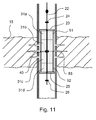
- Fig. 11 shows a further embodiment of the gas generator according to the invention with housing.
- the first limiting element 23 is gas-tightly connected to a first sleeve 51.
- the sleeve 51 encloses a first charge packet, which in the illustrated example comprises two charge units 31 a, 31 b.
- the second limiting element 25 is gas-tightly connected to a second sleeve 52.
- This encloses a second charge packet, which also includes two charge units 31 c, 31 d.
- Sleeves 51, 52 and load units 31 a, 31 b, 31 c, 31 d are dimensioned so that there is only a small distance between the open ends of the sleeves.
- the opposing charge units 31 b and 31 c of the two charge packets may be spaced or touching each other. However, they are not firmly connected.
- connection 53 between the sleeves can be done for example by a spot welding.
- the connection 53 can also be secured by a connecting element which fails due to its material properties or material thickness at a defined pressure, so that the connection is released.
- a thin fastening ring which can be made of a rubber or plastic and non-positively, positively and / or cohesively connected to the sleeves.
- the limiting elements 23, 25 in the starting position are not in contact with their respective fastening elements 24, 26.
- the limiting elements 23, 25 with the sleeves and charge packets attached thereto are movably mounted on the support element 22. This can be achieved for example by clamping on the limiting elements 23, 25, which apply a certain holding force.
- the holding force is chosen to be sufficient to prevent slippage during the introduction of the gas generator into the wellbore, but insufficient to withstand the pressure during the burn-off process.
- the igniter 40 is arranged so that upon ignition both the first and the second charge packet are ignited. After ignition, gas evolution and the resulting increase in pressure destroys joint 53, and the two charge packets in their sleeves move axially along support member 22 toward their respective fasteners 24, 26. These serve as end stops that control the movements of the charge packets stop and limit the distance between the sleeves to a predetermined level.
- the fastening elements 24, 26 are advantageously arranged so that the distance between the open ends of the sleeves is not greater than the perforation region.
- the embodiment according to Fig. 11 can be used advantageously if the charge packets are to be protected from external influences that could damage them, for example, present in the bore aggressive waters or high temperatures in hot holes.
- the gas generator according to the invention can be further improved in that the sleeves are provided in the radial direction inside or outside with an insulation against the heat radiation.
- a further embodiment of a gas generator according to the invention is shown with housing.
- a first sleeve 51 is attached gas-tight.
- the sleeve 51 is provided in its interior with a partition wall 54 which extends in the axial direction from the open end in the direction of the limiting element 23 and separates the sleeve into two chambers.
- right chamber of the first sleeve 51 is closed at the boundary element 23 opposite end by a cover 56.
- a second sleeve 52 is attached gas-tight to the second limiting element 25.
- the sleeve 52 is provided in its interior with a partition wall 55 which extends in the axial direction from the open end in the direction of the limiting element 25 and separates the sleeve into two chambers.
- right chamber of the second sleeve 52 is at the limiting element 25 opposite end closed by a cover 57.
- the half-closed ends of the first sleeve 51 and the second sleeve 52 face each other.
- the chambers of the sleeves are filled with a solid fuel, for example Ballistitpulver.
- a solid fuel for example Ballistitpulver.
- the sleeves are made of a material that is not destroyed when the solid fuel is burned off.
- the chambers closed at the front side with solid fuel charges 33b, 33d are completely filled.
- the chambers open at the end side are completely filled with solid fuel charges 33a, 33c.
- an igniter 40a and 40b are respectively attached to the open side of the chamber.
- the detonators 40a, 40b can be controlled so that the respective solid fuel fillings 33a and 33c are ignited simultaneously or in succession.
- the solid fuel fillings 33a, 33c After ignition, the solid fuel fillings 33a, 33c first burn in the chambers open at the end in the direction of their respective limiting elements 23, 25. As soon as the end of the respective partition wall 54, 55 is reached, the solid fuel fillings 33b, 33d are ignited in the chambers closed at the end and burn off in the direction of the covers 56, 57.
- Fig. 13 schematically illustrates a situation in which the solid fuel charges 33b, 33d are already partially burned in the closed-end chambers.
- FIG. 14 are cross sections through the second sleeve 52 shown in the Fig. 12 and 13 are labeled A - A to D - D.
- the section A - A is axially in the region of the gap between the partition wall 55 and the second limiting element 25 and represents the state before ignition, in which in both chambers of the sleeve still a solid fuel filling 33c, 33d is present.
- Section B - B lies axially in the region of the dividing wall, which in the present example divides the cross section of the sleeve into two equal parts.
- Section C - C corresponds to the section B - B in terms of position, but it shows the situation in which the solid fuel filling 33 c of the frontally open chamber has already burned off.
- Section D - D also shows this situation and corresponds in its axial position to the section A - A.
Landscapes
- Life Sciences & Earth Sciences (AREA)
- Engineering & Computer Science (AREA)
- Geology (AREA)
- Mining & Mineral Resources (AREA)
- Physics & Mathematics (AREA)
- Environmental & Geological Engineering (AREA)
- Fluid Mechanics (AREA)
- General Life Sciences & Earth Sciences (AREA)
- Geochemistry & Mineralogy (AREA)
- Air Bags (AREA)
- Feeding, Discharge, Calcimining, Fusing, And Gas-Generation Devices (AREA)
Priority Applications (1)
| Application Number | Priority Date | Filing Date | Title |
|---|---|---|---|
| EP20110191467 EP2460975A2 (fr) | 2010-12-02 | 2011-12-01 | Dispositif et procédé pour la stimulation du puits. |
Applications Claiming Priority (2)
| Application Number | Priority Date | Filing Date | Title |
|---|---|---|---|
| EP10193464 | 2010-12-02 | ||
| EP20110191467 EP2460975A2 (fr) | 2010-12-02 | 2011-12-01 | Dispositif et procédé pour la stimulation du puits. |
Publications (1)
| Publication Number | Publication Date |
|---|---|
| EP2460975A2 true EP2460975A2 (fr) | 2012-06-06 |
Family
ID=45002846
Family Applications (1)
| Application Number | Title | Priority Date | Filing Date |
|---|---|---|---|
| EP20110191467 Withdrawn EP2460975A2 (fr) | 2010-12-02 | 2011-12-01 | Dispositif et procédé pour la stimulation du puits. |
Country Status (3)
| Country | Link |
|---|---|
| EP (1) | EP2460975A2 (fr) |
| CA (1) | CA2761153A1 (fr) |
| RU (1) | RU2011148955A (fr) |
Cited By (3)
| Publication number | Priority date | Publication date | Assignee | Title |
|---|---|---|---|---|
| WO2014090630A1 (fr) * | 2012-12-13 | 2014-06-19 | Wintershall Holding GmbH | Dispositif et procédé de stimulation d'un forage |
| WO2014090633A1 (fr) * | 2012-12-13 | 2014-06-19 | Wintershall Holding GmbH | Dispositif et procédé de stimulation et de nettoyage d'un trou de forage rempli de liquide |
| WO2015197680A1 (fr) | 2014-06-25 | 2015-12-30 | Wintershall Holding GmbH | Dispositif et procédé pour une stimulation de trou de forage |
Families Citing this family (1)
| Publication number | Priority date | Publication date | Assignee | Title |
|---|---|---|---|---|
| CN111133171A (zh) * | 2017-09-26 | 2020-05-08 | 罗奇弗莱克服务有限公司 | 油井增产装置及其使用方法 |
Citations (5)
| Publication number | Priority date | Publication date | Assignee | Title |
|---|---|---|---|---|
| RU2151282C1 (ru) | 1999-02-08 | 2000-06-20 | Пермский завод им.С.М.Кирова | Устройство для термогазохимической обработки продуктивного пласта |
| RU2176728C1 (ru) | 2000-12-27 | 2001-12-10 | Закрытое Акционерное Общество Пермский Инженерно-Технический Центр "Геофизика" | Способ обработки продуктивного пласта и заряд |
| RU2307921C2 (ru) | 2005-09-26 | 2007-10-10 | Федеральное казенное предприятие "Пермский пороховой завод" (ФКП "Пермский пороховой завод") | Устройство для вскрытия, газодинамической, виброволновой и солянокислой обработки пласта |
| RU2311529C2 (ru) | 2006-01-10 | 2007-11-27 | Федеральное казенное предприятие "Пермский пороховой завод" (ФКП "Пермский пороховой завод") | Газогенератор на твердом топливе для обработки нефтегазовых скважин |
| US20080271894A1 (en) | 2007-05-03 | 2008-11-06 | Baker Hughes Incorporated | Method and apparatus for subterranean fracturing |
-
2011
- 2011-12-01 CA CA 2761153 patent/CA2761153A1/fr not_active Abandoned
- 2011-12-01 RU RU2011148955/03A patent/RU2011148955A/ru not_active Application Discontinuation
- 2011-12-01 EP EP20110191467 patent/EP2460975A2/fr not_active Withdrawn
Patent Citations (5)
| Publication number | Priority date | Publication date | Assignee | Title |
|---|---|---|---|---|
| RU2151282C1 (ru) | 1999-02-08 | 2000-06-20 | Пермский завод им.С.М.Кирова | Устройство для термогазохимической обработки продуктивного пласта |
| RU2176728C1 (ru) | 2000-12-27 | 2001-12-10 | Закрытое Акционерное Общество Пермский Инженерно-Технический Центр "Геофизика" | Способ обработки продуктивного пласта и заряд |
| RU2307921C2 (ru) | 2005-09-26 | 2007-10-10 | Федеральное казенное предприятие "Пермский пороховой завод" (ФКП "Пермский пороховой завод") | Устройство для вскрытия, газодинамической, виброволновой и солянокислой обработки пласта |
| RU2311529C2 (ru) | 2006-01-10 | 2007-11-27 | Федеральное казенное предприятие "Пермский пороховой завод" (ФКП "Пермский пороховой завод") | Газогенератор на твердом топливе для обработки нефтегазовых скважин |
| US20080271894A1 (en) | 2007-05-03 | 2008-11-06 | Baker Hughes Incorporated | Method and apparatus for subterranean fracturing |
Cited By (4)
| Publication number | Priority date | Publication date | Assignee | Title |
|---|---|---|---|---|
| WO2014090630A1 (fr) * | 2012-12-13 | 2014-06-19 | Wintershall Holding GmbH | Dispositif et procédé de stimulation d'un forage |
| WO2014090633A1 (fr) * | 2012-12-13 | 2014-06-19 | Wintershall Holding GmbH | Dispositif et procédé de stimulation et de nettoyage d'un trou de forage rempli de liquide |
| US9856725B2 (en) | 2012-12-13 | 2018-01-02 | Elektro-Thermit Gmbh & Co. Kg | Device and method for well stimulation |
| WO2015197680A1 (fr) | 2014-06-25 | 2015-12-30 | Wintershall Holding GmbH | Dispositif et procédé pour une stimulation de trou de forage |
Also Published As
| Publication number | Publication date |
|---|---|
| CA2761153A1 (fr) | 2012-06-02 |
| RU2011148955A (ru) | 2013-06-10 |
Similar Documents
| Publication | Publication Date | Title |
|---|---|---|
| DE19983440B4 (de) | Vorrichtung und Verfahren zur Erzeugung von seismischer Energie in unterirdischen Formationen | |
| DE69424617T2 (de) | Durch Flüssigkeitsdruck betätigte Vorrichtung zur Durchführung von mehreren Operationen im Bohrloch | |
| EP1202879B1 (fr) | Generateur de gaz du type a cordeau | |
| DE2816248A1 (de) | Vorrichtung zum chemischen schneiden von gegenstaenden in bohrloechern von oel- oder gasfeldern | |
| US9109438B2 (en) | Device and method for well stimulation | |
| DE112014006644B4 (de) | Verfahren zum Steuern von Energie im Inneren einer Perforationskanone unter Verwendung einer endothermen Reaktion | |
| EP2460975A2 (fr) | Dispositif et procédé pour la stimulation du puits. | |
| EP0656522B1 (fr) | Douille pour cartouche | |
| WO2003014522A9 (fr) | Vaporisation in situ | |
| DE602004012126T2 (de) | Verbesserungen bei perforatoren und diese betreffend | |
| DE2360824A1 (de) | Vorrichtung zur verdichtung einer masse innerhalb eines abgegrenzten raumes | |
| DE1949711C3 (de) | Flussiger Sprengstoff und seine An wendung zum Aufbrechen von geologischen Formationen | |
| EP3559590B1 (fr) | Système d'abattage à l'explosif | |
| EP2932026B1 (fr) | Dispositif et procédé de stimulation d'un puits de forage | |
| DE3819297A1 (de) | Fester treibsatz und gasgenerator fuer dessen verwendung | |
| DE2630979A1 (de) | Abbauverfahren | |
| WO2015197680A1 (fr) | Dispositif et procédé pour une stimulation de trou de forage | |
| EP2488720A2 (fr) | Canon de perforation à trous de tir se refermant automatiquement | |
| DE2345663C3 (de) | Verfahren und Vorrichtung zum Aufbrechen von Erdformationen mittels einer Sprengstoffladung | |
| DE102019008516B4 (de) | Schneidladung | |
| EP3407008B1 (fr) | Dispositif de génération d'ondes de choc, en particulier sous forme d'impulsions pneumatiques séquentielles | |
| RU2131512C1 (ru) | Устройство для обработки призабойной зоны пласта нефтяных скважин | |
| DE4218626C1 (en) | Arrangement for reducing cross=sectional area of pipe, e.g. oil conveying pipe - includes explosive charge on 1 of 2 jaws for detonating and forcing jaws against pipe | |
| DE1623546C (de) | Vorrichtung zum Erzeugen von seismischen Wellen mit einem Bodenteil und einem Deckel teil | |
| EP2932025A1 (fr) | Dispositif et procédé de stimulation et de nettoyage d'un trou de forage rempli de liquide |
Legal Events
| Date | Code | Title | Description |
|---|---|---|---|
| PUAI | Public reference made under article 153(3) epc to a published international application that has entered the european phase |
Free format text: ORIGINAL CODE: 0009012 |
|
| AK | Designated contracting states |
Kind code of ref document: A2 Designated state(s): AL AT BE BG CH CY CZ DE DK EE ES FI FR GB GR HR HU IE IS IT LI LT LU LV MC MK MT NL NO PL PT RO RS SE SI SK SM TR |
|
| AX | Request for extension of the european patent |
Extension state: BA ME |
|
| STAA | Information on the status of an ep patent application or granted ep patent |
Free format text: STATUS: THE APPLICATION IS DEEMED TO BE WITHDRAWN |
|
| 18D | Application deemed to be withdrawn |
Effective date: 20170701 |