EP2458309A2 - Storage cartridge for laboratory objects - Google Patents
Storage cartridge for laboratory objects Download PDFInfo
- Publication number
- EP2458309A2 EP2458309A2 EP11009209A EP11009209A EP2458309A2 EP 2458309 A2 EP2458309 A2 EP 2458309A2 EP 11009209 A EP11009209 A EP 11009209A EP 11009209 A EP11009209 A EP 11009209A EP 2458309 A2 EP2458309 A2 EP 2458309A2
- Authority
- EP
- European Patent Office
- Prior art keywords
- storage cassette
- storage
- laboratory
- rear wall
- cassette according
- Prior art date
- Legal status (The legal status is an assumption and is not a legal conclusion. Google has not performed a legal analysis and makes no representation as to the accuracy of the status listed.)
- Granted
Links
- 239000002184 metal Substances 0.000 claims abstract description 17
- 229910052751 metal Inorganic materials 0.000 claims abstract description 17
- 238000005452 bending Methods 0.000 claims description 7
- XEEYBQQBJWHFJM-UHFFFAOYSA-N Iron Chemical compound [Fe] XEEYBQQBJWHFJM-UHFFFAOYSA-N 0.000 claims description 4
- 125000006850 spacer group Chemical group 0.000 claims description 3
- 229910000831 Steel Inorganic materials 0.000 claims description 2
- 229910052742 iron Inorganic materials 0.000 claims description 2
- 239000010959 steel Substances 0.000 claims description 2
- 230000014759 maintenance of location Effects 0.000 claims 1
- 239000000523 sample Substances 0.000 description 19
- 238000001816 cooling Methods 0.000 description 4
- 238000009413 insulation Methods 0.000 description 4
- 238000004519 manufacturing process Methods 0.000 description 2
- 239000000243 solution Substances 0.000 description 2
- 239000012298 atmosphere Substances 0.000 description 1
- 239000011324 bead Substances 0.000 description 1
- 230000015572 biosynthetic process Effects 0.000 description 1
- 230000001419 dependent effect Effects 0.000 description 1
- 230000005484 gravity Effects 0.000 description 1
- 238000003780 insertion Methods 0.000 description 1
- 230000037431 insertion Effects 0.000 description 1
- 239000006101 laboratory sample Substances 0.000 description 1
- 230000007774 longterm Effects 0.000 description 1
- 239000012299 nitrogen atmosphere Substances 0.000 description 1
- 239000000126 substance Substances 0.000 description 1
- 238000004804 winding Methods 0.000 description 1
Images


Classifications
-
- F—MECHANICAL ENGINEERING; LIGHTING; HEATING; WEAPONS; BLASTING
- F25—REFRIGERATION OR COOLING; COMBINED HEATING AND REFRIGERATION SYSTEMS; HEAT PUMP SYSTEMS; MANUFACTURE OR STORAGE OF ICE; LIQUEFACTION SOLIDIFICATION OF GASES
- F25D—REFRIGERATORS; COLD ROOMS; ICE-BOXES; COOLING OR FREEZING APPARATUS NOT OTHERWISE PROVIDED FOR
- F25D25/00—Charging, supporting, and discharging the articles to be cooled
- F25D25/005—Charging, supporting, and discharging the articles to be cooled using containers
-
- F—MECHANICAL ENGINEERING; LIGHTING; HEATING; WEAPONS; BLASTING
- F25—REFRIGERATION OR COOLING; COMBINED HEATING AND REFRIGERATION SYSTEMS; HEAT PUMP SYSTEMS; MANUFACTURE OR STORAGE OF ICE; LIQUEFACTION SOLIDIFICATION OF GASES
- F25D—REFRIGERATORS; COLD ROOMS; ICE-BOXES; COOLING OR FREEZING APPARATUS NOT OTHERWISE PROVIDED FOR
- F25D13/00—Stationary devices, e.g. cold-rooms
- F25D13/02—Stationary devices, e.g. cold-rooms with several cooling compartments, e.g. refrigerated locker systems
- F25D13/04—Stationary devices, e.g. cold-rooms with several cooling compartments, e.g. refrigerated locker systems the compartments being at different temperatures
-
- F—MECHANICAL ENGINEERING; LIGHTING; HEATING; WEAPONS; BLASTING
- F25—REFRIGERATION OR COOLING; COMBINED HEATING AND REFRIGERATION SYSTEMS; HEAT PUMP SYSTEMS; MANUFACTURE OR STORAGE OF ICE; LIQUEFACTION SOLIDIFICATION OF GASES
- F25D—REFRIGERATORS; COLD ROOMS; ICE-BOXES; COOLING OR FREEZING APPARATUS NOT OTHERWISE PROVIDED FOR
- F25D13/00—Stationary devices, e.g. cold-rooms
- F25D13/06—Stationary devices, e.g. cold-rooms with conveyors carrying articles to be cooled through the cooling space
-
- F—MECHANICAL ENGINEERING; LIGHTING; HEATING; WEAPONS; BLASTING
- F25—REFRIGERATION OR COOLING; COMBINED HEATING AND REFRIGERATION SYSTEMS; HEAT PUMP SYSTEMS; MANUFACTURE OR STORAGE OF ICE; LIQUEFACTION SOLIDIFICATION OF GASES
- F25D—REFRIGERATORS; COLD ROOMS; ICE-BOXES; COOLING OR FREEZING APPARATUS NOT OTHERWISE PROVIDED FOR
- F25D3/00—Devices using other cold materials; Devices using cold-storage bodies
- F25D3/10—Devices using other cold materials; Devices using cold-storage bodies using liquefied gases, e.g. liquid air
-
- G—PHYSICS
- G01—MEASURING; TESTING
- G01N—INVESTIGATING OR ANALYSING MATERIALS BY DETERMINING THEIR CHEMICAL OR PHYSICAL PROPERTIES
- G01N35/00—Automatic analysis not limited to methods or materials provided for in any single one of groups G01N1/00 - G01N33/00; Handling materials therefor
- G01N35/0099—Automatic analysis not limited to methods or materials provided for in any single one of groups G01N1/00 - G01N33/00; Handling materials therefor comprising robots or similar manipulators
-
- G—PHYSICS
- G01—MEASURING; TESTING
- G01N—INVESTIGATING OR ANALYSING MATERIALS BY DETERMINING THEIR CHEMICAL OR PHYSICAL PROPERTIES
- G01N35/00—Automatic analysis not limited to methods or materials provided for in any single one of groups G01N1/00 - G01N33/00; Handling materials therefor
- G01N35/02—Automatic analysis not limited to methods or materials provided for in any single one of groups G01N1/00 - G01N33/00; Handling materials therefor using a plurality of sample containers moved by a conveyor system past one or more treatment or analysis stations
- G01N35/028—Automatic analysis not limited to methods or materials provided for in any single one of groups G01N1/00 - G01N33/00; Handling materials therefor using a plurality of sample containers moved by a conveyor system past one or more treatment or analysis stations having reaction cells in the form of microtitration plates
-
- G—PHYSICS
- G01—MEASURING; TESTING
- G01N—INVESTIGATING OR ANALYSING MATERIALS BY DETERMINING THEIR CHEMICAL OR PHYSICAL PROPERTIES
- G01N35/00—Automatic analysis not limited to methods or materials provided for in any single one of groups G01N1/00 - G01N33/00; Handling materials therefor
- G01N2035/00346—Heating or cooling arrangements
- G01N2035/00445—Other cooling arrangements
-
- G—PHYSICS
- G01—MEASURING; TESTING
- G01N—INVESTIGATING OR ANALYSING MATERIALS BY DETERMINING THEIR CHEMICAL OR PHYSICAL PROPERTIES
- G01N35/00—Automatic analysis not limited to methods or materials provided for in any single one of groups G01N1/00 - G01N33/00; Handling materials therefor
- G01N35/02—Automatic analysis not limited to methods or materials provided for in any single one of groups G01N1/00 - G01N33/00; Handling materials therefor using a plurality of sample containers moved by a conveyor system past one or more treatment or analysis stations
- G01N35/04—Details of the conveyor system
- G01N2035/0401—Sample carriers, cuvettes or reaction vessels
- G01N2035/0418—Plate elements with several rows of samples
- G01N2035/0425—Stacks, magazines or elevators for plates
Definitions
- the invention relates to a storage cassette for laboratory objects, in particular for storage at low temperatures. Furthermore, the invention also relates to a storage facility with such a storage cassette and the combination of a storage cassette with at least one laboratory object.
- Storage cassettes for laboratory objects which form a plurality of stacked storage locations for receiving the laboratory objects are, for example WO 02/059251 known. If such storage cassettes are required in large numbers, it must be ensured that they are as simple and inexpensive to produce.
- the object of the present invention is to provide a storage cassette which has a multiplicity of superimposed storage locations for receiving laboratory objects forms to provide, which is inexpensive, robust and easy to produce.
- the storage cassette has a rear wall and two perpendicular to the rear wall side walls.
- the side walls and the rear wall are formed by mutually bent portions of a single piece of sheet metal.
- a ceiling part or bottom part can be arranged at an upper and / or lower end of the bearing cassette, which is advantageously also formed by a bent portion of the same piece of sheet metal. As a result, the robustness of the cassette is further increased and the price lowered.
- the bearings of the storage cassette can be formed by bent angles of the piece of sheet metal on which the laboratory objects can be placed.
- the angle can be formed from the same sheet as the back walls.
- angles on the rear wall advantageously have at its front edge upwardly bent retaining elements in order to keep the laboratory objects slip-proof.
- predetermined bending points are provided in the sheet metal piece in order to facilitate the exact bending of the same.
- These predetermined bending points are preferably formed in the form of elongated holes or slots, which can be mounted in the same step as the cutting of the piece of sheet metal and thus in a well-defined spatial position.
- the invention also relates to a storage facility having at least one chamber and at least one storage cassette arranged in the chamber of the type described above.
- the samples are housed, for example, in sample tubes, which in turn are arranged in plates. In each case several of these sample plates are stored one above the other in a storage cassette.
- the storage facility has an insulated outer housing 2, which encloses a chamber 3.
- a dewar 4 is arranged in the chamber 3 in the chamber 3 in the chamber 3 in the chamber 3 .
- a plurality of such Dewargefässe 4 are provided in the chamber 3 .
- Each dewar 4 has in a known manner an evacuated, mirrored insulation wall, which has low heat conduction.
- the Dewar vessels are closed on all sides in the embodiment shown and to access their interior, a cover 5 is provided in each case.
- the lid covers an opening 6 arranged on the upper side of the Dewar flask.
- the chamber 3 is preferably designed as a cooling chamber.
- Tc of the chamber 3 is advantageously below 0 ° C, especially below -20 ° C or -50 ° C. This lowering of the temperature prevents the formation of ice in the Dewar vessels 4 or on the samples.
- the storage temperature Ts in the Dewar vessels 4 is less than the chamber temperature Tc and is preferably at the mentioned "very low temperatures", i. typically at -196 ° C.
- the chamber 3 may e.g. also contain only a defined atmosphere (for example, dry air or nitrogen atmosphere), or it may be a not particularly air-conditioned storage room.
- a defined atmosphere for example, dry air or nitrogen atmosphere
- a picking device 8 is arranged in the chamber 3.
- This picking device 8 each has a transport device for the storage cassettes, the sample plates and the sample tubes. It is arranged movable above the Dewargefêt 4. How out Fig. 1 and 2 can be seen, it is advantageous exactly a picking device 8 is provided which serves all Dewar vessels.
- the storage facility further comprises a first cooling device 9a for generating the internal temperature Ti in the chamber 3 and a second cooling device 9b for generating the storage temperature Ts in the dewar vessels 4.
- the chamber 3 is accessible via a door 11 which is sufficiently large for receiving the Dewargeftreu 4.
- a positioning drive 22 serves to rotate the carousel 18 about the axis of rotation 16 and to bring it into defined positions.
- the storage cassettes 20 are arranged in several concentric circles about the axis of rotation 16, radially positioned by means of vertical walls 24 and movable in the vertical direction.
- the door 5 can be opened and closed automatically with a door drive 26. It is arranged on the upper side of the Dewar 4 and positioned and dimensioned so that with the door open 5 each storage cassette 20, which was rotated with the positioning drive 22 in the region of the door opening, can be pulled out from above.
- the horizontal diameter of the door opening is smaller than half the horizontal diameter of the Dewar flask 4, so that an excessive loss of cold when opening the door 5 can be avoided.
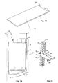
- FIG. 20 A second embodiment of a Dewar flask is in Fig. 20 shown. It is evident in Fig. 20 in particular the double wall with the vacuum insulation 12 and the lid 5 (not shown) closed opening 6.
- a carousel 18 In the interior of the Dewar is again a carousel 18, which carries on its bottom plate 19 a plurality of storage cassettes (not shown).
- the storage cassette forms a plurality of superimposed bearings, each of which can accommodate a sample plate. They are designed to provide high mechanical accuracy over a very wide temperature range. They also have centering and transport devices that allow high mechanical positioning accuracy and automatic transport.
- each bearing point of several angles 40, 42 is formed. These angles form support elements and protrude inward from the side walls 30 (angle 40) and the back wall 32 (angle 42) and form side and rear supports for the sample plates.
- the angle 42 on the rear wall 32 have at its front edge bent, ie bent upwards, retaining elements 44 (see Fig. 7 ), which engage in the inserted sample plate, for example, behind a rear wall thereof, so as to prevent them from slipping forward.
- the side walls 30 of the bearing cassettes 20 are bent over at the front and thus form bent regions 46, with which the storage cassette 20 is positioned laterally in the Dewar 4.
- the bent portions 46 are each laterally on a stationary in the carousel 18 arranged holding element 48 on.
- the bent regions 46 increase the stability of the storage cassettes.
- a vertical bead 47 extends in each side wall.
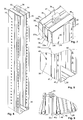
- the side walls 30 and the rear wall 32 are formed by mutually bent portions of a single piece of metal sheet metal.
- the ceiling part 34 and the bottom part 38 are formed by bent portions of the same piece of sheet metal.
- the angle 40, 42 may be formed by bent portions of the sheet metal part. This simplifies the manufacture of the storage cassette and makes the storage cassette robust and temperature-resistant.
- predetermined bending points 39 in particular in the form of elongated holes or slots are provided which simplify a location-accurate bending of the sheet metal piece during manufacture.
- the outline of the piece of sheet metal is cut by laser processing, and also the predetermined bending points 39 are created in the same operation with the laser, so that a high relative position accuracy is ensured.
- the illustrated storage cassette is not only suitable for use in the storage facility described herein but also for use for other purposes, e.g. generally for storage of laboratory objects (such as microtiter plates) inside and outside of climate cabinets.
- Fig. 22 shows a laboratory object in the form of a sample plate 43, which rests on the angles 40, 42. As can be seen, at least two spaced-apart angles 40 are arranged on the side walls.
- Fig. 23 shows the sample plate 43 in a position in which its center of gravity over the front (ie feed side) angle 40 rests.
- the distance A between the angles or supporting elements 40 is selected that tilting of the plate is avoided as possible in this position.
- the distance and lengths of the support elements 40 are selected so that L / 2 - A ⁇ B .
- L is the length of the laboratory plate or the bearing (in the extension direction of the blade)
- A is the distance between the two arranged on the side wall support elements or angles 40 and B, the length of the support elements, in particular the front (ie charging side) support element or Winkels 40, is.
- At least one cassette lift 60 is arranged on the carriage 56, with which bearing cassettes can be removed from the dewar vessels 4 in the vertical direction and inserted again into them.
- two such cassette lifts 60 are provided. They are mounted rotated by 180 ° to each other. This arrangement was chosen because in the execution Fig. 1 and 2
- the Dewar vessels are arranged in two mutually rotated by 180 ° rows, so that per row of Dewar vessels a correspondingly oriented cassette lift 60 is available.
- only one cassette lift 60 could be provided, which can be rotated about a vertical axis by 180 °.
- the Dewar vessels 4 can all be the same orientation, in which case a single, non-rotatable cassette lift is sufficient.
- An envelope device 100 is further provided on the carriage 56. In the execution after Fig. 10 This handling device 100 is arranged between the two cassette lifts 60.
- the structure and function of the handling device 100 essentially correspond to those of the handling device WO 02/059251 ,
- the handling device 100 comprises a vertical guide 102, on which a folding carriage 104 is arranged to be automatically movable in the vertical direction.
- a horizontally extendable blade 106 is provided at the envelope slide 104.
- the blade 106 may preferably be pivoted about at least 180 ° about a vertical axis, so that in the embodiment of Fig. 10 optionally in the storage cassettes 20 of the opposing cassette lifts 60 retract and there record a test plate or can store. Further, it can also be pivoted in the longitudinal direction of the storage facility 1 in order to be arranged at an end in the storage facility 1 transfer station 108 (see Fig. 2 ) place or pick up a sample plate.
- a climate chamber 110 can be provided at the location of the transfer station 108, which is able to exchange laboratory objects or bearing plates with the transfer station 108.
- a first telescoping section 62 is fixedly mounted on the carriage 56.
- a first vertical rail 69 is arranged, on which a first vertical drive 66 is arranged displaceably.
- the vertical drive 66 is connected via a first guide 70 to the first vertical rail 69 and engages with a pinion 72 in a rack 74 on the first telescopic section 62 a.
- a second vertical rail 76 is further arranged, on which the second telescopic section 64 is mounted vertically movable. It is connected via a deflected at the upper end of the first telescopic section 62, flexible, tensile low-temperature-resistant band or a chain 80 to the first vertical drive 66, so that lowering or raising the first vertical drive 66 a booting or lowering the second telescopic section 66 to the same height relative to the first telescopic section 62 causes.
- the second telescopic section 64 can be extended or retracted telescopically.
- a third vertical rail 82 is arranged, on which an arm 84 of the cassette lift 60 is mounted vertically movable.
- the second vertical drive 68 is configured to move the arm 84 vertically relative to the second telescoping section 64.
- the second vertical drive 68 engages with a pinion in a toothed rack 86 on the second telescopic section 64.
- a gripper device 88 is arranged with a gripper drive 89, with which the handle 36 a storage cassette 20 can be taken from above.
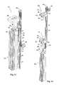
- FIGS. 15-18 show a third embodiment of a cassette lift 60. It corresponds structurally that after Fig. 12 - 14 , with the differences described below.
- the third embodiment of the cassette lift is not based on a telescopic arrangement of elements. Rather, the chain 80 together with rollers 96, 97 a pulley, which serves to lower the gripper device 88 in the Dewar 4. For this purpose, the chain is deflected over at least one lower and at least one upper roller 96 and 97, cf. Fig. 18 , One of the rollers, advantageously the lower roller 96, is displaceable in the vertical direction via the vertical drive 66, while the other roller and the upper end of the chain 80 are vertically stationary.
- the vertical drive is arranged on the first vertical rail 69 of a rail carrier 62 ( Fig. 18 ).
- the rail support 62 corresponds to the first telescopic element 62 of the preceding embodiments and is fixedly arranged on the carriage 56.
- the deflected at the upper end of the cassette lift 60 chain 80 depends vertically downwards and carries at its lower end the gripper device 88 which, as in the second embodiment of the cassette lift, is formed by an electromagnet, with which the respective storage cassette can be magnetically held.
- the gripper device 88 exemplifies the same shape as the handle 36 Fig. 6 However, it forms a separate element from the handle 36.
- the handle 36 may be omitted if the storage cassette 20 can be magnetically held at least at its upper end.
- a steel or iron plate 101 is advantageously provided at an upper end of the storage cassette 20, as in Fig. 20 is shown.
- a guide element 98 is provided which is longitudinally displaceably guided on a second vertical rail 76.
- the second vertical rail 76 is also arranged on the rail carrier 62.
- the guide member 98 forms a lateral guide for the chain 80, preferably an eyelet 116, through which the chain 80 passes.
- the guide member 98 In the lowered position of the storage cassette 20 (see. Fig. 16 ) is the guide member 98 at a stop at the lower end of the second vertical rail 76. If the storage cassette 20 is raised, so the eyelet 116 abuts the gripper 88 and is taken, see. Fig. 16 - 18 ,
- FIGS. 15-18 also has the advantage that it only requires a vertical drive 66, which can also be arranged relatively high up on the lift and does not have to be lowered into the very cold areas of the storage facility.
- the use of a pulley is also advantageous because it allows to reduce the vertical stroke of the engine and so the overall height.
- the chain or band 80 need not necessarily be arranged in a pulley.
- the gripper device 88 for gripping the storage cassettes 20 are lowered on a chain or a band 80 in the Dewar vessels.
- a centering element 95 may also be provided on the dewar 2, as shown in FIGS. 20 and 21 is shown.
- this centering element 95 will be arranged in the opening 6.
- the centering element 95 has an upwardly widening upper collar 96 and a downwardly widening lower collar 97, which simplify insertion of the storage cassette 20 from above or below. It is aligned with lateral feet 98 in the opening 6 in the correct position relative to the carousel 18 and it forms at least one guide opening 99, in which the storage cassette is guided horizontally in the implementation. Between the guide opening 99 and a storage cassette 20, the smallest possible horizontal play of eg maximum 5 mm remains.
- the centering element has a plurality of guide openings 99, which are arranged at different distances from the axis of rotation 16.
- the distances of the guide openings 99 to the axis of rotation 16 correspond to the radii of the circles of the storage shafts in the carousel 18.
- the rear wall 32 of the storage cassettes 20 is constructed so that the holding elements 107 find space to be brought from below behind a held in the storage cassette 20 laboratory object.
- the rear wall 32 as in Fig. 7 shown in two vertically extending side regions 32a set back relative to its central region 32b.
- a first region (middle region 32b) of the rear wall 32 forms a spacer, with respect to which at least one second region (in FIG Fig. 7 the side portions 32a) is recessed, such that the holding members 107 are insertable behind the stored in the storage cassette laboratory objects in the recessed or a corresponding recessed area, ie that the holding elements 107 find space behind the held in the storage cassette laboratory object.
- the storage facility 1 and the storage cassettes 20 serve for the storage of sample tubes.
- samples in other forms, generally suitable for the storage of laboratory objects. These may be, for example, biological or chemical samples.
- a typical application also concerns the storage of laboratory samples in microtiter plates, in which case the sample plates are designed as microtiter plates.
- sample containers eg bottles are used, which each contain only one sample.
Abstract
Description
Die Erfindung betrifft eine Lagerkassette für Laborobjekte, insbesondere für die Lagerung bei tiefen Temperaturen. Weiter betrifft die Erfindung auch eine Lageranlage mit einer derartigen Lagerkassette sowie die Kombination einer Lagerkassette mit mindestens einem Laborobjekt.The invention relates to a storage cassette for laboratory objects, in particular for storage at low temperatures. Furthermore, the invention also relates to a storage facility with such a storage cassette and the combination of a storage cassette with at least one laboratory object.
Lagerkassetten für Laborobjekte, welche eine Vielzahl von übereinander angeordneten Lagerstellen zur Aufnahme der Laborobjekte bilden, sind z.B. aus
Die vorliegende Erfindung stellt sich die Aufgabe, eine Lagerkassette, die eine Vielzahl von übereinander angeordneten Lagerstellen zur Aufnahme von Laborobjekten bildet, bereitzustellen, welche preiswert, robust und einfach herstellbar ist.The object of the present invention is to provide a storage cassette which has a multiplicity of superimposed storage locations for receiving laboratory objects forms to provide, which is inexpensive, robust and easy to produce.
Diese Aufgabe wird von der Lagerkassette gemäss dem zweiten unabhängigen Anspruch erfüllt.This object is achieved by the storage cassette according to the second independent claim.
Demgemäss besitzt die Lagerkassette eine Rückwand und zwei senkrecht zur Rückwand stehende Seitenwände. Dabei werden die Seitenwände und die Rückwand durch zueinander abgebogene Abschnitte eines einzigen Blechstücks gebildet. Eine solche Lagerkassette kann einfach hergestellt werden und ist, aufgrund der kleinen Zahl verwendeter Teile, robust.Accordingly, the storage cassette has a rear wall and two perpendicular to the rear wall side walls. In this case, the side walls and the rear wall are formed by mutually bent portions of a single piece of sheet metal. Such a storage cassette can be easily manufactured and, due to the small number of parts used, robust.
Weiter kann an einem oberen und/oder unteren Ende der Lagerkassette ein Deckenteil bzw. Bodenteil angeordnet sein, der vorteilhaft ebenfalls von einem abgebogenen Abschnitt desselben Blechstücks gebildet wird. Hierdurch wird die Robustheit der Kassette weiter erhöht und der Preis gesenkt.Further, a ceiling part or bottom part can be arranged at an upper and / or lower end of the bearing cassette, which is advantageously also formed by a bent portion of the same piece of sheet metal. As a result, the robustness of the cassette is further increased and the price lowered.
Die Lagerstellen der Lagerkassette können von abgebogenen Winkeln des Blechstücks gebildet werden, auf welche die Laborobjekte aufgesetzt werden können. Somit können also auch die Winkel aus demselben Blech geformt werden wie die Rückwände.The bearings of the storage cassette can be formed by bent angles of the piece of sheet metal on which the laboratory objects can be placed. Thus, therefore, the angle can be formed from the same sheet as the back walls.
Die Winkel an der Rückwand weisen vorteilhaft an ihrer Vorderkante nach oben gebogene Rückhalteelemente auf, um die Laborobjekte rutschsicher zu halten.The angles on the rear wall advantageously have at its front edge upwardly bent retaining elements in order to keep the laboratory objects slip-proof.
Vorteilhaft sind im Blechstück Sollbiegestellen vorgesehen, um das ortsgenaue Biegen desselben zu erleichtern. Diese Sollbiegestellen werden vorzugsweise in Form von länglichen Löchern oder Schlitzen gebildet, welche im selben Arbeitsschritt wie das Zuschneiden des Blechstücks und somit in gut definierter räumlicher Lage angebracht werden können.Advantageously, predetermined bending points are provided in the sheet metal piece in order to facilitate the exact bending of the same. These predetermined bending points are preferably formed in the form of elongated holes or slots, which can be mounted in the same step as the cutting of the piece of sheet metal and thus in a well-defined spatial position.
Die Erfindung betrifft auch eine Lageranlage mit mindestens einer Kammer und mindestens einer in der Kammer angeordneten Lagerkassette der oben beschriebenen Art.The invention also relates to a storage facility having at least one chamber and at least one storage cassette arranged in the chamber of the type described above.
Weitere Ausgestaltungen, Vorteile und Anwendungen der Erfindung ergeben sich aus den abhängigen Ansprüchen und aus der nun folgenden Beschreibung anhand der Figuren. Dabei zeigen:
-
Fig. 1 eine Ansicht einer Lageranlage, wobei die Aussenwände nur teilweise dargestellt sind, -
Fig. 2 eine zweite Ansicht der Lageranlage vonFig. 1 , -
Fig. 3 eine Ansicht eines Dewargefässes, -
Fig. 4 das Dewargefäss vonFig. 3 von oben, mit teilweise entfernter Wand, -
Fig. 5 das Dewargefäss vonFig. 4 von der Seite, -
Fig. 6 eine Lagerkassette, -
Fig. 7 das obere Ende der Lagerkassette vonFig. 6 , -
Fig. 8 das unteren Ende der Lagerkassette vonFig. 6 , -
Fig. 9 die Anordnung von Lagerkassetten in einem Dewargefäss, -
Fig. 10 eine Kommissioniervorrichtung -
Fig. 11 eine erste Ausführung eines Kassettenlifts, -
Fig. 12 eine zweite Ausführung eines Kassettenlifts in heruntergefahrener Stellung, -
Fig. 13 den Kassettenlift vonFig. 12 in mittlerer Stellung, -
Fig. 14 den Kassettenlift vonFig. 12 in hochgefahrener Stellung, -
Fig. 15 eine dritte Ausführung eines Kassettenlifts in heruntergefahrener Stellung, -
Fig. 16 den Kassettenlift vonFig. 15 in mittlerer Stellung, -
Fig. 17 den Kassettenlift vonFig. 15 in hochgefahrener Stellung, -
Fig. 18 eine Seitenansicht des Kassettenlifts vonFig. 17 , -
Fig. 19 die Schaufel ausFig. 10 im Detail, -
Fig. 20 einen Teilschnitt durch eine zweite Ausführung eines Dewargefässes, -
Fig. 21 eine Lagerkassette mit einer zweiten Ausführung des Zentrierelements, -
Fig. 22 eine Seitenansicht eines vollständig eingesetzten Laborobjekts und -
Fig. 23 eine Seitenansicht eines teilweise eingesetzten Laborobjekts.
-
Fig. 1 a view of a storage facility, wherein the outer walls are only partially shown, -
Fig. 2 a second view of the warehouse ofFig. 1 . -
Fig. 3 a view of a Dewar flask, -
Fig. 4 the dewar ofFig. 3 from above, with partially removed wall, -
Fig. 5 the dewar ofFig. 4 of the page, -
Fig. 6 a storage cassette, -
Fig. 7 the upper end of the storage cassette fromFig. 6 . -
Fig. 8 the lower end of the storage cassette ofFig. 6 . -
Fig. 9 the arrangement of storage cassettes in a Dewar flask, -
Fig. 10 a picking device -
Fig. 11 a first embodiment of a cassette lift, -
Fig. 12 a second embodiment of a cassette lift in the lowered position, -
Fig. 13 the cassette lift ofFig. 12 in middle position, -
Fig. 14 the cassette lift ofFig. 12 in the raised position, -
Fig. 15 a third embodiment of a cassette lift in the shut down position, -
Fig. 16 the cassette lift ofFig. 15 in middle position, -
Fig. 17 the cassette lift ofFig. 15 in the raised position, -
Fig. 18 a side view of the cassette lift ofFig. 17 . -
Fig. 19 the shovel outFig. 10 in detail, -
Fig. 20 a partial section through a second embodiment of a Dewar flask, -
Fig. 21 a storage cassette with a second embodiment of the centering element, -
Fig. 22 a side view of a fully used laboratory object and -
Fig. 23 a side view of a partially used laboratory object.
Lageranlage:
-
Fig. 1 und2 zeigen eine Lageranlage 1 zur Langzeitlagerung von Proben bei sehr tiefen Temperaturen, insbesondere einer Lagertemperatur Ts unterhalb 160°C, typischerweise bei -196°C. Die Lageranlage ist dazu ausgestaltet, die Proben automatisch ein- und auszulagern und innerhalb der Lageranlage zwischen unterschiedlichen Lagerpositionen zu bewegen. Anlagen dieser Art haben hohe Anforderungen betreffend Sicherheit für die Proben, Zuverlässigkeit und Energieeffizienz zu erfüllen.
-
Fig. 1 and2 show a storage facility 1 for long-term storage of samples at very low temperatures, in particular a storage temperature Ts below 160 ° C, typically at -196 ° C. The storage facility is designed to automatically load and unload the samples and to move them between different storage positions within the storage facility. Systems of this type have to meet high requirements regarding safety for the samples, reliability and energy efficiency.
Die Proben sind beispielsweise in Probenröhrchen untergebracht, welche ihrerseits in Platten angeordnet sind. Jeweils mehrere dieser Probenplatten werden übereinander in einer Lagerkassette gelagert.The samples are housed, for example, in sample tubes, which in turn are arranged in plates. In each case several of these sample plates are stored one above the other in a storage cassette.
Die Lageranlage besitzt ein isoliertes Aussengehäuse 2, das eine Kammer 3 umschliesst. In der Kammer 3 ist mindestens ein Dewargefäss 4 angeordnet. Vorzugsweise sind mehrere solche Dewargefässe 4 vorgesehen. Jedes Dewargefäss 4 weist in bekannter Weise eine evakuierte, verspiegelte Isolationswand auf, welche geringe Wärmeleitung besitzt. Die Dewargefässe sind in der gezeigten Ausführung allseitig geschlossen und zum Zugriff auf ihren Innenraum ist jeweils ein Deckel 5 vorgesehen. Der Deckel bedeckt eine auf der Oberseite des Dewargefässes angeordnete Öffnung 6.The storage facility has an insulated
Die Kammer 3 ist vorzugsweise als Kühlkammer ausgestaltet. Tc der Kammer 3 liegt vorteilhaft unter 0°C, insbesondere unter -20°C oder -50°C. Dieses Absenken der Temperatur verhindert die Eisbildung in den Dewargefässen 4 bzw. an den Proben. Die Lagertemperatur Ts in den Dewargefässen 4 ist kleiner als die Kammertemperatur Tc und liegt vorzugsweise bei den erwähnten "sehr tiefen Temperaturen", d.h. typisch bei -196 °C.The
Eine Kühlung der Kammer 3 ist allerdings nicht absolut notwendig. Die Kammer 3 kann z.B. auch lediglich eine definierte Atmosphäre (beispielsweise trockene Luft oder Stickstoffatmosphäre) enthalten, oder es kann sich um einen nicht besonders klimatisierten Lagerraum handeln.However, a cooling of the
Weiter ist in der Kammer 3 eine Kommissioniervorrichtung 8 angeordnet. Diese Kommissioniervorrichtung 8 verfügt über je eine Transportvorrichtung für die Lagerkassetten, die Probenplatten und die Probenröhrchen. Sie ist verfahrbar oberhalb der Dewargefässe 4 angeordnet. Wie aus
Die Lageranlage umfasst weiter eine erste Kühlvorrichtung 9a zum Erzeugen der Innentemperatur Ti in der Kammer 3 sowie eine zweite Kühlvorrichtung 9b zum Erzeugen der Lagertemperatur Ts in den Dewargefässen 4.The storage facility further comprises a
Die Kammer 3 ist über eine Türe 11 zugänglich, welche ausreichend gross für die Aufnahme der Dewargefässe 4 ist.The
Dewargefässe:
- Eine erste Ausführung eines Dewargefässes 4 ist in
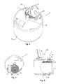
Fig. 3 - 5 dargestellt. Es besitzt ein im Wesentlichen zylindrisches Gehäuse 10, in welchem die oben erwähnte Vakuumisolation 12 angebracht ist.Die Vakuumisolation 12 umschliesst einen Innenraum 14, der ein um eine vertikale Drehachse 16 drehbares Karussell 18 aufnimmt.Das Karussell 18 trägt auf einer Bodenplatte 19 eineVielzahl von Lagerkassetten 20.
- A first embodiment of a
Dewar flask 4 is inFig. 3-5 shown. It has a substantiallycylindrical housing 10, in which the above-mentionedVacuum insulation 12 is attached. Thevacuum insulation 12 encloses aninterior space 14 which receives acarousel 18 rotatable about a vertical axis ofrotation 16. Thecarousel 18 carries on a bottom plate 19 a plurality of storage cassettes 20th
Ein Positionierantrieb 22 dient dazu, das Karussell 18 um die Drehachse 16 zu drehen und in definierte Positionen zu bringen.A
Die Lagerkassetten 20 sind in mehreren konzentrischen Kreisen um die Drehachse 16 angeordnet, mittels vertikalen Wänden 24 radial positioniert und in vertikaler Richtung beweglich.The storage cassettes 20 are arranged in several concentric circles about the axis of
Die Türe 5 kann mit einem Türantrieb 26 automatisch geöffnet und geschlossen werden. Sie ist an der Oberseite des Dewargefässes 4 angeordnet und so positioniert und dimensioniert, dass bei geöffneter Türe 5 jede Lagerkassette 20, die mit dem Positionierantrieb 22 in den Bereich der Türöffnung gedreht wurde, von oben herausgezogen werden kann. Vorzugsweise ist der horizontale Durchmesser der Türöffnung jedoch kleiner als der halbe horizontale Durchmesser des Dewargefässes 4, so dass ein übermässiger Kälteverlust beim Öffnen der Türe 5 vermieden werden kann.The
Eine zweite Ausführung eines Dewargefässes ist in
In der Ausführung nach
Lagerkassetten:
- In
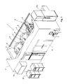
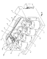
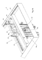
Fig. 6 - 8 ist eine vorteilhafte Lagerkassette 20 dargestellt. Sie verfügt über zwei parallele, vertikale Seitenwände 30 und senkrecht dazu über eine vertikale Rückwand 32.Gegenüber der Rückwand 32 ist dieLagerkassette 20 offen, so dass auf die inder Lagerkassette 20 untergebrachten Probeplatten zugegriffen werden kann. Am oberen Ende derLagerkassette 20ist ein Deckenteil 34 angeordnet, an welchem dieSeitenwände 30 und dieRückwand 32 sowie ein nach oben ragender Haltegriff 36 befestigt sind.Der Haltegriff 36 dient der weiter unten beschriebenen Kommissioniervorrichtung zum Ergreifen der Kassette. Am unteren Ende derLagerkassette 20ist ein Bodenteil 38 angeordnet, an welchem wiederum dieSeitenwände 30 und dieRückwand 32 befestigt sind.
- In
Fig. 6-8 anadvantageous storage cassette 20 is shown. It has two parallel,vertical side walls 30 and perpendicular thereto via a verticalrear wall 32. Opposite therear wall 32, thestorage cassette 20 is open, so that the accommodated in thestorage cassette 20 sample plates can be accessed. At the upper end of thestorage cassette 20, aceiling part 34 is arranged, on which theside walls 30 and therear wall 32 and an upwardly projectinghandle 36 are attached. Thehandle 36 serves the picking device described below for gripping the cassette. At the lower end of thestorage cassette 20, abottom part 38 is arranged, on which in turn theside walls 30 and therear wall 32 are attached.
Die Lagerkassette bildet eine Vielzahl von übereinander angeordneten Lagerstellen, von denen jede eine Probeplatte aufnehmen kann. Sie sind so aufgebaut, dass sie eine hohe mechanische Genauigkeit über einen sehr weiten Temperaturbereich gewährleisten. Ferner verfügen sie über Zentrier- und Transportvorrichtungen, die eine hohe mechanische Positioniergenauigkeit bzw. den automatischen Transport ermöglichen.The storage cassette forms a plurality of superimposed bearings, each of which can accommodate a sample plate. They are designed to provide high mechanical accuracy over a very wide temperature range. They also have centering and transport devices that allow high mechanical positioning accuracy and automatic transport.
Im dargestellten Ausführungsbeispiel wird jede Lagerstelle von mehreren Winkeln 40, 42 gebildet. Diese Winkel bilden Auflageelemente und stehen von den Seitenwänden 30 (Winkel 40) bzw. der Rückwand 32 (Winkel 42) nach innen ab und bilden seitliche und rückseitige Auflagen für die Probenplatten. Die Winkel 42 an der Rückwand 32 weisen an deren Vorderkante aufgebogene, d.h. nach oben gebogene, Rückhalteelemente 44 auf (siehe
Die Seitenwände 30 der Lagerkassetten 20 sind an der Vorderseite umgebogen und bilden so umgebogene Bereiche 46, mit welchen die Lagerkassette 20 im Dewargefäss 4 seitlich positioniert wird. Wie in
Wie insbesondere aus
Zwischen mindestens einem Teil der abgebogenen Abschnitte des Blechstücks sind Sollbiegestellen 39, insbesondere in Form von länglichen Löchern oder Schlitzen vorgesehen, welche ein ortsgenaues Biegen des Blechstücks bei der Herstellung vereinfachen.Between at least a portion of the bent portions of the sheet metal piece predetermined bending points 39, in particular in the form of elongated holes or slots are provided which simplify a location-accurate bending of the sheet metal piece during manufacture.
Vorteilhaft wird der Umriss des Blechstücks mittels Laserbearbeitung zugeschnitten, und auch die Sollbiegestellen 39 werden im gleichen Arbeitsgang mit dem Laser erstellt, so dass eine hohe relative Positionsgenauigkeit gewährleistet ist.Advantageously, the outline of the piece of sheet metal is cut by laser processing, and also the predetermined bending points 39 are created in the same operation with the laser, so that a high relative position accuracy is ensured.
Die dargestellte Lagerkassette eignet sich nicht nur zur Anwendung in der hier beschriebenen Lageranlage, sondern auch zur Verwendung zu anderen Zwecken, z.B. generell zur Lagerung von Laborobjekten (wie z.B. Mikrotiterplatten) innerhalb und ausserhalb von Klimaschränken.The illustrated storage cassette is not only suitable for use in the storage facility described herein but also for use for other purposes, e.g. generally for storage of laboratory objects (such as microtiter plates) inside and outside of climate cabinets.
![]()
![]()
Kommissioniervorrichtung:
Die Kommissioniervorrichtung 8 ist inFig. 10 genauer dargestellt. Sie besitzt einenWagen 50, der horizontal entlang einer ortsfest in der Lageranlage 1 angeordneten ersten Schiene 52 verfahren werden kann, wozuein erster Horizontalantrieb 54 vorgesehen ist.Im Wagen 50ist ein Schlitten 56 angeordnet, der horizontal entlang einer zweiten Schiene 58, welche senkrecht zur erstenSchiene am Wagen 50 angeordnet ist, verfahren werden kann. Hierzu istein zweiter Horizontalantrieb 59 vorgesehen. Auf diese Weise ist der Schlitten 56 horizontal in allen Richtungen verfahrbar.
- The
picking device 8 is inFig. 10 shown in more detail. It has acarriage 50, which can be moved horizontally along a stationary in the bearing system 1 arrangedfirst rail 52, to which a firsthorizontal drive 54 is provided. In thecarriage 50, acarriage 56 is arranged, which can be moved horizontally along a second rail 58, which is arranged perpendicular to the first rail on thecarriage 50. For this purpose, a secondhorizontal drive 59 is provided. In this way, thecarriage 56 is horizontally movable in all directions.
Am Schlitten 56 ist mindestens ein Kassettenlift 60 angeordnet, mit welchem Lagerkassetten in vertikaler Richtung aus den Dewargefässen 4 entnommen und wieder in diese eingesetzt werden können.At least one
In der Ausführung nach
Der Aufbau des Kassettenlifts wird weiter unten beschrieben.The structure of the cassette lift will be described later.
Am Schlitten 56 ist weiter eine Umschlagvorrichtung 100 vorgesehen. In der Ausführung nach
Der Aufbau und die Funktion der Umschlagvorrichtung 100 entsprechen im Wesentlichen jenen der Umschlagvorrichtung gemäss
Die Umschlagvorrichtung 100 umfasst eine Vertikalführung 102, an welcher in Vertikalrichtung automatisch verfahrbar ein Umschlagschlitten 104 angeordnet ist. Am Umschlagschlitten 104 ist eine horizontal ausfahrbare Schaufel 106 vorgesehen. Die Schaufel 106 kann vorzugsweise um mindestens 180° um eine vertikale Achse verschwenkt werden, so dass sie in der Ausführung nach
Ausserhalb des Aussengehäuses kann am Ort der Übergabestation 108 ein Klimaschrank 110 vorgesehen sein, welcher in der Lage ist, Laborobjekte oder Lagerplatten mit der Übergabestation 108 auszutauschen.Outside the outer housing, a
Kassettenlift:
-
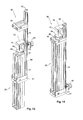
Fig. 11 zeigt eine ersten Ausführung eines Kassettenlifts. In dieser Ausführung besitzt jeder Kassettenlift 60 mehrere teleskopartig zueinander ausfahrbare Teleskopabschnitte 62, 64 sowie eine entsprechendeAnzahl von Vertikalantrieben
-
Fig. 11 shows a first embodiment of a cassette lift. In this embodiment, eachcassette lift 60 has a plurality of telescopically extendabletelescopic sections vertical drives 66, 68th
Ein erster Teleskopabschnitt 62 ist stationär am Schlitten 56 befestigt. Am ersten Teleskopabschnitt 62 ist eine erste Vertikalschiene 69 angeordnet, auf der ein erster Vertikalantrieb 66 verschiebbar angeordnet ist. Der Vertikalantrieb 66 ist über eine erste Führung 70 mit der ersten Vertikalschiene 69 verbunden und greift mit einem Ritzel 72 in eine Zahnstange 74 am ersten Teleskopabschnitt 62 ein.A
Am ersten Teleskopabschnitt 62 ist weiter eine zweite Vertikalschiene 76 angeordnet, an welcher der zweite Teleskopabschnitt 64 vertikal verfahrbar befestigt ist. Er ist über ein am oberen Ende des ersten Teleskopabschnitts 62 umgelenktes, flexibles, zugfestes tieftemperaturfestes Band oder eine Kette 80 mit dem ersten Vertikalantrieb 66 verbunden, so dass ein Absenken bzw. Hochfahren des ersten Vertikalantriebs 66 ein Hochfahren bzw. Absenken des zweiten Teleskopabschnitts 66 um dieselbe Höhe relativ zum ersten Teleskopabschnitt 62 bewirkt. Somit kann mit dem ersten Vertikalantrieb 64 der zweite Teleskopabschnitt 64 teleskopartig ausgefahren bzw. eingefahren werden.On the first
Am zweiten Teleskopabschnitt 64 ist eine dritte Vertikalschiene 82 angeordnet, an welcher ein Arm 84 des Kassettenlifts 60 vertikal verfahrbar gelagert ist. Der zweite Vertikalantrieb 68 ist dazu ausgestaltet, den Arm 84 vertikal gegenüber dem zweiten Teleskopabschnitt 64 zu bewegen. In der in
Am Arm 84 ist eine Greifervorrichtung 88 mit einem Greiferantrieb 89 angeordnet, mit welchem der Haltegriff 36 einer Lagerkassette 20 von oben ergriffen werden kann.On the
Auf fester Höhe am Schlitten 56 oder am ersten Teleskopabschnitt 62 oberhalb der Greifervorrichtung 88 ist mindestens ein Zentrierelement 90 vorgesehen, welches einen sich nach oben verjüngenden Sitz zur Aufnahme einer Lagerkassette 20 bildet, wenn die Lagerkassette mit dem Kassettenlift 60 bis in ihre oberste Stellung gefahren wird. Da gleichzeitig die Greifervorrichtung 88 seitlich etwas Spiel besitzt, definiert das Zentrierelement 90 die horizontale Position der angehobenen Lagerkassette 20 und ermöglicht es somit, die Lagerkassette horizontal exakt auszurichten.At a fixed height on the
Der zweite Vertikalantrieb 68 ist nicht amArm 84 angeordnet, sondern amoberen Ende 92 des zweiten Teleskopabschnitts 64. Er bildet eine Winde für eine Kette 94, an deren unteren Ende derArm 84 befestigt ist. So kann derArm 84 durch Auf- bzw.Abwickeln der Kette 94 hoch- bzw. heruntergefahren werden. Diese Lösung hat den Vorteil, dass der zweite Vertikalantrieb festam zweiten Teleskopabschnitt 64 befestigt werden kann und nicht so weit nach unten in den Tieftemperaturbereich abgesenkt werden muss.- Es sind zwei vertikal voneinander beabstandete Zentrierelemente 90, 91 vorgesehen.
Ein oberes Zentrierelement 90 ist ungefähr gleichwie das Zentrierelement 90 der ersten Ausführung aufgebaut und bildet wieder einen sich nach oben verjüngenden Sitz für dieLagerkassette 20, währenddas untere Zentrierelement 91 einen sich nach oben verjüngenden Kragen bildet, in den dieLagerkassette 20 beim Hochfahren einfährt. Bei der hochgefahrenen Lagerkassette 20 kommtdas obere Zentrierelement 90 im Bereich des oberen Endes der Lagerkassette 20 unddas untere Zentrierelement 91 im Bereich des unteren Endes der Lagerkassette 20 zu liegen, so dass diehochgefahrene Lagerkassette 20 an beiden Enden horizontal geführt ist. Um eine Führung mit geringer Reibung zu gewährleisten, sind an denZentrierelementen gefederte Rollenlager 93 vorgesehen (Fig. 12 ). Die Greifvorrichtung 88 ist als Elektromagnet ausgeführt.
- The second
vertical drive 68 is not disposed on thearm 84, but at theupper end 92 of the secondtelescopic section 64. It forms a winch for achain 94, at the lower end of thearm 84 is attached. Thus, thearm 84 can be moved up or down by winding or unwinding thechain 94. This solution has the advantage that the second vertical drive can be firmly fixed to the secondtelescopic section 64 and does not have to be lowered so far down into the low-temperature range. - There are two vertically spaced centering 90, 91 are provided. An upper centering
element 90 is constructed approximately the same as the centeringelement 90 of the first embodiment and again forms an upwardly tapering seat for thestorage cassette 20, while the lower centering 91 forms an upwardly tapering collar into which thestorage cassette 20 retracts during startup , In the raisedstorage cassette 20, the upper centeringelement 90 comes in the region of the upper end of thestorage cassette 20 and the lower centering 91 in the region of the lower End of thestorage cassette 20 to lie, so that the raisedstorage cassette 20 is guided horizontally at both ends. In order to ensure a guide with low friction, sprungroller bearings 93 are provided on the centering elements (Fig. 12 ). - The
gripping device 88 is designed as an electromagnet.
Die dritte Ausführung des Kassettenlifts basiert nicht auf einer teleskopartigen Anordnung von Elementen. Vielmehr bildet die Kette 80 zusammen mit Rollen 96, 97 einen Flaschenzug, der dazu dient, die Greifervorrichtung 88 in die Dewargefässe 4 abzusenken. Hierzu ist die Kette über mindestens eine untere und mindestens eine obere Rolle 96 bzw. 97 umgelenkt, vgl.
In der dargestellten Ausführung ist der Vertikalantrieb an der ersten Vertikalschiene 69 eines Schienenträgers 62 angeordnet (
Die am oberen Ende des Kassettenlifts 60 umgelenkte Kette 80 hängt vertikal nach unten und trägt an ihrem unteren Ende die Greifervorrichtung 88, welche, wie in der zweiten Ausführung des Kassettenlifts, von einem Elektromagneten gebildet wird, mit welchem die jeweilige Lagerkassette magnetisch festgehalten werden kann. (In
Um das Ergreifen einer Lagerkassette 20 mittels Magnetkraft zu erleichtern, ist vorteilhaft an einem oberen Ende der Lagerkassette 20 eine Stahl- oder Eisenplatte 101 vorgesehen, wie sie in
Um die Kette 80 seitlich etwas zu stabilisieren, ist ein Führungselement 98 vorgesehen, welches längsverschiebbar an einer zweiten Vertikalschiene 76 geführt ist. Die zweite Vertikalschiene 76 ist ebenfalls am Schienenträger 62 angeordnet. Das Führungselement 98 bildet eine seitliche Führung für die Kette 80, vorzugsweise eine Öse 116, durch welche die Kette 80 läuft. In der abgesenkten Stellung der Lagerkassette 20 (vgl.
Die Ausführung nach
Die Verwendung eines Flaschenzugs ist zudem vorteilhaft, weil sie es erlaubt, den Vertikalhub des Motors und so die Bauhöhe zu reduzieren. Die Kette oder das Band 80 braucht jedoch nicht unbedingt in einem Flaschenzug angeordnet zu sein. Anstelle eines Flaschenzugs ist es z.B. auch möglich, das Band oder die Kette 80 auf eine angetriebene Rolle bzw. Winde aufzurollen bzw. von dieser abzurollen, wie in der in
Zentrierelement im DewargefässCentering element in the Dewar flask
Zusätzlich oder alternativ zu den Zentrierelementen 90 und 91 kann auch ein Zentrierelement 95 am Dewargefäss 2 vorgesehen sein, wie es in
In der Ausführung nach
Bemerkungen:
- An der Schaufel 106 (vgl.
Fig. 10 ) ist vorzugsweise und wie inFig. 19 gezeigt mindestens ein nach oben gerichtetes, insbesondere schräg nach oben gerichtetes,Halteelement 107, z.B. in der Form eines Fingers, angeordnet, und zwar an jenem Ende derSchaufel 106, mit welchem voran sie indie Lagerkassetten 20 eingefahren wird. In der Ausführung nachFig. 19 sind zwei derartige Haltelemente 107 beabstandet voneinander angeordnet. DieseHaltelemente 107 dienen dazu, die Laborobjekte auf der Schaufel von hinten zu sichern, so dass sie nicht von der Schaufel fallen. Mit anderen Worten besitzt die Schaufel alsomindestens ein Haltelement 107, mit welchem ein aufzunehmendes Laborobjekt hintergriffen werden kann.
- On the blade 106 (see.
Fig. 10 ) is preferably and as inFig. 19 shown at least one upwardly directed, in particular obliquely upwardly directed, holdingelement 107, for example in the form of a finger, arranged, namely at that end of theblade 106, with which it is moved into thestorage cassettes 20 first. In the execution afterFig. 19 are twosuch Holding elements 107 spaced from each other. These holdingelements 107 serve to secure the laboratory objects on the blade from behind, so that they do not fall off the blade. In other words, the blade thus has at least one retainingelement 107, with which a male laboratory object can be engaged.
Die Rückwand 32 der Lagerkassetten 20 ist so aufgebaut, dass die Halteelemente 107 Platz finden, um von unten her hinter ein in der Lagerkassette 20 gehaltenen Laborobjekt gebracht zu werden. Hierzu ist die Rückwand 32, wie in
In der obigen Beschreibung wird erwähnt, dass die Lageranlage 1 sowie die Lagerkassetten 20 zur Lagerung von Probenröhrchen dienen. Sie sind jedoch auch zur Lagerung von Proben in anderer Form geeignet, generell zur Lagerung von Laborobjekten, geeignet. Dabei kann es sich z.B. um biologische oder chemische Proben handeln. Eine typische Anwendung betrifft auch die Lagerung von Laborproben in Mikrotiterplatten, in welchem Fall die Probenplatten als Mikrotiterplatten ausgestaltet sind. Denkbar ist es auch, dass anstelle der Probenplatten Probenbehälter, z.B. Flaschen verwendet werden, welche jeweils nur eine Probe enthalten.In the above description, it is mentioned that the storage facility 1 and the
Während in der vorliegenden Anmeldung bevorzugte Ausführungen der Erfindung beschrieben sind, ist klar darauf hinzuweisen, dass die Erfindung nicht auf diese beschränkt ist und in auch anderer Weise innerhalb des Umfangs der folgenden Ansprüche ausgeführt werden kann.While preferred embodiments of the invention are described in the present application, it is to be understood that the invention is not limited thereto and may be embodied otherwise within the scope of the following claims.
Claims (12)
wobei die Seitenwände (30) und die Rückwand (32) durch zueinander abgebogene Abschnitte eines einzigen Blechstücks gebildet werden.
wherein the side walls (30) and the rear wall (32) are formed by mutually bent portions of a single piece of sheet metal.

erfüllt ist, wobei L eine Länge der der Lagerstelle, A ein Abstand der mindestens zwei Auflageelemente und B eine Länge eines der Auflageelemente ist.Storage cassette according to one of the preceding claims, wherein on each side wall per bearing point at least two support elements, in particular angle (40), are provided
is satisfied, wherein L is a length of the bearing, A is a distance of at least two support elements and B is a length of the support elements.
erfüllt ist, wobei L eine Länge der des Laborobjekts, A ein Abstand der mindestens zwei Auflageelemente und B eine Länge eines der Auflageelemente ist.Combination of a storage cassette according to one of the preceding claims and at least one laboratory object, wherein on each side wall per bearing point at least two support elements, in particular angle (40), are provided
is satisfied, where L is a length of the laboratory object, A is a distance of at least two support elements and B is a length of one of the support elements.
Applications Claiming Priority (1)
| Application Number | Priority Date | Filing Date | Title |
|---|---|---|---|
| CH01968/10A CH704128A1 (en) | 2010-11-24 | 2010-11-24 | Storage facility for low temperatures and bearing cartridge for laboratory objects. |
Publications (3)
| Publication Number | Publication Date |
|---|---|
| EP2458309A2 true EP2458309A2 (en) | 2012-05-30 |
| EP2458309A3 EP2458309A3 (en) | 2015-07-15 |
| EP2458309B1 EP2458309B1 (en) | 2019-08-07 |
Family
ID=45098787
Family Applications (4)
| Application Number | Title | Priority Date | Filing Date |
|---|---|---|---|
| EP20215024.9A Active EP3812674B1 (en) | 2010-11-24 | 2011-11-21 | Storage system for storing laboratory objects at low temperatures |
| EP11009209.5A Active EP2458309B1 (en) | 2010-11-24 | 2011-11-21 | Storage cartridge for laboratory objects |
| EP11009208.7A Active EP2458308B1 (en) | 2010-11-24 | 2011-11-21 | Storage system for storing laboratory objects in low temperatures |
| EP19185530.3A Active EP3581864B1 (en) | 2010-11-24 | 2011-11-21 | Storage system for storing laboratory objects in low temperatures |
Family Applications Before (1)
| Application Number | Title | Priority Date | Filing Date |
|---|---|---|---|
| EP20215024.9A Active EP3812674B1 (en) | 2010-11-24 | 2011-11-21 | Storage system for storing laboratory objects at low temperatures |
Family Applications After (2)
| Application Number | Title | Priority Date | Filing Date |
|---|---|---|---|
| EP11009208.7A Active EP2458308B1 (en) | 2010-11-24 | 2011-11-21 | Storage system for storing laboratory objects in low temperatures |
| EP19185530.3A Active EP3581864B1 (en) | 2010-11-24 | 2011-11-21 | Storage system for storing laboratory objects in low temperatures |
Country Status (3)
| Country | Link |
|---|---|
| US (2) | US9005542B2 (en) |
| EP (4) | EP3812674B1 (en) |
| CH (1) | CH704128A1 (en) |
Cited By (1)
| Publication number | Priority date | Publication date | Assignee | Title |
|---|---|---|---|---|
| CN106560419A (en) * | 2016-11-14 | 2017-04-12 | 上海原能细胞医学技术有限公司 | Tube array type nitrogen canister |
Families Citing this family (26)
| Publication number | Priority date | Publication date | Assignee | Title |
|---|---|---|---|---|
| PL2208951T3 (en) * | 2009-01-19 | 2018-10-31 | Liconic Ag | Low-temperature automated storage for laboratory samples with automated access |
| JP5346127B2 (en) | 2009-10-19 | 2013-11-20 | ネクサス バイオシステムズ,インコーポレイテッド | Modular sample storage |
| JP2016534310A (en) * | 2013-08-08 | 2016-11-04 | サノフィ−アベンティス・ドイチュラント・ゲゼルシャフト・ミット・ベシュレンクテル・ハフツング | Recovery assembly for cryopreservation applications |
| EP4296202A3 (en) * | 2013-12-07 | 2024-03-06 | Trumed Systems, Inc. | Automated smart storage of temperature sensitive products |
| US20150291357A1 (en) * | 2014-04-14 | 2015-10-15 | Sergey N. Razumov | Robotic pickup point for order fulfillment system |
| EP3006867B1 (en) | 2014-09-22 | 2017-08-23 | Liconic Ag | Low-temperature storage device with rotating lock chamber |
| EP2998669B1 (en) | 2014-09-22 | 2018-09-05 | Liconic Ag | Low-temperature storage device with cassette handler |
| CN104773425B (en) * | 2015-03-24 | 2017-03-22 | 苏州优点优唯医疗科技有限公司 | Intelligent cold chain storage repository |
| CN111121374B (en) * | 2015-03-30 | 2022-03-01 | 布鲁克斯自动化公司 | Automatic cryogenic storage system |
| WO2016160986A2 (en) | 2015-03-30 | 2016-10-06 | Brooks Automation, Inc. | Cryogenic freezer |
| EP3353479B1 (en) * | 2015-09-24 | 2021-11-10 | Liconic Ag | Device for the low-temperature storage and the handling of probe tubes in tube racks |
| CN105857937B (en) * | 2016-04-28 | 2018-05-08 | 上海原能健康管理有限公司 | Cryopreservation tube access device and liquid nitrogen container access system |
| CN105857941B (en) * | 2016-04-28 | 2018-06-29 | 上海原能健康管理有限公司 | Cryopreservation tube access device |
| CN105857932B (en) * | 2016-04-28 | 2018-02-13 | 上海原能健康管理有限公司 | Cryopreservation tube access device |
| CN106628783B (en) * | 2016-12-28 | 2022-04-29 | 上海原能细胞生物低温设备有限公司 | Full-automatic ultra-low temperature honeycomb type biological sample storehouse |
| CN107062731A (en) * | 2017-02-20 | 2017-08-18 | 上海原能细胞医学技术有限公司 | Automated storing device and its operation method |
| EP3467408B1 (en) | 2017-10-05 | 2024-02-21 | Liconic AG | Method for operating a low-temperature storage plant with a nitrogen withdrawal apparatus in a building |
| CN109928071A (en) * | 2017-12-15 | 2019-06-25 | 国玺干细胞应用技术股份有限公司 | Intelligence science and technology biological product cryogenic storage facilities |
| CN109275657B (en) * | 2018-09-17 | 2023-07-04 | 上海原能细胞生物低温设备有限公司 | Spiral lifting type low-temperature storage device |
| CN209480359U (en) * | 2018-12-27 | 2019-10-11 | 上海原能细胞生物低温设备有限公司 | A kind of liquid nitrogen container |
| WO2020231941A1 (en) * | 2019-05-13 | 2020-11-19 | Abt Holding Company | Apparatus and method for cryostorage and manipulation of a plurality of container units |
| CN112705285A (en) * | 2020-12-29 | 2021-04-27 | 陈文强 | Special sample storing and transferring device for hospital clinical laboratory |
| CN112452380A (en) * | 2020-12-29 | 2021-03-09 | 陈文强 | Multi-position integrated workbench for clinical laboratory of hospital |
| CN112705286A (en) * | 2020-12-29 | 2021-04-27 | 陈文强 | Medical sample storage box for hospital clinical laboratory |
| CN112705287A (en) * | 2020-12-29 | 2021-04-27 | 陈文强 | Medical multifunctional storage workbench |
| CN113501247A (en) * | 2021-08-26 | 2021-10-15 | 义乌市铂玥信息技术咨询有限公司 | Rotary cage type ultralow-temperature biological sample automatic storing and taking system |
Citations (1)
| Publication number | Priority date | Publication date | Assignee | Title |
|---|---|---|---|---|
| WO2002059251A2 (en) | 2001-01-26 | 2002-08-01 | Liconic Ag | Air-conditioned storage cupboard |
Family Cites Families (47)
| Publication number | Priority date | Publication date | Assignee | Title |
|---|---|---|---|---|
| US3272579A (en) | 1964-08-24 | 1966-09-13 | Cryogenic Eng Co | Cryogenic storage vessel with station selector |
| US3782133A (en) | 1972-08-14 | 1974-01-01 | Air Liquide | Low temperature storage vessel |
| US4250266A (en) | 1979-12-19 | 1981-02-10 | Honeywell Inc. | Automated micro-organism culture growth and detection instrument |
| US4771900A (en) * | 1987-04-09 | 1988-09-20 | Nalge Company | Storage rack for box-like container |
| US4907889A (en) | 1988-03-24 | 1990-03-13 | Automation Equipment Company | Video cassette library retrieval and sequencing system |
| US4832195A (en) * | 1988-05-02 | 1989-05-23 | Dahl Ernest A | Compact storage files |
| US4969336A (en) * | 1989-08-04 | 1990-11-13 | Cryo-Cell International, Inc. | Cryogenic storage apparatus, particularly with automatic retrieval |
| US5131250A (en) | 1991-02-08 | 1992-07-21 | The National Machinery Company | Flat die thread roller |
| US5192506A (en) | 1991-02-14 | 1993-03-09 | P B Diagnostic Systems, Inc. | Incubator port closure for automated assay system |
| US5233844A (en) | 1991-08-15 | 1993-08-10 | Cryo-Cell International, Inc. | Storage apparatus, particularly with automatic insertion and retrieval |
| FR2680658B1 (en) * | 1991-08-30 | 1993-11-19 | Air Liquide | STORAGE BASKET FOR INDIVIDUAL ENCLOSURES AND CRYOGENIC CONTAINER. |
| US5345395A (en) | 1991-10-31 | 1994-09-06 | Baxter Diagnostics Inc. | Specimen processing and analyzing systems and methods using photometry |
| US5266272A (en) | 1991-10-31 | 1993-11-30 | Baxter Diagnostics Inc. | Specimen processing and analyzing systems with a station for holding specimen trays during processing |
| EP0565699A1 (en) | 1991-10-31 | 1993-10-20 | Dade MicroScan Inc. | Specimen processing and analyzing systems with associated fluid dispensing apparatus |
| US5240139A (en) | 1992-03-06 | 1993-08-31 | Munroe Chirnomas | Package vending machine |
| US5735587A (en) | 1995-02-06 | 1998-04-07 | Liconic Ag | Climatic cabinet, turntable and use of the turntable |
| SE9602404D0 (en) | 1996-06-18 | 1996-06-18 | Jan Dranger | Furniture device |
| EP0853657B1 (en) | 1996-08-05 | 2007-12-26 | Thermo Electron LED GmbH | Storage device for objects, storage station, and air-conditioned cabinet |
| US5921102A (en) | 1997-03-28 | 1999-07-13 | Cryo-Cell International, Inc. | Storage apparatus particularly with automatic insertion and retrieval |
| US6068393A (en) | 1997-11-05 | 2000-05-30 | Zymark Corporation | Robotic system for processing chemical products |
| CH690645C1 (en) | 1999-09-02 | 2002-08-30 | Liconic Ag | STORAGE SYSTEM AND STORAGE SYSTEM WITH storage container |
| AU2001257343A1 (en) | 2000-04-28 | 2001-11-12 | Biocrystal Ltd. | Holder for cell culture devices |
| DE10024581A1 (en) * | 2000-05-19 | 2001-11-29 | Kendro Lab Prod Gmbh | Climate cabinet |
| DE10058564A1 (en) | 2000-11-24 | 2002-06-06 | Kendro Lab Prod Gmbh | Object storage station and climate cabinet |
| GB0209025D0 (en) | 2002-04-19 | 2002-05-29 | Randox Lab Ltd | Assay device incubator |
| US6694767B2 (en) * | 2002-06-19 | 2004-02-24 | Jouan | Work enclosure having article supports that obstruct access openings |
| ITBO20020607A1 (en) | 2002-09-26 | 2004-03-27 | Cryorobotics | AUTOMATIC TEMPERATURE STORAGE SYSTEM |
| US7314341B2 (en) | 2003-01-10 | 2008-01-01 | Liconic Ag | Automatic storage device and climate controlled cabinet with such a device |
| DE10332799B4 (en) * | 2003-07-18 | 2007-03-01 | Fraunhofer-Gesellschaft zur Förderung der angewandten Forschung e.V. | Apparatus and method for handling a sample |
| JP2005143873A (en) | 2003-11-17 | 2005-06-09 | Taiyo Nippon Sanso Corp | Freezing container |
| DE102004008496B3 (en) | 2004-02-20 | 2005-07-14 | Fraunhofer-Gesellschaft zur Förderung der angewandten Forschung e.V. | Closure device for cooling container opening, especially for cryotank, has closable extraction opening for inserting and/or extracting chilled goods into/from container with opening cross-section smaller than that of container opening |
| US20060006774A1 (en) | 2004-07-09 | 2006-01-12 | Kendro Laboratory Products, Lp | Microplate storage apparatus and method |
| EP1634496A1 (en) * | 2004-09-14 | 2006-03-15 | The Automation Partnership (Cambridge) Limited | Ultra-low temperature storage system |
| US20060150659A1 (en) | 2004-12-10 | 2006-07-13 | Sidor Michael R | Vertical storage systems |
| WO2006074569A1 (en) | 2005-01-14 | 2006-07-20 | Liconic Ag | Automatic storing device and climatic chamber for laboratory equipment |
| DE102005001888A1 (en) | 2005-01-14 | 2006-07-20 | Liconic Ag | Automatic storage device and climate cabinet for laboratory goods |
| DK177390B1 (en) | 2006-03-13 | 2013-03-04 | Teddy Kristensen | Starting item for a shelf |
| DE102007004072A1 (en) | 2007-01-26 | 2008-07-31 | Thermo Electron Led Gmbh | Object storage device with shaking function |
| EP1972874B1 (en) | 2007-03-20 | 2019-02-13 | Liconic Ag | Automated substance warehouse |
| EP1975626A1 (en) * | 2007-03-29 | 2008-10-01 | F. Hoffmann-Roche AG | Stacker for microplates |
| US20090140616A1 (en) | 2007-12-04 | 2009-06-04 | Anthony Fox | Trash compactor cabinet |
| EP2078961B1 (en) | 2008-01-08 | 2020-04-08 | Liconic Ag | Device for manipulating laboratory samples |
| JP4648444B2 (en) * | 2008-01-18 | 2011-03-09 | 大陽日酸株式会社 | Glove box |
| DE102008057981B4 (en) * | 2008-11-19 | 2010-09-02 | Fraunhofer-Gesellschaft zur Förderung der angewandten Forschung e.V. | cryostorage |
| IT1408715B1 (en) * | 2008-12-17 | 2014-07-03 | Parmegiani | DEVICE AND METHOD FOR STERILIZATION OF LIQUID NITROGEN IN THE LIQUID PHASE USING ULTRAVIOLET RADIATION. |
| PL2208951T3 (en) | 2009-01-19 | 2018-10-31 | Liconic Ag | Low-temperature automated storage for laboratory samples with automated access |
| WO2012033992A2 (en) * | 2010-09-10 | 2012-03-15 | Hamilton Storage Technologies, Inc. | Cassette puller |
-
2010
- 2010-11-24 CH CH01968/10A patent/CH704128A1/en not_active Application Discontinuation
-
2011
- 2011-11-21 EP EP20215024.9A patent/EP3812674B1/en active Active
- 2011-11-21 EP EP11009209.5A patent/EP2458309B1/en active Active
- 2011-11-21 EP EP11009208.7A patent/EP2458308B1/en active Active
- 2011-11-21 EP EP19185530.3A patent/EP3581864B1/en active Active
- 2011-11-23 US US13/304,079 patent/US9005542B2/en active Active
- 2011-11-23 US US13/304,098 patent/US9784495B2/en active Active
Patent Citations (1)
| Publication number | Priority date | Publication date | Assignee | Title |
|---|---|---|---|---|
| WO2002059251A2 (en) | 2001-01-26 | 2002-08-01 | Liconic Ag | Air-conditioned storage cupboard |
Cited By (2)
| Publication number | Priority date | Publication date | Assignee | Title |
|---|---|---|---|---|
| CN106560419A (en) * | 2016-11-14 | 2017-04-12 | 上海原能细胞医学技术有限公司 | Tube array type nitrogen canister |
| CN106560419B (en) * | 2016-11-14 | 2018-10-19 | 上海原能细胞医学技术有限公司 | Pipe configuration liquid nitrogen container |
Also Published As
| Publication number | Publication date |
|---|---|
| EP2458308B1 (en) | 2019-08-14 |
| EP3812674B1 (en) | 2022-04-13 |
| EP3812674A1 (en) | 2021-04-28 |
| CH704128A1 (en) | 2012-05-31 |
| EP3581864A1 (en) | 2019-12-18 |
| EP2458309B1 (en) | 2019-08-07 |
| EP2458308A2 (en) | 2012-05-30 |
| EP2458308A3 (en) | 2015-07-15 |
| US20120134897A1 (en) | 2012-05-31 |
| US20120134898A1 (en) | 2012-05-31 |
| US9005542B2 (en) | 2015-04-14 |
| EP3581864B1 (en) | 2021-01-06 |
| EP2458309A3 (en) | 2015-07-15 |
| US9784495B2 (en) | 2017-10-10 |
Similar Documents
| Publication | Publication Date | Title |
|---|---|---|
| EP2458309B1 (en) | Storage cartridge for laboratory objects | |
| EP2743614B1 (en) | Storage cartridge for laboratory objects | |
| EP1836292B1 (en) | Automatic storing device and climatic chamber for laboratory equipment | |
| DE112014001610B4 (en) | fridge | |
| WO2006074568A1 (en) | Automatic storing device and climatic chamber for laboratory equipment | |
| EP2019278B1 (en) | Apparatus for loading and unloading an adjustable plate of a freeze-drying plant | |
| DE102011012887A1 (en) | cryostorage | |
| DE102013009340A1 (en) | Device and method for storing and retrieving stackable containers | |
| EP1441026A1 (en) | Automatic storage system and climatic cabinet with automatic storage system | |
| DE4036970A1 (en) | EXTENSION SUPPORT DEVICE | |
| EP3285930B1 (en) | Holder for receiving and storing laboratory vessels | |
| DE102015201565A1 (en) | Picking device in the form of a turntable | |
| DE102004053170B4 (en) | storage system | |
| WO2019020380A1 (en) | Storage box and shelf | |
| DE102012220193A1 (en) | Storage goods extractor for an automatic storage system | |
| DE102008061204B3 (en) | Magazine for storing twist locks | |
| CH708425B1 (en) | Storage facility for storage of objects. | |
| DE10356288B4 (en) | X-ray detector tray | |
| DE102008019384A1 (en) | Egg holder for storing eggs in cooling surface of refrigerator i.e. household refrigerator, has holder parts telescopically connected with each other, where some of holder parts comprise respective receptacles | |
| DE102006038149B4 (en) | Brenngestellaufbau from at least one Brenngestell | |
| DE102016124722A1 (en) | Handling device, in particular for a storage device | |
| DE202021106835U1 (en) | picking device | |
| EP3738898A1 (en) | Container for hazardous goods | |
| DE202008013492U1 (en) | Climate cabinet with two input and output stations | |
| DE202019104528U1 (en) | Device for transferring sample tubes |
Legal Events
| Date | Code | Title | Description |
|---|---|---|---|
| PUAI | Public reference made under article 153(3) epc to a published international application that has entered the european phase |
Free format text: ORIGINAL CODE: 0009012 |
|
| AK | Designated contracting states |
Kind code of ref document: A2 Designated state(s): AL AT BE BG CH CY CZ DE DK EE ES FI FR GB GR HR HU IE IS IT LI LT LU LV MC MK MT NL NO PL PT RO RS SE SI SK SM TR |
|
| AX | Request for extension of the european patent |
Extension state: BA ME |
|
| PUAL | Search report despatched |
Free format text: ORIGINAL CODE: 0009013 |
|
| AK | Designated contracting states |
Kind code of ref document: A3 Designated state(s): AL AT BE BG CH CY CZ DE DK EE ES FI FR GB GR HR HU IE IS IT LI LT LU LV MC MK MT NL NO PL PT RO RS SE SI SK SM TR |
|
| AX | Request for extension of the european patent |
Extension state: BA ME |
|
| RIC1 | Information provided on ipc code assigned before grant |
Ipc: F25D 25/00 20060101AFI20150608BHEP |
|
| 17P | Request for examination filed |
Effective date: 20160108 |
|
| RBV | Designated contracting states (corrected) |
Designated state(s): AL AT BE BG CH CY CZ DE DK EE ES FI FR GB GR HR HU IE IS IT LI LT LU LV MC MK MT NL NO PL PT RO RS SE SI SK SM TR |
|
| GRAP | Despatch of communication of intention to grant a patent |
Free format text: ORIGINAL CODE: EPIDOSNIGR1 |
|
| STAA | Information on the status of an ep patent application or granted ep patent |
Free format text: STATUS: GRANT OF PATENT IS INTENDED |
|
| INTG | Intention to grant announced |
Effective date: 20190319 |
|
| GRAS | Grant fee paid |
Free format text: ORIGINAL CODE: EPIDOSNIGR3 |
|
| GRAA | (expected) grant |
Free format text: ORIGINAL CODE: 0009210 |
|
| STAA | Information on the status of an ep patent application or granted ep patent |
Free format text: STATUS: THE PATENT HAS BEEN GRANTED |
|
| AK | Designated contracting states |
Kind code of ref document: B1 Designated state(s): AL AT BE BG CH CY CZ DE DK EE ES FI FR GB GR HR HU IE IS IT LI LT LU LV MC MK MT NL NO PL PT RO RS SE SI SK SM TR |
|
| REG | Reference to a national code |
Ref country code: GB Ref legal event code: FG4D Free format text: NOT ENGLISH |
|
| REG | Reference to a national code |
Ref country code: CH Ref legal event code: EP Ref country code: AT Ref legal event code: REF Ref document number: 1164513 Country of ref document: AT Kind code of ref document: T Effective date: 20190815 |
|
| REG | Reference to a national code |
Ref country code: DE Ref legal event code: R096 Ref document number: 502011015966 Country of ref document: DE |
|
| REG | Reference to a national code |
Ref country code: IE Ref legal event code: FG4D Free format text: LANGUAGE OF EP DOCUMENT: GERMAN |
|
| REG | Reference to a national code |
Ref country code: NL Ref legal event code: MP Effective date: 20190807 |
|
| REG | Reference to a national code |
Ref country code: LT Ref legal event code: MG4D |
|
| PG25 | Lapsed in a contracting state [announced via postgrant information from national office to epo] |
Ref country code: FI Free format text: LAPSE BECAUSE OF FAILURE TO SUBMIT A TRANSLATION OF THE DESCRIPTION OR TO PAY THE FEE WITHIN THE PRESCRIBED TIME-LIMIT Effective date: 20190807 Ref country code: PT Free format text: LAPSE BECAUSE OF FAILURE TO SUBMIT A TRANSLATION OF THE DESCRIPTION OR TO PAY THE FEE WITHIN THE PRESCRIBED TIME-LIMIT Effective date: 20191209 Ref country code: SE Free format text: LAPSE BECAUSE OF FAILURE TO SUBMIT A TRANSLATION OF THE DESCRIPTION OR TO PAY THE FEE WITHIN THE PRESCRIBED TIME-LIMIT Effective date: 20190807 Ref country code: HR Free format text: LAPSE BECAUSE OF FAILURE TO SUBMIT A TRANSLATION OF THE DESCRIPTION OR TO PAY THE FEE WITHIN THE PRESCRIBED TIME-LIMIT Effective date: 20190807 Ref country code: NL Free format text: LAPSE BECAUSE OF FAILURE TO SUBMIT A TRANSLATION OF THE DESCRIPTION OR TO PAY THE FEE WITHIN THE PRESCRIBED TIME-LIMIT Effective date: 20190807 Ref country code: LT Free format text: LAPSE BECAUSE OF FAILURE TO SUBMIT A TRANSLATION OF THE DESCRIPTION OR TO PAY THE FEE WITHIN THE PRESCRIBED TIME-LIMIT Effective date: 20190807 Ref country code: NO Free format text: LAPSE BECAUSE OF FAILURE TO SUBMIT A TRANSLATION OF THE DESCRIPTION OR TO PAY THE FEE WITHIN THE PRESCRIBED TIME-LIMIT Effective date: 20191107 Ref country code: BG Free format text: LAPSE BECAUSE OF FAILURE TO SUBMIT A TRANSLATION OF THE DESCRIPTION OR TO PAY THE FEE WITHIN THE PRESCRIBED TIME-LIMIT Effective date: 20191107 |
|
| PG25 | Lapsed in a contracting state [announced via postgrant information from national office to epo] |
Ref country code: AL Free format text: LAPSE BECAUSE OF FAILURE TO SUBMIT A TRANSLATION OF THE DESCRIPTION OR TO PAY THE FEE WITHIN THE PRESCRIBED TIME-LIMIT Effective date: 20190807 Ref country code: ES Free format text: LAPSE BECAUSE OF FAILURE TO SUBMIT A TRANSLATION OF THE DESCRIPTION OR TO PAY THE FEE WITHIN THE PRESCRIBED TIME-LIMIT Effective date: 20190807 Ref country code: IS Free format text: LAPSE BECAUSE OF FAILURE TO SUBMIT A TRANSLATION OF THE DESCRIPTION OR TO PAY THE FEE WITHIN THE PRESCRIBED TIME-LIMIT Effective date: 20191207 Ref country code: RS Free format text: LAPSE BECAUSE OF FAILURE TO SUBMIT A TRANSLATION OF THE DESCRIPTION OR TO PAY THE FEE WITHIN THE PRESCRIBED TIME-LIMIT Effective date: 20190807 Ref country code: LV Free format text: LAPSE BECAUSE OF FAILURE TO SUBMIT A TRANSLATION OF THE DESCRIPTION OR TO PAY THE FEE WITHIN THE PRESCRIBED TIME-LIMIT Effective date: 20190807 Ref country code: GR Free format text: LAPSE BECAUSE OF FAILURE TO SUBMIT A TRANSLATION OF THE DESCRIPTION OR TO PAY THE FEE WITHIN THE PRESCRIBED TIME-LIMIT Effective date: 20191108 |
|
| PG25 | Lapsed in a contracting state [announced via postgrant information from national office to epo] |
Ref country code: TR Free format text: LAPSE BECAUSE OF FAILURE TO SUBMIT A TRANSLATION OF THE DESCRIPTION OR TO PAY THE FEE WITHIN THE PRESCRIBED TIME-LIMIT Effective date: 20190807 |
|
| PG25 | Lapsed in a contracting state [announced via postgrant information from national office to epo] |
Ref country code: IT Free format text: LAPSE BECAUSE OF FAILURE TO SUBMIT A TRANSLATION OF THE DESCRIPTION OR TO PAY THE FEE WITHIN THE PRESCRIBED TIME-LIMIT Effective date: 20190807 Ref country code: RO Free format text: LAPSE BECAUSE OF FAILURE TO SUBMIT A TRANSLATION OF THE DESCRIPTION OR TO PAY THE FEE WITHIN THE PRESCRIBED TIME-LIMIT Effective date: 20190807 Ref country code: PL Free format text: LAPSE BECAUSE OF FAILURE TO SUBMIT A TRANSLATION OF THE DESCRIPTION OR TO PAY THE FEE WITHIN THE PRESCRIBED TIME-LIMIT Effective date: 20190807 Ref country code: EE Free format text: LAPSE BECAUSE OF FAILURE TO SUBMIT A TRANSLATION OF THE DESCRIPTION OR TO PAY THE FEE WITHIN THE PRESCRIBED TIME-LIMIT Effective date: 20190807 Ref country code: DK Free format text: LAPSE BECAUSE OF FAILURE TO SUBMIT A TRANSLATION OF THE DESCRIPTION OR TO PAY THE FEE WITHIN THE PRESCRIBED TIME-LIMIT Effective date: 20190807 |
|
| PG25 | Lapsed in a contracting state [announced via postgrant information from national office to epo] |
Ref country code: CZ Free format text: LAPSE BECAUSE OF FAILURE TO SUBMIT A TRANSLATION OF THE DESCRIPTION OR TO PAY THE FEE WITHIN THE PRESCRIBED TIME-LIMIT Effective date: 20190807 Ref country code: SK Free format text: LAPSE BECAUSE OF FAILURE TO SUBMIT A TRANSLATION OF THE DESCRIPTION OR TO PAY THE FEE WITHIN THE PRESCRIBED TIME-LIMIT Effective date: 20190807 Ref country code: SM Free format text: LAPSE BECAUSE OF FAILURE TO SUBMIT A TRANSLATION OF THE DESCRIPTION OR TO PAY THE FEE WITHIN THE PRESCRIBED TIME-LIMIT Effective date: 20190807 Ref country code: IS Free format text: LAPSE BECAUSE OF FAILURE TO SUBMIT A TRANSLATION OF THE DESCRIPTION OR TO PAY THE FEE WITHIN THE PRESCRIBED TIME-LIMIT Effective date: 20200224 |
|
| REG | Reference to a national code |
Ref country code: DE Ref legal event code: R097 Ref document number: 502011015966 Country of ref document: DE |
|
| PLBE | No opposition filed within time limit |
Free format text: ORIGINAL CODE: 0009261 |
|
| STAA | Information on the status of an ep patent application or granted ep patent |
Free format text: STATUS: NO OPPOSITION FILED WITHIN TIME LIMIT |
|
| PG2D | Information on lapse in contracting state deleted |
Ref country code: IS |
|
| PG25 | Lapsed in a contracting state [announced via postgrant information from national office to epo] |
Ref country code: LU Free format text: LAPSE BECAUSE OF NON-PAYMENT OF DUE FEES Effective date: 20191121 Ref country code: MC Free format text: LAPSE BECAUSE OF FAILURE TO SUBMIT A TRANSLATION OF THE DESCRIPTION OR TO PAY THE FEE WITHIN THE PRESCRIBED TIME-LIMIT Effective date: 20190807 |
|
| 26N | No opposition filed |
Effective date: 20200603 |
|
| REG | Reference to a national code |
Ref country code: BE Ref legal event code: MM Effective date: 20191130 |
|
| PG25 | Lapsed in a contracting state [announced via postgrant information from national office to epo] |
Ref country code: SI Free format text: LAPSE BECAUSE OF FAILURE TO SUBMIT A TRANSLATION OF THE DESCRIPTION OR TO PAY THE FEE WITHIN THE PRESCRIBED TIME-LIMIT Effective date: 20190807 |
|
| PG25 | Lapsed in a contracting state [announced via postgrant information from national office to epo] |
Ref country code: IE Free format text: LAPSE BECAUSE OF NON-PAYMENT OF DUE FEES Effective date: 20191121 |
|
| PG25 | Lapsed in a contracting state [announced via postgrant information from national office to epo] |
Ref country code: BE Free format text: LAPSE BECAUSE OF NON-PAYMENT OF DUE FEES Effective date: 20191130 |
|
| REG | Reference to a national code |
Ref country code: AT Ref legal event code: MM01 Ref document number: 1164513 Country of ref document: AT Kind code of ref document: T Effective date: 20191121 |
|
| PG25 | Lapsed in a contracting state [announced via postgrant information from national office to epo] |
Ref country code: AT Free format text: LAPSE BECAUSE OF NON-PAYMENT OF DUE FEES Effective date: 20191121 |
|
| PG25 | Lapsed in a contracting state [announced via postgrant information from national office to epo] |
Ref country code: CY Free format text: LAPSE BECAUSE OF FAILURE TO SUBMIT A TRANSLATION OF THE DESCRIPTION OR TO PAY THE FEE WITHIN THE PRESCRIBED TIME-LIMIT Effective date: 20190807 |
|
| PG25 | Lapsed in a contracting state [announced via postgrant information from national office to epo] |
Ref country code: HU Free format text: LAPSE BECAUSE OF FAILURE TO SUBMIT A TRANSLATION OF THE DESCRIPTION OR TO PAY THE FEE WITHIN THE PRESCRIBED TIME-LIMIT; INVALID AB INITIO Effective date: 20111121 Ref country code: MT Free format text: LAPSE BECAUSE OF FAILURE TO SUBMIT A TRANSLATION OF THE DESCRIPTION OR TO PAY THE FEE WITHIN THE PRESCRIBED TIME-LIMIT Effective date: 20190807 |
|
| PG25 | Lapsed in a contracting state [announced via postgrant information from national office to epo] |
Ref country code: MK Free format text: LAPSE BECAUSE OF FAILURE TO SUBMIT A TRANSLATION OF THE DESCRIPTION OR TO PAY THE FEE WITHIN THE PRESCRIBED TIME-LIMIT Effective date: 20190807 |
|
| PGFP | Annual fee paid to national office [announced via postgrant information from national office to epo] |
Ref country code: GB Payment date: 20231123 Year of fee payment: 13 |
|
| PGFP | Annual fee paid to national office [announced via postgrant information from national office to epo] |
Ref country code: FR Payment date: 20231120 Year of fee payment: 13 Ref country code: DE Payment date: 20231121 Year of fee payment: 13 Ref country code: CH Payment date: 20231201 Year of fee payment: 13 |