EP2458309A2 - Caisson de stockage pour objets de laboratoire - Google Patents
Caisson de stockage pour objets de laboratoire Download PDFInfo
- Publication number
- EP2458309A2 EP2458309A2 EP11009209A EP11009209A EP2458309A2 EP 2458309 A2 EP2458309 A2 EP 2458309A2 EP 11009209 A EP11009209 A EP 11009209A EP 11009209 A EP11009209 A EP 11009209A EP 2458309 A2 EP2458309 A2 EP 2458309A2
- Authority
- EP
- European Patent Office
- Prior art keywords
- storage cassette
- storage
- laboratory
- rear wall
- cassette according
- Prior art date
- Legal status (The legal status is an assumption and is not a legal conclusion. Google has not performed a legal analysis and makes no representation as to the accuracy of the status listed.)
- Granted
Links
- 239000002184 metal Substances 0.000 claims abstract description 17
- 229910052751 metal Inorganic materials 0.000 claims abstract description 17
- 238000005452 bending Methods 0.000 claims description 7
- XEEYBQQBJWHFJM-UHFFFAOYSA-N Iron Chemical compound [Fe] XEEYBQQBJWHFJM-UHFFFAOYSA-N 0.000 claims description 4
- 125000006850 spacer group Chemical group 0.000 claims description 3
- 229910000831 Steel Inorganic materials 0.000 claims description 2
- 229910052742 iron Inorganic materials 0.000 claims description 2
- 239000010959 steel Substances 0.000 claims description 2
- 230000014759 maintenance of location Effects 0.000 claims 1
- 239000000523 sample Substances 0.000 description 19
- 238000001816 cooling Methods 0.000 description 4
- 238000009413 insulation Methods 0.000 description 4
- 238000004519 manufacturing process Methods 0.000 description 2
- 239000000243 solution Substances 0.000 description 2
- 239000012298 atmosphere Substances 0.000 description 1
- 239000011324 bead Substances 0.000 description 1
- 230000015572 biosynthetic process Effects 0.000 description 1
- 230000001419 dependent effect Effects 0.000 description 1
- 230000005484 gravity Effects 0.000 description 1
- 238000003780 insertion Methods 0.000 description 1
- 230000037431 insertion Effects 0.000 description 1
- 239000006101 laboratory sample Substances 0.000 description 1
- 230000007774 longterm Effects 0.000 description 1
- 239000012299 nitrogen atmosphere Substances 0.000 description 1
- 239000000126 substance Substances 0.000 description 1
- 238000004804 winding Methods 0.000 description 1
Images


Classifications
-
- F—MECHANICAL ENGINEERING; LIGHTING; HEATING; WEAPONS; BLASTING
- F25—REFRIGERATION OR COOLING; COMBINED HEATING AND REFRIGERATION SYSTEMS; HEAT PUMP SYSTEMS; MANUFACTURE OR STORAGE OF ICE; LIQUEFACTION SOLIDIFICATION OF GASES
- F25D—REFRIGERATORS; COLD ROOMS; ICE-BOXES; COOLING OR FREEZING APPARATUS NOT OTHERWISE PROVIDED FOR
- F25D25/00—Charging, supporting, and discharging the articles to be cooled
- F25D25/005—Charging, supporting, and discharging the articles to be cooled using containers
-
- F—MECHANICAL ENGINEERING; LIGHTING; HEATING; WEAPONS; BLASTING
- F25—REFRIGERATION OR COOLING; COMBINED HEATING AND REFRIGERATION SYSTEMS; HEAT PUMP SYSTEMS; MANUFACTURE OR STORAGE OF ICE; LIQUEFACTION SOLIDIFICATION OF GASES
- F25D—REFRIGERATORS; COLD ROOMS; ICE-BOXES; COOLING OR FREEZING APPARATUS NOT OTHERWISE PROVIDED FOR
- F25D13/00—Stationary devices, e.g. cold-rooms
- F25D13/02—Stationary devices, e.g. cold-rooms with several cooling compartments, e.g. refrigerated locker systems
- F25D13/04—Stationary devices, e.g. cold-rooms with several cooling compartments, e.g. refrigerated locker systems the compartments being at different temperatures
-
- F—MECHANICAL ENGINEERING; LIGHTING; HEATING; WEAPONS; BLASTING
- F25—REFRIGERATION OR COOLING; COMBINED HEATING AND REFRIGERATION SYSTEMS; HEAT PUMP SYSTEMS; MANUFACTURE OR STORAGE OF ICE; LIQUEFACTION SOLIDIFICATION OF GASES
- F25D—REFRIGERATORS; COLD ROOMS; ICE-BOXES; COOLING OR FREEZING APPARATUS NOT OTHERWISE PROVIDED FOR
- F25D13/00—Stationary devices, e.g. cold-rooms
- F25D13/06—Stationary devices, e.g. cold-rooms with conveyors carrying articles to be cooled through the cooling space
-
- F—MECHANICAL ENGINEERING; LIGHTING; HEATING; WEAPONS; BLASTING
- F25—REFRIGERATION OR COOLING; COMBINED HEATING AND REFRIGERATION SYSTEMS; HEAT PUMP SYSTEMS; MANUFACTURE OR STORAGE OF ICE; LIQUEFACTION SOLIDIFICATION OF GASES
- F25D—REFRIGERATORS; COLD ROOMS; ICE-BOXES; COOLING OR FREEZING APPARATUS NOT OTHERWISE PROVIDED FOR
- F25D3/00—Devices using other cold materials; Devices using cold-storage bodies
- F25D3/10—Devices using other cold materials; Devices using cold-storage bodies using liquefied gases, e.g. liquid air
-
- G—PHYSICS
- G01—MEASURING; TESTING
- G01N—INVESTIGATING OR ANALYSING MATERIALS BY DETERMINING THEIR CHEMICAL OR PHYSICAL PROPERTIES
- G01N35/00—Automatic analysis not limited to methods or materials provided for in any single one of groups G01N1/00 - G01N33/00; Handling materials therefor
- G01N35/0099—Automatic analysis not limited to methods or materials provided for in any single one of groups G01N1/00 - G01N33/00; Handling materials therefor comprising robots or similar manipulators
-
- G—PHYSICS
- G01—MEASURING; TESTING
- G01N—INVESTIGATING OR ANALYSING MATERIALS BY DETERMINING THEIR CHEMICAL OR PHYSICAL PROPERTIES
- G01N35/00—Automatic analysis not limited to methods or materials provided for in any single one of groups G01N1/00 - G01N33/00; Handling materials therefor
- G01N35/02—Automatic analysis not limited to methods or materials provided for in any single one of groups G01N1/00 - G01N33/00; Handling materials therefor using a plurality of sample containers moved by a conveyor system past one or more treatment or analysis stations
- G01N35/028—Automatic analysis not limited to methods or materials provided for in any single one of groups G01N1/00 - G01N33/00; Handling materials therefor using a plurality of sample containers moved by a conveyor system past one or more treatment or analysis stations having reaction cells in the form of microtitration plates
-
- G—PHYSICS
- G01—MEASURING; TESTING
- G01N—INVESTIGATING OR ANALYSING MATERIALS BY DETERMINING THEIR CHEMICAL OR PHYSICAL PROPERTIES
- G01N35/00—Automatic analysis not limited to methods or materials provided for in any single one of groups G01N1/00 - G01N33/00; Handling materials therefor
- G01N2035/00346—Heating or cooling arrangements
- G01N2035/00445—Other cooling arrangements
-
- G—PHYSICS
- G01—MEASURING; TESTING
- G01N—INVESTIGATING OR ANALYSING MATERIALS BY DETERMINING THEIR CHEMICAL OR PHYSICAL PROPERTIES
- G01N35/00—Automatic analysis not limited to methods or materials provided for in any single one of groups G01N1/00 - G01N33/00; Handling materials therefor
- G01N35/02—Automatic analysis not limited to methods or materials provided for in any single one of groups G01N1/00 - G01N33/00; Handling materials therefor using a plurality of sample containers moved by a conveyor system past one or more treatment or analysis stations
- G01N35/04—Details of the conveyor system
- G01N2035/0401—Sample carriers, cuvettes or reaction vessels
- G01N2035/0418—Plate elements with several rows of samples
- G01N2035/0425—Stacks, magazines or elevators for plates
Definitions
- the invention relates to a storage cassette for laboratory objects, in particular for storage at low temperatures. Furthermore, the invention also relates to a storage facility with such a storage cassette and the combination of a storage cassette with at least one laboratory object.
- Storage cassettes for laboratory objects which form a plurality of stacked storage locations for receiving the laboratory objects are, for example WO 02/059251 known. If such storage cassettes are required in large numbers, it must be ensured that they are as simple and inexpensive to produce.
- the object of the present invention is to provide a storage cassette which has a multiplicity of superimposed storage locations for receiving laboratory objects forms to provide, which is inexpensive, robust and easy to produce.
- the storage cassette has a rear wall and two perpendicular to the rear wall side walls.
- the side walls and the rear wall are formed by mutually bent portions of a single piece of sheet metal.
- a ceiling part or bottom part can be arranged at an upper and / or lower end of the bearing cassette, which is advantageously also formed by a bent portion of the same piece of sheet metal. As a result, the robustness of the cassette is further increased and the price lowered.
- the bearings of the storage cassette can be formed by bent angles of the piece of sheet metal on which the laboratory objects can be placed.
- the angle can be formed from the same sheet as the back walls.
- angles on the rear wall advantageously have at its front edge upwardly bent retaining elements in order to keep the laboratory objects slip-proof.
- predetermined bending points are provided in the sheet metal piece in order to facilitate the exact bending of the same.
- These predetermined bending points are preferably formed in the form of elongated holes or slots, which can be mounted in the same step as the cutting of the piece of sheet metal and thus in a well-defined spatial position.
- the invention also relates to a storage facility having at least one chamber and at least one storage cassette arranged in the chamber of the type described above.
- the samples are housed, for example, in sample tubes, which in turn are arranged in plates. In each case several of these sample plates are stored one above the other in a storage cassette.
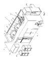
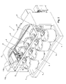
- the storage facility has an insulated outer housing 2, which encloses a chamber 3.
- a dewar 4 is arranged in the chamber 3 in the chamber 3 in the chamber 3 in the chamber 3 .
- a plurality of such Dewargefässe 4 are provided in the chamber 3 .
- Each dewar 4 has in a known manner an evacuated, mirrored insulation wall, which has low heat conduction.
- the Dewar vessels are closed on all sides in the embodiment shown and to access their interior, a cover 5 is provided in each case.
- the lid covers an opening 6 arranged on the upper side of the Dewar flask.
- the chamber 3 is preferably designed as a cooling chamber.
- Tc of the chamber 3 is advantageously below 0 ° C, especially below -20 ° C or -50 ° C. This lowering of the temperature prevents the formation of ice in the Dewar vessels 4 or on the samples.
- the storage temperature Ts in the Dewar vessels 4 is less than the chamber temperature Tc and is preferably at the mentioned "very low temperatures", i. typically at -196 ° C.
- the chamber 3 may e.g. also contain only a defined atmosphere (for example, dry air or nitrogen atmosphere), or it may be a not particularly air-conditioned storage room.
- a defined atmosphere for example, dry air or nitrogen atmosphere
- a picking device 8 is arranged in the chamber 3.
- This picking device 8 each has a transport device for the storage cassettes, the sample plates and the sample tubes. It is arranged movable above the Dewargefêt 4. How out Fig. 1 and 2 can be seen, it is advantageous exactly a picking device 8 is provided which serves all Dewar vessels.
- the storage facility further comprises a first cooling device 9a for generating the internal temperature Ti in the chamber 3 and a second cooling device 9b for generating the storage temperature Ts in the dewar vessels 4.
- the chamber 3 is accessible via a door 11 which is sufficiently large for receiving the Dewargeftreu 4.
- a positioning drive 22 serves to rotate the carousel 18 about the axis of rotation 16 and to bring it into defined positions.
- the storage cassettes 20 are arranged in several concentric circles about the axis of rotation 16, radially positioned by means of vertical walls 24 and movable in the vertical direction.
- the door 5 can be opened and closed automatically with a door drive 26. It is arranged on the upper side of the Dewar 4 and positioned and dimensioned so that with the door open 5 each storage cassette 20, which was rotated with the positioning drive 22 in the region of the door opening, can be pulled out from above.
- the horizontal diameter of the door opening is smaller than half the horizontal diameter of the Dewar flask 4, so that an excessive loss of cold when opening the door 5 can be avoided.
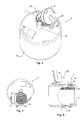
- FIG. 20 A second embodiment of a Dewar flask is in Fig. 20 shown. It is evident in Fig. 20 in particular the double wall with the vacuum insulation 12 and the lid 5 (not shown) closed opening 6.
- a carousel 18 In the interior of the Dewar is again a carousel 18, which carries on its bottom plate 19 a plurality of storage cassettes (not shown).
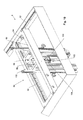
- the storage cassette forms a plurality of superimposed bearings, each of which can accommodate a sample plate. They are designed to provide high mechanical accuracy over a very wide temperature range. They also have centering and transport devices that allow high mechanical positioning accuracy and automatic transport.
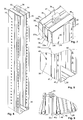
- each bearing point of several angles 40, 42 is formed. These angles form support elements and protrude inward from the side walls 30 (angle 40) and the back wall 32 (angle 42) and form side and rear supports for the sample plates.
- the angle 42 on the rear wall 32 have at its front edge bent, ie bent upwards, retaining elements 44 (see Fig. 7 ), which engage in the inserted sample plate, for example, behind a rear wall thereof, so as to prevent them from slipping forward.
- the side walls 30 of the bearing cassettes 20 are bent over at the front and thus form bent regions 46, with which the storage cassette 20 is positioned laterally in the Dewar 4.
- the bent portions 46 are each laterally on a stationary in the carousel 18 arranged holding element 48 on.
- the bent regions 46 increase the stability of the storage cassettes.
- a vertical bead 47 extends in each side wall.
- the side walls 30 and the rear wall 32 are formed by mutually bent portions of a single piece of metal sheet metal.
- the ceiling part 34 and the bottom part 38 are formed by bent portions of the same piece of sheet metal.
- the angle 40, 42 may be formed by bent portions of the sheet metal part. This simplifies the manufacture of the storage cassette and makes the storage cassette robust and temperature-resistant.
- predetermined bending points 39 in particular in the form of elongated holes or slots are provided which simplify a location-accurate bending of the sheet metal piece during manufacture.
- the outline of the piece of sheet metal is cut by laser processing, and also the predetermined bending points 39 are created in the same operation with the laser, so that a high relative position accuracy is ensured.
- the illustrated storage cassette is not only suitable for use in the storage facility described herein but also for use for other purposes, e.g. generally for storage of laboratory objects (such as microtiter plates) inside and outside of climate cabinets.
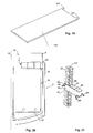
- Fig. 22 shows a laboratory object in the form of a sample plate 43, which rests on the angles 40, 42. As can be seen, at least two spaced-apart angles 40 are arranged on the side walls.
- Fig. 23 shows the sample plate 43 in a position in which its center of gravity over the front (ie feed side) angle 40 rests.
- the distance A between the angles or supporting elements 40 is selected that tilting of the plate is avoided as possible in this position.
- the distance and lengths of the support elements 40 are selected so that L / 2 - A ⁇ B .
- L is the length of the laboratory plate or the bearing (in the extension direction of the blade)
- A is the distance between the two arranged on the side wall support elements or angles 40 and B, the length of the support elements, in particular the front (ie charging side) support element or Winkels 40, is.
- At least one cassette lift 60 is arranged on the carriage 56, with which bearing cassettes can be removed from the dewar vessels 4 in the vertical direction and inserted again into them.
- two such cassette lifts 60 are provided. They are mounted rotated by 180 ° to each other. This arrangement was chosen because in the execution Fig. 1 and 2
- the Dewar vessels are arranged in two mutually rotated by 180 ° rows, so that per row of Dewar vessels a correspondingly oriented cassette lift 60 is available.
- only one cassette lift 60 could be provided, which can be rotated about a vertical axis by 180 °.
- the Dewar vessels 4 can all be the same orientation, in which case a single, non-rotatable cassette lift is sufficient.
- An envelope device 100 is further provided on the carriage 56. In the execution after Fig. 10 This handling device 100 is arranged between the two cassette lifts 60.
- the structure and function of the handling device 100 essentially correspond to those of the handling device WO 02/059251 ,
- the handling device 100 comprises a vertical guide 102, on which a folding carriage 104 is arranged to be automatically movable in the vertical direction.
- a horizontally extendable blade 106 is provided at the envelope slide 104.
- the blade 106 may preferably be pivoted about at least 180 ° about a vertical axis, so that in the embodiment of Fig. 10 optionally in the storage cassettes 20 of the opposing cassette lifts 60 retract and there record a test plate or can store. Further, it can also be pivoted in the longitudinal direction of the storage facility 1 in order to be arranged at an end in the storage facility 1 transfer station 108 (see Fig. 2 ) place or pick up a sample plate.
- a climate chamber 110 can be provided at the location of the transfer station 108, which is able to exchange laboratory objects or bearing plates with the transfer station 108.
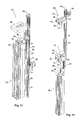
- a first telescoping section 62 is fixedly mounted on the carriage 56.
- a first vertical rail 69 is arranged, on which a first vertical drive 66 is arranged displaceably.
- the vertical drive 66 is connected via a first guide 70 to the first vertical rail 69 and engages with a pinion 72 in a rack 74 on the first telescopic section 62 a.
- a second vertical rail 76 is further arranged, on which the second telescopic section 64 is mounted vertically movable. It is connected via a deflected at the upper end of the first telescopic section 62, flexible, tensile low-temperature-resistant band or a chain 80 to the first vertical drive 66, so that lowering or raising the first vertical drive 66 a booting or lowering the second telescopic section 66 to the same height relative to the first telescopic section 62 causes.
- the second telescopic section 64 can be extended or retracted telescopically.
- a third vertical rail 82 is arranged, on which an arm 84 of the cassette lift 60 is mounted vertically movable.
- the second vertical drive 68 is configured to move the arm 84 vertically relative to the second telescoping section 64.
- the second vertical drive 68 engages with a pinion in a toothed rack 86 on the second telescopic section 64.
- a gripper device 88 is arranged with a gripper drive 89, with which the handle 36 a storage cassette 20 can be taken from above.
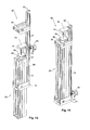
- FIGS. 15-18 show a third embodiment of a cassette lift 60. It corresponds structurally that after Fig. 12 - 14 , with the differences described below.
- the third embodiment of the cassette lift is not based on a telescopic arrangement of elements. Rather, the chain 80 together with rollers 96, 97 a pulley, which serves to lower the gripper device 88 in the Dewar 4. For this purpose, the chain is deflected over at least one lower and at least one upper roller 96 and 97, cf. Fig. 18 , One of the rollers, advantageously the lower roller 96, is displaceable in the vertical direction via the vertical drive 66, while the other roller and the upper end of the chain 80 are vertically stationary.
- the vertical drive is arranged on the first vertical rail 69 of a rail carrier 62 ( Fig. 18 ).
- the rail support 62 corresponds to the first telescopic element 62 of the preceding embodiments and is fixedly arranged on the carriage 56.
- the deflected at the upper end of the cassette lift 60 chain 80 depends vertically downwards and carries at its lower end the gripper device 88 which, as in the second embodiment of the cassette lift, is formed by an electromagnet, with which the respective storage cassette can be magnetically held.
- the gripper device 88 exemplifies the same shape as the handle 36 Fig. 6 However, it forms a separate element from the handle 36.
- the handle 36 may be omitted if the storage cassette 20 can be magnetically held at least at its upper end.
- a steel or iron plate 101 is advantageously provided at an upper end of the storage cassette 20, as in Fig. 20 is shown.
- a guide element 98 is provided which is longitudinally displaceably guided on a second vertical rail 76.
- the second vertical rail 76 is also arranged on the rail carrier 62.
- the guide member 98 forms a lateral guide for the chain 80, preferably an eyelet 116, through which the chain 80 passes.
- the guide member 98 In the lowered position of the storage cassette 20 (see. Fig. 16 ) is the guide member 98 at a stop at the lower end of the second vertical rail 76. If the storage cassette 20 is raised, so the eyelet 116 abuts the gripper 88 and is taken, see. Fig. 16 - 18 ,
- FIGS. 15-18 also has the advantage that it only requires a vertical drive 66, which can also be arranged relatively high up on the lift and does not have to be lowered into the very cold areas of the storage facility.
- the use of a pulley is also advantageous because it allows to reduce the vertical stroke of the engine and so the overall height.
- the chain or band 80 need not necessarily be arranged in a pulley.
- the gripper device 88 for gripping the storage cassettes 20 are lowered on a chain or a band 80 in the Dewar vessels.
- a centering element 95 may also be provided on the dewar 2, as shown in FIGS. 20 and 21 is shown.
- this centering element 95 will be arranged in the opening 6.
- the centering element 95 has an upwardly widening upper collar 96 and a downwardly widening lower collar 97, which simplify insertion of the storage cassette 20 from above or below. It is aligned with lateral feet 98 in the opening 6 in the correct position relative to the carousel 18 and it forms at least one guide opening 99, in which the storage cassette is guided horizontally in the implementation. Between the guide opening 99 and a storage cassette 20, the smallest possible horizontal play of eg maximum 5 mm remains.
- the centering element has a plurality of guide openings 99, which are arranged at different distances from the axis of rotation 16.
- the distances of the guide openings 99 to the axis of rotation 16 correspond to the radii of the circles of the storage shafts in the carousel 18.
- the rear wall 32 of the storage cassettes 20 is constructed so that the holding elements 107 find space to be brought from below behind a held in the storage cassette 20 laboratory object.
- the rear wall 32 as in Fig. 7 shown in two vertically extending side regions 32a set back relative to its central region 32b.
- a first region (middle region 32b) of the rear wall 32 forms a spacer, with respect to which at least one second region (in FIG Fig. 7 the side portions 32a) is recessed, such that the holding members 107 are insertable behind the stored in the storage cassette laboratory objects in the recessed or a corresponding recessed area, ie that the holding elements 107 find space behind the held in the storage cassette laboratory object.
- the storage facility 1 and the storage cassettes 20 serve for the storage of sample tubes.
- samples in other forms, generally suitable for the storage of laboratory objects. These may be, for example, biological or chemical samples.
- a typical application also concerns the storage of laboratory samples in microtiter plates, in which case the sample plates are designed as microtiter plates.
- sample containers eg bottles are used, which each contain only one sample.
Applications Claiming Priority (1)
| Application Number | Priority Date | Filing Date | Title |
|---|---|---|---|
| CH01968/10A CH704128A1 (de) | 2010-11-24 | 2010-11-24 | Lageranlage für tiefe Temperaturen und Lagerkassette für Laborobjekte. |
Publications (3)
| Publication Number | Publication Date |
|---|---|
| EP2458309A2 true EP2458309A2 (fr) | 2012-05-30 |
| EP2458309A3 EP2458309A3 (fr) | 2015-07-15 |
| EP2458309B1 EP2458309B1 (fr) | 2019-08-07 |
Family
ID=45098787
Family Applications (4)
| Application Number | Title | Priority Date | Filing Date |
|---|---|---|---|
| EP11009208.7A Active EP2458308B1 (fr) | 2010-11-24 | 2011-11-21 | Installation de stockage d'objets de laboratoire à basses températures |
| EP11009209.5A Active EP2458309B1 (fr) | 2010-11-24 | 2011-11-21 | Caisson de stockage pour objets de laboratoire |
| EP20215024.9A Active EP3812674B1 (fr) | 2010-11-24 | 2011-11-21 | Entrepôt destiné à l'entreposage des objets de laboratoire à basses températures |
| EP19185530.3A Active EP3581864B1 (fr) | 2010-11-24 | 2011-11-21 | Installation de stockage d'objets de laboratoire à basses températures |
Family Applications Before (1)
| Application Number | Title | Priority Date | Filing Date |
|---|---|---|---|
| EP11009208.7A Active EP2458308B1 (fr) | 2010-11-24 | 2011-11-21 | Installation de stockage d'objets de laboratoire à basses températures |
Family Applications After (2)
| Application Number | Title | Priority Date | Filing Date |
|---|---|---|---|
| EP20215024.9A Active EP3812674B1 (fr) | 2010-11-24 | 2011-11-21 | Entrepôt destiné à l'entreposage des objets de laboratoire à basses températures |
| EP19185530.3A Active EP3581864B1 (fr) | 2010-11-24 | 2011-11-21 | Installation de stockage d'objets de laboratoire à basses températures |
Country Status (3)
| Country | Link |
|---|---|
| US (2) | US9784495B2 (fr) |
| EP (4) | EP2458308B1 (fr) |
| CH (1) | CH704128A1 (fr) |
Cited By (1)
| Publication number | Priority date | Publication date | Assignee | Title |
|---|---|---|---|---|
| CN106560419A (zh) * | 2016-11-14 | 2017-04-12 | 上海原能细胞医学技术有限公司 | 管阵式液氮罐 |
Families Citing this family (27)
| Publication number | Priority date | Publication date | Assignee | Title |
|---|---|---|---|---|
| US9995525B2 (en) * | 2009-01-19 | 2018-06-12 | Liconic Ag | Low-temperature automated storage for laboratory samples with automated access |
| JP5346127B2 (ja) * | 2009-10-19 | 2013-11-20 | ネクサス バイオシステムズ,インコーポレイテッド | モジュール式試料貯蔵装置 |
| WO2015018816A1 (fr) * | 2013-08-08 | 2015-02-12 | Sanofi-Aventis Deutschland Gmbh | Ensemble de récupération pour applications de cryoconservation |
| WO2015085287A1 (fr) * | 2013-12-07 | 2015-06-11 | Trumed Systems, Inc. | Stockage intelligent automatisé de produits thermosensibles |
| US20150291357A1 (en) * | 2014-04-14 | 2015-10-15 | Sergey N. Razumov | Robotic pickup point for order fulfillment system |
| EP2998669B1 (fr) | 2014-09-22 | 2018-09-05 | Liconic Ag | Dispositif de stockage à basse température avec élément de manipulation de cassette |
| EP3006867B1 (fr) | 2014-09-22 | 2017-08-23 | Liconic Ag | Dispositif de stockage à basse température avec chambre à verrou rotatif |
| CN104773425B (zh) * | 2015-03-24 | 2017-03-22 | 苏州优点优唯医疗科技有限公司 | 一种智能冷链储物库 |
| CN107567572B (zh) | 2015-03-30 | 2021-05-25 | 布鲁克斯自动化公司 | 低温冷冻机 |
| EP4191169A1 (fr) * | 2015-03-30 | 2023-06-07 | Azenta, Inc. | Système de stockage cryogénique automatisé |
| EP3353479B1 (fr) * | 2015-09-24 | 2021-11-10 | Liconic Ag | Dispositif de stockage à basse température et de manutention de tubes-sondes dans des supports de tubes |
| CN105857941B (zh) * | 2016-04-28 | 2018-06-29 | 上海原能健康管理有限公司 | 冻存管存取装置 |
| CN105857937B (zh) * | 2016-04-28 | 2018-05-08 | 上海原能健康管理有限公司 | 冻存管存取装置以及液氮罐存取系统 |
| CN105857932B (zh) * | 2016-04-28 | 2018-02-13 | 上海原能健康管理有限公司 | 冻存管存取装置 |
| CN106628783B (zh) * | 2016-12-28 | 2022-04-29 | 上海原能细胞生物低温设备有限公司 | 全自动超低温蜂巢型生物样本库 |
| CN107062731A (zh) * | 2017-02-20 | 2017-08-18 | 上海原能细胞医学技术有限公司 | 自动化存储装置及其运行方法 |
| EP3467408B1 (fr) | 2017-10-05 | 2024-02-21 | Liconic AG | Méthode de fonctionnement d'une installation de stockage à basse température ayant un appareil de retrait d'azote dans un bâtiment |
| CN109928071A (zh) * | 2017-12-15 | 2019-06-25 | 国玺干细胞应用技术股份有限公司 | 智能科技生物产品低温储存设备 |
| CN109275657B (zh) * | 2018-09-17 | 2023-07-04 | 上海原能细胞生物低温设备有限公司 | 一种螺旋升降式低温存储装置 |
| CN209480359U (zh) * | 2018-12-27 | 2019-10-11 | 上海原能细胞生物低温设备有限公司 | 一种液氮罐 |
| EP3969827A1 (fr) * | 2019-05-13 | 2022-03-23 | ABT Holding Company | Appareil et procédé de cryostockage et de manutention d'une pluralité d'unités de conteneur |
| CN112705285A (zh) * | 2020-12-29 | 2021-04-27 | 陈文强 | 一种医院检验科专用样本储放转移装置 |
| CN112705286A (zh) * | 2020-12-29 | 2021-04-27 | 陈文强 | 一种医院检验科医疗样本存储箱 |
| CN112705287A (zh) * | 2020-12-29 | 2021-04-27 | 陈文强 | 一种医用多功能收储工作台 |
| CN112452380A (zh) * | 2020-12-29 | 2021-03-09 | 陈文强 | 一种医院检验科多位一体工作台 |
| CN113501247A (zh) * | 2021-08-26 | 2021-10-15 | 义乌市铂玥信息技术咨询有限公司 | 转笼式超低温生物样本自动化存取系统 |
| FR3140876A1 (fr) * | 2022-10-13 | 2024-04-19 | Exotec | Organe longiligne présentant au moins une crémaillère, rack de stockage comprenant un tel organe longiligne, et système de transport et de stockage comprenant un tel rack de stockage |
Citations (1)
| Publication number | Priority date | Publication date | Assignee | Title |
|---|---|---|---|---|
| WO2002059251A2 (fr) | 2001-01-26 | 2002-08-01 | Liconic Ag | Armoire de stockage climatisee |
Family Cites Families (47)
| Publication number | Priority date | Publication date | Assignee | Title |
|---|---|---|---|---|
| US3272579A (en) | 1964-08-24 | 1966-09-13 | Cryogenic Eng Co | Cryogenic storage vessel with station selector |
| US3782133A (en) | 1972-08-14 | 1974-01-01 | Air Liquide | Low temperature storage vessel |
| US4250266A (en) | 1979-12-19 | 1981-02-10 | Honeywell Inc. | Automated micro-organism culture growth and detection instrument |
| US4771900A (en) * | 1987-04-09 | 1988-09-20 | Nalge Company | Storage rack for box-like container |
| US4907889A (en) | 1988-03-24 | 1990-03-13 | Automation Equipment Company | Video cassette library retrieval and sequencing system |
| US4832195A (en) * | 1988-05-02 | 1989-05-23 | Dahl Ernest A | Compact storage files |
| US4969336A (en) * | 1989-08-04 | 1990-11-13 | Cryo-Cell International, Inc. | Cryogenic storage apparatus, particularly with automatic retrieval |
| US5131250A (en) | 1991-02-08 | 1992-07-21 | The National Machinery Company | Flat die thread roller |
| US5192506A (en) | 1991-02-14 | 1993-03-09 | P B Diagnostic Systems, Inc. | Incubator port closure for automated assay system |
| US5233844A (en) | 1991-08-15 | 1993-08-10 | Cryo-Cell International, Inc. | Storage apparatus, particularly with automatic insertion and retrieval |
| FR2680658B1 (fr) * | 1991-08-30 | 1993-11-19 | Air Liquide | Panier de rangement de boitiers individuels et conteneur cryogenique. |
| US5266272A (en) | 1991-10-31 | 1993-11-30 | Baxter Diagnostics Inc. | Specimen processing and analyzing systems with a station for holding specimen trays during processing |
| AU656826B2 (en) | 1991-10-31 | 1995-02-16 | Microscan, Inc. | Specimen processing and analyzing systems with associated fluid dispensing apparatus |
| US5345395A (en) | 1991-10-31 | 1994-09-06 | Baxter Diagnostics Inc. | Specimen processing and analyzing systems and methods using photometry |
| US5240139A (en) | 1992-03-06 | 1993-08-31 | Munroe Chirnomas | Package vending machine |
| US5735587A (en) | 1995-02-06 | 1998-04-07 | Liconic Ag | Climatic cabinet, turntable and use of the turntable |
| SE9602404D0 (sv) | 1996-06-18 | 1996-06-18 | Jan Dranger | Furniture device |
| US6129428A (en) | 1996-08-05 | 2000-10-10 | Kendro Laboratory Products Gmbh | Storage device for objects, storage station and air-conditioned cabinet |
| US5921102A (en) | 1997-03-28 | 1999-07-13 | Cryo-Cell International, Inc. | Storage apparatus particularly with automatic insertion and retrieval |
| US6068393A (en) | 1997-11-05 | 2000-05-30 | Zymark Corporation | Robotic system for processing chemical products |
| CH690645C1 (de) | 1999-09-02 | 2002-08-30 | Liconic Ag | LAGERANLAGE UND LAGERBEHäLTNIS MIT LAGERANLAGE |
| AU2001257343A1 (en) | 2000-04-28 | 2001-11-12 | Biocrystal Ltd. | Holder for cell culture devices |
| DE10024581A1 (de) * | 2000-05-19 | 2001-11-29 | Kendro Lab Prod Gmbh | Klimaschrank |
| DE10058564A1 (de) | 2000-11-24 | 2002-06-06 | Kendro Lab Prod Gmbh | Objektlagerstation und Klimaschrank |
| GB0209025D0 (en) | 2002-04-19 | 2002-05-29 | Randox Lab Ltd | Assay device incubator |
| US6694767B2 (en) * | 2002-06-19 | 2004-02-24 | Jouan | Work enclosure having article supports that obstruct access openings |
| ITBO20020607A1 (it) | 2002-09-26 | 2004-03-27 | Cryorobotics | Sistema automatico per la conservazione a temperatura |
| EP1441026B1 (fr) | 2003-01-10 | 2012-10-17 | Liconic Ag | Système de stockage automatique et armoire de climatisation avec un tel système de stockage automatique |
| DE10332799B4 (de) * | 2003-07-18 | 2007-03-01 | Fraunhofer-Gesellschaft zur Förderung der angewandten Forschung e.V. | Vorrichtung und Verfahren zur Handhabung einer Probe |
| JP2005143873A (ja) | 2003-11-17 | 2005-06-09 | Taiyo Nippon Sanso Corp | 凍結保存容器 |
| DE102004008496B3 (de) | 2004-02-20 | 2005-07-14 | Fraunhofer-Gesellschaft zur Förderung der angewandten Forschung e.V. | Verschluss für eine Kühlbehälteröffnung |
| US20060006774A1 (en) | 2004-07-09 | 2006-01-12 | Kendro Laboratory Products, Lp | Microplate storage apparatus and method |
| EP1634496A1 (fr) * | 2004-09-14 | 2006-03-15 | The Automation Partnership (Cambridge) Limited | Systeme de stockage a temperature ultra-basse |
| US20060150659A1 (en) | 2004-12-10 | 2006-07-13 | Sidor Michael R | Vertical storage systems |
| DE102005001888A1 (de) | 2005-01-14 | 2006-07-20 | Liconic Ag | Automatische Lagervorrichtung und Klimaschrank für Laborgüter |
| EP1836292B1 (fr) | 2005-01-14 | 2017-11-22 | Liconic Ag | Dispositif de stockage automatique et armoire climatique pour articles de laboratoire |
| DK177390B1 (da) | 2006-03-13 | 2013-03-04 | Teddy Kristensen | Udgangsemne til en reol |
| DE102007004072A1 (de) | 2007-01-26 | 2008-07-31 | Thermo Electron Led Gmbh | Objektlagervorrichtung mit Schüttelfunktion |
| EP1972874B1 (fr) | 2007-03-20 | 2019-02-13 | Liconic Ag | Stockage de substances automatisé |
| EP1975626A1 (fr) * | 2007-03-29 | 2008-10-01 | F. Hoffmann-Roche AG | Empileuse pour des plaques à microtitre |
| US20090140616A1 (en) | 2007-12-04 | 2009-06-04 | Anthony Fox | Trash compactor cabinet |
| EP2078961B1 (fr) | 2008-01-08 | 2020-04-08 | Liconic Ag | Dispositif de manipulation d'échantillons de laboratoire |
| JP4648444B2 (ja) * | 2008-01-18 | 2011-03-09 | 大陽日酸株式会社 | グローブボックス |
| DE102008057981B4 (de) | 2008-11-19 | 2010-09-02 | Fraunhofer-Gesellschaft zur Förderung der angewandten Forschung e.V. | Kryospeichereinrichtung |
| IT1408715B1 (it) * | 2008-12-17 | 2014-07-03 | Parmegiani | Dispositivo e metodo per la sterilizzazione di azoto liquido in fase liquida mediante radiazione ultravioletta. |
| US9995525B2 (en) | 2009-01-19 | 2018-06-12 | Liconic Ag | Low-temperature automated storage for laboratory samples with automated access |
| US9255936B2 (en) * | 2010-09-10 | 2016-02-09 | Hamilton Storage Technologies, Inc. | Sample storage cassette for ultra-low or cryogenic temperatures |
-
2010
- 2010-11-24 CH CH01968/10A patent/CH704128A1/de not_active Application Discontinuation
-
2011
- 2011-11-21 EP EP11009208.7A patent/EP2458308B1/fr active Active
- 2011-11-21 EP EP11009209.5A patent/EP2458309B1/fr active Active
- 2011-11-21 EP EP20215024.9A patent/EP3812674B1/fr active Active
- 2011-11-21 EP EP19185530.3A patent/EP3581864B1/fr active Active
- 2011-11-23 US US13/304,098 patent/US9784495B2/en active Active
- 2011-11-23 US US13/304,079 patent/US9005542B2/en active Active
Patent Citations (1)
| Publication number | Priority date | Publication date | Assignee | Title |
|---|---|---|---|---|
| WO2002059251A2 (fr) | 2001-01-26 | 2002-08-01 | Liconic Ag | Armoire de stockage climatisee |
Cited By (2)
| Publication number | Priority date | Publication date | Assignee | Title |
|---|---|---|---|---|
| CN106560419A (zh) * | 2016-11-14 | 2017-04-12 | 上海原能细胞医学技术有限公司 | 管阵式液氮罐 |
| CN106560419B (zh) * | 2016-11-14 | 2018-10-19 | 上海原能细胞医学技术有限公司 | 管阵式液氮罐 |
Also Published As
| Publication number | Publication date |
|---|---|
| CH704128A1 (de) | 2012-05-31 |
| EP2458309B1 (fr) | 2019-08-07 |
| EP3812674A1 (fr) | 2021-04-28 |
| EP3581864A1 (fr) | 2019-12-18 |
| US20120134897A1 (en) | 2012-05-31 |
| US20120134898A1 (en) | 2012-05-31 |
| EP2458308A3 (fr) | 2015-07-15 |
| US9005542B2 (en) | 2015-04-14 |
| EP2458308A2 (fr) | 2012-05-30 |
| EP3581864B1 (fr) | 2021-01-06 |
| EP2458309A3 (fr) | 2015-07-15 |
| US9784495B2 (en) | 2017-10-10 |
| EP2458308B1 (fr) | 2019-08-14 |
| EP3812674B1 (fr) | 2022-04-13 |
Similar Documents
| Publication | Publication Date | Title |
|---|---|---|
| EP2458309B1 (fr) | Caisson de stockage pour objets de laboratoire | |
| EP2743614B1 (fr) | Caisson de stockage pour objets de laboratoire | |
| EP1836292B1 (fr) | Dispositif de stockage automatique et armoire climatique pour articles de laboratoire | |
| DE112014001610B4 (de) | Kühlschrank | |
| WO2006074568A1 (fr) | Dispositif de stockage automatique et armoire climatique pour articles de laboratoire | |
| EP2019278B1 (fr) | Dispositif de charge et de décharge d'une plaque réglable d'une installation de lyophilisation | |
| DE102011012887A1 (de) | Kryospeichereinrichtung | |
| EP1939561A2 (fr) | Systeme de stockage compact et son utilisation | |
| DE102013009340A1 (de) | Einrichtung und Verfahren zum Ein- und Auslagern von stapelbaren Behältern | |
| EP1972874A2 (fr) | Stockage de substances automatisé | |
| EP1441026A1 (fr) | Système de stockage automatique et armoire de climatisation avec un tel système de stockage automatique | |
| DE4036970A1 (de) | Ausziehstuetzvorrichtung | |
| EP3285930B1 (fr) | Support pour la réception et pour le rangement de récipients de laboratoire | |
| DE10202873A1 (de) | Objekt-Lagervorrichtung und Klimaschrank | |
| DE102015201565A1 (de) | Kommissioniervorrichtung in Form eines Drehtisches | |
| EP3658339A1 (fr) | Boîte de rangement et rayonnage | |
| DE102012220193A1 (de) | Lagergut-Extraktor für ein automatisches Lagersystem | |
| DE102004053170A1 (de) | Lagerungssystem | |
| DE102008061204B3 (de) | Magazin zur Lagerung von Twist-Locks | |
| CH708425B1 (de) | Lageranlage zur Lagerung von Objekten. | |
| DE102016124722B4 (de) | Handhabungseinrichtung, insbesondere für eine Lagerungsvorrichtung | |
| DE102008019384A1 (de) | Ausziehbarer Eierhalter und Kühlgerät mit einem solchen Halter | |
| DE102006038149B4 (de) | Brenngestellaufbau aus mindestens einem Brenngestell | |
| DE202008013492U1 (de) | Klimaschrank mit zwei Ein- und Ausgabestationen | |
| DE102016006724A1 (de) | Fahrzeug mit einem Ladungsträger-Organisationssystem |
Legal Events
| Date | Code | Title | Description |
|---|---|---|---|
| PUAI | Public reference made under article 153(3) epc to a published international application that has entered the european phase |
Free format text: ORIGINAL CODE: 0009012 |
|
| AK | Designated contracting states |
Kind code of ref document: A2 Designated state(s): AL AT BE BG CH CY CZ DE DK EE ES FI FR GB GR HR HU IE IS IT LI LT LU LV MC MK MT NL NO PL PT RO RS SE SI SK SM TR |
|
| AX | Request for extension of the european patent |
Extension state: BA ME |
|
| PUAL | Search report despatched |
Free format text: ORIGINAL CODE: 0009013 |
|
| AK | Designated contracting states |
Kind code of ref document: A3 Designated state(s): AL AT BE BG CH CY CZ DE DK EE ES FI FR GB GR HR HU IE IS IT LI LT LU LV MC MK MT NL NO PL PT RO RS SE SI SK SM TR |
|
| AX | Request for extension of the european patent |
Extension state: BA ME |
|
| RIC1 | Information provided on ipc code assigned before grant |
Ipc: F25D 25/00 20060101AFI20150608BHEP |
|
| 17P | Request for examination filed |
Effective date: 20160108 |
|
| RBV | Designated contracting states (corrected) |
Designated state(s): AL AT BE BG CH CY CZ DE DK EE ES FI FR GB GR HR HU IE IS IT LI LT LU LV MC MK MT NL NO PL PT RO RS SE SI SK SM TR |
|
| GRAP | Despatch of communication of intention to grant a patent |
Free format text: ORIGINAL CODE: EPIDOSNIGR1 |
|
| STAA | Information on the status of an ep patent application or granted ep patent |
Free format text: STATUS: GRANT OF PATENT IS INTENDED |
|
| INTG | Intention to grant announced |
Effective date: 20190319 |
|
| GRAS | Grant fee paid |
Free format text: ORIGINAL CODE: EPIDOSNIGR3 |
|
| GRAA | (expected) grant |
Free format text: ORIGINAL CODE: 0009210 |
|
| STAA | Information on the status of an ep patent application or granted ep patent |
Free format text: STATUS: THE PATENT HAS BEEN GRANTED |
|
| AK | Designated contracting states |
Kind code of ref document: B1 Designated state(s): AL AT BE BG CH CY CZ DE DK EE ES FI FR GB GR HR HU IE IS IT LI LT LU LV MC MK MT NL NO PL PT RO RS SE SI SK SM TR |
|
| REG | Reference to a national code |
Ref country code: GB Ref legal event code: FG4D Free format text: NOT ENGLISH |
|
| REG | Reference to a national code |
Ref country code: CH Ref legal event code: EP Ref country code: AT Ref legal event code: REF Ref document number: 1164513 Country of ref document: AT Kind code of ref document: T Effective date: 20190815 |
|
| REG | Reference to a national code |
Ref country code: DE Ref legal event code: R096 Ref document number: 502011015966 Country of ref document: DE |
|
| REG | Reference to a national code |
Ref country code: IE Ref legal event code: FG4D Free format text: LANGUAGE OF EP DOCUMENT: GERMAN |
|
| REG | Reference to a national code |
Ref country code: NL Ref legal event code: MP Effective date: 20190807 |
|
| REG | Reference to a national code |
Ref country code: LT Ref legal event code: MG4D |
|
| PG25 | Lapsed in a contracting state [announced via postgrant information from national office to epo] |
Ref country code: FI Free format text: LAPSE BECAUSE OF FAILURE TO SUBMIT A TRANSLATION OF THE DESCRIPTION OR TO PAY THE FEE WITHIN THE PRESCRIBED TIME-LIMIT Effective date: 20190807 Ref country code: PT Free format text: LAPSE BECAUSE OF FAILURE TO SUBMIT A TRANSLATION OF THE DESCRIPTION OR TO PAY THE FEE WITHIN THE PRESCRIBED TIME-LIMIT Effective date: 20191209 Ref country code: SE Free format text: LAPSE BECAUSE OF FAILURE TO SUBMIT A TRANSLATION OF THE DESCRIPTION OR TO PAY THE FEE WITHIN THE PRESCRIBED TIME-LIMIT Effective date: 20190807 Ref country code: HR Free format text: LAPSE BECAUSE OF FAILURE TO SUBMIT A TRANSLATION OF THE DESCRIPTION OR TO PAY THE FEE WITHIN THE PRESCRIBED TIME-LIMIT Effective date: 20190807 Ref country code: NL Free format text: LAPSE BECAUSE OF FAILURE TO SUBMIT A TRANSLATION OF THE DESCRIPTION OR TO PAY THE FEE WITHIN THE PRESCRIBED TIME-LIMIT Effective date: 20190807 Ref country code: LT Free format text: LAPSE BECAUSE OF FAILURE TO SUBMIT A TRANSLATION OF THE DESCRIPTION OR TO PAY THE FEE WITHIN THE PRESCRIBED TIME-LIMIT Effective date: 20190807 Ref country code: NO Free format text: LAPSE BECAUSE OF FAILURE TO SUBMIT A TRANSLATION OF THE DESCRIPTION OR TO PAY THE FEE WITHIN THE PRESCRIBED TIME-LIMIT Effective date: 20191107 Ref country code: BG Free format text: LAPSE BECAUSE OF FAILURE TO SUBMIT A TRANSLATION OF THE DESCRIPTION OR TO PAY THE FEE WITHIN THE PRESCRIBED TIME-LIMIT Effective date: 20191107 |
|
| PG25 | Lapsed in a contracting state [announced via postgrant information from national office to epo] |
Ref country code: AL Free format text: LAPSE BECAUSE OF FAILURE TO SUBMIT A TRANSLATION OF THE DESCRIPTION OR TO PAY THE FEE WITHIN THE PRESCRIBED TIME-LIMIT Effective date: 20190807 Ref country code: ES Free format text: LAPSE BECAUSE OF FAILURE TO SUBMIT A TRANSLATION OF THE DESCRIPTION OR TO PAY THE FEE WITHIN THE PRESCRIBED TIME-LIMIT Effective date: 20190807 Ref country code: IS Free format text: LAPSE BECAUSE OF FAILURE TO SUBMIT A TRANSLATION OF THE DESCRIPTION OR TO PAY THE FEE WITHIN THE PRESCRIBED TIME-LIMIT Effective date: 20191207 Ref country code: RS Free format text: LAPSE BECAUSE OF FAILURE TO SUBMIT A TRANSLATION OF THE DESCRIPTION OR TO PAY THE FEE WITHIN THE PRESCRIBED TIME-LIMIT Effective date: 20190807 Ref country code: LV Free format text: LAPSE BECAUSE OF FAILURE TO SUBMIT A TRANSLATION OF THE DESCRIPTION OR TO PAY THE FEE WITHIN THE PRESCRIBED TIME-LIMIT Effective date: 20190807 Ref country code: GR Free format text: LAPSE BECAUSE OF FAILURE TO SUBMIT A TRANSLATION OF THE DESCRIPTION OR TO PAY THE FEE WITHIN THE PRESCRIBED TIME-LIMIT Effective date: 20191108 |
|
| PG25 | Lapsed in a contracting state [announced via postgrant information from national office to epo] |
Ref country code: TR Free format text: LAPSE BECAUSE OF FAILURE TO SUBMIT A TRANSLATION OF THE DESCRIPTION OR TO PAY THE FEE WITHIN THE PRESCRIBED TIME-LIMIT Effective date: 20190807 |
|
| PG25 | Lapsed in a contracting state [announced via postgrant information from national office to epo] |
Ref country code: IT Free format text: LAPSE BECAUSE OF FAILURE TO SUBMIT A TRANSLATION OF THE DESCRIPTION OR TO PAY THE FEE WITHIN THE PRESCRIBED TIME-LIMIT Effective date: 20190807 Ref country code: RO Free format text: LAPSE BECAUSE OF FAILURE TO SUBMIT A TRANSLATION OF THE DESCRIPTION OR TO PAY THE FEE WITHIN THE PRESCRIBED TIME-LIMIT Effective date: 20190807 Ref country code: PL Free format text: LAPSE BECAUSE OF FAILURE TO SUBMIT A TRANSLATION OF THE DESCRIPTION OR TO PAY THE FEE WITHIN THE PRESCRIBED TIME-LIMIT Effective date: 20190807 Ref country code: EE Free format text: LAPSE BECAUSE OF FAILURE TO SUBMIT A TRANSLATION OF THE DESCRIPTION OR TO PAY THE FEE WITHIN THE PRESCRIBED TIME-LIMIT Effective date: 20190807 Ref country code: DK Free format text: LAPSE BECAUSE OF FAILURE TO SUBMIT A TRANSLATION OF THE DESCRIPTION OR TO PAY THE FEE WITHIN THE PRESCRIBED TIME-LIMIT Effective date: 20190807 |
|
| PG25 | Lapsed in a contracting state [announced via postgrant information from national office to epo] |
Ref country code: CZ Free format text: LAPSE BECAUSE OF FAILURE TO SUBMIT A TRANSLATION OF THE DESCRIPTION OR TO PAY THE FEE WITHIN THE PRESCRIBED TIME-LIMIT Effective date: 20190807 Ref country code: SK Free format text: LAPSE BECAUSE OF FAILURE TO SUBMIT A TRANSLATION OF THE DESCRIPTION OR TO PAY THE FEE WITHIN THE PRESCRIBED TIME-LIMIT Effective date: 20190807 Ref country code: SM Free format text: LAPSE BECAUSE OF FAILURE TO SUBMIT A TRANSLATION OF THE DESCRIPTION OR TO PAY THE FEE WITHIN THE PRESCRIBED TIME-LIMIT Effective date: 20190807 Ref country code: IS Free format text: LAPSE BECAUSE OF FAILURE TO SUBMIT A TRANSLATION OF THE DESCRIPTION OR TO PAY THE FEE WITHIN THE PRESCRIBED TIME-LIMIT Effective date: 20200224 |
|
| REG | Reference to a national code |
Ref country code: DE Ref legal event code: R097 Ref document number: 502011015966 Country of ref document: DE |
|
| PLBE | No opposition filed within time limit |
Free format text: ORIGINAL CODE: 0009261 |
|
| STAA | Information on the status of an ep patent application or granted ep patent |
Free format text: STATUS: NO OPPOSITION FILED WITHIN TIME LIMIT |
|
| PG2D | Information on lapse in contracting state deleted |
Ref country code: IS |
|
| PG25 | Lapsed in a contracting state [announced via postgrant information from national office to epo] |
Ref country code: LU Free format text: LAPSE BECAUSE OF NON-PAYMENT OF DUE FEES Effective date: 20191121 Ref country code: MC Free format text: LAPSE BECAUSE OF FAILURE TO SUBMIT A TRANSLATION OF THE DESCRIPTION OR TO PAY THE FEE WITHIN THE PRESCRIBED TIME-LIMIT Effective date: 20190807 |
|
| 26N | No opposition filed |
Effective date: 20200603 |
|
| REG | Reference to a national code |
Ref country code: BE Ref legal event code: MM Effective date: 20191130 |
|
| PG25 | Lapsed in a contracting state [announced via postgrant information from national office to epo] |
Ref country code: SI Free format text: LAPSE BECAUSE OF FAILURE TO SUBMIT A TRANSLATION OF THE DESCRIPTION OR TO PAY THE FEE WITHIN THE PRESCRIBED TIME-LIMIT Effective date: 20190807 |
|
| PG25 | Lapsed in a contracting state [announced via postgrant information from national office to epo] |
Ref country code: IE Free format text: LAPSE BECAUSE OF NON-PAYMENT OF DUE FEES Effective date: 20191121 |
|
| PG25 | Lapsed in a contracting state [announced via postgrant information from national office to epo] |
Ref country code: BE Free format text: LAPSE BECAUSE OF NON-PAYMENT OF DUE FEES Effective date: 20191130 |
|
| REG | Reference to a national code |
Ref country code: AT Ref legal event code: MM01 Ref document number: 1164513 Country of ref document: AT Kind code of ref document: T Effective date: 20191121 |
|
| PG25 | Lapsed in a contracting state [announced via postgrant information from national office to epo] |
Ref country code: AT Free format text: LAPSE BECAUSE OF NON-PAYMENT OF DUE FEES Effective date: 20191121 |
|
| PG25 | Lapsed in a contracting state [announced via postgrant information from national office to epo] |
Ref country code: CY Free format text: LAPSE BECAUSE OF FAILURE TO SUBMIT A TRANSLATION OF THE DESCRIPTION OR TO PAY THE FEE WITHIN THE PRESCRIBED TIME-LIMIT Effective date: 20190807 |
|
| PG25 | Lapsed in a contracting state [announced via postgrant information from national office to epo] |
Ref country code: HU Free format text: LAPSE BECAUSE OF FAILURE TO SUBMIT A TRANSLATION OF THE DESCRIPTION OR TO PAY THE FEE WITHIN THE PRESCRIBED TIME-LIMIT; INVALID AB INITIO Effective date: 20111121 Ref country code: MT Free format text: LAPSE BECAUSE OF FAILURE TO SUBMIT A TRANSLATION OF THE DESCRIPTION OR TO PAY THE FEE WITHIN THE PRESCRIBED TIME-LIMIT Effective date: 20190807 |
|
| PG25 | Lapsed in a contracting state [announced via postgrant information from national office to epo] |
Ref country code: MK Free format text: LAPSE BECAUSE OF FAILURE TO SUBMIT A TRANSLATION OF THE DESCRIPTION OR TO PAY THE FEE WITHIN THE PRESCRIBED TIME-LIMIT Effective date: 20190807 |
|
| PGFP | Annual fee paid to national office [announced via postgrant information from national office to epo] |
Ref country code: GB Payment date: 20231123 Year of fee payment: 13 |
|
| PGFP | Annual fee paid to national office [announced via postgrant information from national office to epo] |
Ref country code: FR Payment date: 20231120 Year of fee payment: 13 Ref country code: DE Payment date: 20231121 Year of fee payment: 13 Ref country code: CH Payment date: 20231201 Year of fee payment: 13 |