EP2454506B1 - Mehrweghahn und verfahren zu dessen herstellung - Google Patents
Mehrweghahn und verfahren zu dessen herstellung Download PDFInfo
- Publication number
- EP2454506B1 EP2454506B1 EP10742107.5A EP10742107A EP2454506B1 EP 2454506 B1 EP2454506 B1 EP 2454506B1 EP 10742107 A EP10742107 A EP 10742107A EP 2454506 B1 EP2454506 B1 EP 2454506B1
- Authority
- EP
- European Patent Office
- Prior art keywords
- actuator
- way valve
- accordance
- receptacle
- basic housing
- Prior art date
- Legal status (The legal status is an assumption and is not a legal conclusion. Google has not performed a legal analysis and makes no representation as to the accuracy of the status listed.)
- Active
Links
Images
Classifications
-
- F—MECHANICAL ENGINEERING; LIGHTING; HEATING; WEAPONS; BLASTING
- F16—ENGINEERING ELEMENTS AND UNITS; GENERAL MEASURES FOR PRODUCING AND MAINTAINING EFFECTIVE FUNCTIONING OF MACHINES OR INSTALLATIONS; THERMAL INSULATION IN GENERAL
- F16K—VALVES; TAPS; COCKS; ACTUATING-FLOATS; DEVICES FOR VENTING OR AERATING
- F16K11/00—Multiple-way valves, e.g. mixing valves; Pipe fittings incorporating such valves
- F16K11/02—Multiple-way valves, e.g. mixing valves; Pipe fittings incorporating such valves with all movable sealing faces moving as one unit
- F16K11/08—Multiple-way valves, e.g. mixing valves; Pipe fittings incorporating such valves with all movable sealing faces moving as one unit comprising only taps or cocks
- F16K11/085—Multiple-way valves, e.g. mixing valves; Pipe fittings incorporating such valves with all movable sealing faces moving as one unit comprising only taps or cocks with cylindrical plug
- F16K11/0853—Multiple-way valves, e.g. mixing valves; Pipe fittings incorporating such valves with all movable sealing faces moving as one unit comprising only taps or cocks with cylindrical plug having all the connecting conduits situated in a single plane perpendicular to the axis of the plug
-
- A—HUMAN NECESSITIES
- A61—MEDICAL OR VETERINARY SCIENCE; HYGIENE
- A61M—DEVICES FOR INTRODUCING MEDIA INTO, OR ONTO, THE BODY; DEVICES FOR TRANSDUCING BODY MEDIA OR FOR TAKING MEDIA FROM THE BODY; DEVICES FOR PRODUCING OR ENDING SLEEP OR STUPOR
- A61M39/00—Tubes, tube connectors, tube couplings, valves, access sites or the like, specially adapted for medical use
- A61M39/22—Valves or arrangement of valves
- A61M39/223—Multiway valves
-
- F—MECHANICAL ENGINEERING; LIGHTING; HEATING; WEAPONS; BLASTING
- F16—ENGINEERING ELEMENTS AND UNITS; GENERAL MEASURES FOR PRODUCING AND MAINTAINING EFFECTIVE FUNCTIONING OF MACHINES OR INSTALLATIONS; THERMAL INSULATION IN GENERAL
- F16K—VALVES; TAPS; COCKS; ACTUATING-FLOATS; DEVICES FOR VENTING OR AERATING
- F16K27/00—Construction of housing; Use of materials therefor
- F16K27/06—Construction of housing; Use of materials therefor of taps or cocks
- F16K27/065—Construction of housing; Use of materials therefor of taps or cocks with cylindrical plugs
-
- A—HUMAN NECESSITIES
- A61—MEDICAL OR VETERINARY SCIENCE; HYGIENE
- A61M—DEVICES FOR INTRODUCING MEDIA INTO, OR ONTO, THE BODY; DEVICES FOR TRANSDUCING BODY MEDIA OR FOR TAKING MEDIA FROM THE BODY; DEVICES FOR PRODUCING OR ENDING SLEEP OR STUPOR
- A61M2205/00—General characteristics of the apparatus
- A61M2205/02—General characteristics of the apparatus characterised by a particular materials
- A61M2205/0205—Materials having antiseptic or antimicrobial properties, e.g. silver compounds, rubber with sterilising agent
-
- A—HUMAN NECESSITIES
- A61—MEDICAL OR VETERINARY SCIENCE; HYGIENE
- A61M—DEVICES FOR INTRODUCING MEDIA INTO, OR ONTO, THE BODY; DEVICES FOR TRANSDUCING BODY MEDIA OR FOR TAKING MEDIA FROM THE BODY; DEVICES FOR PRODUCING OR ENDING SLEEP OR STUPOR
- A61M39/00—Tubes, tube connectors, tube couplings, valves, access sites or the like, specially adapted for medical use
- A61M39/10—Tube connectors; Tube couplings
- A61M39/16—Tube connectors; Tube couplings having provision for disinfection or sterilisation
- A61M39/162—Tube connectors; Tube couplings having provision for disinfection or sterilisation with antiseptic agent incorporated within the connector
-
- Y—GENERAL TAGGING OF NEW TECHNOLOGICAL DEVELOPMENTS; GENERAL TAGGING OF CROSS-SECTIONAL TECHNOLOGIES SPANNING OVER SEVERAL SECTIONS OF THE IPC; TECHNICAL SUBJECTS COVERED BY FORMER USPC CROSS-REFERENCE ART COLLECTIONS [XRACs] AND DIGESTS
- Y10—TECHNICAL SUBJECTS COVERED BY FORMER USPC
- Y10T—TECHNICAL SUBJECTS COVERED BY FORMER US CLASSIFICATION
- Y10T137/00—Fluid handling
- Y10T137/598—With repair, tapping, assembly, or disassembly means
- Y10T137/6007—Assembling or disassembling multi way valve
-
- Y—GENERAL TAGGING OF NEW TECHNOLOGICAL DEVELOPMENTS; GENERAL TAGGING OF CROSS-SECTIONAL TECHNOLOGIES SPANNING OVER SEVERAL SECTIONS OF THE IPC; TECHNICAL SUBJECTS COVERED BY FORMER USPC CROSS-REFERENCE ART COLLECTIONS [XRACs] AND DIGESTS
- Y10—TECHNICAL SUBJECTS COVERED BY FORMER USPC
- Y10T—TECHNICAL SUBJECTS COVERED BY FORMER US CLASSIFICATION
- Y10T137/00—Fluid handling
- Y10T137/8593—Systems
- Y10T137/86493—Multi-way valve unit
- Y10T137/86863—Rotary valve unit
- Y10T137/86871—Plug
-
- Y—GENERAL TAGGING OF NEW TECHNOLOGICAL DEVELOPMENTS; GENERAL TAGGING OF CROSS-SECTIONAL TECHNOLOGIES SPANNING OVER SEVERAL SECTIONS OF THE IPC; TECHNICAL SUBJECTS COVERED BY FORMER USPC CROSS-REFERENCE ART COLLECTIONS [XRACs] AND DIGESTS
- Y10—TECHNICAL SUBJECTS COVERED BY FORMER USPC
- Y10T—TECHNICAL SUBJECTS COVERED BY FORMER US CLASSIFICATION
- Y10T29/00—Metal working
- Y10T29/49—Method of mechanical manufacture
- Y10T29/49405—Valve or choke making
- Y10T29/49412—Valve or choke making with assembly, disassembly or composite article making
Definitions
- the present invention relates to a multi-way valve, in particular 2, 3 and 4-way valves as they are used in particular in medicine and a method for producing such a multi-way valve.
- Reusable valves in particular 2-, 3- or 4-way valves are known in the art, see for example GB 1 344 166 A and DE 200 05 691 U , and are used in particular in medicine and medical technology.
- valves are also used in medical systems, which consist inter alia of several components. Such systems include, but are not limited to, gravity infusions, pumps or pump delivery systems, tube feeding systems, injections, combinations thereof, and the like.
- a reusable tap can also be assembled by combining it with several reusable taps into a so-called multi-tap or "manifold" manifold.
- Reusable valves are used for supplying different media, which, among other things, have very different viscosities.
- fluid-flow reusable faucets also have the disadvantage that they are made, inter alia, of plastics, in their processing plasticizers, such as bisphenol-A are used.
- plasticizers such as bisphenol-A
- these softening materials can lead to a burden on the physical health.
- these plasticizers are attributed to effects on hormone balance or carcinogenic effects.
- a further disadvantage of the fluid connections known in the prior art is that they are sometimes placed more or less openly in use, so that these, in particular when the patient no liquid is applied, with the air in the treatment room or even in contact with other objects and get people and thereby be contaminated, for example, with germs. This contamination can potentially lead to serious infections in the person being treated.
- the object of the present invention is to at least partially overcome the disadvantages known in the prior art.
- the above object is achieved by a multi-way valve according to claim 1 according to the invention.
- the object is also achieved by a method for producing a corresponding reusable stopcock and the use of a reusable stopcock in medicine and / or medical technology.
- the object is also achieved by the use of appropriate materials for the production of at least the surfaces in contact with the fluid coming into contact.
- Preferred embodiments of both the multi-way valve, as well as the method for Production of the reusable faucet are the subject of the corresponding subclaims.
- the multi-way valve according to the invention for use in medicine and / or medical technology has an at least partially covered by a medium base housing and a rotatably received in the base housing about a central axis actuator.
- the multi-way valve according to the invention is characterized in that it has connection points for the inlet and the outlet of the medium.
- the basic housing of the reusable valve according to the invention forms an actuator receptacle, which is characterized in that it has a pin arranged concentrically to the central axis of the base housing, as well as a radially encircling recess on the inside of the base housing.
- the actuator of the multi-way valve according to the invention has an operating element, as well as a substantially hollow cylindrical portion which receives at least partially the journal of the actuator receptacle of the base housing, at least one flow opening for fluid connection of at least two connection points and on the outside of the hollow cylindrical portion has at least one radially encircling formation.
- the pin of the base housing of the multi-way valve according to the invention is designed so that it has or provides an abutment for the actuator at least in the region of a connection point of the base housing, which together with the actuator forms a sealing surface in the region of at least one connection point.
- the multi-way valve according to the invention is characterized in that the pin of the base housing has at least one flattening at the periphery to the central axis and engages the formation of the actuator in the recess of the actuator receptacle of the base housing for frictionally and preferably fluid-tight fixation of the actuator in the actuator receptacle.
- the term "medium” is understood to mean all types of fluids, in particular liquids, such as, for example, aqueous liquids, blood, food pulp, etc., and also gases.
- a component of the multi-way valve which has the housing with the connection points and the actuator receptacle understood, the latter being the area of the base housing, which serves to receive the actuator.
- an actuator is understood to mean a so-called “chick" which terminates at least one flow opening.
- the control element in the context of the present invention is an element fixedly connected to the actuator, such as a tap, with which the actuator can be rotated about the central axis. This may have one or more, usually two, three or four levers.
- a flattening on the circumference of the peg is understood as meaning a change in the circular circumference of the peg in the form of a chord in plan view, the flattening forming a corresponding surface.
- the base housing has two, three or four connection points.
- the medium flowing through the reusable valve is fluid, in particular selected from a group which comprises injection solutions, infusion solutions, nutrient solutions, blood, plasma and combinations thereof and the like.
- the liquid flowing through the reusable tap has a viscosity which is 0.7 mPa s -1 and 10 6 mPa s -1 , preferably between 1 mPa s -1 and 10 5 mPa s -1 and particularly preferred is about 10 2 mPa s -1 .
- the pin of the foundation housing is at least partially conical.
- conical and non-conical and / or conical sections with different cone angles are executed in a stepped sequence.
- the cone angle according to the present situation is understood as a deviation from the central axis; In particular, positive and negative angles under cone angle are understood.
- the pin has an alternating sequence of positive and negative cone angle.
- the pin has offset relative to the central axis inwardly or outwardly, in particular conical sections.
- the inside of the hollow cylindrical portion is at least partially conical and is in particular adapted to the conical shape of the pin substantially.
- the flow openings of the actuator are designed in a peat shape, in particular designed such that the flow opening is open to the end of the hollow cylindrical portion of the actuator. Further, in particular, the flow opening is preferably adjusted in size depending on the fluid to be used, further including a combination of the shape of the anvil, such as conical and rectangular is taken into account.
- the number of flow openings of the actuator corresponds to the number of connection points on the base housing.
- one embodiment with two ports has two flow ports.
- the actuator has fewer passage openings, as connecting points on the base housing are present, wherein at least and in particular two passage openings or gates designed as passage openings are provided.
- the hollow cylindrical section of the actuator has two, three or four circumferential to the central axis formations and the inner site of the actuator receiving has a corresponding number of recesses.
- the center of the flattening of the pin in the actuator receptacle of the base housing is arranged at 30 ° to 60 °, in particular offset by 45 ° to the connection point of the base housing, the lateral edges of the flattening being offset by ⁇ 20 ° ⁇ 1 °, preferably ⁇ 15 ⁇ 2 ° and above about ⁇ 10 ° from the center of the flattening.
- the abutment for the actuator is formed by a non-flattened portion of the pin.
- the modification of the counter bearing by the invention one or more flats on the pin leads to a reduction of the friction surface between the pin and actuator. This ensures smooth operation (user-friendliness) of the reusable tap and at the same time ensures that the tap can not be moved out of its defined, set position by the inserted, in particular viscous, medium.
- an abutment is understood to mean an area of the actuator receptacle which absorbs the pressure of the actuator, in particular in the closed state, or counteracts a deformation of the actuator under the pressure of the medium.
- the radially encircling formation on the hollow cylindrical section of the actuator and the recess on the inside of the actuator receptacle form a joint connection, wherein the joint connection in particular has a joining ring on the housing.
- the joining ring has, according to a further preferred embodiment, a radially encircling sealing section and / or a positioning section.
- the joint connection between the actuator and the base housing is designed so that a tightness greater than 4 bar is achieved by the connection of the two parts.
- At least the housing and / or the actuator is at least partially made of a material which is selected from a group which, in addition to copolyester, further materials such as duroplastic and thermoplastic plastic and in particular polyphenylene sulfide, polypropylene, Poly-1-butene, polyvinyl chloride, polyvinylidene chloride, polymethyl methacrylate, polyacrylonitrile, polystyrene, polysulfone, polyacetal, polyvinyl alcohol, polyvinyl acetate, ionomers, fluoroplastic, polyethylene, polyamide, especially a partially aromatic Polyamide, polycarbonate, polyester, copolyester, polyphenylene oxide, polysulfone, polyvinyl acetal, polyurethane, and chlorinated polyether, cellulose nitrate, cellulose acetate, cellulose ether, phenolic resin, urea resin, thiourea resin,
- the reusable stopcock according to the invention is characterized in that at least the surfaces of the connection system coming into contact with the fluid, in particular the inner surfaces of the reusable faucet, are at least partially made of a material which has antiseptic and / or antimicrobial properties.
- Such antimicrobial or antiseptic materials include, for example, materials such as highly porous silver, ion-free prepared silver, silver compounds, and particularly microsilver, metal ion releasing compounds, combinations thereof, and the like. Preferably, these are arranged in the region of the corresponding surfaces, wherein, according to a further particularly preferred embodiment, the corresponding materials are also incorporated in the plastic from which the multi-way valve or its components are made.
- a highly porous silver which is preferably also produced substantially ion-free, are mixed into the plastic, from which then the components of the reusable faucet are at least partially produced.
- an amorphous copolyester for producing the multi-way valve for medicine and medical technology and its use in particular for infusion or Transfussionsschläuche, multi-way valves, manifolds, Injection equipment such as needles, accesses or the like and combinations thereof used.
- the system is characterized in that at least the surfaces of the connection system which come into contact with the fluid are produced at least in sections from an amorphous copolyester.
- materials are used at least partially for the preparation of the compound system according to the invention which contain no plasticizers, in particular no phthalates and no bisphenol A.
- the object of the present invention is further solved by a method for producing a reusable valve, which has at least the following steps.
- a method for producing a reusable valve which has at least the following steps.
- the base housing and the actuator is produced, wherein the preparation is preferably carried out by injection molding.
- the hollow cylindrical portion of the actuator is inserted and pressed into the actuator receptacle of the base cylinder.
- the press-fitting process is ended according to the method according to the invention with reaching a predetermined press-in depth.
- the offset is determined in particular by a defined stop.
- the tightness of the cock according to the invention is determined in particular by the defined press-in depth.
- the tightness in the upper area is achieved by the defined press-in depth in the joining edge. In the interior of the housing, the tightness is ensured to the corresponding flow openings on the Einpressianae and thus on the conical abutment.
- the Einpresstiefe determining stop is part of the circumferential shape of the hollow cylindrical portion of the actuator and / or part of the actuator receptacle of the base housing; In particular, the stop is part of the joint connection.
- abutment-forming pin is executed at least partially hollow or is made of solid material according to another particularly preferred embodiment.
- the deformations occurring during the joining of the components according to the method according to the invention are essentially elastic deformations.
- the present invention also encompasses the use of the reusable stopcock according to the invention in medicine and medical technology, in particular for the supply and transfer of various flow media, in particular for gravity infusion, for pump transfer systems, probe feeding systems, injections and combinations thereof and the like.
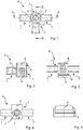
- FIG. 1 shows the base housing 8 with three connection points 1, 2, 3 and thus corresponding passage openings 1 ', 2', 3 'in the actuator receptacle 7.
- the actuator receptacle 7 is a pin 4 with four flats 5 is arranged about a central axis.
- the broken lines mark the section lines AA and BB for the cross sections in the FIGS. 2 and 3 ,
- FIG. 2 a cross section of the base housing in the direction of the BB section line.
- the pin 4 is arranged around the central axis 7.
- the connection point 2 is connected to the actuator receptacle, wherein the passage opening 2 'is formed.
- the inside of the actuator receptacle 6 has a radially circumferential recess 9, wherein the recess 9 is designed so that it has different depths.
- FIG. 3 shows a cross section of the basic housing according to FIG. 2 in the direction of in FIG. 1 marked AA cut line.
- the two connection points 1 and 3 are connected to the actuator receptacle, wherein the passage openings 1 'and 3' are formed.
- the inside of the actuator receptacle 6 has a radially circumferential recess 9, wherein the recess 9 is designed so that it has different depths.
- FIG. 4 shows a side view from the front of the main body according to the FIG. 1 ,
- the connection points 1, 2, 3 are connected to the actuator receptacle 6.
- In the middle of these compounds are the corresponding passage openings, such as the passage opening 2 'in the junction 2.
- FIG. 5 shows a part of the actuator receptacle 6 with the circumferential recess 9 on its inside.
- the recess has different depths, forming a succession of depressions and bulges.
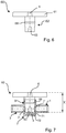
- FIG. 6 shows an embodiment of an actuator for use in connection with the basic housing according to FIG. 1 ,
- the actuator has an operating element 61 in the form of a tap with three adjusting levers, which is fixedly connected to a hollow cylindrical section 62.
- the hollow cylindrical section is arranged concentrically about a central axis 62.
- Gate-shaped passage openings 63 are formed on the operating element opposite end of the hollow cylindrical section.
- the number of passage openings 63 of the actuator corresponds to the number of connection points of the base housing.
- a radially encircling formation 69 is arranged at the hollow cylindrical portion 62 of the actuator 60 .
- FIG. 7 shows the connection of the basic housing (hatched) accordingly FIG. 1 with the actuator 60 according to the FIG. 6 as an embodiment of the multi-way valve according to the invention.
- the actuator 60 is pressed to a predetermined Einpresstiefe X in the actuator receptacle 7 of the basic housing.
- the formation 69 of the hollow cylindrical portion of the actuator 60 engages in the recess 9 on the inside of the actuator receptacle 6 of the base housing.
- the hollow cylindrical portion of the actuator 60 comprises the arranged around a central axis 6 pin 4 of the actuator exception 6 and thus forms an abutment for the actuator 60.
- the flow of the medium in the open state of the multi-way valve takes place from one of the connection points 1, 3 through the associated passage opening the basic housing 1 ', 3' through a gate-shaped passage opening of the actuator 63 via a clearance 71 between the actuator 60 and the bottom 72 of the actuator receptacle 6 to another passage opening 63 of the actuator and through the respective other passage opening 1 ', 3' of the base housing from the respective other connection point 1, 3 on the basic housing addition.
- the tightness in the upper area is achieved by a defined offset of the actuator 60 in the joining edge. Inside the base housing 8, the tightness to the corresponding passage openings 1, 2, 3 via the conical abutment, formed by the pin 4, ensured.
- the smooth running of the cock, so the easy movement of the actuator 60 in the actuator seat 7 is ensured by four flats 5 on the pin 4.
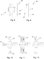
- FIGS. 8 to 12 each show a side view in FIGS. 8 and 9 and a plan view in the FIGS. 10 to 12 of differently configured reusable valves, in which in particular the controls 61 ', 61 ", 61"' are designed differently. So shows FIG. 10 a three-armed operating element 61 ', FIG. 11 a two-armed control 61 "and FIG. 12 a one-armed control, as it can be used in particular in combination with differently designed basic housings 8.
- the arrows 81 mounted on the control element further serve for easier orientation when using the reusable taps in practice in order to indicate schematically the flow direction of the fluid.
- FIGS. 13 to 15 show a further embodiment in two side views ( FIGS. 13 and 14 ) and in plan view ( Fig. 15 ).
- the essential elements are given in accordance with the above figures again.
- the embodiment shown here shows an actuator 60, wherein in the hollow cylindrical portion 62 (not shown) only two passages 82 (gates) are provided, which are in particular arranged at an angle of 90 °. According to this arrangement, depending on the circuit, the terminals 1 and 2 or 2 and 3 fluidly connected. A connection between port 3 and 1 is not possible.
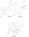
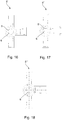
- FIGS. 16 to 18 show plan views of differently designed basic housing of the multi-way valve according to the invention, in which case in particular the central axis 6 differs in their design. So shows FIG. 16 a central axis with four flats 5, FIG. 17 a central axis 6 with three flats 5 and FIG. 18 a central axis 6 without flattening. It should be noted that in particular the embodiment according to FIG. 16 is suitable for parenteral applications and the embodiment according to FIG. 17 especially suitable for use with large hoses or larger volume throughputs.
Landscapes
- Engineering & Computer Science (AREA)
- General Engineering & Computer Science (AREA)
- Health & Medical Sciences (AREA)
- Heart & Thoracic Surgery (AREA)
- Mechanical Engineering (AREA)
- Anesthesiology (AREA)
- Hematology (AREA)
- Life Sciences & Earth Sciences (AREA)
- Animal Behavior & Ethology (AREA)
- General Health & Medical Sciences (AREA)
- Public Health (AREA)
- Veterinary Medicine (AREA)
- Biomedical Technology (AREA)
- Pulmonology (AREA)
- Infusion, Injection, And Reservoir Apparatuses (AREA)
- Multiple-Way Valves (AREA)
Description
- Die vorliegende Erfindung betrifft einen Mehrweghahn, insbesondere 2-, 3- und 4-Weghähne wie sie insbesondere in der Medizin eingesetzt werden und ein Verfahren zur Herstellung eines solchen Mehrweghahns.
- Mehrweghähne insbesondere 2-, 3- oder 4-Weghähne sind im Stand der Technik bekannt, siehe zum Beispiel
GB 1 344 166 A DE 200 05 691 U , und werden insbesondere in der Medizin und Medizintechnik eingesetzt. - Hierbei werden sie insbesondere im Infusionsbereich, dem Bereich der künstlichen Ernährung, bei der Transfusion und insbesondere für die Zu- bzw. Überleitung von verschiedenen Durchflussmedien und als sogenanntes "Injektions-Equipment" für die medizinische und pharmazeutische Ausrüstung verwendet. Die Mehrweghähne werden ferner auch in medizinischen Systemen verwendet, welche unter anderem aus mehreren Komponenten bestehen. Solche Systeme umfassen unter anderem Schwerkraftinfusionen, Pumpen oder Pumpüberleitungssysteme, Sondennahrungssysteme, Injektionen, Kombinationen hiervon und dergleichen.
- Ein Mehrweghahn kann ferner durch die Kombination mit mehreren Mehrweghähnen zu einer sog. Mehrwegehahnbank oder "Manifold" (Mehrfachverteiler) montiert werden.
- Bei der Bereitstellung von Mehrweghähnen ist von Bedeutung, dass insbesondere eine vorgegebene Dichtheit, eine leichte Bedienungsanwendung und eine Gratfreiheit der Bauteile gegeben ist. Insbesondere ist hierbei zu beachten, dass Mehrweghähne zur Zuführung unterschiedlicher Medien verwendet werden, welche unter anderem sehr unterschiedliche Viskositäten aufweisen.
- In den im Stand der Technik bekannten Mehrweghähnen ist es unter anderem von Nachteil, dass diese in verschiedenen Anwendungsfällen Schwächen aufweisen, die unter anderem die Dichtheit, die Bedienerfreundlichkeit und Probleme beim Durchfluss verschieden viskoser Medien sind.
- Darüber hinaus haben die im Stand der Technik bekannten fluiddurchströmte Mehrweghähne auch den Nachteil, dass diese unter anderem aus Kunststoffen hergestellt werden, bei deren Verarbeitung Weichmacher, wie beispielsweise Bisphenol-A eingesetzt werden. Bei der Verwendung der fluiddurchströmten Mehrweghähnen kann jedoch nicht ausgeschlossen werden, dass Teile der Weichmacher an die Flüssigkeit abgegeben werden, wobei bekannt ist, dass diese Weichmachermaterialen zu einer Belastung der körperlichen Gesundheit führen können. Unter anderem werden diesen Weichmachern Auswirkungen auf den Hormonhaushalt beziehungsweise kanzerogene Wirkungen zugeschrieben.
- Ein weiterer Nachteil der im Stand der Technik bekannten Fluidverbindungen ist, dass diese im Gebrauch zum Teil mehr oder weniger offen platziert werden, so dass diese insbesondere wenn dem Patienten keine Flüssigkeit appliziert wird, mit der Luft im Behandlungsraum bzw. sogar in Kontakt mit anderen Gegenständen und Personen gelangen und dadurch zum Beispiel mit Keimen verunreinigt werden. Diese Kontamination kann unter Umständen zu schwerwiegenden Infektionen bei den zu behandelnden Personen führen.
- Aufgabe der vorliegenden Erfindung ist es, die im Stand der Technik bekannten Nachteile wenigstens teilweise zu überwinden.
- Die vorstehende Aufgabe wird durch einen erfindungsgemäßen Mehrweghahn gemäß Anspruch 1 gelöst. Die Aufgabe wird ferner auch durch ein Verfahren zur Herstellung eines entsprechenden Mehrweghahns sowie der Verwendung eines Mehrweghahns in der Medizin und/oder Medizintechnik gelöst. Ferner wird die Aufgabe auch durch die Verwendung entsprechender Materialien für die Herstellung zumindest der mit dem Fluid in Kontakt tretenden Oberflächen gelöst. Bevorzugte Ausgestaltungsformen sowohl des Mehrweghahns, als auch des Verfahrens zur Herstellung des Mehrweghahns sind Gegenstand der entsprechenden Unteransprüche.
- Der erfindungsgemäße Mehrweghahn zum Einsatz in der Medizin und/oder Medizintechnik weist ein wenigstens abschnittsweise von einem Medium durchströmbares Grundgehäuse und ein in dem Grundgehäuse um eine zentrale Achse drehbeweglich aufgenommenes Stellglied auf. Der erfindungsgemäße Mehrweghahn ist dadurch gekennzeichnet, dass er Anschlussstellen für den Zulauf und den Ablauf des Mediums aufweist.
- Des Weiteren bildet das Grundgehäuse des erfindungsgemäßen Mehrweghahns eine Stellgliedaufnahme, welche dadurch gekennzeichnet ist, dass sie einen konzentrisch zur zentralen Achse des Grundgehäuses angeordneten Zapfen, sowie eine an der Innenseite des Grundgehäuses radial umlaufende Aussparung ausweist. Das Stellglied des erfindungsgemäßen Mehrweghahns weist ein Bedienelement, sowie einen im Wesentlichen hohlzylindrischen Abschnitt auf, der den Zapfen der Stellgliedaufnahme des Grundgehäuses wenigstens abschnittsweise aufnimmt, wenigstens eine Durchflussöffnung zur Fluidverbindung wenigstens zweier Anschlussstellen und an der Außenseite des hohlzylindrischen Abschnitts wenigstens eine radial umlaufende Ausformung aufweist.
- Der Zapfen des Grundgehäuses des erfindungsgemäßen Mehrweghahns ist so ausgebildet, dass er wenigstens im Bereich einer Anschlussstelle des Grundgehäuses ein Gegenlager für das Stellglied aufweist beziehungsweise bereitstellt, welches zusammen mit dem Stellglied eine Dichtfläche im Bereich wenigstens einer Anschlussstelle bildet. Der erfindungsgemäße Mehrweghahn ist dadurch gekennzeichnet, dass der Zapfen des Grundgehäuses wenigstens eine Abflachung am Umfang zur zentralen Achse aufweist und die Ausformung des Stellglieds in die Aussparung des Stellgliedaufnahme des Grundgehäuses zur fromschlüssigen und vorzugsweise fluiddichten Fixierung des Stellglieds in der Stellgliedaufnahme eingreift.
- Unter Medium im Sinne der vorliegenden Erfindung werden alle Arten von Fluiden, insbesondere Flüssigkeiten, wie beispielsweise wässrige Flüssigkeiten, Blut, Ernährungsbrei, etc. und auch Gase verstanden.
- Unter dem Grundgehäuse im Sinne der vorliegenden Erfindung wird ein Bauteil des Mehrweghahns, welcher das Gehäuse mit den Anschlussstellen und der Stellgliedaufnahme aufweist verstanden, wobei unter letzterer der Bereich des Grundgehäuses verstanden wird, welcher zur Aufnahme des Stellglied dient.
- Unter Stellglied im Sinne der vorliegenden Erfindung wird ein, wenigstens eine Strömungsöffnung abschließendes sogenanntes "Kücken" verstanden. Das Bedienelement im Sinne der vorliegenden Erfindung ist ein mit dem Stellglied fest verbundenes Element, wie zum Beispiel ein Hahn, mit dem sich das Stellglied um die zentrale Achse drehen lässt. Dieser kann einen oder mehrere, üblicherweise zwei, drei oder vier Stellhebel aufweisen.
- Unter einer Abflachung am Umfang des Zapfens wird eine Veränderung des kreisrunden Umfangs des Zapfens in Form einer Kreissehne in der Draufsicht verstanden, wobei die Abflachung eine entsprechende Fläche bildet.
- In einer weiteren Ausführungsform des erfindungsgemäßen Mehrweghahns, weist das Grundgehäuse zwei, drei oder vier Anschlussstellen auf.
- Gemäß einer weiteren, besonders bevorzugten Ausführungsform ist das den Mehrweghahn durchströmende Medium Flüssigkeiten, insbesondere ausgewählt aus einer Gruppe, welche Injektionslösungen, Infusionslösungen, Nährlösungen, Blut, Plasma sowie Kombinationen hieraus und dergleichen aufweist.
- Gemäß einer weiteren, besonders bevorzugten Ausführungsform weist die den Mehrweghahn durchströmende Flüssigkeit eine Viskosität auf, welche 0,7 mPa s-1 und 106 mPa s-1, bevorzugt zwischen 1 mPa s-1 und 105 mPa s-1 und besonders bevorzugt bei etwa 102 mPa s-1 liegt.
- Gemäß einer weiteren Ausführungsform des erfindungsgemäßen Mehrweghahns, ist der Zapfen des Gründgehäuses wenigstens abschnittsweise konisch ausgeführt. In einer weiteren, besonders bevorzugten Ausführungsform sind konisch und nicht konische und/oder konische Abschnitte mit verschiedenen Konuswinkel in stufiger Abfolge ausgeführt. Der Konuswinkel gemäß der vorliegenden Situation wird als Abweichung von der zentralen Achse verstanden; insbesondere werden positive und negative Winkel unter Konuswinkel verstanden. In einer weiteren, besonders bevorzugten Ausführungsform weist der Zapfen eine alternierende Folge positiver und negativer Konuswinkel auf. Im einer weiteren bevorzugten Ausführungsform weist der Zapfen relativ zur zentralen Achse nach innen oder außen versetzte, insbesondere konische Abschnitte auf.
- Gemäß einer weiteren bevorzugten Ausführungsform ist die Innenseite des hohlzylindrischen Abschnitts wenigstens abschnittsweise konisch ausgeführt und ist insbesondere an den konischen Verlauf des Zapfen im Wesentlichen angepasst.
- Gemäß der Vorliegenden Erfindung sind die Durchflussöffnungen des Stellglieds torförmig ausgeführt, insbesondere derartig ausgeführt, dass die Durchflussöffnung zum Ende des hohlzylindrischen Abschnitts des Stellglieds offen ist. Ferner wird insbesondere die Durchflussöffnung vorzugsweise in Abhängigkeit des zu verwendenden Fluids in ihrer Größe angepasst wobei ferner auch eine Kombination der Form des Gegenlagers wie beispielsweise konisch und rechteckig mit berücksichtigt wird.
- Gemäß einer weiteren, besonders bevorzugten Ausführungsform des erfindungsgemäßen Mehrweghahns entspricht die Zahl der Durchflussöffnungen des Stellglieds der Zahl der Anschlussstellen am Grundgehäuse. So weißt zum Beispiel eine Ausführungsform mit zwei Anschlussstellen zwei Durchflussöffnungen auf. Gemäß einer weiteren bevorzugten Ausführungsform weist das Stellglied weniger Durchlassöffnungen auf, als Anschlussstellen am Grundgehäuse vorhanden sind, wobei wenigstens und insbesondere zwei Durchlassöffnungen bzw. als Tore ausgestaltete Durchlassöffnungen vorgesehen sind.
- Gemäß einer weiteren, besonders bevorzugten Ausführungsform des erfindungsgemäßen Mehrweghahns weist der hohlzylindrische Abschnitt des Stellglieds zwei, drei oder vier radial zur zentralen Achse umlaufende Ausformungen auf und die Innensite der Stellgliedaufnahme weist eine entsprechende Zahl an Aussparungen auf.
- Gemäß einer weiteren, besonders bevorzugten Ausführungsform des Mehrweghahns gemäß der vorliegenden Erfindung ist die Mitte der Abflachung des Zapfens in der Stellgliedaufnahme des Grundgehäuses um 30° bis 60°, insbesondere um 45° versetzt zur Anschlussstelle des Grundgehäuses angeordnet, wobei die seitlichen Ränder der Abflachung ± 20° ± 1°, vorzugsweise ± 15 ± 2° und über etwa ± 10° von der Mitte der Abflachung versetzt angeordnet sind.
- Gemäß einer weiteren, besonders bevorzugten Ausführungsform des erfindungsgemäßen Mehrweghahns wird das Gegenlager für das Stellglied durch einen nicht abgeflachten Bereich des Zapfens gebildet. Die Modifikation der Gegenlageraufnahme durch die erfindungsgemäße eine oder mehrere Abflachungen am Zapfen führt zu einer Reduktion der Reibungsfläche zwischen Zapfen und Stellglied. Dadurch wird eine Leichtgängigkeit (Bedienerfreundlichkeit) des Mehrweghahns gewährleistet und gleichzeitig sichergestellt, dass der Hahn nicht durch das eingesetzte, insbesondere viskose Medium, aus seiner definierten, eingestellten Position verschoben werden kann.
- Unter Gegenlager im Sinne der vorliegenden Erfindung wird ein Bereich der Stellgliedaufnahme verstanden, der den Druck des auf Stellglied, insbesondere bei in geschlossenem Zustand, aufnimmt, bzw. einer Verformung des Stellglieds unter dem Druck des Mediums entgegen wirkt.
- Gemäß einer weitern, besonders bevorzugten Ausführungsform des Mehrweghahns gemäß der vorliegenden Erfindung, bilden die radial umlaufende Ausformung am hohlzylindrischen Abschnitt des Stellglieds und die Aussparung and der Innenseite der Stellgliedaufnahme eine Fügeverbindung, wobei die Fügeverbindung insbesondere einen Fügering am Gehäuse aufweist. Der Fügering weist gemäß einer weiteren bevorzugten Ausführungsform einen radial umlaufenden Dichtabschnitt und/oder einen Positionierabschnitt auf. Insbesondere ist die Fügeverbindung zwischen dem Stellglied und dem Grundgehäuse so gestaltet, dass durch die Verbindung der beiden Teile eine Dichtheit von größer als 4 bar erreicht wird.
- Gemäß einer weiteren bevorzugten Ausführungsform des erfindungsgemäßen Mehrweghahns wird wenigstens das Gehäuse und/oder das Stellglied wenigstens teilweise aus einem Material hergestellt, das aus einer Gruppe ausgewählt ist, welche neben Copolyester weitere Materialien wie zum Beispiel duro- und thermoplastische Kunststoff und insbesondere Polyphenylensulfid, Polypropylen, Poly-1-buten, Polyvinylchlorid, Polyvinylidenchlorid, Polymethyl-metaacrylat, Polyacrylnitril, Polystyrol, Polysulfon, Polyacetal, Polyvinylalkohol, Polyvinylacetat, lonomere, Fluorkunststoff, Polyethylen, Polyamid, insbesondere ein teilaromatisches Polyamid, Polycarbonat, Polyester, Copolyester, Polyphenylenoxid, Polysulfon, Polyvinylacetal, Polyurethan, und chlorierter Polyether, Zellulosenitrat, Zelluloseacetat, Zelluloseether, Phenol-Harz, Harnstoff-Harz, Thioharnstoff-Harz, Melamin-Harz, Alkylharz, Allylharz, Silicon, Polyimid, Polybenzimidazol, Epoxidharz, Casein-Kunststoff, vernetztes Polyurthan, Polyvinylchlorid, ungesättigtes Polyesterharz, antimikrobielle oder antiseptische Materialen wie beispielsweise hochporöses Silber, ionenfrei hergestelltes Silber, Silberverbindungen und insbesondere Microsilber, Metallionen freisetzende Verbindungen und Materialien, welche keine Weichmacher insbesondere kein Bisphenol A oder Phthalate enthalten, sowie Kombinationen hiervon und dergleichen umfasst.
- Gemäß einer weiteren bevorzugten Ausführungsform ist der erfindungsgemäße Mehrweghahns dadurch gekennzeichnet, dass wenigstens die mit dem Fluid in Kontakt kommenden Oberflächen des Verbindungssystems, insbesondere die innenliegenden Oberflächen des Mehrweghahns wenigstens abschnittsweise aus einem Material hergestellt sind, welches antiseptische und/oder antimikrobielle Eigenschaften aufinreist.
- Solche antimikrobielle oder antiseptsche Materialen sind beispielsweise Materialien wie hochporöses Silber, ionenfrei hergestelltes Silber, Silberverbindungen und insbesondere MicroSilber, Metallionen freisetzende Verbindungen, Kombinationen hiervon und dergleichen. Vorzugsweise werden diese im Bereich der entsprechenden Oberflächen angeordnet, wobei gemäß einer weiteren besonders bevorzugten Ausführungsform die entsprechenden Materialien auch in dem Kunststoff, aus welchem dar Mehrwegehahn bzw. dessen Bestandteile hergestellt sind eingebunden sind. So kann insbesondere ein hochporöses Silber, welches vorzugsweise auch im Wesentlichen ionenfrei hergestellt ist, in den Kunststoff eingemischt werden, wobei hieraus dann die Komponenten des Mehrweghahns wenigstens abschittsweise hergestellt werden. Alternativ liegt es auch im Sinn der vorliegenden Erfindung die Oberflächen mit einem entsprechenden Material bzw. Materialkombination zu beschichten.
- Gemäß einer weiteren besonders bevorzugten Ausführungsform der vorliegenden Erfindung wird ein amorpher Copolyester zur Herstellung des Mehrweghahns für die Medizin und Medizintechnik und dessen Verwendung insbesondere für Infussions- oder Transfussionsschläuche, Mehrwegehähne, Mehrfachverteiler, Injektionsequipment wie Nadeln, Zugänge oder ähnliches und Kombinationen hiervon verwendet. Dabei ist das System dadurch gekennzeichnet, dass wenigstens die mit dem Fluid in Kontakt kommenden Oberflächen des Verbindungssystems wenigstens abschnittsweise aus einem amorphen Copolyester hergestellt werden.
- Gemäß einer weiteren, besonders bevorzugten Ausführungsform werden wenigstens teilweise Materialien für die Herstellung des erfindungsgemäßen Verbindungssystems verwendet, welche keine Weichmacher, insbesondere keine Phthalate und kein Bisphenol A enthalten.
- Die Aufgabe der vorliegenden Erfindung wird ferner auch durch ein Verfahren zur Herstellung eines Mehrweghahns gelöst, welches wenigstens die folgenden Schritt aufweist. In einem vorzugsweise ersten Schritt der erfindungsgemäßen Verfahrens wird das Grundgehäuse sowie das Stellglied hergestellt, wobei die Herstellung vorzugsweise im Spritzgußverfahren erfolgt. Nach der Aufnahme des Grundgehäuses in eine Montagevorrichtung gemäß des erfindungsgemäßen Verfahrens, wird der hohlzylindrische Abschnitt des Stellglieds in die Stellgliedaufnahme des Grundzylinders eingeführt und eingepresst. Der Einpressvorgang wird gemäß des erfindungsgemäßen Verfahrens mit Erreichen einer vorbestimmten Einpresstiefe beendet. Die Einpresstiefe wird insbesondere durch einen definierten Anschlag bestimmt. Die Dichtheit des erfindungsgemäßen Hahns bestimmt sich insbesondere durch die Definierte Einpresstiefe. So wird die Dichtheit im oberen Bereich durch die definierte Einpresstiefe in den Fügerand erreicht. Im inneren des Gehäuses wird die Dichtheit zu den entsprechenden Durchflussöffnungen über die Einpresstiefe und damit über das konische Gegenlager sichergestellt.
- Gemäß einer weiteren, besonders bevorzugten Ausführungsform ist der die Einpresstiefe bestimmende Anschlag Bestandteil der umlaufenden Ausformung des hohlzylindrischen Abschnitts des Stellglieds und/oder Bestandteil der Stellgliedaufnahme des Grundgehäuses; insbesondere ist der Anschlag Bestandteil der Fügeverbindung.
- Gemäß einer weiteren besonders bevorzugten Ausführungsform ist der das Gegenlager bildende Zapfen wenigstens abschnittsweise hohl ausgeführt oder ist gemäß einer weiteren besonders bevorzugten Ausführungsform aus Vollmaterial hergestellt.
- Gemäß einer weiteren, besonders bevorzugten Ausführungsform handelt es sich bei den beim Fügen der Bauteile gemäß des erfindungsgemäßen Verfahrens auftretenden Verformungen im Wesentlichen um elastische Verformungen.
- Die vorliegende Erfindung umfasst ferner auch die Verwendung des erfindungsgemäßen Mehrweghahns in der Medizin und Medizintechnik, insbesondere für die Zu- und Überleitung von verschiedenen Durchflussmedien, insbesondere für die Schwerkraftinfusion, für Pumpüberleitungssysteme, Sondennahrungssysteme, Injektionen sowie Kombinationen hiervon und dergleichen.
- Die Erfindung wird nachfolgen anhand eines bevorzugten Ausführungsbeispiels erläutert, wobei darauf hingewiesen wird, dass durch dieses Beispiel Abwandlungen beziehungsweise Ergänzungen wie sie sich für den Fachmann unmittelbar ergeben mit umfasst sind. Darüber hinaus stellt dieses bevorzugte Ausführungsbeispiel keine Beschränkung der Erfindung in der Art dar, dass Abwandlungen und Ergänzungen im Umfang der vorliegenden Erfindung liegen.
- Dabei zeigen:
-
Fig. 1 eine Aufsicht auf ein Grundgehäuse eines erfindungsgemäßen Dreiweghahns; -
Fig. 2 einen Querschnitt durch das Grundgehäuse ausFig. 1 in Richtung der B-B-Schnittlinie; -
Fig. 3 einen Querschnitt durch das Grundgehäuse ausFig. 1 in Richtung der A-A-Schnittlinie; -
Fig. 4 eine Frontalansicht des Grundgehäuses ausFig. 1 ; -
Fig. 5 eine Detaildarstellung der radial umlaufenden Aussparung der Stellgliedaufnahme des Grundgehäuses; -
Fig. 6 ein Stellglied eines erfindungsgemäße Mehrweghahns; -
Fig. 7 einen Teilquerschnitt durch das Grundgehäuse ausFig. 1 in Richtung der A-A- Schnittlinie mit eingepresstem Stellglied; -
Fig. 8 bis 12 Seitenansicht und Draufsicht auf unterschiedlich ausgestaltete Mehrweghähne; -
Fig. 13 bis 15 Seitenansicht und Draufsicht auf eine besonders bevorzugte Ausführungsform eines Mehrweghahns; -
Fig. 16 bis 18 Draufsichten auf unterschiedlich ausgestaltete Grundgehäuse des erfindungsgemäßen Mehrweghahns. - Das Ausführungsbeispiel gemäß
Figur 1 zeigt das Grundgehäuse 8 mit drei Anschlussstellen 1, 2, 3 und damit korrespondierenden Durchlassöffnungen 1', 2', 3' in der Stellgliedaufnahme 7. In der Stellgliedaufnahme 7 ist um eine zentrale Achse 6 ein Zapfen 4 mit vier Abflachungen 5 angeordnet. Die Unterbrochenen Linien markieren die Schnittlinien A-A und B-B für die Querschnitte in denFiguren 2 und 3 . - So zeigt
Figur 2 einen Querschnitt des Grundgehäuses in Richtung der B-B-Schnittlinie. In der Stellgliedaufnahme 6 ist um die zentrale Achse 7 der Zapfen 4 angeordnet. Die Anschlussstelle 2 ist mit der Stellgliedaufnahme verbunden, wobei die Durchlassöffnung 2' gebildet wird. Die Innenseite der Stellgliedaufnahme 6 weist eine radial Umlaufende Aussparung 9 auf, wobei die Aussparung 9 so gestaltet ist, dass sie unterschiedliche Tiefen aufweist. -
Figur 3 zeigt einen Querschnitt des Grundgehäuses gemäßFigur 2 in Richtung der inFigur 1 markierten A-A- Schnittlinie. Die beiden Anschlussstellen 1 und 3 sind mit der Stellgliedaufnahme verbunden, wobei die Durchlassöffnungen 1' und 3' gebildet werden. Die Innenseite der Stellgliedaufnahme 6 weist eine radial Umlaufende Aussparung 9 auf, wobei die Aussparung 9 so gestaltet ist, dass sie unterschiedliche Tiefen aufweist. -
Figur 4 zeigt eine Seitenansicht von vorn des Grundgehäuses entsprechend derFigur 1 . Die Anschlussstellen 1, 2, 3 sind mit der Stellgliedaufnahme 6 verbunden. In der Mitte dieser Verbindungen befinden sich die entsprechenden Durchlassöffnungen, wie die Durchlassöffnung 2' in der Anschlussstelle 2. -
Figur 5 zeigt einen Teil der Stellgliedaufnahme 6 mit der umlaufenden Aussparung 9 an ihrer Innenseite. Die Aussparung weist verschiedene Tiefen auf, so dass eine Abfolge von Vertiefungen und Auswölbungen bildet. -
Figur 6 zeigt eine Ausführungsform eines Stellglied für die Verwendung in Verbindung mit dem Grundgehäuse gemäßFigur 1 . Das Stellglied weist ein Bedienelement 61 in Form eines Hahnes mit drei Stellhebeln auf, welches fest mit einem hohlzylindrischen Abschnitt 62 verbunden ist. Der Hohlzylindrische Abschnitt ist konzentrisch um eine zentrale Achse 62 angeordnet. An dem Bedienelement gegenüberliegendem Ende des hohlzylindrischen Abschnitts sind torförmige Durchlassöffnungen 63 ausgebildet. Die Zahl der Durchlassöffnungen 63 des Stellglieds entspricht der Zahl der Anschlussstellen des Grundgehäuses. Am hohlzylindrischen Abschnitt 62 des Stellglieds 60 ist eine radial umlaufende Ausformung 69 angeordnet. -
Figur 7 zeigt die Verbindung des Grundgehäuses (schraffiert dargestellt) entsprechendFigur 1 mit dem Stellglied 60 entsprechend derFigur 6 als eine Ausführungsform des erfindungsgemäßen Mehrweghahns. Das Stellglied 60 ist bis zu einer vorbestimmten Einpresstiefe X in die Stellgliedaufnahme 7 des Grundgehäuses eingepresst. In dieser Position greift die Ausformung 69 des hohlyzylindrischen Abschnitts des Stellglieds 60 in die Aussparung 9 an der Innenseite der Stellgliedaufnahme 6 des Grundgehäuses. Der hohlzylindrische Abschnitt des Stellglieds 60 umfasst den um eine zentrale Achse 6 angeordnete Zapfen 4 der Stellgliedausnahme 6 und bildet so ein Gegenlager für das Stellglied 60. Der Durchfluss des Mediums im geöffneten Zustand des Mehrweghahns erfolgt von einer der Anschlussstellen 1, 3 durch die zugehörige Durchlassöffnung des Grundgehäuses 1', 3' durch eine torförmige Durchlassöffnung des Stellglieds 63 über einen Freiraum 71 zwischen dem Stellglied 60 und dem Boden 72 der Stellgliedaufnahme 6 hin zur einer anderen Durchlassöffnung 63 des Stellglieds und durch die jeweils andere Durchlassöffnung 1', 3' des Grundgehäuses aus der jeweils anderes Anschlussstelle 1, 3 am Grundgehäuses hinaus. Die Dichtheit im oberen Bereich wird durch eine definierte Einpresstiefe des Stellglieds 60 in den Fügerand erreicht. Im Inneren des Grundgehäuses 8 wird die Dichtheit zu den entsprechenden Durchlassöffnungen 1, 2, 3 über das konische Gegenlager, gebildet durch den Zapfen 4, sichergestellt. Die Leichtgängigkeit des Hahns, also die leichte Beweglichkeit des Stellglieds 60 in der Stellgliedaufnahme 7 wird durch vier Abflachungen 5 am Zapfen 4 sichergestellt. - Die
Figuren 8 bis 12 zeigen je eine Seitenansicht inFigur 8 und 9 und je eine Draufsicht in denFiguren 10 bis 12 von unterschiedlich ausgestaltete Mehrweghähne, bei welchen insbesondere die Bedienelemente 61', 61", 61"' unterschiedlich ausgestaltet sind. So zeigtFigur 10 ein dreiarmiges Bedienelement 61',Figur 11 ein zweiarmiges Bedienelement 61" undFigur 12 ein einarmiges Bedienelement, wie es insbesondere in Kombination mit unterschiedlich ausgestalteten Grundgehäusen 8 verwendet werden kann. Die auf dem Bedienelement angebrachten Pfeile 81 dienen ferner der leichteren Orientierung beim Einsatz der Mehrweghähne in der Praxis, um schematisch die Flussrichtung des Fluids anzugeben. - Die
Figuren 13 bis 15 zeigen eine weitere Ausgestaltungsform in zwei Seitenansichten (Fig. 13 und 14 ) und in der Draufsicht (Fig. 15 ). Die wesentlichen Elemente sind dabei entsprechend den vorstehenden Abbildungen wieder gegeben. Darüber hinaus zeigt die hier dargestellte Ausführungsform ein Stellglied 60, bei welchem im hohlzylindrischen Abschnitt 62 (nicht dargestellt) nur zwei Durchgänge 82 (Tore) vorgesehen sind, die insbesondere zueinander mit einem Winkel von 90° angeordnet sind. Gemäß dieser Anordnung werden je nach Schaltung die Anschlüsse 1 und 2 oder 2 und 3 fluidverbunden. Eine Verbindung zwischen dem Anschluss 3 und 1 ist nicht möglich. - Die
Figuren 16 bis 18 zeigen Draufsichten auf unterschiedlich ausgestaltete Grundgehäuse des erfindungsgemäßen Mehrweghahns, wobei sich hierbei insbesondere die zentrale Achse 6 in ihrer Ausgestaltung unterscheidet. So zeigtFigur 16 eine zentrale Achse mit vier Abflachungen 5,Figur 17 eine zentrale Achse 6 mit drei Abflachungen 5 undFigur 18 eine Zentrale Achse 6 ohne Abflachungen. Dabei ist zu berücksichtigen, dass insbesondere die Ausführungsform gemäßFigur 16 für parenterale Anwendungen geeignet ist und die Ausführungsform gemäßFigur 17 insbesondere für die Verwendung mit großen Schläuchen bzw. größeren Volumendurchsätzen geeignet ist.
Claims (17)
- Mehrweghahn für den Einsatz in der Medizin oder Medizintechnik, mit wenigstens einem abschnittsweise von einem Medium durchströmbaren Grundgehäuse (8) und einem hierin, um einezentrale Achse (6) drehbeweglich aufgenommenen Stellglied (60), wobei das Grundgehäuse (8) wenigstens zwei Anschlussstellen (1, 2, 3) für den Zu- und Abfluss des Mediums aufweist und eine Stellgliedaufnahme (7) bildet, welche mit den Anschlussstellen (1,2, 3) korrespondierende Durchlassöffnungen (1', 2', 3'), einen konzentrisch zur zentralen Achse (6) angeordneten Zapfen (4) und an der Innenseite des Grundgehäuses (7) eine radial umlaufende Aussparung aufweist (9), und
das Stellglied (60) ein Bedienelement (61) und einen, im Wesentlichen hohlzylindrischen Abschnitt (62) aufweist, welcher den Zapfen (4) der Stellgliedaufnahme (7) wenigstens abschnittsweise aufnimmt, wenigstens eine Durchflussöffnung (63) zur Fluidverbindung wenigstens zweier Anschlussstellen (1,2,3) und eine, an der Außenseite des zylindrischen Abschnitts (62) wenigstens eine radial umlaufende Ausformung (69), aufweist und
dadurch gekennzeichnet, dass
der Zapfen (4) wenigstens eine Abflachung (5) am Umfang zur zentralen Achse (6) aufweist und die Ausformung (69) des Stellglieds in die Aussparung (9) der Stellgliedaufnahme (7) zur formschlüssigen und fluiddichten Fixierung des Stellglieds (60) in der Stellgliedaufnahme (7) eingreift, und die Durchflussöffnungen (63) des Stellglieds (60) als Tore ausgeführt sind, welche zum Ende des hohlzylindrischen Abschnitts (62) des Stellglieds offen sind,
der Zapfen (4) sich vom Boden (72) der Stellgliedaufnahme über die Durchlassöffnungen (1', 2', 3') des Grundgehäuses erstreckt und ein Gegenlager für das Stellglied (60) bildet, um die Dichtheit zu den Durchlassöffnungen (1', 2', 3') sicherzustellen. - Mehrweghahn gemäß Anspruch 1, dadurch gekennzeichnet, dass das Grundgehäuse (8) zwei, drei oder vier Anschlussstellen (1, 2, 3) aufweist.
- Mehrwegehahn gemäß einem der vorstehenden Ansprüche, dadurch gekennzeichnet, dass
das Medium eine Flüssigkeit ist, die aus einer Gruppe ausgewählt wird, welche Injektionslösungen, Infusionslösungen, Nährlösungen, Blut, Plasma, Gasesowie Kombinationen hieraus aufweist. - Mehrweghahn gemäß Anspruch 3, dadurch gekennzeichnet, dass
die Flüssigkeit eine Viskosität aufweist, welche zwischen 0,7 mPa s-1 und 106 mPa s-1, insbesondere zwischen 1 mPa s-1 und 105 mPa s-1, und besonders bevorzugt bei etwa 102 mPa s-1 liegt. - Mehrweghahn gemäß einem der vorstehenden Ansprüche, dadurch gekennzeichnet, dass
der Zapfen (4) wenigstens abschnittsweise konisch, vorzugsweise in stufiger Abfolge und/oder mit unterschiedlichen Konuswinkeln ausgeführt ist, - Mehrwegehahn gemäß einem der vorstehenden Ansprüche, dadurch gekennzeichnet, dass
die Innenseite des zylindrischen Abschnitts (62) des Stellglieds (60) wenigstens abschnittsweise konisch ausgeführt ist und insbesondere dem konischen Verlauf des Zapfens (4) im Wesentlichen entspricht. - Mehrweghahn gemäß einem der vorstehenden Ansprüche, dadurch gekennzeichnet, dass
die Zahl der Durchflussöffnungen (63) des Stellglieds (60) der Zahl der Anschlussstellen (1, 2, 3) im Grundgehäuse (8) entspricht. - Mehrwegehahn gemäß einem der vorstehenden Ansprüche, dadurch gekennzeichnet, dass zwei, drei oder vier radial zur zentralen Achse umlaufende Ausformung (69) im hohlzylindrischen Abschnitt (62) des Stellglieds (60) und eine entsprechende Zahl an Aussparungen (9) in der Stellgliedaufnahme (7) vorgesehen sind.
- Mehrweghahn gemäß einem der vorstehenden Ansprüche, dadurch gekennzeichnet, dass
die Mitte der Abflachung (5) am Zapfen (4) um 30° bis 60° und insbesondere um etwa 45° versetzt zur Anschlussstelle angeordnet ist, und die Ränder der Ablachung ± 20° ± 1°, vorzugsweise ± 15 ± 2° und über etwa ± 10° von der Mitte der Abflachung (5) versetzt angeordnet sind. - Mehrweghahn gemäß einem der vorstehenden Ansprüche, dadurch gekennzeichnet, dass
das Gegenlager für das Stellglied (60) durch einen nicht abgeflachten Bereich des Zapfens (4) gebildet wird. - Mehrweghahn gemäß einem der vorstehenden Ansprüche, dadurch gekennzeichnet, dass
die umlaufende Ausformung (69) im hohlzylindrischen Abschnitt (62) des Stellglieds (60) und die Aussparung (9) in der Stellgliedaufnahme (7) eine Fügeverbindung bilden, welche insbesondere einen Fügering am Gehäuse aufweist. - Mehrweghahn gemäß Anspruch 12, dadurch gekennzeichnet, dass
der Fügering einen radial umlaufenden Dichtabschnitt und/oder Positionierabschnitt aufweist. - Mehrweghahn gemäß einem der vorstehenden Ansprüche, dadurch gekennzeichnet, dass das wenigstens das Grundgehäuse (8) und/oder das Stellglied (60) wenigstens teilweise aus einem Material hergestellt sind, das aus einer Gruppe ausgewählt ist, welche neben Copolyester, insbesodere amorphe Copolyester, weitere Materialien wie zum Beispiel duro- und thermoplastische Kunststoff und insbesondere Polyphenylensulfid, Polypropylen, Poly-1-buten, Polyvinylchlorid, Polyvinylidenchlorid, Polymethyl-metaacrylat, Polyacrylnitril, Polystyrol, Polysulfon, Polyacetal, Polyvinylalkohol, Polyvinylacetat, Ionomere, Fluorkunststoff, Polyethylen, Polyamid, insbesondere ein teilaromatisches Polyamid, Polycarbonat, Polyester, Copolyester, Polyphenylenoxid, Polysulfon, Polyvinylacetal, Polyurethan, und chlorierter Polyether, Zellulosenitrat, Zelluloseacetat, Zelluloseether, Phenol-Harz, Harnstoff-Harz, Thioharnstoff-Harz, Melamin-Harz, Alkylharz, Allylharz, Silicon, Polyimid, Polybenzimidazol, Epoxidharz, Casein-Kunststoff, vernetztes Polyurthan, Polyvinylchlorid, ungesättigtes Polyesterharz, antimikrobielle oder antiseptische Materialen wie beispielsweise hochporöses Silber, ionenfrei hergestelltes Silber, Silberverbindungen und insbesondere Microsilber, Metallionen freisetzende Verbindungen und Materialien, welche keine Weichmacher, insbesondere kein Bisphenol A oder Phthalate enthalten, sowie Kombinationen hiervon umfasst.
- Verfahren zur Herstellung eines Mehrweghahns gemäß einem der vorstehenden Ansprüche mit den Schritten- Herstellen des Grundgehäuses (8) und des Stellglieds (60) vorzugsweise im Spritzgussverfahren;- Aufnahme des Grundgehäuses (8) und des Stellglieds (60) in eine Montagevorrichtung;- Einführen und Einpressen des hohlzylindrischen Abschnitts (62) des Stellglieds (60) in die Stellgliedaufnahme (7);- Beenden des Einpressvorgang mit Erreichen einer vorbestimmten Einpresstiefe (X), die insbesondere durch einen definierten Anschlag bestimmt wird.
- Verfahren gemäß Anspruch 14 dadurch gekennzeichnet, dass der Anschlag Bestandteil der umlaufenden Ausformung (69) im hohlzylindrischen Abschnitt (62) des Stellglieds (60) und/oder der Aussparung (9) in der Stellgliedaufnahme (7) und insbesondere der Fügeverbindung ist.
- Verfahren gemäß einem der Ansprüche 14 oder 15 dadurch gekennzeichnet, dass
die Verformungen beim Fügen der Bauteile, insbesondere im Bereich der Fügeverbindung im Wesentlichen elastische Verformungen sind. - Verwendung eines Mehrweghahns gemäß einem der Ansprüche 1 bis 13 in der Medizin und/oder Medizintechnik, für die Zu- bzw. Überleitung von verschiedenen Durchflussmedien für die Schwerkraftinfusion, Pumpüberleitungssysteme, Sondennahrungssysteme, und/oder Injektionen.
Priority Applications (2)
| Application Number | Priority Date | Filing Date | Title |
|---|---|---|---|
| EP17161951.3A EP3225890B1 (de) | 2009-07-14 | 2010-07-14 | Mehrweghahn und verfahren zu dessen herstellung |
| DK17161951.3T DK3225890T3 (da) | 2009-07-14 | 2010-07-14 | Flervejsventil og produktionsmetode for samme |
Applications Claiming Priority (2)
| Application Number | Priority Date | Filing Date | Title |
|---|---|---|---|
| DE102009026172A DE102009026172A1 (de) | 2009-07-14 | 2009-07-14 | Mehrweghahn und Verfahren zu dessen Herstellung |
| PCT/EP2010/060150 WO2011006934A1 (de) | 2009-07-14 | 2010-07-14 | Mehrweghahn und verfahren zu dessen herstellung |
Related Child Applications (1)
| Application Number | Title | Priority Date | Filing Date |
|---|---|---|---|
| EP17161951.3A Division EP3225890B1 (de) | 2009-07-14 | 2010-07-14 | Mehrweghahn und verfahren zu dessen herstellung |
Publications (2)
| Publication Number | Publication Date |
|---|---|
| EP2454506A1 EP2454506A1 (de) | 2012-05-23 |
| EP2454506B1 true EP2454506B1 (de) | 2017-03-29 |
Family
ID=43016869
Family Applications (2)
| Application Number | Title | Priority Date | Filing Date |
|---|---|---|---|
| EP10742107.5A Active EP2454506B1 (de) | 2009-07-14 | 2010-07-14 | Mehrweghahn und verfahren zu dessen herstellung |
| EP17161951.3A Active EP3225890B1 (de) | 2009-07-14 | 2010-07-14 | Mehrweghahn und verfahren zu dessen herstellung |
Family Applications After (1)
| Application Number | Title | Priority Date | Filing Date |
|---|---|---|---|
| EP17161951.3A Active EP3225890B1 (de) | 2009-07-14 | 2010-07-14 | Mehrweghahn und verfahren zu dessen herstellung |
Country Status (8)
| Country | Link |
|---|---|
| US (1) | US8695624B2 (de) |
| EP (2) | EP2454506B1 (de) |
| CN (1) | CN102472401B (de) |
| CA (1) | CA2767871C (de) |
| DE (1) | DE102009026172A1 (de) |
| DK (2) | DK2454506T3 (de) |
| ES (2) | ES2629834T3 (de) |
| WO (1) | WO2011006934A1 (de) |
Families Citing this family (23)
| Publication number | Priority date | Publication date | Assignee | Title |
|---|---|---|---|---|
| DE102009026172A1 (de) | 2009-07-14 | 2011-01-27 | Hans Jürgen Hopf Betriebsgesellschaft | Mehrweghahn und Verfahren zu dessen Herstellung |
| US9375561B2 (en) * | 2011-09-02 | 2016-06-28 | Carefusion 303, Inc. | Self-flushing valve |
| US9695323B2 (en) | 2013-02-13 | 2017-07-04 | Becton, Dickinson And Company | UV curable solventless antimicrobial compositions |
| US9750928B2 (en) | 2013-02-13 | 2017-09-05 | Becton, Dickinson And Company | Blood control IV catheter with stationary septum activator |
| US10792398B2 (en) | 2014-02-20 | 2020-10-06 | Becton, Dickinson And Company | Antimicrobial inserts for medical devices |
| US10792399B2 (en) | 2014-02-20 | 2020-10-06 | Becton, Dickinson And Company | Antimicrobial inserts for medical devices |
| US9675793B2 (en) | 2014-04-23 | 2017-06-13 | Becton, Dickinson And Company | Catheter tubing with extraluminal antimicrobial coating |
| US10376686B2 (en) | 2014-04-23 | 2019-08-13 | Becton, Dickinson And Company | Antimicrobial caps for medical connectors |
| US9789279B2 (en) | 2014-04-23 | 2017-10-17 | Becton, Dickinson And Company | Antimicrobial obturator for use with vascular access devices |
| US10149971B2 (en) * | 2014-04-23 | 2018-12-11 | Becton, Dickinson And Company | Antimicrobial stopcock medical connector |
| US10232088B2 (en) | 2014-07-08 | 2019-03-19 | Becton, Dickinson And Company | Antimicrobial coating forming kink resistant feature on a vascular access device |
| EP3048345A1 (de) * | 2015-01-21 | 2016-07-27 | Anheuser-Busch InBev S.A. | Absperrhahn für Getränkespender |
| US10004890B2 (en) | 2015-01-27 | 2018-06-26 | Becton, Dickinson And Company | Antimicrobial inserts for stopcock medical connectors |
| US10953215B2 (en) * | 2015-04-08 | 2021-03-23 | Dale Medical Products, Inc. | Non-luer compatible administration port |
| US10493244B2 (en) | 2015-10-28 | 2019-12-03 | Becton, Dickinson And Company | Extension tubing strain relief |
| US9765899B2 (en) * | 2015-11-03 | 2017-09-19 | Stoma Ventures, LLC | Disposable dental valve device |
| DE102015119899A1 (de) * | 2015-11-17 | 2017-05-18 | Hans-Jürgen Hopf | Mehrweghahn mit Mehrfachhaltering |
| US9914190B2 (en) * | 2016-06-07 | 2018-03-13 | Robert G. Hartness | Blast gate for vacuum system |
| JP6104443B1 (ja) | 2016-08-26 | 2017-03-29 | 伸和コントロールズ株式会社 | 流量制御用三方弁及びこれを用いた温度制御装置 |
| DE102017129033A1 (de) * | 2017-12-06 | 2019-06-06 | Hans-Jürgen Hopf | Kükenhahn für die Medizintechnik |
| DE102019126775A1 (de) * | 2019-10-04 | 2021-04-08 | Eto Magnetic Gmbh | Drehschieberventil zur Regelung eines Fluidflusses sowie Verfahren zur Herstellung eines Drehschieberventils |
| CN114555923B (zh) * | 2019-10-11 | 2024-03-12 | 索格菲空气冷却公司 | 用于多个中空主体或外壳之间的流体循环的系统 |
| EP3967742A1 (de) | 2020-09-15 | 2022-03-16 | WeylChem Performance Products GmbH | Bleichkatalysatorhaltige zusammensetzungen, verfahren zu ihrer herstellung und bleich- und reinigungsmittel damit |
Citations (12)
| Publication number | Priority date | Publication date | Assignee | Title |
|---|---|---|---|---|
| US3185179A (en) | 1961-05-05 | 1965-05-25 | Pharmaseal Lab | Disposable valve |
| US3750704A (en) | 1971-10-08 | 1973-08-07 | Burron Medical Prod Inc | Multi-way valve |
| US3783900A (en) | 1972-06-05 | 1974-01-08 | Medex Inc | Stop cock |
| GB1344166A (en) | 1971-01-27 | 1974-01-16 | Dameco Medical Products Ab | Infusion cannula apparatus |
| JPS5318940A (en) | 1976-08-05 | 1978-02-21 | Nippon Telegr & Teleph Corp <Ntt> | Contact selection deiving unit for ocean block equalizer |
| US5074334A (en) | 1989-07-27 | 1991-12-24 | Terumo Kabushiki Kaisha | Multi-way cock |
| US5522430A (en) | 1994-11-15 | 1996-06-04 | Mittersteiner Urzua; Melchor J. | Flow valve or shut-off cock for flow networks with sealing means |
| JP2002153562A (ja) | 2000-11-22 | 2002-05-28 | Jms Co Ltd | 三方活栓 |
| EP1234596A1 (de) | 1999-11-29 | 2002-08-28 | Nippon Sherwood Medical Industries Ltd. | Medizinischer hahn |
| US6536742B2 (en) | 2000-03-28 | 2003-03-25 | B. Braun Melsungen Ag | Multi-way cock |
| US20070191760A1 (en) | 2005-11-28 | 2007-08-16 | Nippon Sherwood Medical Industries, Ltd. | Stopcock for Medical Treatment |
| WO2011006934A1 (de) | 2009-07-14 | 2011-01-20 | Hans Jürgen Hopf Besitzgesellschaft | Mehrweghahn und verfahren zu dessen herstellung |
Family Cites Families (11)
| Publication number | Priority date | Publication date | Assignee | Title |
|---|---|---|---|---|
| US3481367A (en) * | 1967-06-13 | 1969-12-02 | Brunswick Corp | Three-way stopcock |
| GB1357424A (en) | 1970-07-09 | 1974-06-19 | Lauxiliaire De Lindustrie Et D | Valves |
| DE3503044A1 (de) | 1985-01-30 | 1986-07-31 | Hans-Dieter 7524 Östringen Bender | Einrichtung zum verabreichen von infusionen, transfusionen oder injektionen sowie zur aspiration von blut |
| US5207641A (en) | 1989-05-15 | 1993-05-04 | Bird Medical International Inc. | Medical rotary valve having aspiration, insufflation and an intermediate flushing positions |
| GB9521120D0 (en) * | 1995-10-16 | 1995-12-20 | Boc Group Plc | Improvements in stopcocks |
| US6880808B2 (en) | 2002-05-03 | 2005-04-19 | Acist Medical Systems, Inc. | Gamma-stable high pressure stopcock |
| FR2845452B1 (fr) | 2002-10-04 | 2005-09-23 | Vygon | Robinet a cle tournante indexable. |
| CN2666473Y (zh) * | 2003-12-19 | 2004-12-29 | 中山大学中山眼科中心 | 一种眼内灌注系统的卡口式三通管阀 |
| CN2928125Y (zh) * | 2006-06-22 | 2007-08-01 | 韩东 | 三位三通换向阀 |
| DE202007014342U1 (de) * | 2007-10-12 | 2008-01-03 | Fresenius Kabi Deutschland Gmbh | Vorrichtung zum Zuführen von medizinischen Flüssigkeiten |
| DE202010004098U1 (de) * | 2010-03-23 | 2011-08-10 | N.V. Nutricia | Mehrwegehahn |
-
2009
- 2009-07-14 DE DE102009026172A patent/DE102009026172A1/de not_active Ceased
-
2010
- 2010-07-14 US US13/383,754 patent/US8695624B2/en active Active
- 2010-07-14 ES ES10742107.5T patent/ES2629834T3/es active Active
- 2010-07-14 DK DK10742107.5T patent/DK2454506T3/en active
- 2010-07-14 ES ES17161951T patent/ES2843000T3/es active Active
- 2010-07-14 DK DK17161951.3T patent/DK3225890T3/da active
- 2010-07-14 CA CA2767871A patent/CA2767871C/en active Active
- 2010-07-14 EP EP10742107.5A patent/EP2454506B1/de active Active
- 2010-07-14 CN CN201080031955.3A patent/CN102472401B/zh active Active
- 2010-07-14 EP EP17161951.3A patent/EP3225890B1/de active Active
- 2010-07-14 WO PCT/EP2010/060150 patent/WO2011006934A1/de not_active Ceased
Patent Citations (12)
| Publication number | Priority date | Publication date | Assignee | Title |
|---|---|---|---|---|
| US3185179A (en) | 1961-05-05 | 1965-05-25 | Pharmaseal Lab | Disposable valve |
| GB1344166A (en) | 1971-01-27 | 1974-01-16 | Dameco Medical Products Ab | Infusion cannula apparatus |
| US3750704A (en) | 1971-10-08 | 1973-08-07 | Burron Medical Prod Inc | Multi-way valve |
| US3783900A (en) | 1972-06-05 | 1974-01-08 | Medex Inc | Stop cock |
| JPS5318940A (en) | 1976-08-05 | 1978-02-21 | Nippon Telegr & Teleph Corp <Ntt> | Contact selection deiving unit for ocean block equalizer |
| US5074334A (en) | 1989-07-27 | 1991-12-24 | Terumo Kabushiki Kaisha | Multi-way cock |
| US5522430A (en) | 1994-11-15 | 1996-06-04 | Mittersteiner Urzua; Melchor J. | Flow valve or shut-off cock for flow networks with sealing means |
| EP1234596A1 (de) | 1999-11-29 | 2002-08-28 | Nippon Sherwood Medical Industries Ltd. | Medizinischer hahn |
| US6536742B2 (en) | 2000-03-28 | 2003-03-25 | B. Braun Melsungen Ag | Multi-way cock |
| JP2002153562A (ja) | 2000-11-22 | 2002-05-28 | Jms Co Ltd | 三方活栓 |
| US20070191760A1 (en) | 2005-11-28 | 2007-08-16 | Nippon Sherwood Medical Industries, Ltd. | Stopcock for Medical Treatment |
| WO2011006934A1 (de) | 2009-07-14 | 2011-01-20 | Hans Jürgen Hopf Besitzgesellschaft | Mehrweghahn und verfahren zu dessen herstellung |
Also Published As
| Publication number | Publication date |
|---|---|
| ES2629834T3 (es) | 2017-08-16 |
| CA2767871A1 (en) | 2011-01-20 |
| DE102009026172A1 (de) | 2011-01-27 |
| DK2454506T3 (en) | 2017-07-17 |
| EP2454506A1 (de) | 2012-05-23 |
| EP3225890A1 (de) | 2017-10-04 |
| DK3225890T3 (da) | 2021-02-22 |
| CA2767871C (en) | 2017-07-18 |
| CN102472401B (zh) | 2014-08-13 |
| EP3225890B1 (de) | 2020-12-30 |
| WO2011006934A1 (de) | 2011-01-20 |
| CN102472401A (zh) | 2012-05-23 |
| ES2843000T3 (es) | 2021-07-15 |
| US20120103448A1 (en) | 2012-05-03 |
| US8695624B2 (en) | 2014-04-15 |
Similar Documents
| Publication | Publication Date | Title |
|---|---|---|
| EP2454506B1 (de) | Mehrweghahn und verfahren zu dessen herstellung | |
| EP2490753B1 (de) | Mehrwegehahn mit antiseptisch bzw. antimikrobiell wirkenden oberflächen | |
| EP3377167B1 (de) | Mehrweghahn mit mehrfachhaltering | |
| EP2421579B1 (de) | Ventilvorrichtung, ventileinsatz, externe funktionseinrichtung, behandlungsvorrichtung sowie verfahren | |
| EP2459270A2 (de) | Anschlusssystem für fluidverbindungen in der medizin | |
| DE112014001032T5 (de) | Umschaltventilvorrichtung | |
| EP0210432A1 (de) | Durchflussregelvorrichtung | |
| WO2017140849A1 (de) | Ventileinheit für eine anlage zur herstellung einer medizinischen zubereitung | |
| EP2525865B1 (de) | Fluiddurchströmte verbindungssysteme zum einsatz in der medizin und medizintechnik | |
| DE4325837C2 (de) | Sicherheitsverbinder für die Infusionstherapie | |
| EP0638328A1 (de) | Rückschlagventil | |
| WO1989002764A1 (fr) | Agencement de clapet antiretour | |
| EP2885035B1 (de) | Einweg-ventileinrichtung | |
| WO2016206804A1 (de) | Adapter | |
| DE20216791U1 (de) | Luftabscheider | |
| EP2195075B1 (de) | Vorrichtung zum zuführen von medizinischen flüssigkeiten | |
| EP2379161B1 (de) | Vorrichtung zum zuführen von medizinischen flüssigkeiten | |
| WO2006012769A1 (de) | Präzisions-dosimeter | |
| EP3416890B1 (de) | Ventileinheit für eine anlage zur herstellung einer medizinischen zubereitung | |
| DE202007014342U1 (de) | Vorrichtung zum Zuführen von medizinischen Flüssigkeiten | |
| EP2827939A1 (de) | Einwegeventil für ein infusionsbesteck | |
| DD251296A1 (de) | Hahn fuer dosiergeraete |
Legal Events
| Date | Code | Title | Description |
|---|---|---|---|
| PUAI | Public reference made under article 153(3) epc to a published international application that has entered the european phase |
Free format text: ORIGINAL CODE: 0009012 |
|
| 17P | Request for examination filed |
Effective date: 20120214 |
|
| AK | Designated contracting states |
Kind code of ref document: A1 Designated state(s): AL AT BE BG CH CY CZ DE DK EE ES FI FR GB GR HR HU IE IS IT LI LT LU LV MC MK MT NL NO PL PT RO SE SI SK SM TR |
|
| DAX | Request for extension of the european patent (deleted) | ||
| REG | Reference to a national code |
Ref country code: DE Ref legal event code: R079 Ref document number: 502010013385 Country of ref document: DE Free format text: PREVIOUS MAIN CLASS: F16K0011085000 Ipc: A61M0039220000 |
|
| GRAP | Despatch of communication of intention to grant a patent |
Free format text: ORIGINAL CODE: EPIDOSNIGR1 |
|
| RIC1 | Information provided on ipc code assigned before grant |
Ipc: A61M 39/16 20060101ALI20160914BHEP Ipc: F16K 27/06 20060101ALI20160914BHEP Ipc: F16K 11/085 20060101ALI20160914BHEP Ipc: A61M 39/22 20060101AFI20160914BHEP |
|
| INTG | Intention to grant announced |
Effective date: 20161019 |
|
| GRAS | Grant fee paid |
Free format text: ORIGINAL CODE: EPIDOSNIGR3 |
|
| STAA | Information on the status of an ep patent application or granted ep patent |
Free format text: STATUS: GRANT OF PATENT IS INTENDED |
|
| GRAA | (expected) grant |
Free format text: ORIGINAL CODE: 0009210 |
|
| STAA | Information on the status of an ep patent application or granted ep patent |
Free format text: STATUS: THE PATENT HAS BEEN GRANTED |
|
| RAP1 | Party data changed (applicant data changed or rights of an application transferred) |
Owner name: FRESENIUS KABI DEUTSCHLAND GMBH |
|
| AK | Designated contracting states |
Kind code of ref document: B1 Designated state(s): AL AT BE BG CH CY CZ DE DK EE ES FI FR GB GR HR HU IE IS IT LI LT LU LV MC MK MT NL NO PL PT RO SE SI SK SM TR |
|
| REG | Reference to a national code |
Ref country code: GB Ref legal event code: FG4D Free format text: NOT ENGLISH |
|
| REG | Reference to a national code |
Ref country code: CH Ref legal event code: EP |
|
| REG | Reference to a national code |
Ref country code: AT Ref legal event code: REF Ref document number: 879173 Country of ref document: AT Kind code of ref document: T Effective date: 20170415 |
|
| REG | Reference to a national code |
Ref country code: IE Ref legal event code: FG4D Free format text: LANGUAGE OF EP DOCUMENT: GERMAN |
|
| REG | Reference to a national code |
Ref country code: DE Ref legal event code: R096 Ref document number: 502010013385 Country of ref document: DE |
|
| REG | Reference to a national code |
Ref country code: CH Ref legal event code: NV Representative=s name: COSMOVICI INTELLECTUAL PROPERTY SARL, CH |
|
| REG | Reference to a national code |
Ref country code: NL Ref legal event code: FP |
|
| REG | Reference to a national code |
Ref country code: DK Ref legal event code: T3 Effective date: 20170706 |
|
| REG | Reference to a national code |
Ref country code: SE Ref legal event code: TRGR |
|
| REG | Reference to a national code |
Ref country code: FR Ref legal event code: PLFP Year of fee payment: 8 |
|
| PG25 | Lapsed in a contracting state [announced via postgrant information from national office to epo] |
Ref country code: FI Free format text: LAPSE BECAUSE OF FAILURE TO SUBMIT A TRANSLATION OF THE DESCRIPTION OR TO PAY THE FEE WITHIN THE PRESCRIBED TIME-LIMIT Effective date: 20170329 Ref country code: HR Free format text: LAPSE BECAUSE OF FAILURE TO SUBMIT A TRANSLATION OF THE DESCRIPTION OR TO PAY THE FEE WITHIN THE PRESCRIBED TIME-LIMIT Effective date: 20170329 Ref country code: GR Free format text: LAPSE BECAUSE OF FAILURE TO SUBMIT A TRANSLATION OF THE DESCRIPTION OR TO PAY THE FEE WITHIN THE PRESCRIBED TIME-LIMIT Effective date: 20170630 Ref country code: LT Free format text: LAPSE BECAUSE OF FAILURE TO SUBMIT A TRANSLATION OF THE DESCRIPTION OR TO PAY THE FEE WITHIN THE PRESCRIBED TIME-LIMIT Effective date: 20170329 |
|
| REG | Reference to a national code |
Ref country code: ES Ref legal event code: FG2A Ref document number: 2629834 Country of ref document: ES Kind code of ref document: T3 Effective date: 20170816 |
|
| PG25 | Lapsed in a contracting state [announced via postgrant information from national office to epo] |
Ref country code: LV Free format text: LAPSE BECAUSE OF FAILURE TO SUBMIT A TRANSLATION OF THE DESCRIPTION OR TO PAY THE FEE WITHIN THE PRESCRIBED TIME-LIMIT Effective date: 20170329 Ref country code: BG Free format text: LAPSE BECAUSE OF FAILURE TO SUBMIT A TRANSLATION OF THE DESCRIPTION OR TO PAY THE FEE WITHIN THE PRESCRIBED TIME-LIMIT Effective date: 20170629 |
|
| REG | Reference to a national code |
Ref country code: NO Ref legal event code: T2 Effective date: 20170329 |
|
| PG25 | Lapsed in a contracting state [announced via postgrant information from national office to epo] |
Ref country code: RO Free format text: LAPSE BECAUSE OF FAILURE TO SUBMIT A TRANSLATION OF THE DESCRIPTION OR TO PAY THE FEE WITHIN THE PRESCRIBED TIME-LIMIT Effective date: 20170329 Ref country code: SK Free format text: LAPSE BECAUSE OF FAILURE TO SUBMIT A TRANSLATION OF THE DESCRIPTION OR TO PAY THE FEE WITHIN THE PRESCRIBED TIME-LIMIT Effective date: 20170329 Ref country code: EE Free format text: LAPSE BECAUSE OF FAILURE TO SUBMIT A TRANSLATION OF THE DESCRIPTION OR TO PAY THE FEE WITHIN THE PRESCRIBED TIME-LIMIT Effective date: 20170329 Ref country code: CZ Free format text: LAPSE BECAUSE OF FAILURE TO SUBMIT A TRANSLATION OF THE DESCRIPTION OR TO PAY THE FEE WITHIN THE PRESCRIBED TIME-LIMIT Effective date: 20170329 |
|
| PG25 | Lapsed in a contracting state [announced via postgrant information from national office to epo] |
Ref country code: SM Free format text: LAPSE BECAUSE OF FAILURE TO SUBMIT A TRANSLATION OF THE DESCRIPTION OR TO PAY THE FEE WITHIN THE PRESCRIBED TIME-LIMIT Effective date: 20170329 Ref country code: PL Free format text: LAPSE BECAUSE OF FAILURE TO SUBMIT A TRANSLATION OF THE DESCRIPTION OR TO PAY THE FEE WITHIN THE PRESCRIBED TIME-LIMIT Effective date: 20170329 Ref country code: PT Free format text: LAPSE BECAUSE OF FAILURE TO SUBMIT A TRANSLATION OF THE DESCRIPTION OR TO PAY THE FEE WITHIN THE PRESCRIBED TIME-LIMIT Effective date: 20170731 Ref country code: IS Free format text: LAPSE BECAUSE OF FAILURE TO SUBMIT A TRANSLATION OF THE DESCRIPTION OR TO PAY THE FEE WITHIN THE PRESCRIBED TIME-LIMIT Effective date: 20170729 |
|
| REG | Reference to a national code |
Ref country code: DE Ref legal event code: R026 Ref document number: 502010013385 Country of ref document: DE |
|
| PLBI | Opposition filed |
Free format text: ORIGINAL CODE: 0009260 |
|
| PLAB | Opposition data, opponent's data or that of the opponent's representative modified |
Free format text: ORIGINAL CODE: 0009299OPPO |
|
| REG | Reference to a national code |
Ref country code: CH Ref legal event code: PCAR Free format text: NEW ADDRESS: 14 RUE DU RHONE, 1204 GENEVE (CH) |
|
| 26 | Opposition filed |
Opponent name: N.V. NUTRICIA Effective date: 20171220 |
|
| R26 | Opposition filed (corrected) |
Opponent name: N.V. NUTRICIA Effective date: 20171220 |
|
| PLAX | Notice of opposition and request to file observation + time limit sent |
Free format text: ORIGINAL CODE: EPIDOSNOBS2 |
|
| REG | Reference to a national code |
Ref country code: IE Ref legal event code: MM4A |
|
| PG25 | Lapsed in a contracting state [announced via postgrant information from national office to epo] |
Ref country code: IE Free format text: LAPSE BECAUSE OF NON-PAYMENT OF DUE FEES Effective date: 20170714 |
|
| PG25 | Lapsed in a contracting state [announced via postgrant information from national office to epo] |
Ref country code: SI Free format text: LAPSE BECAUSE OF FAILURE TO SUBMIT A TRANSLATION OF THE DESCRIPTION OR TO PAY THE FEE WITHIN THE PRESCRIBED TIME-LIMIT Effective date: 20170329 |
|
| PG25 | Lapsed in a contracting state [announced via postgrant information from national office to epo] |
Ref country code: LU Free format text: LAPSE BECAUSE OF NON-PAYMENT OF DUE FEES Effective date: 20170714 |
|
| PLBB | Reply of patent proprietor to notice(s) of opposition received |
Free format text: ORIGINAL CODE: EPIDOSNOBS3 |
|
| REG | Reference to a national code |
Ref country code: FR Ref legal event code: PLFP Year of fee payment: 9 |
|
| PG25 | Lapsed in a contracting state [announced via postgrant information from national office to epo] |
Ref country code: MT Free format text: LAPSE BECAUSE OF FAILURE TO SUBMIT A TRANSLATION OF THE DESCRIPTION OR TO PAY THE FEE WITHIN THE PRESCRIBED TIME-LIMIT Effective date: 20170329 |
|
| PLAB | Opposition data, opponent's data or that of the opponent's representative modified |
Free format text: ORIGINAL CODE: 0009299OPPO |
|
| R26 | Opposition filed (corrected) |
Opponent name: N.V. NUTRICIA Effective date: 20171220 |
|
| PG25 | Lapsed in a contracting state [announced via postgrant information from national office to epo] |
Ref country code: MC Free format text: LAPSE BECAUSE OF FAILURE TO SUBMIT A TRANSLATION OF THE DESCRIPTION OR TO PAY THE FEE WITHIN THE PRESCRIBED TIME-LIMIT Effective date: 20170329 Ref country code: HU Free format text: LAPSE BECAUSE OF FAILURE TO SUBMIT A TRANSLATION OF THE DESCRIPTION OR TO PAY THE FEE WITHIN THE PRESCRIBED TIME-LIMIT; INVALID AB INITIO Effective date: 20100714 |
|
| PLAB | Opposition data, opponent's data or that of the opponent's representative modified |
Free format text: ORIGINAL CODE: 0009299OPPO |
|
| R26 | Opposition filed (corrected) |
Opponent name: N.V. NUTRICIA Effective date: 20171220 |
|
| PG25 | Lapsed in a contracting state [announced via postgrant information from national office to epo] |
Ref country code: CY Free format text: LAPSE BECAUSE OF NON-PAYMENT OF DUE FEES Effective date: 20170329 |
|
| PG25 | Lapsed in a contracting state [announced via postgrant information from national office to epo] |
Ref country code: MK Free format text: LAPSE BECAUSE OF FAILURE TO SUBMIT A TRANSLATION OF THE DESCRIPTION OR TO PAY THE FEE WITHIN THE PRESCRIBED TIME-LIMIT Effective date: 20170329 |
|
| APBM | Appeal reference recorded |
Free format text: ORIGINAL CODE: EPIDOSNREFNO |
|
| APBP | Date of receipt of notice of appeal recorded |
Free format text: ORIGINAL CODE: EPIDOSNNOA2O |
|
| APAH | Appeal reference modified |
Free format text: ORIGINAL CODE: EPIDOSCREFNO |
|
| APBM | Appeal reference recorded |
Free format text: ORIGINAL CODE: EPIDOSNREFNO |
|
| APBP | Date of receipt of notice of appeal recorded |
Free format text: ORIGINAL CODE: EPIDOSNNOA2O |
|
| APBQ | Date of receipt of statement of grounds of appeal recorded |
Free format text: ORIGINAL CODE: EPIDOSNNOA3O |
|
| APBQ | Date of receipt of statement of grounds of appeal recorded |
Free format text: ORIGINAL CODE: EPIDOSNNOA3O |
|
| PG25 | Lapsed in a contracting state [announced via postgrant information from national office to epo] |
Ref country code: TR Free format text: LAPSE BECAUSE OF FAILURE TO SUBMIT A TRANSLATION OF THE DESCRIPTION OR TO PAY THE FEE WITHIN THE PRESCRIBED TIME-LIMIT Effective date: 20170329 |
|
| PG25 | Lapsed in a contracting state [announced via postgrant information from national office to epo] |
Ref country code: AL Free format text: LAPSE BECAUSE OF FAILURE TO SUBMIT A TRANSLATION OF THE DESCRIPTION OR TO PAY THE FEE WITHIN THE PRESCRIBED TIME-LIMIT Effective date: 20170329 |
|
| APBU | Appeal procedure closed |
Free format text: ORIGINAL CODE: EPIDOSNNOA9O |
|
| REG | Reference to a national code |
Ref country code: DE Ref legal event code: R100 Ref document number: 502010013385 Country of ref document: DE |
|
| PLCK | Communication despatched that opposition was rejected |
Free format text: ORIGINAL CODE: EPIDOSNREJ1 |
|
| STAA | Information on the status of an ep patent application or granted ep patent |
Free format text: STATUS: OPPOSITION REJECTED |
|
| PLBN | Opposition rejected |
Free format text: ORIGINAL CODE: 0009273 |
|
| 27O | Opposition rejected |
Effective date: 20230619 |
|
| PGFP | Annual fee paid to national office [announced via postgrant information from national office to epo] |
Ref country code: NL Payment date: 20250726 Year of fee payment: 16 |
|
| PGFP | Annual fee paid to national office [announced via postgrant information from national office to epo] |
Ref country code: ES Payment date: 20250801 Year of fee payment: 16 |
|
| PGFP | Annual fee paid to national office [announced via postgrant information from national office to epo] |
Ref country code: DK Payment date: 20250725 Year of fee payment: 16 Ref country code: DE Payment date: 20250729 Year of fee payment: 16 |
|
| PGFP | Annual fee paid to national office [announced via postgrant information from national office to epo] |
Ref country code: NO Payment date: 20250729 Year of fee payment: 16 |
|
| PGFP | Annual fee paid to national office [announced via postgrant information from national office to epo] |
Ref country code: IT Payment date: 20250721 Year of fee payment: 16 |
|
| PGFP | Annual fee paid to national office [announced via postgrant information from national office to epo] |
Ref country code: GB Payment date: 20250728 Year of fee payment: 16 Ref country code: BE Payment date: 20250728 Year of fee payment: 16 |
|
| PGFP | Annual fee paid to national office [announced via postgrant information from national office to epo] |
Ref country code: AT Payment date: 20250620 Year of fee payment: 16 Ref country code: FR Payment date: 20250725 Year of fee payment: 16 |
|
| PGFP | Annual fee paid to national office [announced via postgrant information from national office to epo] |
Ref country code: SE Payment date: 20250727 Year of fee payment: 16 Ref country code: CH Payment date: 20250801 Year of fee payment: 16 |