EP2453159B1 - Cuve a membrane ondulée renforcée - Google Patents
Cuve a membrane ondulée renforcée Download PDFInfo
- Publication number
- EP2453159B1 EP2453159B1 EP12154056.1A EP12154056A EP2453159B1 EP 2453159 B1 EP2453159 B1 EP 2453159B1 EP 12154056 A EP12154056 A EP 12154056A EP 2453159 B1 EP2453159 B1 EP 2453159B1
- Authority
- EP
- European Patent Office
- Prior art keywords
- tank
- reinforcing element
- membrane
- reinforcing
- corrugation
- Prior art date
- Legal status (The legal status is an assumption and is not a legal conclusion. Google has not performed a legal analysis and makes no representation as to the accuracy of the status listed.)
- Active
Links
Images


Classifications
-
- F—MECHANICAL ENGINEERING; LIGHTING; HEATING; WEAPONS; BLASTING
- F17—STORING OR DISTRIBUTING GASES OR LIQUIDS
- F17C—VESSELS FOR CONTAINING OR STORING COMPRESSED, LIQUEFIED OR SOLIDIFIED GASES; FIXED-CAPACITY GAS-HOLDERS; FILLING VESSELS WITH, OR DISCHARGING FROM VESSELS, COMPRESSED, LIQUEFIED, OR SOLIDIFIED GASES
- F17C3/00—Vessels not under pressure
- F17C3/02—Vessels not under pressure with provision for thermal insulation
- F17C3/025—Bulk storage in barges or on ships
- F17C3/027—Wallpanels for so-called membrane tanks
-
- F—MECHANICAL ENGINEERING; LIGHTING; HEATING; WEAPONS; BLASTING
- F17—STORING OR DISTRIBUTING GASES OR LIQUIDS
- F17C—VESSELS FOR CONTAINING OR STORING COMPRESSED, LIQUEFIED OR SOLIDIFIED GASES; FIXED-CAPACITY GAS-HOLDERS; FILLING VESSELS WITH, OR DISCHARGING FROM VESSELS, COMPRESSED, LIQUEFIED, OR SOLIDIFIED GASES
- F17C2201/00—Vessel construction, in particular geometry, arrangement or size
- F17C2201/01—Shape
- F17C2201/0147—Shape complex
- F17C2201/0157—Polygonal
-
- F—MECHANICAL ENGINEERING; LIGHTING; HEATING; WEAPONS; BLASTING
- F17—STORING OR DISTRIBUTING GASES OR LIQUIDS
- F17C—VESSELS FOR CONTAINING OR STORING COMPRESSED, LIQUEFIED OR SOLIDIFIED GASES; FIXED-CAPACITY GAS-HOLDERS; FILLING VESSELS WITH, OR DISCHARGING FROM VESSELS, COMPRESSED, LIQUEFIED, OR SOLIDIFIED GASES
- F17C2201/00—Vessel construction, in particular geometry, arrangement or size
- F17C2201/05—Size
- F17C2201/052—Size large (>1000 m3)
-
- F—MECHANICAL ENGINEERING; LIGHTING; HEATING; WEAPONS; BLASTING
- F17—STORING OR DISTRIBUTING GASES OR LIQUIDS
- F17C—VESSELS FOR CONTAINING OR STORING COMPRESSED, LIQUEFIED OR SOLIDIFIED GASES; FIXED-CAPACITY GAS-HOLDERS; FILLING VESSELS WITH, OR DISCHARGING FROM VESSELS, COMPRESSED, LIQUEFIED, OR SOLIDIFIED GASES
- F17C2203/00—Vessel construction, in particular walls or details thereof
- F17C2203/01—Reinforcing or suspension means
- F17C2203/011—Reinforcing means
- F17C2203/012—Reinforcing means on or in the wall, e.g. ribs
-
- F—MECHANICAL ENGINEERING; LIGHTING; HEATING; WEAPONS; BLASTING
- F17—STORING OR DISTRIBUTING GASES OR LIQUIDS
- F17C—VESSELS FOR CONTAINING OR STORING COMPRESSED, LIQUEFIED OR SOLIDIFIED GASES; FIXED-CAPACITY GAS-HOLDERS; FILLING VESSELS WITH, OR DISCHARGING FROM VESSELS, COMPRESSED, LIQUEFIED, OR SOLIDIFIED GASES
- F17C2209/00—Vessel construction, in particular methods of manufacturing
- F17C2209/23—Manufacturing of particular parts or at special locations
- F17C2209/232—Manufacturing of particular parts or at special locations of walls
-
- F—MECHANICAL ENGINEERING; LIGHTING; HEATING; WEAPONS; BLASTING
- F17—STORING OR DISTRIBUTING GASES OR LIQUIDS
- F17C—VESSELS FOR CONTAINING OR STORING COMPRESSED, LIQUEFIED OR SOLIDIFIED GASES; FIXED-CAPACITY GAS-HOLDERS; FILLING VESSELS WITH, OR DISCHARGING FROM VESSELS, COMPRESSED, LIQUEFIED, OR SOLIDIFIED GASES
- F17C2221/00—Handled fluid, in particular type of fluid
- F17C2221/03—Mixtures
- F17C2221/032—Hydrocarbons
- F17C2221/033—Methane, e.g. natural gas, CNG, LNG, GNL, GNC, PLNG
-
- F—MECHANICAL ENGINEERING; LIGHTING; HEATING; WEAPONS; BLASTING
- F17—STORING OR DISTRIBUTING GASES OR LIQUIDS
- F17C—VESSELS FOR CONTAINING OR STORING COMPRESSED, LIQUEFIED OR SOLIDIFIED GASES; FIXED-CAPACITY GAS-HOLDERS; FILLING VESSELS WITH, OR DISCHARGING FROM VESSELS, COMPRESSED, LIQUEFIED, OR SOLIDIFIED GASES
- F17C2223/00—Handled fluid before transfer, i.e. state of fluid when stored in the vessel or before transfer from the vessel
- F17C2223/01—Handled fluid before transfer, i.e. state of fluid when stored in the vessel or before transfer from the vessel characterised by the phase
- F17C2223/0146—Two-phase
- F17C2223/0153—Liquefied gas, e.g. LPG, GPL
- F17C2223/0161—Liquefied gas, e.g. LPG, GPL cryogenic, e.g. LNG, GNL, PLNG
-
- F—MECHANICAL ENGINEERING; LIGHTING; HEATING; WEAPONS; BLASTING
- F17—STORING OR DISTRIBUTING GASES OR LIQUIDS
- F17C—VESSELS FOR CONTAINING OR STORING COMPRESSED, LIQUEFIED OR SOLIDIFIED GASES; FIXED-CAPACITY GAS-HOLDERS; FILLING VESSELS WITH, OR DISCHARGING FROM VESSELS, COMPRESSED, LIQUEFIED, OR SOLIDIFIED GASES
- F17C2223/00—Handled fluid before transfer, i.e. state of fluid when stored in the vessel or before transfer from the vessel
- F17C2223/03—Handled fluid before transfer, i.e. state of fluid when stored in the vessel or before transfer from the vessel characterised by the pressure level
- F17C2223/033—Small pressure, e.g. for liquefied gas
-
- F—MECHANICAL ENGINEERING; LIGHTING; HEATING; WEAPONS; BLASTING
- F17—STORING OR DISTRIBUTING GASES OR LIQUIDS
- F17C—VESSELS FOR CONTAINING OR STORING COMPRESSED, LIQUEFIED OR SOLIDIFIED GASES; FIXED-CAPACITY GAS-HOLDERS; FILLING VESSELS WITH, OR DISCHARGING FROM VESSELS, COMPRESSED, LIQUEFIED, OR SOLIDIFIED GASES
- F17C2260/00—Purposes of gas storage and gas handling
- F17C2260/01—Improving mechanical properties or manufacturing
- F17C2260/011—Improving strength
-
- F—MECHANICAL ENGINEERING; LIGHTING; HEATING; WEAPONS; BLASTING
- F17—STORING OR DISTRIBUTING GASES OR LIQUIDS
- F17C—VESSELS FOR CONTAINING OR STORING COMPRESSED, LIQUEFIED OR SOLIDIFIED GASES; FIXED-CAPACITY GAS-HOLDERS; FILLING VESSELS WITH, OR DISCHARGING FROM VESSELS, COMPRESSED, LIQUEFIED, OR SOLIDIFIED GASES
- F17C2270/00—Applications
- F17C2270/01—Applications for fluid transport or storage
- F17C2270/0102—Applications for fluid transport or storage on or in the water
- F17C2270/0105—Ships
- F17C2270/0107—Wall panels
Definitions
- the present invention relates to a sealed tank.
- the present invention relates to a sealed and thermally insulated tank intended for the transport of liquefied natural gas (LNG) by ship.
- LNG liquefied natural gas
- the document FR 2 781 557 describes a tank integrated into the structure of a ship, which allows the transport of LNG.
- the walls of the tank successively comprise, from the inside of the tank to the outside, a primary waterproof barrier, a primary thermally insulating barrier, a secondary waterproof barrier and a secondary thermally insulating barrier.
- the primary waterproof barrier is a membrane made with corrugated metal plates, in stainless steel. More precisely, each plate has a series of waves parallel to the axis of the ship and another series of waves perpendicular to the axis of the ship.
- the waves provided on the metal plates of the membrane are intended to allow the membrane to deform in order to limit the stresses generated by thermal retraction and the effect of the ship's beam.
- the document FR 2 861 060 proposes to provide reinforcing ribs on the waves.
- the documents JP55122600U , JP55078896 , EP2261110 disclose reinforcements intended to be placed under membrane corrugations.
- a problem that the present invention proposes to solve is to provide a tank which does not have at least some of the aforementioned drawbacks of the prior art.
- an object of the invention is to improve the resistance to pressure of the membrane, in order to avoid or limit plastic deformations thereof.
- the solution proposed by the invention is a sealed tank, at least one wall of which comprises a sealed membrane intended to be in contact with the product contained in the tank and a support adjacent to the membrane, in which the membrane comprises at least one plate. exhibiting at least one wave, characterized in that it comprises a reinforcing element inserted under the wave, between the membrane and the support, according to claim 1.
- the membrane can comprise several plates, the plate can present several waves, and a restoring element can be arranged under one or more waves of one or more plates.
- the support may for example be a thermally insulating layer, and more precisely a plywood panel with a thermally insulating layer.
- the reinforcing element has an internal passage which allows gas to circulate between the wave and the support while passing through the reinforcing element.
- an external passage allows gas to flow between the wave and the support bypassing the reinforcing element
- the reinforcing element is made of a material chosen from: plywood, polyethylene, polycarbonate, polycarbonate reinforced with glass fibers, polyether imide, and expanded polystyrene.
- the reinforcing element comprises an external envelope, the shape of which corresponds substantially to the shape of the wave.
- the reinforcing element comprises at least one reinforcing web inside said envelope.
- the minimum distance between the reinforcing element and the wave is between 0% and 5% of the height of the wave.
- the plate has a first series of waves parallel to each other, and a second series of waves parallel to each other and transverse to the waves of the first series, the reinforcing element being inserted under a wave of the first series.
- the reinforcing element can be inserted under several waves of the first series.
- the reinforcing element has a length corresponding to the distance between two waves of the second series. Alternatively, this length can be smaller or larger.
- the reinforcing element is inserted under the wave in a sliding manner relative to the membrane and to the support.
- the manufacture of the tank does not require a step of fixing the reinforcing element.
- the reinforcing element is fixed to the membrane or to the support. This ensures that the reinforcing element remains positioned in the desired location.
- the membrane has an undercut, the reinforcing element being clipped to, or wedged in, the undercut.
- At least two reinforcing elements are arranged respectively under two adjacent waves of the membrane, one of said two reinforcing elements forming a stop for the other of said two reinforcing elements.
- one reinforcing element is taken prisoner by the other and is therefore held in place.
- the reinforcing element has at least one weak point capable of deforming or breaking if it is subjected to a stress greater than a determined threshold.
- the membrane is in contact with the support.
- the invention also provides a floating structure comprising a tank according to the invention above. It could be a ship or some other type of floating installation.
- a tank according to one embodiment of the invention may have a multilayer structure similar to the tanks of the documents. FR 2 781 557 and FR 2 861 060 cited in the introduction.
- the tank has a primary waterproof membrane produced with corrugated metal plates which rest on a plywood panel with a primary thermally insulating layer.
- the general aspects of this multilayer structure being known, the particularities of the tank according to one embodiment of the invention are described below.
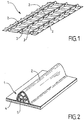
- Plate 1 shown on figure 1 is a corrugated plate, made of stainless steel, of generally rectangular shape.
- the primary waterproof membrane of the tank is made by welding edge to edge several plates of this type.
- plate 1 comprises three large waves 2 extending along the length of plate 1, and nine small waves 3 extending along the width of plate 1.
- large waves 2 and small waves 3 we speak of large waves 2 and small waves 3 because the height large waves 2 is greater than that of small waves 3.
- the plate 1 could have a different number of large waves 2 and / or small waves 3. Also in a variant, the waves of the plate 1 could have reinforcing ribs as described in FR 2 861 060 . The waves of plate 1 could also present other configurations, for example as in the documents FR 2 735 847 or KR-10-2005-0050170 .
- the plate 1 rests on the plywood 4 of the underlying thermally insulating layer.
- the plate 1 could rest on another type of support.
- a reinforcing element 5 is arranged under the large wave 2, between the plate 1 and the plywood 4.
- "under” means that the reinforcing element 5 is covered by the wave, but does not necessarily mean that it is lower. Indeed, on the vertical walls of the tank, the reinforcing element 5 is located horizontally to the wave which covers it.
- the length of the reinforcing element 5 corresponds to the distance between two small waves 3.
- reinforcing elements 5 can be arranged, each under a large wave 2 between two small waves 3.
- the number and distribution of the reinforcing elements 5 can be determined as a function of the distribution of the stresses provided for in operation in the membrane of the tank. .
- the length of the reinforcing element 5 may be less than the distance between two small waves 3 or, if the geometry of the crossing between waves allows it, greater than this distance. Also as a variant, reinforcing elements 5 can be provided under the small waves 3.
- the reinforcing element 5 is put in place as shown in figure 2 , without being fixed either to the plate 1 or to the plywood 4. It can therefore possibly slide under the large wave 2.
- the manufacture of the tank therefore does not require a step of fixing the reinforcing elements 5.
- the reinforcement element 5 can be fixed to the membrane or to the plywood 4.
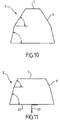
- the figures 3 to 11 represent different shapes that may be suitable.
- the views of figures 3 to 9 are perspective views of a portion of the reinforcing element 5, the length of which may be greater than that shown.
- the views of figures 10 and 11 are sectional views. In these different figures, the same reference signs are used to designate similar elements.
- the reinforcement element 5 of the figure 3 which is not part of the invention but is useful for understanding the invention, has a solid section. Its two side faces 6 are curved and have a shape corresponding to that of wave 2. However, the side faces 6 do not extend to the top of wave 2 and the reinforcing element 5 has an upper face. 7 plane. Gas can flow between the top of wave 2 and the top face 7.
- the reinforcement element 5 of the figure 4 has an envelope whose outer shape corresponds to the shape of the wave 2.
- a circular passage 9 allows gas to pass through the reinforcing element 5.
- the passage 9 has a shape corresponding to the outer shape of the casing, in order to provide a larger passage surface.
- the reinforcement element 5 of the figure 6 also has an envelope, the outer shape of which corresponds to the shape of the wave 2 and a passage 9.
- internal webs 10 pass through the passage 9.
- the figures 7 to 9 represent alternative configurations of sails 10.
- the reinforcement elements figures 3 to 9 can be made, for example, from one of the following materials: polyethylene, polycarbonate, polycarbonate reinforced with glass fibers, polyether imide, and expanded polystyrene. They can be manufactured by any suitable technique (injection, molding, extrusion, machining, etc.).
- the reinforcing elements 5 of the figures 10 and 11 which do not form part of the invention but are useful for understanding the invention, have a solid section. Their side faces 6 each have two flat bands. As for the reinforcing element of the figure 3 , gas can pass between the upper face 7 and the top of the wave.
- the reinforcing elements 5 of the figures 10 and 11 can for example be made of plywood, by machining.
- the reinforcement element 5 of the figure 11 has a tongue 22 fixed to its lower face 23.
- the tongue 23 makes it possible to fix the reinforcing element 5 to the plywood 4, for example at the level of the junction between two plywood plates.
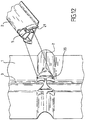
- the figure 12 shows, in the left part, the geometry of the waves at the level of a cross between a large wave 2 and a small wave 3. It can be seen that the membrane has at this level an undercut 20.
- the right part of the figure 12 shows that the reinforcing element 5 arranged under a large wave 2 has, at its end, tabs 21 which make it possible to fix the reinforcing element 5 to the membrane, by clipping at the level of the undercut 20. Alternatively, the legs 21 could be stuck.
- the figure 13 shows in perspective a reinforcing element 5 which is intended to be arranged simultaneously under several large waves 2 and small waves 3. Its shape corresponds to those of the waves, including at the crossings. Internal passages 9 are provided both in the parts located under the small waves 3 and under the large waves 2.
- the figure 14 which is not part of the invention but is useful for understanding the invention, shows two reinforcing elements 5, one being intended to be arranged under a large wave 2 and the other under a small wave 3 , by crossing at the crossing of the waves.
- the reinforcing elements 5 each have a notch 24 enabling them to be positioned relative to one another.
- the reinforcement elements 5 have a rectangular section.
- reinforcing element 5 allows the waves to deform in the event of thermal contraction, and provide support for the waves in the event of deformation due to hydrostatic and dynamic pressures. To achieve this goal, it can be provided that, when the tank is empty (therefore in the absence of thermal loading and hydrostatic or dynamic pressure), the minimum distance between the reinforcing element 5 and the wave under which it is finds either between 0% and 5% of the height of the wave.
- reinforcing element 5 each have particular properties: cost and ease of manufacture, mechanical strength, quantity of material, etc. Depending on the applications, the most appropriate form can be chosen.
Landscapes
- Engineering & Computer Science (AREA)
- Mechanical Engineering (AREA)
- Physics & Mathematics (AREA)
- Thermal Sciences (AREA)
- General Engineering & Computer Science (AREA)
- Filling Or Discharging Of Gas Storage Vessels (AREA)
- Chemical & Material Sciences (AREA)
- Combustion & Propulsion (AREA)
- Ocean & Marine Engineering (AREA)
- Separation Using Semi-Permeable Membranes (AREA)
Applications Claiming Priority (3)
| Application Number | Priority Date | Filing Date | Title |
|---|---|---|---|
| FR0805567A FR2936784B1 (fr) | 2008-10-08 | 2008-10-08 | Cuve a membrane ondulee renforcee |
| PCT/FR2009/051267 WO2010040922A1 (fr) | 2008-10-08 | 2009-06-30 | Cuve a membrane ondulée renforcée |
| EP09784452.6A EP2337984B1 (fr) | 2008-10-08 | 2009-06-30 | Cuve a membrane ondulée renforcée |
Related Parent Applications (3)
| Application Number | Title | Priority Date | Filing Date |
|---|---|---|---|
| EP09784452.6 Division | 2009-06-30 | ||
| EP09784452.6A Division EP2337984B1 (fr) | 2008-10-08 | 2009-06-30 | Cuve a membrane ondulée renforcée |
| EP09784452.6A Division-Into EP2337984B1 (fr) | 2008-10-08 | 2009-06-30 | Cuve a membrane ondulée renforcée |
Publications (3)
| Publication Number | Publication Date |
|---|---|
| EP2453159A2 EP2453159A2 (fr) | 2012-05-16 |
| EP2453159A3 EP2453159A3 (fr) | 2012-12-12 |
| EP2453159B1 true EP2453159B1 (fr) | 2020-07-29 |
Family
ID=40586195
Family Applications (3)
| Application Number | Title | Priority Date | Filing Date |
|---|---|---|---|
| EP12154056.1A Active EP2453159B1 (fr) | 2008-10-08 | 2009-06-30 | Cuve a membrane ondulée renforcée |
| EP12155836.5A Active EP2455650B1 (fr) | 2008-10-08 | 2009-06-30 | Cuve à membrane ondulée renforcée |
| EP09784452.6A Active EP2337984B1 (fr) | 2008-10-08 | 2009-06-30 | Cuve a membrane ondulée renforcée |
Family Applications After (2)
| Application Number | Title | Priority Date | Filing Date |
|---|---|---|---|
| EP12155836.5A Active EP2455650B1 (fr) | 2008-10-08 | 2009-06-30 | Cuve à membrane ondulée renforcée |
| EP09784452.6A Active EP2337984B1 (fr) | 2008-10-08 | 2009-06-30 | Cuve a membrane ondulée renforcée |
Country Status (12)
| Country | Link |
|---|---|
| EP (3) | EP2453159B1 (enExample) |
| JP (3) | JP5379234B2 (enExample) |
| KR (7) | KR20120031313A (enExample) |
| CN (3) | CN102177389A (enExample) |
| AU (1) | AU2009301016B2 (enExample) |
| BR (1) | BRPI0920667B1 (enExample) |
| ES (2) | ES2767975T3 (enExample) |
| FR (1) | FR2936784B1 (enExample) |
| MX (1) | MX2011003688A (enExample) |
| MY (2) | MY174853A (enExample) |
| RU (3) | RU2505737C2 (enExample) |
| WO (1) | WO2010040922A1 (enExample) |
Families Citing this family (35)
| Publication number | Priority date | Publication date | Assignee | Title |
|---|---|---|---|---|
| US20110186580A1 (en) * | 2008-03-03 | 2011-08-04 | Samsung Heavy Ind. Co., Ltd. | Reinforcing member for corrugated membrane of lng cargo tank, membrane assembly having the reinforcing member and method for constructing the same |
| FR2936784B1 (fr) * | 2008-10-08 | 2010-10-08 | Gaztransp Et Technigaz | Cuve a membrane ondulee renforcee |
| FR2963818B1 (fr) * | 2010-08-11 | 2014-01-03 | Gaztransp Et Technigaz | Structure de paroi etanche |
| KR101236746B1 (ko) | 2010-11-17 | 2013-02-25 | 삼성중공업 주식회사 | 액화천연가스 운반선의 멤브레인 보강재 |
| KR101337639B1 (ko) * | 2011-12-13 | 2013-12-05 | 삼성중공업 주식회사 | 액화천연가스 저장 탱크의 1차 방벽용 보강 부재의 결합 구조물 |
| KR101349875B1 (ko) * | 2011-12-16 | 2014-01-16 | 주식회사 티엠씨 | 액화천연가스 저장 탱크의 1차 방벽 보강 부재용 고정 구조체 |
| KR101337642B1 (ko) * | 2011-12-16 | 2013-12-05 | 삼성중공업 주식회사 | 액화천연가스 저장 탱크 및 그의 제조방법 |
| KR101349881B1 (ko) * | 2012-06-13 | 2014-01-16 | 삼성중공업 주식회사 | 액화천연가스 저장탱크의 1차 방벽용 보강 부재 고정 장치 |
| FR2998256B1 (fr) | 2012-11-16 | 2019-12-20 | Gaztransport Et Technigaz | Procede de fabrication d'une paroi de cuve etanche et thermiquement isolee |
| FR3009745B1 (fr) * | 2013-08-15 | 2016-01-29 | Gaztransp Et Technigaz | Cuve etanche et thermiquement isolante comportant une piece d'angle |
| CN104209080B (zh) * | 2014-09-09 | 2016-08-24 | 清华大学 | 舌形板波纹填料 |
| CN105561880B (zh) * | 2014-10-13 | 2018-08-10 | 彭碳科技有限公司 | 一种复合结构的含能容器 |
| FR3039248B1 (fr) * | 2015-07-24 | 2017-08-18 | Gaztransport Et Technigaz | Cuve etanche et thermiquement isolante munie d'une piece de renfort |
| FR3050008B1 (fr) * | 2016-04-11 | 2018-04-27 | Gaztransport Et Technigaz | Cuve etanche a membranes d'etancheite ondulees |
| KR102490347B1 (ko) * | 2016-10-24 | 2023-01-20 | 대우조선해양 주식회사 | 멤브레인 주름 보강구조체 및 이를 포함하는 lng 저장 탱크 |
| FR3061046B1 (fr) | 2016-12-23 | 2019-05-24 | Gaztransport Et Technigaz | Dispositif de pliage pour former une ondulation dans une tole metallique et procede d'utilisation dudit dispositif |
| WO2018173348A1 (ja) | 2017-03-22 | 2018-09-27 | 株式会社Ihi | 低温タンク及びその製造方法 |
| FR3074253B1 (fr) * | 2017-11-27 | 2019-11-01 | Gaztransport Et Technigaz | Cuve etanche et thermiquement isolante |
| FR3077278B1 (fr) | 2018-02-01 | 2020-02-07 | Gaztransport Et Technigaz | Paroi etanche a membrane ondulee renforcee |
| FR3083789B1 (fr) * | 2018-07-13 | 2020-07-10 | Gaztransport Et Technigaz | Paroi de cuve comportant une membrane d'etancheite presentant une ondulation ayant une portion curviligne renforcee |
| FR3084438B1 (fr) * | 2018-07-26 | 2020-07-31 | Gaztransport Et Technigaz | Cuve etanche et thermiquement isolante |
| FR3084346B1 (fr) * | 2018-07-27 | 2020-12-25 | Gaztransport Et Technigaz | Paroi etanche a membrane ondulee renforcee |
| FR3087871B1 (fr) * | 2018-10-31 | 2022-09-09 | Gaztransport Et Technigaz | Securisation de pieces de liaison au bord d’une plaque constitutive d’une cuve etanche a membranes ondules |
| FR3094338B1 (fr) * | 2019-03-26 | 2021-09-10 | Gaztransport Et Technigaz | Dispositif de maintien de renforts d’ondes lors de l’installation d’une paroi de cuve. |
| CN112124523B (zh) * | 2020-04-21 | 2022-10-14 | 沪东中华造船(集团)有限公司 | 一种用于Mark3型液货舱薄膜加强楔的安装方法 |
| CN112145954B (zh) * | 2020-09-21 | 2022-04-26 | 浙江振申绝热科技股份有限公司 | 一种膜式低温储罐的金属内罐的罐底结构 |
| FR3133900B1 (fr) | 2022-03-28 | 2024-07-12 | Gaztransport Et Technigaz | Cuve étanche et thermiquement isolante |
| FR3135773B1 (fr) | 2022-05-23 | 2024-11-15 | Gaztransport Et Technigaz | Cuve etanche et thermiquement isolante integree dans une structure porteuse |
| CN115817725A (zh) * | 2022-12-12 | 2023-03-21 | 中太海事技术(上海)有限公司 | 一种波纹膜的布置形式 |
| FR3159424B1 (fr) | 2024-02-16 | 2026-01-02 | Gaztransport Et Technigaz | Procédé de montage d’un angle de cuve |
| FR3160006A1 (fr) | 2024-03-07 | 2025-09-12 | Gaztransport Et Technigaz | Structure d’angle pour cuve etanche et thermiquement isolante et cuve comportant une telle structure d’angle |
| FR3160445A1 (fr) | 2024-03-20 | 2025-09-26 | Gaztransport Et Technigaz | Cuve étanche et thermiquement isolante |
| FR3160752A1 (fr) | 2024-04-02 | 2025-10-03 | Gaztransport Et Technigaz | Paroi étanche et thermiquement isolante |
| FR3164268A1 (fr) | 2024-07-08 | 2026-01-09 | Gaztransport Et Technigaz | Cuve étanche et thermiquement isolante |
| CN120402785B (zh) * | 2025-07-02 | 2025-09-05 | 中太能源科技(上海)有限公司 | 一种波纹支撑结构、薄膜围护系统及薄膜围护安装工艺 |
Family Cites Families (34)
| Publication number | Priority date | Publication date | Assignee | Title |
|---|---|---|---|---|
| US3341051A (en) * | 1964-12-24 | 1967-09-12 | Exxon Research Engineering Co | Cryogenic insulation system |
| JPS43290Y1 (enExample) * | 1966-05-30 | 1968-01-09 | ||
| SU820673A3 (ru) * | 1974-01-24 | 1981-04-07 | Текнигаз С.А. (Фирма) | Термоизол ционна стенка резервуара |
| JPS53160816U (enExample) * | 1977-05-24 | 1978-12-16 | ||
| JPS5452317A (en) * | 1977-10-04 | 1979-04-24 | Ishikawajima Harima Heavy Ind Co Ltd | Double shell roof membrane type low temperture underground tank |
| JPS5559024U (enExample) * | 1978-10-17 | 1980-04-22 | ||
| JPS5578896A (en) | 1978-12-12 | 1980-06-13 | Kawasaki Heavy Ind Ltd | Membrane structure of low temperature tank |
| JPS55122600U (enExample) * | 1979-02-23 | 1980-08-30 | ||
| JPS55122600A (en) * | 1979-03-15 | 1980-09-20 | Matsushita Electric Industrial Co Ltd | Steam iron |
| JPS56109993A (en) * | 1980-02-05 | 1981-08-31 | Ishikawajima Harima Heavy Ind Co Ltd | Expansion joint used in fluid storing tank at corner part of its side wall |
| JPS5710598U (enExample) * | 1980-06-20 | 1982-01-20 | ||
| JPS57165900U (enExample) * | 1981-04-14 | 1982-10-19 | ||
| JPS6098296A (ja) * | 1983-10-31 | 1985-06-01 | Mitsubishi Heavy Ind Ltd | 低温用波形伸縮継手 |
| JPS6098298A (ja) * | 1983-11-02 | 1985-06-01 | Mitsubishi Heavy Ind Ltd | 折曲げメンブレンコルゲ−シヨン |
| JPH02109885A (ja) * | 1988-10-14 | 1990-04-23 | Nkk Corp | ジャケット付き容器 |
| SU1610189A1 (ru) * | 1988-12-13 | 1990-11-30 | Институт Электросварки Им.Е.О.Патона | Баллон |
| FR2669396B1 (fr) * | 1990-11-19 | 1997-05-09 | Inst Francais Du Petrole | Reservoir de poids unitaire faible utilisable notamment pour le stockage de fluides sous pression et son procede de fabrication. |
| FR2706578B1 (fr) * | 1993-06-18 | 1995-09-01 | Inst Francais Du Petrole | Réservoir de stockage d'hydrocarbures sous pression. |
| FR2735847B1 (fr) | 1995-06-22 | 1997-08-14 | Korea Gas Corp | Membrane pour reservoir de stockage de gaz naturel liquefie |
| EP0855212B1 (en) * | 1995-09-21 | 2006-11-15 | Asahi Kasei Kabushiki Kaisha | Hollow fiber membrane module |
| DZ2535A1 (fr) * | 1997-06-20 | 2003-01-08 | Exxon Production Research Co | Procédé perfectionné pour la liquéfaction de gaz naturel. |
| FR2781557B1 (fr) * | 1998-07-24 | 2000-09-15 | Gaz Transport & Technigaz | Perfectionnement pour une cuve etanche et thermiquement isolante a panneaux prefabriques |
| US6547092B1 (en) * | 2000-11-14 | 2003-04-15 | Solomon Chervatsky | Pressure vessel with thin unstressed metallic liner |
| JP2002181288A (ja) * | 2000-12-14 | 2002-06-26 | Ishikawajima Harima Heavy Ind Co Ltd | 低温液化ガスメンブレンタンク |
| FR2861060B1 (fr) * | 2003-10-16 | 2006-01-06 | Gaz Transport & Technigaz | Structure de paroi etanche et cuve munie d'une telle structure |
| KR100706509B1 (ko) | 2003-11-25 | 2007-04-11 | 현대중공업 주식회사 | Lng 운반선 단열탱크의 멤브레인 금속패널 |
| KR100750487B1 (ko) * | 2004-02-02 | 2007-08-22 | 현대중공업 주식회사 | 부분 평면 용접부를 갖는 lng 운반선 단열탱크의멤브레인 금속패널 |
| US7456493B2 (en) * | 2005-04-15 | 2008-11-25 | Alps Electric Co., Ltd. | Structure for mounting semiconductor part in which bump and land portion are hardly detached from each other and method of manufacturing mounting substrate used therein |
| WO2008007837A1 (en) * | 2006-07-11 | 2008-01-17 | Hyundai Heavy Industries Co., Ltd. | Seam butt type insulation system having weldable secondary barrier for lng tanks |
| US20110186580A1 (en) * | 2008-03-03 | 2011-08-04 | Samsung Heavy Ind. Co., Ltd. | Reinforcing member for corrugated membrane of lng cargo tank, membrane assembly having the reinforcing member and method for constructing the same |
| AU2009279756B2 (en) | 2008-08-05 | 2015-01-29 | Omeros Corporation | PDE10 inhibitors and related compositions and methods |
| FR2936784B1 (fr) * | 2008-10-08 | 2010-10-08 | Gaztransp Et Technigaz | Cuve a membrane ondulee renforcee |
| JP2012066539A (ja) | 2010-09-27 | 2012-04-05 | Toppan Printing Co Ltd | メタルマスクおよびそのメタルマスクを用いたはんだペースト印刷方法 |
| JP2012066540A (ja) | 2010-09-27 | 2012-04-05 | Panasonic Corp | ガスバリア性フィルム |
-
2008
- 2008-10-08 FR FR0805567A patent/FR2936784B1/fr not_active Expired - Fee Related
-
2009
- 2009-06-30 JP JP2011530521A patent/JP5379234B2/ja active Active
- 2009-06-30 MY MYPI2014002054A patent/MY174853A/en unknown
- 2009-06-30 ES ES09784452T patent/ES2767975T3/es active Active
- 2009-06-30 RU RU2011116959/06A patent/RU2505737C2/ru active
- 2009-06-30 KR KR1020127006125A patent/KR20120031313A/ko not_active Abandoned
- 2009-06-30 WO PCT/FR2009/051267 patent/WO2010040922A1/fr not_active Ceased
- 2009-06-30 KR KR1020217043168A patent/KR20220003163A/ko not_active Ceased
- 2009-06-30 ES ES12154056T patent/ES2821391T3/es active Active
- 2009-06-30 BR BRPI0920667-1A patent/BRPI0920667B1/pt not_active IP Right Cessation
- 2009-06-30 RU RU2012107912/06A patent/RU2533271C2/ru active
- 2009-06-30 KR KR1020117010310A patent/KR20110070998A/ko not_active Ceased
- 2009-06-30 CN CN2009801398437A patent/CN102177389A/zh active Pending
- 2009-06-30 CN CN201210056610.4A patent/CN102588733B/zh active Active
- 2009-06-30 AU AU2009301016A patent/AU2009301016B2/en not_active Ceased
- 2009-06-30 KR KR1020147007291A patent/KR20140042936A/ko not_active Ceased
- 2009-06-30 MY MYPI2011001568A patent/MY154077A/en unknown
- 2009-06-30 EP EP12154056.1A patent/EP2453159B1/fr active Active
- 2009-06-30 EP EP12155836.5A patent/EP2455650B1/fr active Active
- 2009-06-30 RU RU2012105125/06A patent/RU2535293C2/ru active
- 2009-06-30 KR KR1020177026964A patent/KR102594126B1/ko active Active
- 2009-06-30 EP EP09784452.6A patent/EP2337984B1/fr active Active
- 2009-06-30 KR KR1020167004287A patent/KR101645155B1/ko active Active
- 2009-06-30 CN CN201210056536.6A patent/CN102588732B/zh active Active
- 2009-06-30 KR KR1020127006124A patent/KR20120031312A/ko not_active Ceased
- 2009-06-30 MX MX2011003688A patent/MX2011003688A/es active IP Right Grant
-
2012
- 2012-03-23 JP JP2012066539A patent/JP5778606B2/ja active Active
- 2012-03-23 JP JP2012066540A patent/JP5379258B2/ja active Active
Non-Patent Citations (1)
| Title |
|---|
| None * |
Also Published As
Similar Documents
| Publication | Publication Date | Title |
|---|---|---|
| EP2453159B1 (fr) | Cuve a membrane ondulée renforcée | |
| EP3198186B1 (fr) | Cuve étanche et isolante comportant un élément de pontage entre les panneaux de la barrière isolante secondaire | |
| EP3746377B1 (fr) | Paroi de cuve étanche, procédé de montage de paroi de cuve étanche, navire, procédé de chargement/déchargement d'un navire, système de transfert pour un produit liquide froid | |
| EP3365592B1 (fr) | Cuve comprenant des blocs isolants de coin equipes de fentes de relaxation | |
| EP3004718B1 (fr) | Caisse autoporteuse pour l'isolation thermique d'une cuve de stockage d'un fluide et procede de fabrication d'une telle caisse | |
| WO2017017337A1 (fr) | Cuve etanche et thermiquement isolante munie d'une piece de renfort | |
| FR3084347A1 (fr) | Paroi etanche a membrane ondulee renforcee | |
| EP3055606B1 (fr) | Caisse autoporteuse pour l'isolation thermique d'une cuve de stockage d'un fluide et procede de fabrication d'une telle caisse | |
| FR3102228A1 (fr) | Cuve étanche et thermiquement isolante | |
| EP3004719B1 (fr) | Procede de fabrication d'une caisse autoporteuse pour l'isolation thermique d'une cuve de stockage d'un fluide et caisse autoporteuse ainsi realisee | |
| EP3596383B1 (fr) | Cuve étanche et thermiquement isolante comportant un bouchon isolant de renfort | |
| FR3115093A1 (fr) | Cuve étanche et thermiquement isolante | |
| FR3084346A1 (fr) | Paroi etanche a membrane ondulee renforcee | |
| WO2022090341A1 (fr) | Cuve étanche et thermiquement isolante | |
| EP3821167B1 (fr) | Paroi de cuve comportant une membrane d'étanchéite présentant une ondulation ayant une portion curviligne renforcée | |
| FR3118118A1 (fr) | Cuve étanche et thermiquement isolante comportant un élément de pontage | |
| WO2020165537A1 (fr) | Bloc isolant destine a l'isolation thermique d'une cuve de stockage | |
| WO2022013031A1 (fr) | Cuve étanche et thermiquement isolante | |
| FR3094453A1 (fr) | Installation de stockage pour gaz liquéfié | |
| FR3115853A1 (fr) | Cuve étanche et thermiquement isolante | |
| WO2024125850A1 (fr) | Cuve étanche et thermiquement isolante comportant un élément traversant | |
| WO2024125849A1 (fr) | Cuve étanche et thermiquement isolante comportant un élément traversant | |
| FR3112587A1 (fr) | Cuve étanche et thermiquement isolante | |
| FR3077513A1 (fr) | Pilier entretoise | |
| WO2024115505A1 (fr) | Paroi pour une cuve étanche et thermiquement isolante de stockage d'un gaz liquéfié |
Legal Events
| Date | Code | Title | Description |
|---|---|---|---|
| PUAI | Public reference made under article 153(3) epc to a published international application that has entered the european phase |
Free format text: ORIGINAL CODE: 0009012 |
|
| AC | Divisional application: reference to earlier application |
Ref document number: 2337984 Country of ref document: EP Kind code of ref document: P |
|
| AK | Designated contracting states |
Kind code of ref document: A2 Designated state(s): AT BE BG CH CY CZ DE DK EE ES FI FR GB GR HR HU IE IS IT LI LT LU LV MC MK MT NL NO PL PT RO SE SI SK TR |
|
| TPAC | Observations filed by third parties |
Free format text: ORIGINAL CODE: EPIDOSNTIPA |
|
| PUAL | Search report despatched |
Free format text: ORIGINAL CODE: 0009013 |
|
| AK | Designated contracting states |
Kind code of ref document: A3 Designated state(s): AT BE BG CH CY CZ DE DK EE ES FI FR GB GR HR HU IE IS IT LI LT LU LV MC MK MT NL NO PL PT RO SE SI SK TR |
|
| RIC1 | Information provided on ipc code assigned before grant |
Ipc: F17C 3/02 20060101AFI20121107BHEP |
|
| 17P | Request for examination filed |
Effective date: 20130117 |
|
| TPAC | Observations filed by third parties |
Free format text: ORIGINAL CODE: EPIDOSNTIPA |
|
| 17Q | First examination report despatched |
Effective date: 20140206 |
|
| RAP1 | Party data changed (applicant data changed or rights of an application transferred) |
Owner name: GAZTRANSPORT ET TECHNIGAZ S.A. |
|
| RAP1 | Party data changed (applicant data changed or rights of an application transferred) |
Owner name: GAZTRANSPORT ET TECHNIGAZ |
|
| STAA | Information on the status of an ep patent application or granted ep patent |
Free format text: STATUS: EXAMINATION IS IN PROGRESS |
|
| GRAP | Despatch of communication of intention to grant a patent |
Free format text: ORIGINAL CODE: EPIDOSNIGR1 |
|
| STAA | Information on the status of an ep patent application or granted ep patent |
Free format text: STATUS: GRANT OF PATENT IS INTENDED |
|
| INTG | Intention to grant announced |
Effective date: 20200227 |
|
| GRAS | Grant fee paid |
Free format text: ORIGINAL CODE: EPIDOSNIGR3 |
|
| GRAA | (expected) grant |
Free format text: ORIGINAL CODE: 0009210 |
|
| STAA | Information on the status of an ep patent application or granted ep patent |
Free format text: STATUS: THE PATENT HAS BEEN GRANTED |
|
| AC | Divisional application: reference to earlier application |
Ref document number: 2337984 Country of ref document: EP Kind code of ref document: P |
|
| AK | Designated contracting states |
Kind code of ref document: B1 Designated state(s): AT BE BG CH CY CZ DE DK EE ES FI FR GB GR HR HU IE IS IT LI LT LU LV MC MK MT NL NO PL PT RO SE SI SK TR |
|
| REG | Reference to a national code |
Ref country code: GB Ref legal event code: FG4D Free format text: NOT ENGLISH |
|
| REG | Reference to a national code |
Ref country code: CH Ref legal event code: EP |
|
| REG | Reference to a national code |
Ref country code: AT Ref legal event code: REF Ref document number: 1296216 Country of ref document: AT Kind code of ref document: T Effective date: 20200815 |
|
| REG | Reference to a national code |
Ref country code: IE Ref legal event code: FG4D Free format text: LANGUAGE OF EP DOCUMENT: FRENCH |
|
| REG | Reference to a national code |
Ref country code: DE Ref legal event code: R096 Ref document number: 602009062524 Country of ref document: DE |
|
| REG | Reference to a national code |
Ref country code: NL Ref legal event code: FP |
|
| REG | Reference to a national code |
Ref country code: LT Ref legal event code: MG4D |
|
| REG | Reference to a national code |
Ref country code: NO Ref legal event code: T2 Effective date: 20200729 |
|
| REG | Reference to a national code |
Ref country code: AT Ref legal event code: MK05 Ref document number: 1296216 Country of ref document: AT Kind code of ref document: T Effective date: 20200729 |
|
| PG25 | Lapsed in a contracting state [announced via postgrant information from national office to epo] |
Ref country code: PT Free format text: LAPSE BECAUSE OF FAILURE TO SUBMIT A TRANSLATION OF THE DESCRIPTION OR TO PAY THE FEE WITHIN THE PRESCRIBED TIME-LIMIT Effective date: 20201130 Ref country code: SE Free format text: LAPSE BECAUSE OF FAILURE TO SUBMIT A TRANSLATION OF THE DESCRIPTION OR TO PAY THE FEE WITHIN THE PRESCRIBED TIME-LIMIT Effective date: 20200729 Ref country code: FI Free format text: LAPSE BECAUSE OF FAILURE TO SUBMIT A TRANSLATION OF THE DESCRIPTION OR TO PAY THE FEE WITHIN THE PRESCRIBED TIME-LIMIT Effective date: 20200729 Ref country code: LT Free format text: LAPSE BECAUSE OF FAILURE TO SUBMIT A TRANSLATION OF THE DESCRIPTION OR TO PAY THE FEE WITHIN THE PRESCRIBED TIME-LIMIT Effective date: 20200729 Ref country code: HR Free format text: LAPSE BECAUSE OF FAILURE TO SUBMIT A TRANSLATION OF THE DESCRIPTION OR TO PAY THE FEE WITHIN THE PRESCRIBED TIME-LIMIT Effective date: 20200729 Ref country code: AT Free format text: LAPSE BECAUSE OF FAILURE TO SUBMIT A TRANSLATION OF THE DESCRIPTION OR TO PAY THE FEE WITHIN THE PRESCRIBED TIME-LIMIT Effective date: 20200729 Ref country code: BG Free format text: LAPSE BECAUSE OF FAILURE TO SUBMIT A TRANSLATION OF THE DESCRIPTION OR TO PAY THE FEE WITHIN THE PRESCRIBED TIME-LIMIT Effective date: 20201029 Ref country code: GR Free format text: LAPSE BECAUSE OF FAILURE TO SUBMIT A TRANSLATION OF THE DESCRIPTION OR TO PAY THE FEE WITHIN THE PRESCRIBED TIME-LIMIT Effective date: 20201030 |
|
| PG25 | Lapsed in a contracting state [announced via postgrant information from national office to epo] |
Ref country code: PL Free format text: LAPSE BECAUSE OF FAILURE TO SUBMIT A TRANSLATION OF THE DESCRIPTION OR TO PAY THE FEE WITHIN THE PRESCRIBED TIME-LIMIT Effective date: 20200729 Ref country code: LV Free format text: LAPSE BECAUSE OF FAILURE TO SUBMIT A TRANSLATION OF THE DESCRIPTION OR TO PAY THE FEE WITHIN THE PRESCRIBED TIME-LIMIT Effective date: 20200729 Ref country code: IS Free format text: LAPSE BECAUSE OF FAILURE TO SUBMIT A TRANSLATION OF THE DESCRIPTION OR TO PAY THE FEE WITHIN THE PRESCRIBED TIME-LIMIT Effective date: 20201129 |
|
| REG | Reference to a national code |
Ref country code: ES Ref legal event code: FG2A Ref document number: 2821391 Country of ref document: ES Kind code of ref document: T3 Effective date: 20210426 |
|
| PG25 | Lapsed in a contracting state [announced via postgrant information from national office to epo] |
Ref country code: DK Free format text: LAPSE BECAUSE OF FAILURE TO SUBMIT A TRANSLATION OF THE DESCRIPTION OR TO PAY THE FEE WITHIN THE PRESCRIBED TIME-LIMIT Effective date: 20200729 Ref country code: EE Free format text: LAPSE BECAUSE OF FAILURE TO SUBMIT A TRANSLATION OF THE DESCRIPTION OR TO PAY THE FEE WITHIN THE PRESCRIBED TIME-LIMIT Effective date: 20200729 Ref country code: CZ Free format text: LAPSE BECAUSE OF FAILURE TO SUBMIT A TRANSLATION OF THE DESCRIPTION OR TO PAY THE FEE WITHIN THE PRESCRIBED TIME-LIMIT Effective date: 20200729 |
|
| REG | Reference to a national code |
Ref country code: DE Ref legal event code: R097 Ref document number: 602009062524 Country of ref document: DE |
|
| PLBE | No opposition filed within time limit |
Free format text: ORIGINAL CODE: 0009261 |
|
| STAA | Information on the status of an ep patent application or granted ep patent |
Free format text: STATUS: NO OPPOSITION FILED WITHIN TIME LIMIT |
|
| PG25 | Lapsed in a contracting state [announced via postgrant information from national office to epo] |
Ref country code: SK Free format text: LAPSE BECAUSE OF FAILURE TO SUBMIT A TRANSLATION OF THE DESCRIPTION OR TO PAY THE FEE WITHIN THE PRESCRIBED TIME-LIMIT Effective date: 20200729 |
|
| 26N | No opposition filed |
Effective date: 20210430 |
|
| PG25 | Lapsed in a contracting state [announced via postgrant information from national office to epo] |
Ref country code: SI Free format text: LAPSE BECAUSE OF FAILURE TO SUBMIT A TRANSLATION OF THE DESCRIPTION OR TO PAY THE FEE WITHIN THE PRESCRIBED TIME-LIMIT Effective date: 20200729 |
|
| REG | Reference to a national code |
Ref country code: DE Ref legal event code: R119 Ref document number: 602009062524 Country of ref document: DE |
|
| PG25 | Lapsed in a contracting state [announced via postgrant information from national office to epo] |
Ref country code: MC Free format text: LAPSE BECAUSE OF FAILURE TO SUBMIT A TRANSLATION OF THE DESCRIPTION OR TO PAY THE FEE WITHIN THE PRESCRIBED TIME-LIMIT Effective date: 20200729 |
|
| REG | Reference to a national code |
Ref country code: CH Ref legal event code: PL |
|
| REG | Reference to a national code |
Ref country code: BE Ref legal event code: MM Effective date: 20210630 |
|
| PG25 | Lapsed in a contracting state [announced via postgrant information from national office to epo] |
Ref country code: LU Free format text: LAPSE BECAUSE OF NON-PAYMENT OF DUE FEES Effective date: 20210630 |
|
| PG25 | Lapsed in a contracting state [announced via postgrant information from national office to epo] |
Ref country code: LI Free format text: LAPSE BECAUSE OF NON-PAYMENT OF DUE FEES Effective date: 20210630 Ref country code: IE Free format text: LAPSE BECAUSE OF NON-PAYMENT OF DUE FEES Effective date: 20210630 Ref country code: DE Free format text: LAPSE BECAUSE OF NON-PAYMENT OF DUE FEES Effective date: 20220101 Ref country code: CH Free format text: LAPSE BECAUSE OF NON-PAYMENT OF DUE FEES Effective date: 20210630 |
|
| PG25 | Lapsed in a contracting state [announced via postgrant information from national office to epo] |
Ref country code: BE Free format text: LAPSE BECAUSE OF NON-PAYMENT OF DUE FEES Effective date: 20210630 |
|
| PG25 | Lapsed in a contracting state [announced via postgrant information from national office to epo] |
Ref country code: HU Free format text: LAPSE BECAUSE OF FAILURE TO SUBMIT A TRANSLATION OF THE DESCRIPTION OR TO PAY THE FEE WITHIN THE PRESCRIBED TIME-LIMIT; INVALID AB INITIO Effective date: 20090630 Ref country code: CY Free format text: LAPSE BECAUSE OF FAILURE TO SUBMIT A TRANSLATION OF THE DESCRIPTION OR TO PAY THE FEE WITHIN THE PRESCRIBED TIME-LIMIT Effective date: 20200729 |
|
| P01 | Opt-out of the competence of the unified patent court (upc) registered |
Effective date: 20230614 |
|
| PG25 | Lapsed in a contracting state [announced via postgrant information from national office to epo] |
Ref country code: MK Free format text: LAPSE BECAUSE OF FAILURE TO SUBMIT A TRANSLATION OF THE DESCRIPTION OR TO PAY THE FEE WITHIN THE PRESCRIBED TIME-LIMIT Effective date: 20200729 |
|
| PGFP | Annual fee paid to national office [announced via postgrant information from national office to epo] |
Ref country code: NL Payment date: 20240524 Year of fee payment: 16 |
|
| PGFP | Annual fee paid to national office [announced via postgrant information from national office to epo] |
Ref country code: RO Payment date: 20240603 Year of fee payment: 16 |
|
| PGFP | Annual fee paid to national office [announced via postgrant information from national office to epo] |
Ref country code: TR Payment date: 20240607 Year of fee payment: 16 |
|
| PG25 | Lapsed in a contracting state [announced via postgrant information from national office to epo] |
Ref country code: MT Free format text: LAPSE BECAUSE OF FAILURE TO SUBMIT A TRANSLATION OF THE DESCRIPTION OR TO PAY THE FEE WITHIN THE PRESCRIBED TIME-LIMIT Effective date: 20200729 |
|
| PGFP | Annual fee paid to national office [announced via postgrant information from national office to epo] |
Ref country code: IT Payment date: 20240607 Year of fee payment: 16 |
|
| PGFP | Annual fee paid to national office [announced via postgrant information from national office to epo] |
Ref country code: GB Payment date: 20250625 Year of fee payment: 17 |
|
| PGFP | Annual fee paid to national office [announced via postgrant information from national office to epo] |
Ref country code: NO Payment date: 20250530 Year of fee payment: 17 |
|
| PGFP | Annual fee paid to national office [announced via postgrant information from national office to epo] |
Ref country code: FR Payment date: 20250630 Year of fee payment: 17 |
|
| PGFP | Annual fee paid to national office [announced via postgrant information from national office to epo] |
Ref country code: ES Payment date: 20250710 Year of fee payment: 17 |