EP2453056A1 - Vorrichtung zum Bügeln - Google Patents
Vorrichtung zum Bügeln Download PDFInfo
- Publication number
- EP2453056A1 EP2453056A1 EP10401193A EP10401193A EP2453056A1 EP 2453056 A1 EP2453056 A1 EP 2453056A1 EP 10401193 A EP10401193 A EP 10401193A EP 10401193 A EP10401193 A EP 10401193A EP 2453056 A1 EP2453056 A1 EP 2453056A1
- Authority
- EP
- European Patent Office
- Prior art keywords
- ironing board
- housing
- fan
- ironing
- board surface
- Prior art date
- Legal status (The legal status is an assumption and is not a legal conclusion. Google has not performed a legal analysis and makes no representation as to the accuracy of the status listed.)
- Granted
Links
Images



Classifications
-
- D—TEXTILES; PAPER
- D06—TREATMENT OF TEXTILES OR THE LIKE; LAUNDERING; FLEXIBLE MATERIALS NOT OTHERWISE PROVIDED FOR
- D06F—LAUNDERING, DRYING, IRONING, PRESSING OR FOLDING TEXTILE ARTICLES
- D06F81/00—Ironing boards
- D06F81/08—Ironing boards incorporating heating, steaming, or forced ventilation means
Definitions
- the invention relates to a device for ironing comprising an ironing board, a steam generator for an iron or ironing board and a blower device for generating an air stream which flows through an air and / or vapor permeable ironing board surface, wherein below the ironing board surface a hinged frame is arranged, which in collapsed state rests on the underside of the ironing board surface.
- blowers are integrated in or at the station, which accelerate the drying of the ironing cover, prevent the formation of condensation within the ironing board and being fixed or inflated for the operator during the ironing process, the textile material.
- the blower devices take a relatively large amount of space due to the function, and thereby specify the dimensions and contour of the ironing board.
- the known ironing board housing has a large volume for receiving the blower device, on which the crossed legs of a rack are stored on the board housing base when the station is not in use. When folded total device then lie on the legs of the frame on the housing.
- the fan is mounted at a small distance parallel below the ironing board surface to ensure the lowest possible storage volume of the entire device.
- the invention thus raises the problem of a device for ironing, which comprises an ironing board, a steam generator and a blower device to continue to form that on the one hand prevents the disadvantages described, the device is to be further formed so that it occupies a small storage space ,
- the advantages achieved with the invention consist in the fact that the solution of the distance between the fan device for ironing board underside in the operating state is great to achieve optimum flow conditions, whereas when dismantling, here pooling of the device, this is then reduced to a minimum, thus a the smallest possible storage volume is created.
- the blowing device is folded in an advantageous manner by the frame legs inwards against the ironing board underside. In the construction of the device, the blowing device is automatically pressed by spring and / or gravity back out to a slightly angled operating position. This also allows in contrast to the previously known systems, a relatively uniform pressure distribution up to the ironing board tip.
- the blower device As a blowing device which generates an overpressure below the ironing board surface and inflates the overlay slightly, thereby providing a soft air cushion between the ironing board surface and the overlay.
- the blowing device is integrated in the plane of the ironing board surface, and this can be brought into the stowed position by unfolding the frame into the operating position or by folding the frame.
- the blower device In the operating position, the blower device can be activated and in the stowed position it is deactivated or it can not be activated by the user.
- the fact that the blower device lies in the plane of the ironing board surface it is ensured that in particular the folding frame under the ironing board surface can be placed almost parallel to the underside of the ironing board surface, this plan is accommodated lying on the bottom. If the blower device to be put into operation, or the ironing board surface is placed on the frame, so the fan device pivots automatically and is thus ready for ironing.
- the fan device comprises at least one fan which is pivotally mounted in the plane of the ironing board surface.
- the fan is arranged in a housing which is arranged with a pivot bearing within the ironing board body.
- the fan in the housing comprises an axial fan, which sucks in particular the air below the ironing board here and then forwards them in a flow space within the ironing board or ironing board housing to the ironing board surface to the ironing board tip.
- the pivot bearing is arranged in the upper rear region of the housing.
- a stop for limiting the pivoting of the housing is provided on the housing in the front upper housing portion.
- the pivot bearing is arranged in the lower rear region of the housing. This results in the swinging a slightly larger flow space, as in the above embodiment.
- the housing comprises a fan assembly of at least two fans.
- the housing in the operating position of the fan preferably assumes an acute angle to the ironing board surface, based on the cross-sectional area of the air flow. Due to this design it is achieved that the sucked air flows at an obtuse angle to the underside of the ironing board, whereby due to the inclination and the flow space shape generated thereby a substantially homogeneous pressure or vacuum distribution is provided below the ironing board surface up to the board tip.
- a slight dynamic pressure or a slight negative pressure then generates the conveyed air a slight overpressure / negative pressure on the textile surface on the ironing board surface.
- the so-called tension on the textile ironing board cover is then generated, which is particularly advantageous when driving over the iron.
- An optimal pressure distribution is achieved by the free flow space within the ironing board.
- the ironing board surface is pivotally mounted to the frame on a stationary device.
- the ironing board surface is designed as a flow channel for the blowing device.
- the steam generator is housed in the state of the art.
- the stand device has for the process on a pair of rollers and a handle member. This configuration now allows on the one hand easy easy folding of the ironing board frame can be made, which can be easily applied to the steam generator, which is designed as a carriage, so that a movable ironing device is provided, which is easy and easy to handle, wherein their stowage due to the inventive design of the blower device, thereby significantly improved in the plane of the ironing board surface.
- the blower device acts in two flow directions.
- a blowing device which generates only an overpressure or a suction device which generates only a negative pressure can also be used.
- the FIG. 1 shows a device 1 for ironing comprising an ironing board 2, a steam generator 3, for a non-illustrated iron, and a blower device 4 for generating an air stream 5, as shown for example in the FIG. 1 is shown with the indicated arrow.
- the air flow 5 flows through an air and / or vapor permeable ironing board surface 6, wherein below the ironing board surface 6 a hinged frame 7 is arranged.
- the frame 7 In the collapsed state, the frame 7 is located on the underside of the ironing board, as for example in the FIG. 4 is shown.
- the blower device 4 as such shown in the Figures 2 and 3 , is hereby integrated in the plane of the ironing board surface 6, wherein by unfolding, FIG. 2 , the frame 7, the fan device 4 is moved to the operating position and activated.
- the blowing device 4 is spent in the stowage position and is deactivated here.
- the fan device 4 in this case comprises at least one fan 8, which is arranged pivotably in the plane of the ironing board surface 6.
- the fan 8 is arranged in a housing 9, which is arranged with a pivot bearing 10 in the ironing board body.
- the fan 8 in this case comprises in the housing 9 an axial fan.
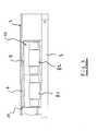
- the pivot bearing 10 is disposed in the upper rear region of the housing 9, wherein the housing 9 in the front upper housing portion a stop 11 is provided to limit the pivoting of the housing 9, as shown in particular from FIG. 2 it can be seen where the pivot bearing 10 and the stop 11 are clearly visible. It goes without saying that, if now the frame 7 is swung open and occupies the position as shown in the FIG.
- the housing 9 in which the axial fan is housed, automatically by gravity in an angled position, the so-called operating position, pivots.
- the housing 9 has approximately the strength of the ironing board 2, this being clearer in the FIG. 3 it can be seen where the housing 9 virtually disappears in the thickness of the ironing board 2, when it is pivoted.
- the housing 9 comprises a fan assembly of at least two fans 8.1 and 8.2, as shown in the two representations of Figures 2 and 3 will be shown.
- the housing 9 of the fans 8.1 and 8.2 resp.
- the flat top makes an acute angle to the ironing board surface 6, as shown in FIG FIG. 2 is shown. It goes without saying that due to this inclination now the sucked air is pressed against the underside of the ironing board 2 against the upper surface of the ironing board 2, so that there is an enlarged flow space within the ironing board or the ironing board body in this acute angular position.
- the ironing board surface 6 is pivotally mounted to the frame 7 on a stationary device 12, wherein in the floor unit 12 here the steam generator can be integrated.
- the ironing board surface 6 is designed as a flow channel, as already described, for the blower device 4.
- this includes the stand unit 12 a pair of rollers 13, and in the upper part of a handle member 14, so that in the folded state of the ironing board surface 6 on the floor unit 12 this can be easily moved, and thus an optimized storage position of the ironing board surface 6 on the Stand device 12 results.
Landscapes
- Engineering & Computer Science (AREA)
- Textile Engineering (AREA)
- Irons (AREA)
Abstract
Description
- Die Erfindung betrifft eine Vorrichtung zum Bügeln umfassend ein Bügelbrett, einen Dampferzeuger für ein Bügeleisen oder Bügelbrett sowie eine Gebläsevorrichtung zur Erzeugung eines Luftstromes, der durch eine luft- und/oder dampfdurchlässige Bügelbrettfläche strömt, wobei unterhalb der Bügelbrettfläche ein klappbares Gestell angeordnet ist, welches im zusammengelegten Zustand an der Unterseite der Bügelbrettfläche anliegt.
- Bei sogenannten Dampfbügelstationen werden Gebläse in bzw. an der Station integriert, welche das Trocknen des Bügelbezugs beschleunigen, die Kondensationsbildung innerhalb des Bügelbrettes verhindern und wobei für den Bediener während des Bügelprozesses das Textilgut fixiert bzw. aufgeblasen werden soll. Dabei nehmen die Gebläseeinrichtungen funktionsbedingt einen relativ großen Bauraum ein, und geben dadurch die Abmaße sowie Kontur des Bügelbretts vor. So weist das bekannte Bügelbrettgehäuse ein großes Volumen zur Aufnahme der Gebläseeinrichtung auf, auf das die gekreuzten Beine eines Gestells an der Brettgehäuseunterseite gelagert werden, wenn die Station nicht in Benutzung ist. Beim zusammengefalteten Gesamtgerät liegen dann die Beine des Gestells auf dem Gehäuse auf. Bei den bekannten Bügelstationen wird das Gebläse mit geringem Abstand parallel unterhalb der Bügelbrettoberfläche angebracht, um ein möglichst geringes Verstauvolumen des Gesamtgerätes zu gewährleisten. Eine solche Anordnung des Gebläses hat zur Folge, dass zum Bügelbrett auf diesem flächenmäßig kleinen Bereich eine hohe Druckspitze vorhanden ist, welche in den angrenzenden Bereichen des Bügelbrettes mit zunehmender Entfernung sehr stark abnimmt. So ist an der Brettspitze der Gebläseeffekt kaum noch vorhanden, was dort dann neben dem Fehlen der unterstützenden Funktion für das Bügeln auch noch zu unerwünschter Kondensatansammlung bzw. feuchter Bügelbrettoberfläche führt.
- Aus dem Stand der Technik gemäß der
DE 102 04 745 A1 ist eine Dampfbügelvorrichtung bekannt, welche die geschilderten Nachteile aufweist. Dabei weist die Dampfbügelvorrichtung ein Bügelbrett auf, das eine luft- oder dampfdurchlässige Brettfläche aufweist. Dabei ist die Blasvorrichtung in einem unterhalb des Bügelbrettteils angeordneten Gehäuse untergebracht. Aufgrund dieser Ausbildung kann zwar die Dampfbügelvorrichtung zusammengefaltet werden, hat jedoch den Nachteil, dass sie einen großen Verstauraum einnimmt. - Der Erfindung stellt sich somit das Problem eine Vorrichtung zum Bügeln, welche ein Bügelbrett, einen Dampferzeuger sowie eine Gebläsevorrichtung umfasst, derart weiter zu bilden, die einerseits die geschilderten Nachteile unterbindet, wobei die Vorrichtung dahingehend weiter gebildet werden soll, dass sie einen geringen Stauraum einnimmt.
- Erfindungsgemäß wird dieses Problem durch eine Vorrichtung zum Bügeln mit den Merkmalen des unabhängigen Patentanspruchs 1 gelöst. Vorteilhafte Ausgestaltungen und Weiterbildungen der Erfindung ergeben sich aus den nachfolgenden abhängigen Ansprüchen.
- Die mit der Erfindung erreichten Vorteile bestehen nun darin, dass durch das Lösungskonzept der Abstand der Gebläsevorrichtung zur Bügelbrettunterseite im Betriebszustand groß ist, um optimale Strömungsverhältnisse zu erreichen, wohingegen beim Abbau, hier Zusammenlegen der Vorrichtung, dieser dann auf ein Minimum reduziert wird, damit ein möglichst geringes Verstauvolumen entsteht. Die Blasvorrichtung wird in vorteilhafter Weise durch die Gestellbeine nach innen gegen die Bügelbrettunterseite geklappt. Beim Aufbau der Vorrichtung wird die Blasvorrichtung durch Feder- und/oder Schwerkraft automatisch wieder nach außen in eine leicht winklige Betriebsposition gedrückt. Dies ermöglicht zudem im Gegensatz zu den bisher bekannten Systemen eine relativ gleichmäßige Druckverteilung bis hin zur Bügelbrettspitze. Auch bei der Erzeugung eines Unterdrucks wird erreicht, dass der Unterdruck bis in die Brettspitze wirkt und die Auflage gegen die Bügelbrettfläche ansaugt und Dampf absaugt. Für empfindliche Textilien ist es zweckmäßig, die Gebläsevorrichtung als Blasvorrichtung zu betreiben, die einen Überdruck unterhalb der Bügelbrettfläche erzeugt und die Auflage etwas aufbläst und dadurch ein weiches Luftpolster zwischen Bügelbrettfläche und Auflage bereitstellt.
- Gemäß der Erfindung wird vorgeschlagen, dass die Blasvorrichtung hierbei in der Ebene der Bügelbrettfläche integriert ist, und wobei diese durch Aufklappen des Gestells in die Betriebslage bzw. durch Einklappen des Gestells in die Verstauposition gebracht werden kann. In der Betriebslage ist die Gebläsevorrichtung aktivierbar und in der Verstauposition ist sie deaktiviert bzw. sie kann dann nicht vom Benutzer aktiviert werden. Dadurch, dass die Gebläsevorrichtung in der Ebene der Bügelbrettfläche liegt, wird sichergestellt, dass insbesondere das Klappgestell unter der Bügelbrettfläche quasi parallel an die Unterseite der Bügelbrettfläche gelegt werden kann, wobei dieses plan liegend an der Unterseite untergebracht wird. Soll die Gebläsevorrichtung in Betrieb genommen werden, bzw. wird die Bügelbrettfläche auf das Gestell aufgestellt, so schwenkt die Gebläsevorrichtung selbsttätig aus und steht somit für den Bügelvorgang bereit. Nach einer vorteilhaften Ausgestaltung der Erfindung umfasst die Gebläsevorrichtung wenigstens einen Ventilator, der in der Ebene der Bügelbrettfläche schwenkbar angeordnet ist. Dabei ist der Ventilator in einem Gehäuse angeordnet, welches mit einem Schwenklager innerhalb des Bügelbrettkörpers angeordnet ist. Hierbei ist es besonders vorteilhaft, dass der Ventilator in dem Gehäuse einen Axiallüfter umfasst, der insbesondere die Luft unterhalb des Bügelbretts hier ansaugt und sie dann in einem Strömungsraum innerhalb des Bügelbretts oder Bügelbrettgehäuses zur Bügelbrettfläche bis in die Bügelbrettspitze weiterleitet.
- Nach einer vorteilhaften Ausgestaltung der Erfindung ist das Schwenklager im oberen hinteren Bereich des Gehäuses angeordnet. Dabei ist am Gehäuse im vorderen oberen Gehäusebereich ein Anschlag zur Begrenzung der Schwenkbarkeit des Gehäuses vorgesehen. Diese Ausbildung bewirkt, dass aufgrund der gegebenen Schwerkraft des Gehäuses mit innen liegendem Axiallüfter, dieses selbsttätig heraus schwenkt, wenn das Gestell unterhalb der Bügelbrettfläche aufgefaltet wird. Hierzu schwenkt das Gehäuse durch seine Schwerkraft in die Betriebslage des Ventilators. In Weiterbildung der Erfindung weist das Gehäuse etwa die Stärke des Bügelbretts auf.
- In einer alternativen Ausführung ist das Schwenklager im unteren hinteren Bereich des Gehäuses angeordnet. Dadurch ergibt sich beim Aufschwenken ein etwas größerer Strömungsraum, wie bei der oben genannten Ausführung.
- Dabei umfasst das Gehäuse eine Lüfterbaugruppe von wenigstens zwei Ventilatoren. Hierbei nimmt das Gehäuse in der Betriebslage des Ventilators vorzugsweise einen spitzen Winkel zur Bügelbrettfläche ein, bezogen auf die Querschnittsfläche der Luftströmung. Aufgrund dieser Ausbildung wird erreicht, dass die angesaugte Luft unter einem stumpfen Winkel auf die Unterseite des Bügelbretts strömt, wobei dadurch aufgrund der Schrägstellung und der dadurch erzeugten Strömungsraumform eine im Wesentlichen homogene Druck- oder Unterdruckverteilung unterhalb der Bügelbrettfläche bis hin zur Brettspitze bereitgestellt wird. Infolge eines leichten Staudrucks bzw. eines leichten Unterdrucks erzeugt dann die geförderte Luft einen leichten Überdruck / Unterdruck an der Textilfläche auf der Bügelbrettfläche. Dadurch wird dann die so genannte Spannkraft am textilen Bügelbrettüberzug erzeugt, die insbesondere beim Überfahren mit dem Bügeleisen von Vorteil ist. Eine optimale Druckverteilung wird durch den freien Strömungsraum innerhalb des Bügelbretts erreicht.
- Nach einer besonders vorteilhaften Ausgestaltung der Erfindung ist die Bügelbrettfläche mit dem Gestell an einem Standgerät schwenkbar gelagert. Dabei ist die Bügelbrettfläche als Strömungskanal für die Blasvorrichtung ausgebildet. Nach einer vorteilhaften Ausgestaltung ist hierbei in dem Standgerät der Dampferzeuger untergebracht. Das Standgerät weist zum Verfahren ein Rollenpaar sowie ein Griffelement auf. Diese Ausbildung ermöglicht es nun, dass einerseits ein leichtes einfaches Zusammenfalten des Bügelbrettgestells vorgenommen werden kann, welches an den Dampferzeuger, der als Wagen ausgebildet ist, leicht angelegt werden kann, so dass eine verfahrbare Bügelvorrichtung bereitgestellt wird, die leicht und einfach zu handhaben ist, wobei deren Verstaumöglichkeit infolge der erfindungsgemäßen Ausgestaltung der Gebläsevorrichtung, in der Ebene der Bügelbrettfläche dadurch wesentlich verbessert wird.
- Wie bereits oben erläutert, wirkt die Gebläsevorrichtung in zwei Strömungsrichtungen. Alternativ kann auch eine Blasvorrichtung, die nur einen Überdruck erzeugt oder eine Saugvorrichtung, die nur einen Unterdruck erzeugt, verwendet werden.
- Ein Ausführungsbeispiel der Erfindung ist in den Zeichnungen rein schematisch dargestellt und wird nachfolgend näher beschrieben. Es zeigt
- Figur 1
- eine Seitenansicht einer Vorrichtung zum Bügeln in der aufgefalteten Situation bzw. in der Betriebsstellung;
- Figur 2
- eine Detailansicht der Gebläsevorrichtung in der Bügelbrettfläche in der aktivierten Stellung;
- Figur 3
- eine weitere Detailansicht der Gebläsevorrichtung in der inaktivierten Stellung; und
- Figur 4
- eine Seitenansicht der Vorrichtung im zusammengefalteten Zustand.
- Die
Figur 1 zeigt eine Vorrichtung 1 zum Bügeln umfassend ein Bügelbrett 2, einen Dampferzeuger 3, für ein nicht näher dargestelltes Bügeleisen, sowie eine Gebläsevorrichtung 4 zur Erzeugung eines Luftstromes 5, wie er beispielsweise in derFigur 1 mit dem angedeuteten Pfeil dargestellt ist. Der Luftstrom 5 strömt hierbei durch eine luft- und/oder dampfdurchlässige Bügelbrettfläche 6, wobei unterhalb der Bügelbrettfläche 6 ein klappbares Gestell 7 angeordnet ist. Im zusammengelegten Zustand liegt das Gestell 7 an der Unterseite des Bügelbrettes an, wie dies beispielsweise in derFigur 4 dargestellt ist. Die Gebläsevorrichtung 4 als solches, dargestellt in denFiguren 2 und3 , ist hierbei in der Ebene der Bügelbrettfläche 6 integriert, wobei durch Aufklappen,Figur 2 , des Gestells 7 die Gebläsevorrichtung 4 in die Betriebslage verbracht und aktiviert wird. Durch Zusammenklappen des Gestells 7, wie dies in derFigur 3 dargestellt ist, wird die Blasvorrichtung 4 in die Verstaulage verbracht und wird hierbei deaktiviert. - Die Gebläsevorrichtung 4 umfasst hierbei wenigstens einen Ventilator 8, der in der Ebene der Bügelbrettfläche 6 schwenkbar angeordnet ist. Der Ventilator 8 ist in einem Gehäuse 9 angeordnet, welches mit einem Schwenklager 10 im Bügelbrettkörper angeordnet ist. Der Ventilator 8 umfasst hierbei in dem Gehäuse 9 einen Axiallüfter. Dabei ist das Schwenklager 10 im oberen hinteren Bereich des Gehäuses 9 angeordnet, wobei am Gehäuse 9 im vorderen oberen Gehäusebereich ein Anschlag 11 zur Begrenzung der Schwenkbarkeit des Gehäuses 9 vorgesehen ist, wie dies insbesondere aus der
Figur 2 zu erkennen ist, wo das Schwenklager 10 und auch der Anschlag 11 deutlich zu erkennen sind. Es versteht sich von selbst, dass, wenn nun das Gestell 7 aufgeschwenkt ist und die Stellung einnimmt, wie sie in derFigur 1 dargestellt ist, dann das Gehäuse 9, in dem der Axiallüfter untergebracht ist, selbsttätig aufgrund der Schwerkraft in eine gewinkelte Lage, die sogenannte Betriebsposition, verschwenkt. Wie aus denFiguren 2 und3 zu erkennen ist, weist das Gehäuse 9 etwa die Stärke des Bügelbretts 2 auf, wobei dies deutlicher in derFigur 3 zu erkennen ist, wo das Gehäuse 9 quasi in der Dicke des Bügelbretts 2 verschwindet, wenn es eingeschwenkt ist. - Dabei umfasst das Gehäuse 9 eine Lüfterbaugruppe von wenigstens zwei Ventilatoren 8.1 und 8.2, wie es in den beiden Darstellungen der
Figuren 2 und3 gezeigt wird. In der aktivierten Lage nimmt das Gehäuse 9 der Ventilatoren 8.1 und 8.2 bzw.- die flache Oberseite einen spitzen Winkel zur Bügelbrettfläche 6 ein, wie dies in derFigur 2 dargestellt ist. Es versteht sich nun von selbst, dass aufgrund dieser Schrägstellung nun die angesaugte Luft an der Unterseite des Bügelbrettes 2 gegen die obere Fläche des Bügelbretts 2 gedrückt wird, so dass sich in dieser spitzen Winkellage ein vergrößerter Strömungsraum innerhalb des Bügelbretts bzw. des Bügelbrettkörpers ergibt. Bei eingeschaltetem Ventilator 8 ergibt sich im Strömungsraum ein leichter Staudruck, so dass die Oberflächenbespannung sich hier leicht gewölbt ausbildet, weil der Strömungsdruck sich über die Länge des Bügelbretts 2 abbaut, so wie dies durch die Pfeildarstellung in derFigur 1 dargestellt wird. Somit ergibt sich auf der Oberfläche des Bügelbrettes 2 eine gewölbte Lage der textilen Auflage, die derart spannt, dass die gespannte Auflage ein erleichtertes Bügeln bereitstellt. Es versteht sich von selbst, dass die Bügelbrettfläche 6 perforiert, luftdurchlässig oder als Gitter ausgebildet ist, damit die Luft auf die Oberflächenbespannung wirken kann. - Nach einer besonders vorteilhaften Ausgestaltung der Erfindung, dargestellt in der
Figur 4 , ist die Bügelbrettfläche 6 mit dem Gestell 7 an einem Standgerät 12 schwenkbar gelagert, wobei in dem Standgerät 12 hier der Dampferzeuger integriert sein kann. Dabei ist die Bügelbrettfläche 6 als Strömungskanal, wie bereits beschrieben, für die Gebläsevorrichtung 4 ausgebildet. Wie aus derFigur 4 zu erkennen ist, umfasst hierbei das Standgerät 12 ein Rollenpaar 13, sowie im oberen Bereich ein Griffelement 14, so dass im zusammengefalteten Zustand der Bügelbrettfläche 6 an dem Standgerät 12 dieses leicht verfahren werden kann, und sich somit eine optimierte Verstaulage der Bügelbrettfläche 6 an dem Standgerät 12 ergibt.
Claims (15)
- Vorrichtung (1) zum Bügeln umfassend ein Bügelbrett (2), einen Dampferzeuger (3) für ein Bügeleisen oder Bügelbrett (2) sowie eine Blasvorrichtung (4) zur Erzeugung eines Luftstromes (5), der durch eine luft- und/oder dampfdurchlässige Bügelbrettfläche (6) strömt, wobei unterhalb der Bügelbrettfläche (6) ein klappbares Gestell (7) angeordnet ist, welches im zusammengelegten Zustand an der Unterseite der Bügelbrettfläche (6) anliegt, dadurch gekennzeichnet,
dass die Gebläsevorrichtung (4) in der Ebene der Bügelbrettfläche (6) bzw. innerhalb des Bügelbretts (2) integriert ist, und wobei diese durch Aufklappen des Gestells (7) in die Betriebsposition bzw. durch Einklappen des Gestells (7) in die Verstauposition gebracht werden kann. - Vorrichtung nach Anspruch 1,
dadurch gekennzeichnet,
dass die Gebläsevorrichtung (4) wenigstens einen Ventilator (8) umfasst, der in der Ebene der Bügelbrettfläche (6) schwenkbar angeordnet ist. - Vorrichtung nach Anspruch 2,
dadurch gekennzeichnet,
dass der Ventilator (8) in einem Gehäuse (9) angeordnet ist, welches mit einem Schwenklager (10) im Bügelbrettkörper angeordnet ist. - Vorrichtung nach Anspruch 3,
dadurch gekennzeichnet,
dass der Ventilator (8) in dem Gehäuse (9) einen Axial-Lüfter umfasst. - Vorrichtung nach Anspruch 4,
dadurch gekennzeichnet,
dass das Schwenklager (10) im oberen hinteren Bereich des Gehäuses (9) angeordnet ist. - Vorrichtung nach Anspruch 4,
dadurch gekennzeichnet,
dass das Schwenklager (10) im unteren hinteren Bereich des Gehäuses (9) angeordnet ist. - Vorrichtung nach Anspruch 4, 5 oder 6,
dadurch gekennzeichnet,
dass am Gehäuse (9) im vorderen oberen Gehäusebereich ein Anschlag (11) zur Begrenzung der Schwenkbarkeit des Gehäuses (9) vorgesehen ist. - Vorrichtung nach Anspruch 5 oder 6,
dadurch gekennzeichnet,
dass die Gebläsevorrichtung (4) mit ihrem Gehäuse (9) durch Schwerkraft selbsttätig in die Betriebslage des Ventilators (8) schwenkt. - Vorrichtung nach Anspruch 4 bis 8,
dadurch gekennzeichnet,
dass das Gehäuse (9) etwa die Stärke des Bügelbrettes (2) aufweist. - Vorrichtung nach Anspruch 1,
dadurch gekennzeichnet,
dass das Gehäuse (9) eine Lüfterbaugruppe von wenigstens zwei Ventilatoren (8.1) und (8.2) umfasst. - Vorrichtung nach Anspruch 5 bis 10,
dadurch gekennzeichnet,
dass das Gehäuse (9) in der Betriebslage der Ventilatoren (8.1, 8.2) einen spitzen Winkel zur Bügelbrettfläche (6) einnimmt. - Vorrichtung nach Anspruch 1,
dadurch gekennzeichnet,
dass das Bügelbrett(2) oder der Bügelbrettkörper als Strömungskanal für die Gebläsevorrichtung (4) ausgebildet ist. - Vorrichtung nach Anspruch 1,
dadurch gekennzeichnet,
dass die Bügelbrettfläche (6) mit dem Gestell (7) an einem Standgerät (12) schwenkbar gelagert ist. - Vorrichtung nach Anspruch 13,
dadurch gekennzeichnet,
dass in dem Standgerät (12) der Dampferzeuger untergebracht ist. - Vorrichtung nach Anspruch 13 oder 14,
dadurch gekennzeichnet,
dass das Standgerät (12) zum Verfahren ein Rollenpaar (13) sowie ein Griffelement (14) umfasst.
Priority Applications (3)
| Application Number | Priority Date | Filing Date | Title |
|---|---|---|---|
| EP10401193A EP2453056B1 (de) | 2010-11-11 | 2010-11-11 | Vorrichtung zum Bügeln |
| PL10401193T PL2453056T3 (pl) | 2010-11-11 | 2010-11-11 | Urządzenie do prasowania |
| ES10401193T ES2401867T3 (es) | 2010-11-11 | 2010-11-11 | Equipo para planchar |
Applications Claiming Priority (1)
| Application Number | Priority Date | Filing Date | Title |
|---|---|---|---|
| EP10401193A EP2453056B1 (de) | 2010-11-11 | 2010-11-11 | Vorrichtung zum Bügeln |
Publications (2)
| Publication Number | Publication Date |
|---|---|
| EP2453056A1 true EP2453056A1 (de) | 2012-05-16 |
| EP2453056B1 EP2453056B1 (de) | 2013-03-06 |
Family
ID=43888628
Family Applications (1)
| Application Number | Title | Priority Date | Filing Date |
|---|---|---|---|
| EP10401193A Active EP2453056B1 (de) | 2010-11-11 | 2010-11-11 | Vorrichtung zum Bügeln |
Country Status (3)
| Country | Link |
|---|---|
| EP (1) | EP2453056B1 (de) |
| ES (1) | ES2401867T3 (de) |
| PL (1) | PL2453056T3 (de) |
Cited By (1)
| Publication number | Priority date | Publication date | Assignee | Title |
|---|---|---|---|---|
| CN114652092A (zh) * | 2022-03-10 | 2022-06-24 | 上海工程技术大学 | 一种服装设计工作台 |
Citations (4)
| Publication number | Priority date | Publication date | Assignee | Title |
|---|---|---|---|---|
| DE10204745A1 (de) * | 2001-03-30 | 2002-10-10 | Vorwerk Co Interholding | Dampfbügelvorrichtung |
| EP1277873A1 (de) * | 2001-07-19 | 2003-01-22 | Euro Star S.r.l. | Dampfbügelvorrichtung |
| WO2007007230A1 (en) * | 2005-07-07 | 2007-01-18 | Koninklijke Philips Electronics N.V. | Method for operating an active ironing board |
| GB2468717A (en) * | 2009-03-20 | 2010-09-22 | Vale Mill | Vacuum ironing board |
-
2010
- 2010-11-11 PL PL10401193T patent/PL2453056T3/pl unknown
- 2010-11-11 EP EP10401193A patent/EP2453056B1/de active Active
- 2010-11-11 ES ES10401193T patent/ES2401867T3/es active Active
Patent Citations (4)
| Publication number | Priority date | Publication date | Assignee | Title |
|---|---|---|---|---|
| DE10204745A1 (de) * | 2001-03-30 | 2002-10-10 | Vorwerk Co Interholding | Dampfbügelvorrichtung |
| EP1277873A1 (de) * | 2001-07-19 | 2003-01-22 | Euro Star S.r.l. | Dampfbügelvorrichtung |
| WO2007007230A1 (en) * | 2005-07-07 | 2007-01-18 | Koninklijke Philips Electronics N.V. | Method for operating an active ironing board |
| GB2468717A (en) * | 2009-03-20 | 2010-09-22 | Vale Mill | Vacuum ironing board |
Cited By (1)
| Publication number | Priority date | Publication date | Assignee | Title |
|---|---|---|---|---|
| CN114652092A (zh) * | 2022-03-10 | 2022-06-24 | 上海工程技术大学 | 一种服装设计工作台 |
Also Published As
| Publication number | Publication date |
|---|---|
| PL2453056T3 (pl) | 2013-06-28 |
| EP2453056B1 (de) | 2013-03-06 |
| ES2401867T3 (es) | 2013-04-25 |
Similar Documents
| Publication | Publication Date | Title |
|---|---|---|
| EP1349981B1 (de) | Vorrichtung zum glätten von hemden | |
| EP2130964A1 (de) | Wäschebehandlungsmaschine wie Waschmaschine, Wäschetrockner oder dergleichen | |
| EP2453056B1 (de) | Vorrichtung zum Bügeln | |
| WO2012093035A1 (de) | Diffusor eines haartrockners | |
| DE60202262T2 (de) | Bügeltisch mit saugvorrichtung und/oder blasvorrichtung | |
| DE102018217423A1 (de) | Mobiler Lüfter | |
| EP1346098B1 (de) | Vorrichtung zum glätten von hemden | |
| EP4263300A1 (de) | Vorrichtung und verfahren zur reinigung von zweirädern | |
| DE1254114B (de) | Buegelfaltenpressvorrichtung | |
| EP3216913B1 (de) | Wäschetrockner | |
| DE102017123989B4 (de) | Bügelunterlage | |
| EP1069231B1 (de) | Vorrichtung zum Glätten von Hemden | |
| EP4237614B1 (de) | Blähkörper und verwendung des blähkörpers in einem system zum trocknen und/oder glätten eines textilstückes | |
| EP1069230B1 (de) | Vorrichtung zum Glätten von Hemden mit Kragen | |
| DE102015106908B4 (de) | Dampfbügeltisch | |
| DE60315300T2 (de) | Ständertrageinrichtung | |
| DE10156859A1 (de) | Vorrichtung zum Glätten hemdförmiger Kleidungsstücke | |
| DE10032563B4 (de) | Tisch mit einer zur Abstützung an einer Wand eingerichteten, mit einer schwenkbaren Stütze versehenen Tischplatte | |
| EP1448834A1 (de) | Blähkörper zum glätten von hemdförmigen kleidungsstücken und vorrichtung zum glätten von kleidungsstücken mit einem solchen blähkörper | |
| WO2002050363A1 (de) | Bügelpuppe mit luftstromabhängiger luftumlenkung | |
| EP0556448B1 (de) | Verfahren, Vorrichtung und Mittel zur Fleckentfernung | |
| DE102022113391A1 (de) | Wärmerückgewinnungseinheit, Finisher-System und Finisher-Anordnung | |
| DE1557340B2 (de) | Haartrockner | |
| DE19938013A1 (de) | Vorrichtung zur Verlängerung von Stoffhosen | |
| DE9124C (de) | Neuerungen an mechanischen Trocken-Apparaten für ununterbrochenen Betrieb |
Legal Events
| Date | Code | Title | Description |
|---|---|---|---|
| PUAI | Public reference made under article 153(3) epc to a published international application that has entered the european phase |
Free format text: ORIGINAL CODE: 0009012 |
|
| 17P | Request for examination filed |
Effective date: 20110610 |
|
| AK | Designated contracting states |
Kind code of ref document: A1 Designated state(s): AL AT BE BG CH CY CZ DE DK EE ES FI FR GB GR HR HU IE IS IT LI LT LU LV MC MK MT NL NO PL PT RO RS SE SI SK SM TR |
|
| AX | Request for extension of the european patent |
Extension state: BA ME |
|
| GRAP | Despatch of communication of intention to grant a patent |
Free format text: ORIGINAL CODE: EPIDOSNIGR1 |
|
| GRAS | Grant fee paid |
Free format text: ORIGINAL CODE: EPIDOSNIGR3 |
|
| GRAA | (expected) grant |
Free format text: ORIGINAL CODE: 0009210 |
|
| AK | Designated contracting states |
Kind code of ref document: B1 Designated state(s): AL AT BE BG CH CY CZ DE DK EE ES FI FR GB GR HR HU IE IS IT LI LT LU LV MC MK MT NL NO PL PT RO RS SE SI SK SM TR |
|
| REG | Reference to a national code |
Ref country code: GB Ref legal event code: FG4D Free format text: NOT ENGLISH |
|
| REG | Reference to a national code |
Ref country code: AT Ref legal event code: REF Ref document number: 599703 Country of ref document: AT Kind code of ref document: T Effective date: 20130315 Ref country code: CH Ref legal event code: EP |
|
| REG | Reference to a national code |
Ref country code: IE Ref legal event code: FG4D Free format text: LANGUAGE OF EP DOCUMENT: GERMAN |
|
| REG | Reference to a national code |
Ref country code: GB Ref legal event code: 746 Effective date: 20130311 |
|
| REG | Reference to a national code |
Ref country code: ES Ref legal event code: GC2A Effective date: 20130401 |
|
| REG | Reference to a national code |
Ref country code: ES Ref legal event code: FG2A Ref document number: 2401867 Country of ref document: ES Kind code of ref document: T3 Effective date: 20130425 |
|
| REG | Reference to a national code |
Ref country code: CH Ref legal event code: NV Representative=s name: FIAMMENGHI-FIAMMENGHI, CH |
|
| REG | Reference to a national code |
Ref country code: DE Ref legal event code: R096 Ref document number: 502010002429 Country of ref document: DE Effective date: 20130508 |
|
| REG | Reference to a national code |
Ref country code: DE Ref legal event code: R084 Ref document number: 502010002429 Country of ref document: DE Effective date: 20130320 |
|
| REG | Reference to a national code |
Ref country code: PL Ref legal event code: T3 |
|
| PG25 | Lapsed in a contracting state [announced via postgrant information from national office to epo] |
Ref country code: NO Free format text: LAPSE BECAUSE OF FAILURE TO SUBMIT A TRANSLATION OF THE DESCRIPTION OR TO PAY THE FEE WITHIN THE PRESCRIBED TIME-LIMIT Effective date: 20130606 Ref country code: LT Free format text: LAPSE BECAUSE OF FAILURE TO SUBMIT A TRANSLATION OF THE DESCRIPTION OR TO PAY THE FEE WITHIN THE PRESCRIBED TIME-LIMIT Effective date: 20130306 Ref country code: BG Free format text: LAPSE BECAUSE OF FAILURE TO SUBMIT A TRANSLATION OF THE DESCRIPTION OR TO PAY THE FEE WITHIN THE PRESCRIBED TIME-LIMIT Effective date: 20130606 Ref country code: SE Free format text: LAPSE BECAUSE OF FAILURE TO SUBMIT A TRANSLATION OF THE DESCRIPTION OR TO PAY THE FEE WITHIN THE PRESCRIBED TIME-LIMIT Effective date: 20130306 |
|
| REG | Reference to a national code |
Ref country code: NL Ref legal event code: VDEP Effective date: 20130306 |
|
| REG | Reference to a national code |
Ref country code: LT Ref legal event code: MG4D |
|
| PG25 | Lapsed in a contracting state [announced via postgrant information from national office to epo] |
Ref country code: SI Free format text: LAPSE BECAUSE OF FAILURE TO SUBMIT A TRANSLATION OF THE DESCRIPTION OR TO PAY THE FEE WITHIN THE PRESCRIBED TIME-LIMIT Effective date: 20130306 Ref country code: LV Free format text: LAPSE BECAUSE OF FAILURE TO SUBMIT A TRANSLATION OF THE DESCRIPTION OR TO PAY THE FEE WITHIN THE PRESCRIBED TIME-LIMIT Effective date: 20130306 Ref country code: FI Free format text: LAPSE BECAUSE OF FAILURE TO SUBMIT A TRANSLATION OF THE DESCRIPTION OR TO PAY THE FEE WITHIN THE PRESCRIBED TIME-LIMIT Effective date: 20130306 Ref country code: GR Free format text: LAPSE BECAUSE OF FAILURE TO SUBMIT A TRANSLATION OF THE DESCRIPTION OR TO PAY THE FEE WITHIN THE PRESCRIBED TIME-LIMIT Effective date: 20130607 |
|
| PG25 | Lapsed in a contracting state [announced via postgrant information from national office to epo] |
Ref country code: RS Free format text: LAPSE BECAUSE OF FAILURE TO SUBMIT A TRANSLATION OF THE DESCRIPTION OR TO PAY THE FEE WITHIN THE PRESCRIBED TIME-LIMIT Effective date: 20130306 Ref country code: HR Free format text: LAPSE BECAUSE OF FAILURE TO SUBMIT A TRANSLATION OF THE DESCRIPTION OR TO PAY THE FEE WITHIN THE PRESCRIBED TIME-LIMIT Effective date: 20130306 |
|
| PG25 | Lapsed in a contracting state [announced via postgrant information from national office to epo] |
Ref country code: RO Free format text: LAPSE BECAUSE OF FAILURE TO SUBMIT A TRANSLATION OF THE DESCRIPTION OR TO PAY THE FEE WITHIN THE PRESCRIBED TIME-LIMIT Effective date: 20130306 Ref country code: EE Free format text: LAPSE BECAUSE OF FAILURE TO SUBMIT A TRANSLATION OF THE DESCRIPTION OR TO PAY THE FEE WITHIN THE PRESCRIBED TIME-LIMIT Effective date: 20130306 Ref country code: NL Free format text: LAPSE BECAUSE OF FAILURE TO SUBMIT A TRANSLATION OF THE DESCRIPTION OR TO PAY THE FEE WITHIN THE PRESCRIBED TIME-LIMIT Effective date: 20130306 Ref country code: SK Free format text: LAPSE BECAUSE OF FAILURE TO SUBMIT A TRANSLATION OF THE DESCRIPTION OR TO PAY THE FEE WITHIN THE PRESCRIBED TIME-LIMIT Effective date: 20130306 Ref country code: IS Free format text: LAPSE BECAUSE OF FAILURE TO SUBMIT A TRANSLATION OF THE DESCRIPTION OR TO PAY THE FEE WITHIN THE PRESCRIBED TIME-LIMIT Effective date: 20130706 Ref country code: PT Free format text: LAPSE BECAUSE OF FAILURE TO SUBMIT A TRANSLATION OF THE DESCRIPTION OR TO PAY THE FEE WITHIN THE PRESCRIBED TIME-LIMIT Effective date: 20130708 Ref country code: CZ Free format text: LAPSE BECAUSE OF FAILURE TO SUBMIT A TRANSLATION OF THE DESCRIPTION OR TO PAY THE FEE WITHIN THE PRESCRIBED TIME-LIMIT Effective date: 20130306 |
|
| REG | Reference to a national code |
Ref country code: PL Ref legal event code: LICE Effective date: 20130423 |
|
| PLBE | No opposition filed within time limit |
Free format text: ORIGINAL CODE: 0009261 |
|
| STAA | Information on the status of an ep patent application or granted ep patent |
Free format text: STATUS: NO OPPOSITION FILED WITHIN TIME LIMIT |
|
| PG25 | Lapsed in a contracting state [announced via postgrant information from national office to epo] |
Ref country code: DK Free format text: LAPSE BECAUSE OF FAILURE TO SUBMIT A TRANSLATION OF THE DESCRIPTION OR TO PAY THE FEE WITHIN THE PRESCRIBED TIME-LIMIT Effective date: 20130306 |
|
| 26N | No opposition filed |
Effective date: 20131209 |
|
| REG | Reference to a national code |
Ref country code: DE Ref legal event code: R097 Ref document number: 502010002429 Country of ref document: DE Effective date: 20131209 |
|
| PG25 | Lapsed in a contracting state [announced via postgrant information from national office to epo] |
Ref country code: MC Free format text: LAPSE BECAUSE OF FAILURE TO SUBMIT A TRANSLATION OF THE DESCRIPTION OR TO PAY THE FEE WITHIN THE PRESCRIBED TIME-LIMIT Effective date: 20130306 |
|
| REG | Reference to a national code |
Ref country code: IE Ref legal event code: MM4A |
|
| PG25 | Lapsed in a contracting state [announced via postgrant information from national office to epo] |
Ref country code: IE Free format text: LAPSE BECAUSE OF NON-PAYMENT OF DUE FEES Effective date: 20131111 |
|
| PG25 | Lapsed in a contracting state [announced via postgrant information from national office to epo] |
Ref country code: SM Free format text: LAPSE BECAUSE OF FAILURE TO SUBMIT A TRANSLATION OF THE DESCRIPTION OR TO PAY THE FEE WITHIN THE PRESCRIBED TIME-LIMIT Effective date: 20130306 |
|
| PG25 | Lapsed in a contracting state [announced via postgrant information from national office to epo] |
Ref country code: CY Free format text: LAPSE BECAUSE OF FAILURE TO SUBMIT A TRANSLATION OF THE DESCRIPTION OR TO PAY THE FEE WITHIN THE PRESCRIBED TIME-LIMIT Effective date: 20130306 Ref country code: TR Free format text: LAPSE BECAUSE OF FAILURE TO SUBMIT A TRANSLATION OF THE DESCRIPTION OR TO PAY THE FEE WITHIN THE PRESCRIBED TIME-LIMIT Effective date: 20130306 |
|
| PG25 | Lapsed in a contracting state [announced via postgrant information from national office to epo] |
Ref country code: HU Free format text: LAPSE BECAUSE OF FAILURE TO SUBMIT A TRANSLATION OF THE DESCRIPTION OR TO PAY THE FEE WITHIN THE PRESCRIBED TIME-LIMIT; INVALID AB INITIO Effective date: 20101111 Ref country code: LU Free format text: LAPSE BECAUSE OF NON-PAYMENT OF DUE FEES Effective date: 20131111 Ref country code: MK Free format text: LAPSE BECAUSE OF FAILURE TO SUBMIT A TRANSLATION OF THE DESCRIPTION OR TO PAY THE FEE WITHIN THE PRESCRIBED TIME-LIMIT Effective date: 20130306 |
|
| PG25 | Lapsed in a contracting state [announced via postgrant information from national office to epo] |
Ref country code: MT Free format text: LAPSE BECAUSE OF FAILURE TO SUBMIT A TRANSLATION OF THE DESCRIPTION OR TO PAY THE FEE WITHIN THE PRESCRIBED TIME-LIMIT Effective date: 20130306 |
|
| REG | Reference to a national code |
Ref country code: FR Ref legal event code: PLFP Year of fee payment: 6 |
|
| REG | Reference to a national code |
Ref country code: FR Ref legal event code: PLFP Year of fee payment: 7 |
|
| REG | Reference to a national code |
Ref country code: FR Ref legal event code: PLFP Year of fee payment: 8 |
|
| PG25 | Lapsed in a contracting state [announced via postgrant information from national office to epo] |
Ref country code: AL Free format text: LAPSE BECAUSE OF FAILURE TO SUBMIT A TRANSLATION OF THE DESCRIPTION OR TO PAY THE FEE WITHIN THE PRESCRIBED TIME-LIMIT Effective date: 20130306 |
|
| PGFP | Annual fee paid to national office [announced via postgrant information from national office to epo] |
Ref country code: IT Payment date: 20221122 Year of fee payment: 13 Ref country code: GB Payment date: 20221122 Year of fee payment: 13 Ref country code: FR Payment date: 20221122 Year of fee payment: 13 Ref country code: ES Payment date: 20221213 Year of fee payment: 13 |
|
| PGFP | Annual fee paid to national office [announced via postgrant information from national office to epo] |
Ref country code: PL Payment date: 20221010 Year of fee payment: 13 Ref country code: BE Payment date: 20221124 Year of fee payment: 13 |
|
| P01 | Opt-out of the competence of the unified patent court (upc) registered |
Effective date: 20230529 |
|
| GBPC | Gb: european patent ceased through non-payment of renewal fee |
Effective date: 20231111 |
|
| REG | Reference to a national code |
Ref country code: BE Ref legal event code: MM Effective date: 20231130 |
|
| PG25 | Lapsed in a contracting state [announced via postgrant information from national office to epo] |
Ref country code: GB Free format text: LAPSE BECAUSE OF NON-PAYMENT OF DUE FEES Effective date: 20231111 |
|
| PG25 | Lapsed in a contracting state [announced via postgrant information from national office to epo] |
Ref country code: BE Free format text: LAPSE BECAUSE OF NON-PAYMENT OF DUE FEES Effective date: 20231130 |
|
| PG25 | Lapsed in a contracting state [announced via postgrant information from national office to epo] |
Ref country code: FR Free format text: LAPSE BECAUSE OF NON-PAYMENT OF DUE FEES Effective date: 20231130 |
|
| PG25 | Lapsed in a contracting state [announced via postgrant information from national office to epo] |
Ref country code: GB Free format text: LAPSE BECAUSE OF NON-PAYMENT OF DUE FEES Effective date: 20231111 Ref country code: FR Free format text: LAPSE BECAUSE OF NON-PAYMENT OF DUE FEES Effective date: 20231130 Ref country code: BE Free format text: LAPSE BECAUSE OF NON-PAYMENT OF DUE FEES Effective date: 20231130 |
|
| PG25 | Lapsed in a contracting state [announced via postgrant information from national office to epo] |
Ref country code: IT Free format text: LAPSE BECAUSE OF NON-PAYMENT OF DUE FEES Effective date: 20231111 |
|
| PG25 | Lapsed in a contracting state [announced via postgrant information from national office to epo] |
Ref country code: IT Free format text: LAPSE BECAUSE OF NON-PAYMENT OF DUE FEES Effective date: 20231111 |
|
| REG | Reference to a national code |
Ref country code: ES Ref legal event code: FD2A Effective date: 20250102 |
|
| PG25 | Lapsed in a contracting state [announced via postgrant information from national office to epo] |
Ref country code: ES Free format text: LAPSE BECAUSE OF NON-PAYMENT OF DUE FEES Effective date: 20231112 |
|
| PG25 | Lapsed in a contracting state [announced via postgrant information from national office to epo] |
Ref country code: ES Free format text: LAPSE BECAUSE OF NON-PAYMENT OF DUE FEES Effective date: 20231112 |
|
| PG25 | Lapsed in a contracting state [announced via postgrant information from national office to epo] |
Ref country code: PL Free format text: LAPSE BECAUSE OF NON-PAYMENT OF DUE FEES Effective date: 20231111 |
|
| REG | Reference to a national code |
Ref country code: CH Ref legal event code: U11 Free format text: ST27 STATUS EVENT CODE: U-0-0-U10-U11 (AS PROVIDED BY THE NATIONAL OFFICE) Effective date: 20251201 |
|
| PGFP | Annual fee paid to national office [announced via postgrant information from national office to epo] |
Ref country code: DE Payment date: 20251130 Year of fee payment: 16 |
|
| PGFP | Annual fee paid to national office [announced via postgrant information from national office to epo] |
Ref country code: AT Payment date: 20251118 Year of fee payment: 16 |
|
| PGFP | Annual fee paid to national office [announced via postgrant information from national office to epo] |
Ref country code: CH Payment date: 20251201 Year of fee payment: 16 |