EP2452902B1 - Verbesserte Aufnahmeeinheit - Google Patents
Verbesserte Aufnahmeeinheit Download PDFInfo
- Publication number
- EP2452902B1 EP2452902B1 EP11183947.8A EP11183947A EP2452902B1 EP 2452902 B1 EP2452902 B1 EP 2452902B1 EP 11183947 A EP11183947 A EP 11183947A EP 2452902 B1 EP2452902 B1 EP 2452902B1
- Authority
- EP
- European Patent Office
- Prior art keywords
- picking assembly
- frame
- pick
- removable
- pick unit
- Prior art date
- Legal status (The legal status is an assumption and is not a legal conclusion. Google has not performed a legal analysis and makes no representation as to the accuracy of the status listed.)
- Active
Links
Images




Classifications
-
- B—PERFORMING OPERATIONS; TRANSPORTING
- B65—CONVEYING; PACKING; STORING; HANDLING THIN OR FILAMENTARY MATERIAL
- B65H—HANDLING THIN OR FILAMENTARY MATERIAL, e.g. SHEETS, WEBS, CABLES
- B65H1/00—Supports or magazines for piles from which articles are to be separated
- B65H1/04—Supports or magazines for piles from which articles are to be separated adapted to support articles substantially horizontally, e.g. for separation from top of pile
-
- B—PERFORMING OPERATIONS; TRANSPORTING
- B65—CONVEYING; PACKING; STORING; HANDLING THIN OR FILAMENTARY MATERIAL
- B65H—HANDLING THIN OR FILAMENTARY MATERIAL, e.g. SHEETS, WEBS, CABLES
- B65H2402/00—Constructional details of the handling apparatus
- B65H2402/10—Modular constructions, e.g. using preformed elements or profiles
-
- B—PERFORMING OPERATIONS; TRANSPORTING
- B65—CONVEYING; PACKING; STORING; HANDLING THIN OR FILAMENTARY MATERIAL
- B65H—HANDLING THIN OR FILAMENTARY MATERIAL, e.g. SHEETS, WEBS, CABLES
- B65H2402/00—Constructional details of the handling apparatus
- B65H2402/40—Details of frames, housings or mountings of the whole handling apparatus
- B65H2402/44—Housings
-
- B—PERFORMING OPERATIONS; TRANSPORTING
- B65—CONVEYING; PACKING; STORING; HANDLING THIN OR FILAMENTARY MATERIAL
- B65H—HANDLING THIN OR FILAMENTARY MATERIAL, e.g. SHEETS, WEBS, CABLES
- B65H2405/00—Parts for holding the handled material
- B65H2405/30—Other features of supports for sheets
- B65H2405/33—Compartmented support
- B65H2405/332—Superposed compartments
-
- B—PERFORMING OPERATIONS; TRANSPORTING
- B65—CONVEYING; PACKING; STORING; HANDLING THIN OR FILAMENTARY MATERIAL
- B65H—HANDLING THIN OR FILAMENTARY MATERIAL, e.g. SHEETS, WEBS, CABLES
- B65H2701/00—Handled material; Storage means
- B65H2701/10—Handled articles or webs
- B65H2701/19—Specific article or web
- B65H2701/1912—Banknotes, bills and cheques or the like
Definitions
- the present invention relates to improvements in or relating to a pick unit.
- a pick unit is part of a dispenser module, which is typically located in a self-service terminal (SST).
- a dispenser module typically includes a presenter unit for presenting picked media items to a customer, and one or more pick units, coupled to the presenter unit, for picking individual media items from one or more storage areas in the dispenser, and for transporting the picked media items to the presenter unit.
- Dispenser modules are commonly used in automated teller machines (ATMs) to dispense media items to customers. These media items are typically banknotes, but may comprise stamps, coupons, passes, or the like.
- Banknote dispensers typically include a removable currency cassette slidably located within each pick unit (see US 2003/0111317 disclosing an apparatus according to the preamble of claim 1).
- Each currency pick unit comprises one or more pick modules.
- a four-high pick unit may comprise two two-high pick modules coupled together.
- a two-high pick module refers to a module having two picking mechanisms (one above the other).
- a two-high pick unit may comprise a two-high pick module.
- Each picking mechanism comprises (i) a picking end, which removes media items from a cassette, and (ii) a loading end opposite the picking end.
- a currency cassette is inserted into, and removed from, the loading end.
- Picking media items from a cassette is a complex electro-mechanical operation, and the picked media items are prone to jamming. Thus, the picking operation accounts for a high percentage of dispenser failures. This means that service personnel have to replace pick units quite frequently. Pick units are relatively large and heavy, so replacing pick units requires the service personnel to take a large item (one or more spare pick units or pick modules) to an ATM site in case the pick unit (or a pick module within the pick unit) needs replaced. The size and weight of a pick unit (or pick module) means that the replacement operation is quite time consuming and physically difficult for service personnel to perform.
- the invention generally provides methods, systems, and apparatus for an improved pick unit comprising a fixed portion and a picking assembly removably coupled thereto, so that the picking assembly can be replaced without having to replace the fixed portion.
- a pick unit comprising:
- the tortuous pathway may define an underpass to move the gear train below the upper gear then an upright passage to move the gear train upwards and into engagement with the upper gear.
- the tortuous pathway may be configured to support the removable picking assembly via the cam follower when the removable picking assembly is in the engagement position.
- the tortuous pathway may comprise a hook shape.
- the removable picking assembly may further comprise one or more latches for coupling to an external unit above the pick unit.
- the external unit may comprise another pick unit or a presenter unit.
- the one or more latches may comprise overcenter toggle latches.
- the frame may define apertures which, when the removable picking assembly is moved to the engaged position, are in registration with apertures on the removable picking assembly, thereby allowing threaded fixtures (such as screws or bolts) to secure the removable picking assembly to the frame.
- the frame apertures may be threaded.
- the cam follower may comprise a stud.
- the stud may comprise a mushroom stud defining a stem dimensioned to be accommodated within the tortuous pathway, and a flange larger than the tortuous pathway to retain the stem within the tortuous pathway.
- the frame may include a vacuum generator.
- a vacuum generator may be located on an external unit (such as a presenter unit).
- the frame may include one or more frame pipes.
- the one or more frame pipes may include sealable couplings for connecting to other pipes and also for connecting to a vacuum generator.
- the removable picking assembly may further comprise a vacuum pick arm, a vacuum pipe in fluid communication with the vacuum pick arm, and a vacuum coupling for connecting the vacuum pipe to one of the frame pipes.
- a vacuum generator to convey reduced pressure to the vacuum pick arm to enable media items to be picked from a storage container mounted in the frame.
- the removable picking assembly may comprise a friction pick roller. Where a friction pick roller is used, no vacuum pipes or vacuum generator would be required.
- the storage container may comprise a currency cassette.
- the removable picking assembly may comprise a plurality of vacuum pick arms.
- a removable picking assembly may comprise two vacuum pick arms, each vacuum pick arm being aligned with a currency cassette, so that a single picking assembly can pick banknotes from either of two currency cassettes.
- the removable picking assembly may further comprise one or more tines engagable with a currency cassette loaded into the frame.
- the tines may raise a shutter in the currency cassette when the currency cassette is inserted into the pick unit.
- a media dispenser including the pick unit according to the first aspect.
- the media dispenser may include a presenter unit having a circuit board; the frame may further comprise a first electrical connection comprising a plurality of cables routed from the circuit board; and the removable picking assembly may further comprise a second electrical connection, interengagable with the first electrical connection, so that electrical power and data can be routed between the removable picking assembly and the presenter unit.
- a self-service terminal including the media dispenser according to the second aspect.
- a pick unit comprising:
- the frame may define a cam track.
- the cam track may be in the form of a non-straight pathway, including a raised projection near an entrance thereto.
- a picking assembly into engagement with a frame to provide a pick unit, the method comprising:
- a removable picking assembly for a pick unit comprising:
- the gear train may comprise a transfer gear to receive rotational power from the upper gear.
- the gear train may further comprise a power take-off gear to impart rotational power to any transfer gear on a removable picking assembly located beneath the picking assembly.
- Figs 1 and 2 are schematic front perspective views of a media dispenser 10 (in the form of a currency dispenser) including a four-high pick unit 12 according to one embodiment of the present invention, and a media presenter 14 (in the form of a banknote presenter) located above, and coupled to, the four-high pick unit 12.
- a media dispenser 10 in the form of a currency dispenser
- a media presenter 14 in the form of a banknote presenter
- the banknote presenter 14 comprises a body 16 and a nose 18 extending therefrom.
- the body 16 comprises sheet metal enclosing various belts and skid plates (as is known in the art) to collate banknotes received individually from the four-high pick unit 12, and to present the collated banknotes as a bunch via the nose 18.
- the body 16 also comprises a main motor (not shown) and a main gear 20 for providing power for mechanical devices (such as belts and pulleys) within the banknote dispenser 10 (both the banknote presenter 14 and the four-high pick unit 12).
- the main gear 20 rotates a hand gear 21 (so called because it can be rotated by hand by a service engineer when the power to the banknote presenter 14 is turned off), which rotates a transfer gear 22, which is used to transfer rotary power to the four-high pick unit 12.
- the body 16 also comprises a vacuum pump (not shown) for generating low pressure and a vacuum source pipe (not shown) in fluid communication with the vacuum pump (not shown).
- Fig 3 is a schematic front right perspective view of the four-high pick unit 12 of the currency dispenser 10.
- the four-high pick unit 12 comprises a frame 30 in the form of a pair of sheet metal sidewalls 31 a,b maintained in spaced relation by metal bars 32 extending therebetween.
- a vacuum feed pipe 33 (only a small part of this is visible in Fig 3 ) extends down an inner surface of one of the sidewalls 31 a.
- the vacuum feed pipe 33 couples to the vacuum source pipe (not shown).
- the four-high pick unit 12 further comprises a pair of mutually coupled two-high removable picking assemblies 34a,b coupled to the frame 30.
- One of these picking assemblies 34a is located above the other picking assembly 34b.
- the two picking assemblies 34a,b are identical to each other.
- Each picking assembly 34 includes a pair of overcenter toggle latches 36 near the top of the picking assembly 34.
- Each picking assembly 34 also defines a pair of pick latch projections 38 located near the bottom of the picking assembly 34 and vertically aligned with the overcenter toggle latches 36.
- the banknote presenter unit 14 defines a pair of presenter latch projections (not shown, but identical to the pick latch projections 38).
- the presenter latch projections (not shown) align with, and are complementary to, the toggle latches 36, to allow the toggle latches 36 to be secured thereto.
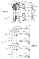
- Figs 4 and 5 illustrate one of the picking assemblies 34a in more detail.
- the picking assembly 34a comprises a pair of sheet metal sidewalls 40a,40b mutually separated by a lower plate 42 and spacer bars 44.
- the picking assembly 34a further comprises an upper pick arm 50a and a lower pick arm 50b.
- Each of the pick arms 50a,b is hollow and in fluid communication with vacuum pipes 52a,b, spaced from the sidewall 40b, and extending from the pick arms 50a,b through solenoid operated valves 54a,b to vacuum couplings 56a,b.
- the vacuum couplings 56a,b are used to couple the vacuum pipes 52a,b, to the vacuum feed pipe 33 in the frame 30.
- the solenoid operated valves 54a,b are used to apply and remove a vacuum (created by the vacuum generator) from the pick arms 50 to enable the pick arms 50 to remove a banknote from a currency cassette.
- the sidewalls 40a,b define guide edges 60a,b.
- the guide edges 60a,b comprise cut-away portions of the sheet metal sidewalls 40a,b that are bent outwards at approximately ninety degrees to the sidewall 40.
- the picking assembly 34a also comprises an upper pair of tines 62a and a lower pair of tines 62b in addition to upper cassette guides 64a and lower cassette guides 64b.
- the upper cassette guides 64a serve to support and guide a currency cassette (not shown) as it is inserted into the upper portion of the picking assembly 34a until the upper pair of tines 62a enter slots in the currency cassette, thereby opening a window in the currency cassette through which banknotes can be picked by the pick arm 50a.
- the lower cassette guides 64b serve to support and guide a currency cassette (not shown) as it is inserted into the lower portion of the picking assembly 34a until the lower pair of tines 62b enter slots in the currency cassette, thereby opening a window in the currency cassette through which banknotes can be picked by the pick arm 50b.
- the picking assembly 34a further comprises a gear train 70 comprising a coupling gear 72 intermeshed with various other gears that rotate the upper and lower pick arms 50a,b and power a vertical transport 74 (comprising endless belts and skid plates) that moves picked banknotes upwards from each pick arm 50 towards the banknote presenter 14.
- the lowest gear in the gear train 70 (referred to herein as the power take-off gear 76) serves to transfer power to any picking assembly 34b located beneath the picking assembly 34a, as will be described in more detail below.
- the coupling gear 72 engages with the transfer gear 22 and receives power therefrom.
- the picking assembly 34a further comprises a pair of mushroom studs 78 mounted on opposing sidewalls 40a,b at an upper portion of the picking assembly 34a.
- the mushroom studs 78 operate as cam followers, as will be described in more detail below.
- Fig 6 is a schematic perspective showing the frame 30 in more detail.
- the frame's sidewalls 31 a,b include mounting hooks 80 (which also define apertures for receiving screws) on an upper portion thereof, which can engage with studs 82 on the banknote presenter body 16, thereby enabling the frame 30 to be coupled to the banknote presenter 14.
- the frame's sidewalls 31 a,b define four sets of cassette mounting guides 84a,b,c,d on inner surfaces of the sidewalls 31 a,b. These sets of cassette mounting guides 84 enable four currency cassettes to be separately racked into and out of the frame 30, and to align racked in currency cassettes with respective pick arms 50, window opening tines 62, and cassette guides 64.
- the frame's sidewalls 31 a,b also define upper and lower tortuous pathways 86a,b, which are identical and generally hook-shaped.
- Each tortuous pathway 86 includes a pair of wide entrance walls 88a,b for guiding the mushroom studs 78 therealong, a raised projection 89a,b beyond the wide entrance walls 88a,b, and narrow guide passage walls 90a,b beyond the raised projection 89a,b along which the mushroom studs 78 can travel.
- the narrow guide passage walls 90a,b define a lower stop position 92a,b, and an upper stop position 94a,b located vertically above the lower stop position 92a,b.
- Each of the mushroom studs 78 defines a stem (not clearly visible on the drawings) dimensioned to be accommodated within the tortuous pathways 86, and a flange larger than the tortuous pathways 86 to retain the stem (not shown) within the tortuous pathways 86 while the mushroom stud 78 travels therealong.
- the frame's sidewalls 31 a,b also define upper and lower flanges 96a,b extending outwards from each sidewall 31.
- the upper flanges 96a provide surfaces against which the guide edges 60a,b of the picking assembly 34a abut when correctly aligned.
- the lower flanges 96b provide surfaces against which guide edges 60a,b of the picking assembly 34b abut when correctly aligned.
- the upper and lower flanges 96a,b provide a detent (or stopping) function when mounting the picking assemblies 34a,b onto the frame 30, as will be described in more detail below.
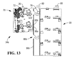
- FIGS 7 to 13 are schematic side views illustrating the picking assembly 34a and the frame 30 at various stages of the coupling process.
- a service engineer (or other authorized person) lifts the picking assembly 34a towards the frame 30 (as illustrated in Fig 7 ) until the mushroom studs 78 abut the upper flanges 96a (as illustrated in Fig 8 ).
- the service engineer then lifts the picking assembly 34a (while maintaining the mushroom studs 78 in contact with the upper flanges 96a) until the mushroom studs 78 are near to the entrance walls 88a of the frame 30, and then pivots the picking assembly 34a about the mushroom studs 78 until a lower portion of the guide edges 60a,b of the picking assembly 34a contact the upper flanges 96a (as illustrated in Fig 9 ).
- the upper flanges 96a operate as a detent to prevent the picking assembly 34a from entering any further into the frame 30. This position is referred to as the initial alignment position.
- the service engineer lifts the picking assembly 34a until the mushroom studs 78 travel over the entrance walls 88a of the frame 30 (as shown in Fig 10 ).
- the service engineer pushes the picking assembly 34a forwards until the mushroom studs 78 travel over the raised projections 89a and then drop down into the narrow guide passages 90a (as illustrated in Fig 11 ). This is referred to as the engagement position.
- the service engineer can release his/her grip on the picking assembly 34a because the mushroom studs 78 engage with the raised projections 89a and the narrow guide passages 90a, thereby preventing the picking assembly 34a from falling backwards or downwards.
- the picking assembly 34a cannot enter any further into the frame 30.
- the service engineer can leave the picking assembly 34a hanging on the frame 30 and perform some other task, if desired.
- the service engineer When the service engineer decides to complete the coupling between the picking assembly 34a and the frame 30, then the service engineer lifts the lower part of the picking assembly 34a (to pivot the picking assembly 34a upwards about the mushroom studs 78) until the guide edges 60a,b of the picking assembly 34a are flush with the upper flanges 96a. The service engineer then pushes the picking assembly 34a into the frame 30 until the mushroom studs 78 reach the lower stop position 92a (as illustrated in Fig 12 ), which is referred to herein as the pre-engaged position.
- the service engineer then lifts the picking assembly 34a vertically from the pre-engaged position until the mushroom studs 78 travel from the lower stop position 92a to the upper stop position 94a (as illustrated in Fig 13 ).
- This position is referred to herein as the engaged position.
- the toggle latches 36 can be coupled with the presenter latch projections (not shown) to secure the picking assembly 34a in place.
- apertures may be provided in the guide edges 60a,b and the upper flanges 96a, so that the apertures are in registration when the picking assembly 34a is in the engaged position. This allows screws or bolts to be used to further secure the picking assembly 34a to the frame 30.
- the service engineer can then couple any required electrical connections (not shown) to the picking assembly 34a, and can also couple the vacuum feed pipe 33 on the frame 30 to the vacuum pipes 52a,b via the vacuum couplings 56a,b.
- the second picking assembly 34b can be coupled in a similar manner.
- the main differences between coupling the picking assembly 34a and the picking assembly 34b are as follows.
- the toggle latches 36 on the picking assembly 34b will couple to the pick latch projections 38 on the lower part of the picking assembly 34a (instead of coupling to the banknote presenter latch projections (not shown)).
- the coupling gear 72 on the second picking assembly 34b will intermesh with the power take-off gear 76 of the first picking assembly 34a (instead of intermeshing with the transfer gear 22 of the banknote presenter 14).
- the upper picking assembly 34a can be unlatched so that both picking assemblies 34a,b fall to the pre-engaged position (as illustrated in Fig 12 for the upper assembly 34a).
- the service engineer can then unlatch the lower picking assembly 34b from the upper picking assembly 34a and remove the upper picking assembly 34a while leaving the lower picking assembly 34b in place.
- a new upper picking assembly 34a can then be installed to the pre-engaged position (following the process of Figs 7 to 12 ) and then latched to the lower picking assembly 34b.
- the picking assemblies 34a,b are mutually coupled and located at the pre-engaged position. From the pre-engaged position, both picking assemblies 34a,b can be lifted as a single unit into the engaged position ( Fig 13 ) and secured there by the latches 36 on the upper picking assembly 34a.
- this embodiment has the advantage that a service engineer can remove part of a pick unit rather than an entire pick unit. In fact, for a four-high pick unit, the service engineer can remove part of a two-high pick module rather than the entire two-high pick module. Since the portion of the pick module that is removable (the picking assembly 34) contains the electro-mechanical devices, this is the portion that is most likely to need replacing. A service engineer should only rarely have to replace the frame 30.
- This embodiment splits a pick module into a removable picking assembly and a removable frame portion.
- the removable frame portion may be shared by multiple pick modules (that is, the same frame may be used by multiple picking assemblies), as in the above embodiment. This is practical because the frame should only rarely need replacing compared with the picking assemblies.
- the picking assembly may only include one pick arm, one pair of tines, and the like.
- the dispenser may include a one-high, a two-high, a three-high, a five-high, or a six-high pick unit, or any desired number of pick units.
- the dispenser may dispense media items other than banknotes.
- the frame may comprise multiple frame portions, one frame portion for each picking assembly.
- each picking assembly may only include one picking mechanism (or three or more picking mechanisms), rather than the two picking mechanisms per picking assembly described in the above embodiment.
- the presenter may be designed to allow both picking assemblies 34a,b to be coupled simultaneously (by coupling them together first using the toggle latches 36) then by lifting and advancing the combined picking assemblies 34a,b directly into the pre-engaged position, then vertically into the engaged position. Once in the engaged position, the toggle latches 36 on the first (upper) picking mechanism 34a can be secured to the presenter latch projections (not shown).
- the combined picking assemblies 34a,b could be removed as a single unit by unlatching the toggle latches 36 from the presenter latch projections (not shown) (causing the combined picking assemblies 34a,b to drop from the engaged position to the pre-engaged position) and pulling the combined picking assemblies 34a,b out and over the raised projections 89a,b, and then out of the frame 30 completely.
- This has the disadvantage that the service engineer has to bear the weight of the combined picking assemblies 34a,b during the de-coupling process, rather than the weight of just one of the picking assemblies 34a,b.
- the steps of the methods described herein may be carried out in any suitable order, or simultaneously where appropriate.
- the methods described herein may be performed by software in machine readable form on a tangible storage medium or as a propagating signal.
Landscapes
- Engineering & Computer Science (AREA)
- Mechanical Engineering (AREA)
- Sheets, Magazines, And Separation Thereof (AREA)
Claims (13)
- Eine abnehmbare Greifanlage (34a,b) für das abnehmbare Ankoppeln an den Rahmen (30) einer Greifvorrichtung (12), bestehend aus:(i) einer Führungskante (60a,b), die so konfiguriert ist, dass sie an eine Sperre (96a,b) grenzt, definiert durch den Rahmen (30) einer Greifvorrichtung (12), wenn die Greifanlage (34a,b) in eine anfängliche Position der Fluchtung im Hinblick auf den Rahmen (30) gebracht wird,gekennzeichnet durch:(ii) eine Kurvenrolle (78), die so konfiguriert ist, dass sie mit einer gewundenen Bahn fluchtet (86a,b), definiert durch den Rahmen (30), wenn die demontierbare Greifanlage (34a,b) von der anfänglichen Position der Fluchtung in eine Position der Einrastung im Hinblick auf den Rahmen (30) gebracht wird, und(iii) ein Räderwerk (70), das so konfiguriert ist, dass es mit einem oberen, gegenüber der Greifvorrichtung (12) externen Getriebe ineinandergreift, wenn die demontierbare Greifanlage (34a,b) in eine einrastende Position bewegt wird, an der die Kurvenrolle (78) das Ende einer gewundenen Bahn (86a,b) erreicht hat.
- Eine demontierbare Greifanlage im Einklang mit Anspruch 1, die ferner einen oder mehrere Riegel (36) zur Ankupplung an eine externe Einheit (14) oberhalb der Greifvorrichtung umfasst.
- Eine demontierbare Greifanlage im Einklang mit Anspruch 2, bei der der eine oder die mehreren Riegel (36) aus Überschnapp-Spannverschlüssen bestehen.
- Eine demontierbare Greifanlage im Einklang mit einem jeglichen vorherigen Anspruch, in der die Kurvenrolle (78) einen pilzförmigen Bolzen umfasst.
- Eine demontierbare Greifanlage im Einklang mit einem jeglichen vorherigen Anspruch, die weiterhin einen Vakuum-Greifarm (50a,b), eine Vakuumleitung (52a,b) in fließender Kommunikation mit dem Vakuum-Greifarm (50a,b) und eine Vakuum-Kupplung (56a,b) für den Anschluss des Vakuumrohrs (52a,b) an ein Rahmenrohr (33) der Greifvorrichtung (12) beinhaltet.
- Eine demontierbare Greifanlage im Einklang mit Anspruch 5, die ferner eine Vielzahl von Vakuum-Greifarmen (50a,b) umfasst.
- Eine Greifvorrichtung (12) bestehend aus:einem Rahmen (30), der einander gegenüberliegende Seitenwände (31 a,b) enthält und folgendes definiert: (i) eine oder mehrere Führungen (64a,b) für den Empfang einer Umlaufkassette, (ii) eine gewundene Bahn (86a,b) zwecks Führung und Unterstützung einer Kurvenrolle (78), und eine Sperre (96a,b); undeine demontierbare Greifanlage (34a,b) im Einklang mit jedem vorstehenden Anspruch zwecks demontierbarer Kupplung an den Rahmen (30) der Greifvorrichtung (12).
- Die Greifvorrichtung im Einklang mit Anspruch 7, in der eine gewundene Bahn (86a,b) konfiguriert ist, um das Räderwerk (70) der demontierbaren Greifanlage (34a,b) unter das obere Getriebe und dann aufwärts zum Einrasten in das obere Getriebe zu bewegen.
- Die Greifvorrichtung im Einklang mit Anspruch 7 oder 8, in der eine gewundene Bahn (86a,b) zur Unterstützung der demontierbaren Greifanlage (34a,b) via die Kurvenrolle (78) konfiguriert ist, wobei die demontierbare Greifanlage (34a,b) sich in der eingerasteten Position befindet.
- Die Greifvorrichtung im Einklang mit einem oder mehreren der Ansprüche 7 bis 9, in der die gewundene Bahn (86a,b) die Form eines Hakens aufweist.
- Die Greifvorrichtung im Einklang mit einem oder mehreren der Ansprüche 7 bis 10, wobei der Rahmen (30) weiterhin Öffnungen definiert, die, wenn die abnehmbare Greifanlage (34a,b) in die eingerastete Position bewegt wird, auf Öffnungen in der abnehmbaren Greifanlage (34a,b) ausgerichtet werden und es den mit Gewinde versehenen Halterungen erlauben, die abnehmbare Greifanlage (34a,b) am Rahmen (30) zu befestigen.
- Eine Medienausgabevorrichtung (10), bestehend aus einer Greifvorrichtung (12) im Einklang mit einem oder mehreren der Ansprüche 7 bis 11.
- Ein Selbstbedienungsterminal (Self-Service Terminal - SST), bestehend aus einer Medienausgabevorrichtung (10) im Einklang mit Anspruch 12.
Applications Claiming Priority (1)
| Application Number | Priority Date | Filing Date | Title |
|---|---|---|---|
| US12/946,972 US8430395B2 (en) | 2010-11-16 | 2010-11-16 | Pick unit |
Publications (3)
| Publication Number | Publication Date |
|---|---|
| EP2452902A2 EP2452902A2 (de) | 2012-05-16 |
| EP2452902A3 EP2452902A3 (de) | 2013-11-27 |
| EP2452902B1 true EP2452902B1 (de) | 2014-12-24 |
Family
ID=44719719
Family Applications (1)
| Application Number | Title | Priority Date | Filing Date |
|---|---|---|---|
| EP11183947.8A Active EP2452902B1 (de) | 2010-11-16 | 2011-10-05 | Verbesserte Aufnahmeeinheit |
Country Status (5)
| Country | Link |
|---|---|
| US (1) | US8430395B2 (de) |
| EP (1) | EP2452902B1 (de) |
| JP (1) | JP5808223B2 (de) |
| CN (1) | CN102530595B (de) |
| BR (1) | BRPI1106829B1 (de) |
Families Citing this family (3)
| Publication number | Priority date | Publication date | Assignee | Title |
|---|---|---|---|---|
| CN103035062B (zh) * | 2012-12-11 | 2015-01-14 | 广州广电运通金融电子股份有限公司 | 一种出钞箱 |
| JP6088453B2 (ja) * | 2014-02-21 | 2017-03-01 | 富士通フロンテック株式会社 | 紙幣取扱い装置及び紙幣取扱いシステム |
| TWI709113B (zh) * | 2019-06-25 | 2020-11-01 | 鴻發國際科技股份有限公司 | 紙頁處理設備 |
Family Cites Families (10)
| Publication number | Priority date | Publication date | Assignee | Title |
|---|---|---|---|---|
| JPS55156148A (en) * | 1979-05-25 | 1980-12-04 | Laurel Bank Mach Co Ltd | Automatic delivery machine |
| US5411249A (en) * | 1994-01-10 | 1995-05-02 | Mars Incorporated | Currency validator and cassette transport alignment apparatus |
| JP4038321B2 (ja) * | 2000-02-25 | 2008-01-23 | 株式会社日本コンラックス | 紙幣処理装置 |
| CA2323377C (en) * | 2000-10-17 | 2008-04-22 | Cashcode Company Inc. | Validator with removable power interface |
| AU2002343933B2 (en) * | 2001-09-28 | 2007-10-25 | Japan Cash Machine Co., Ltd. | Paper sheet handling apparatus |
| US6651796B2 (en) * | 2001-12-14 | 2003-11-25 | International Currency Technologies Corporation | Paper currency receiving system mounting arrangement for an automatic vending machine |
| US6851540B2 (en) * | 2001-12-17 | 2005-02-08 | International Currency Technologies Corporation | Paper currency collection detection arrangement for an automatic vending machine |
| US7222712B2 (en) * | 2003-03-24 | 2007-05-29 | Valtech International, Llc | Document validator with locking cassette |
| DE202005008120U1 (de) * | 2005-05-24 | 2005-07-21 | Automatentechnik Baumann Gmbh | Vorrichtung zur Ausgabe flacher bzw. blattförmiger Gegenstände |
| JP5484866B2 (ja) * | 2009-11-16 | 2014-05-07 | 日本金銭機械株式会社 | 紙葉類取扱装置 |
-
2010
- 2010-11-16 US US12/946,972 patent/US8430395B2/en active Active
-
2011
- 2011-10-05 EP EP11183947.8A patent/EP2452902B1/de active Active
- 2011-11-02 JP JP2011241490A patent/JP5808223B2/ja active Active
- 2011-11-03 BR BRPI1106829-9A patent/BRPI1106829B1/pt active IP Right Grant
- 2011-11-14 CN CN201110358852.4A patent/CN102530595B/zh active Active
Also Published As
| Publication number | Publication date |
|---|---|
| EP2452902A2 (de) | 2012-05-16 |
| CN102530595A (zh) | 2012-07-04 |
| US20120119433A1 (en) | 2012-05-17 |
| US8430395B2 (en) | 2013-04-30 |
| CN102530595B (zh) | 2015-02-11 |
| EP2452902A3 (de) | 2013-11-27 |
| BRPI1106829B1 (pt) | 2020-03-10 |
| JP5808223B2 (ja) | 2015-11-10 |
| JP2012108903A (ja) | 2012-06-07 |
| BRPI1106829A2 (pt) | 2013-07-30 |
Similar Documents
| Publication | Publication Date | Title |
|---|---|---|
| CN102654926B (zh) | 纸币出入款装置 | |
| CN104871217B (zh) | 纸页类处理装置 | |
| CN102842173B (zh) | 纸张类处理装置 | |
| CN103168318B (zh) | 纸张类处理装置以及现金自动交易装置 | |
| CN103824376A (zh) | 介质处理装置 | |
| CN103578186A (zh) | 箱补给 | |
| EP2452902B1 (de) | Verbesserte Aufnahmeeinheit | |
| KR20120078770A (ko) | 지폐저장장치 | |
| KR101628204B1 (ko) | 계원용 금융자동화기기 | |
| CN102459045B (zh) | 束搬运装置及纸张类处理装置 | |
| KR102521980B1 (ko) | 금융자동화기기의 보충회수 카세트용 트랜짓 반송로 유닛 고정구조 | |
| WO2014034246A1 (ja) | 紙葉類取扱装置及び紙葉類収納庫 | |
| CN112581679A (zh) | 一种分体式介质存取装置 | |
| US8733530B2 (en) | Item recycling | |
| JP6361112B2 (ja) | 紙葉類取扱装置 | |
| JP4302651B2 (ja) | 小束紙幣処理機 | |
| JP4302652B2 (ja) | 小束紙幣処理機 | |
| JP2006252075A (ja) | 小束紙幣処理機 | |
| JP2005259084A (ja) | 紙葉類取扱装置の構築方法、及び紙葉類カセット | |
| JP2025175891A (ja) | 媒体処理装置 | |
| JP4321513B2 (ja) | 紙幣収納装置および紙幣処理装置 | |
| JP4549892B2 (ja) | 小束紙幣処理機 | |
| JP4606909B2 (ja) | 小束紙幣処理機 | |
| KR20110118986A (ko) | 금융자동화기기의 카세트 | |
| JP4549894B2 (ja) | 小束紙幣処理機 |
Legal Events
| Date | Code | Title | Description |
|---|---|---|---|
| PUAI | Public reference made under article 153(3) epc to a published international application that has entered the european phase |
Free format text: ORIGINAL CODE: 0009012 |
|
| AK | Designated contracting states |
Kind code of ref document: A2 Designated state(s): AL AT BE BG CH CY CZ DE DK EE ES FI FR GB GR HR HU IE IS IT LI LT LU LV MC MK MT NL NO PL PT RO RS SE SI SK SM TR |
|
| AX | Request for extension of the european patent |
Extension state: BA ME |
|
| PUAL | Search report despatched |
Free format text: ORIGINAL CODE: 0009013 |
|
| AK | Designated contracting states |
Kind code of ref document: A3 Designated state(s): AL AT BE BG CH CY CZ DE DK EE ES FI FR GB GR HR HU IE IS IT LI LT LU LV MC MK MT NL NO PL PT RO RS SE SI SK SM TR |
|
| AX | Request for extension of the european patent |
Extension state: BA ME |
|
| RIC1 | Information provided on ipc code assigned before grant |
Ipc: B65H 1/04 20060101AFI20131023BHEP |
|
| 17P | Request for examination filed |
Effective date: 20140527 |
|
| RBV | Designated contracting states (corrected) |
Designated state(s): AL AT BE BG CH CY CZ DE DK EE ES FI FR GB GR HR HU IE IS IT LI LT LU LV MC MK MT NL NO PL PT RO RS SE SI SK SM TR |
|
| GRAP | Despatch of communication of intention to grant a patent |
Free format text: ORIGINAL CODE: EPIDOSNIGR1 |
|
| GRAS | Grant fee paid |
Free format text: ORIGINAL CODE: EPIDOSNIGR3 |
|
| INTG | Intention to grant announced |
Effective date: 20141029 |
|
| GRAA | (expected) grant |
Free format text: ORIGINAL CODE: 0009210 |
|
| AK | Designated contracting states |
Kind code of ref document: B1 Designated state(s): AL AT BE BG CH CY CZ DE DK EE ES FI FR GB GR HR HU IE IS IT LI LT LU LV MC MK MT NL NO PL PT RO RS SE SI SK SM TR |
|
| REG | Reference to a national code |
Ref country code: GB Ref legal event code: FG4D |
|
| REG | Reference to a national code |
Ref country code: CH Ref legal event code: EP |
|
| REG | Reference to a national code |
Ref country code: IE Ref legal event code: FG4D |
|
| REG | Reference to a national code |
Ref country code: AT Ref legal event code: REF Ref document number: 703000 Country of ref document: AT Kind code of ref document: T Effective date: 20150115 |
|
| REG | Reference to a national code |
Ref country code: DE Ref legal event code: R084 Ref document number: 602011012486 Country of ref document: DE |
|
| REG | Reference to a national code |
Ref country code: GB Ref legal event code: 746 Effective date: 20150122 |
|
| REG | Reference to a national code |
Ref country code: DE Ref legal event code: R096 Ref document number: 602011012486 Country of ref document: DE Effective date: 20150219 |
|
| REG | Reference to a national code |
Ref country code: DE Ref legal event code: R084 Ref document number: 602011012486 Country of ref document: DE Effective date: 20150121 |
|
| REG | Reference to a national code |
Ref country code: NL Ref legal event code: VDEP Effective date: 20141224 |
|
| PG25 | Lapsed in a contracting state [announced via postgrant information from national office to epo] |
Ref country code: NO Free format text: LAPSE BECAUSE OF FAILURE TO SUBMIT A TRANSLATION OF THE DESCRIPTION OR TO PAY THE FEE WITHIN THE PRESCRIBED TIME-LIMIT Effective date: 20150324 Ref country code: LT Free format text: LAPSE BECAUSE OF FAILURE TO SUBMIT A TRANSLATION OF THE DESCRIPTION OR TO PAY THE FEE WITHIN THE PRESCRIBED TIME-LIMIT Effective date: 20141224 Ref country code: FI Free format text: LAPSE BECAUSE OF FAILURE TO SUBMIT A TRANSLATION OF THE DESCRIPTION OR TO PAY THE FEE WITHIN THE PRESCRIBED TIME-LIMIT Effective date: 20141224 |
|
| REG | Reference to a national code |
Ref country code: LT Ref legal event code: MG4D |
|
| PG25 | Lapsed in a contracting state [announced via postgrant information from national office to epo] |
Ref country code: HR Free format text: LAPSE BECAUSE OF FAILURE TO SUBMIT A TRANSLATION OF THE DESCRIPTION OR TO PAY THE FEE WITHIN THE PRESCRIBED TIME-LIMIT Effective date: 20141224 Ref country code: GR Free format text: LAPSE BECAUSE OF FAILURE TO SUBMIT A TRANSLATION OF THE DESCRIPTION OR TO PAY THE FEE WITHIN THE PRESCRIBED TIME-LIMIT Effective date: 20150325 Ref country code: SE Free format text: LAPSE BECAUSE OF FAILURE TO SUBMIT A TRANSLATION OF THE DESCRIPTION OR TO PAY THE FEE WITHIN THE PRESCRIBED TIME-LIMIT Effective date: 20141224 Ref country code: RS Free format text: LAPSE BECAUSE OF FAILURE TO SUBMIT A TRANSLATION OF THE DESCRIPTION OR TO PAY THE FEE WITHIN THE PRESCRIBED TIME-LIMIT Effective date: 20141224 Ref country code: LV Free format text: LAPSE BECAUSE OF FAILURE TO SUBMIT A TRANSLATION OF THE DESCRIPTION OR TO PAY THE FEE WITHIN THE PRESCRIBED TIME-LIMIT Effective date: 20141224 |
|
| REG | Reference to a national code |
Ref country code: AT Ref legal event code: MK05 Ref document number: 703000 Country of ref document: AT Kind code of ref document: T Effective date: 20141224 |
|
| PG25 | Lapsed in a contracting state [announced via postgrant information from national office to epo] |
Ref country code: NL Free format text: LAPSE BECAUSE OF FAILURE TO SUBMIT A TRANSLATION OF THE DESCRIPTION OR TO PAY THE FEE WITHIN THE PRESCRIBED TIME-LIMIT Effective date: 20141224 |
|
| PG25 | Lapsed in a contracting state [announced via postgrant information from national office to epo] |
Ref country code: SK Free format text: LAPSE BECAUSE OF FAILURE TO SUBMIT A TRANSLATION OF THE DESCRIPTION OR TO PAY THE FEE WITHIN THE PRESCRIBED TIME-LIMIT Effective date: 20141224 Ref country code: CZ Free format text: LAPSE BECAUSE OF FAILURE TO SUBMIT A TRANSLATION OF THE DESCRIPTION OR TO PAY THE FEE WITHIN THE PRESCRIBED TIME-LIMIT Effective date: 20141224 Ref country code: EE Free format text: LAPSE BECAUSE OF FAILURE TO SUBMIT A TRANSLATION OF THE DESCRIPTION OR TO PAY THE FEE WITHIN THE PRESCRIBED TIME-LIMIT Effective date: 20141224 Ref country code: ES Free format text: LAPSE BECAUSE OF FAILURE TO SUBMIT A TRANSLATION OF THE DESCRIPTION OR TO PAY THE FEE WITHIN THE PRESCRIBED TIME-LIMIT Effective date: 20141224 Ref country code: RO Free format text: LAPSE BECAUSE OF FAILURE TO SUBMIT A TRANSLATION OF THE DESCRIPTION OR TO PAY THE FEE WITHIN THE PRESCRIBED TIME-LIMIT Effective date: 20141224 |
|
| PG25 | Lapsed in a contracting state [announced via postgrant information from national office to epo] |
Ref country code: IS Free format text: LAPSE BECAUSE OF FAILURE TO SUBMIT A TRANSLATION OF THE DESCRIPTION OR TO PAY THE FEE WITHIN THE PRESCRIBED TIME-LIMIT Effective date: 20150424 Ref country code: AT Free format text: LAPSE BECAUSE OF FAILURE TO SUBMIT A TRANSLATION OF THE DESCRIPTION OR TO PAY THE FEE WITHIN THE PRESCRIBED TIME-LIMIT Effective date: 20141224 Ref country code: PL Free format text: LAPSE BECAUSE OF FAILURE TO SUBMIT A TRANSLATION OF THE DESCRIPTION OR TO PAY THE FEE WITHIN THE PRESCRIBED TIME-LIMIT Effective date: 20141224 |
|
| REG | Reference to a national code |
Ref country code: DE Ref legal event code: R097 Ref document number: 602011012486 Country of ref document: DE |
|
| REG | Reference to a national code |
Ref country code: FR Ref legal event code: PLFP Year of fee payment: 5 |
|
| PG25 | Lapsed in a contracting state [announced via postgrant information from national office to epo] |
Ref country code: DK Free format text: LAPSE BECAUSE OF FAILURE TO SUBMIT A TRANSLATION OF THE DESCRIPTION OR TO PAY THE FEE WITHIN THE PRESCRIBED TIME-LIMIT Effective date: 20141224 |
|
| PLBE | No opposition filed within time limit |
Free format text: ORIGINAL CODE: 0009261 |
|
| STAA | Information on the status of an ep patent application or granted ep patent |
Free format text: STATUS: NO OPPOSITION FILED WITHIN TIME LIMIT |
|
| 26N | No opposition filed |
Effective date: 20150925 |
|
| PG25 | Lapsed in a contracting state [announced via postgrant information from national office to epo] |
Ref country code: IT Free format text: LAPSE BECAUSE OF FAILURE TO SUBMIT A TRANSLATION OF THE DESCRIPTION OR TO PAY THE FEE WITHIN THE PRESCRIBED TIME-LIMIT Effective date: 20141224 |
|
| PG25 | Lapsed in a contracting state [announced via postgrant information from national office to epo] |
Ref country code: SI Free format text: LAPSE BECAUSE OF FAILURE TO SUBMIT A TRANSLATION OF THE DESCRIPTION OR TO PAY THE FEE WITHIN THE PRESCRIBED TIME-LIMIT Effective date: 20141224 |
|
| PG25 | Lapsed in a contracting state [announced via postgrant information from national office to epo] |
Ref country code: LU Free format text: LAPSE BECAUSE OF FAILURE TO SUBMIT A TRANSLATION OF THE DESCRIPTION OR TO PAY THE FEE WITHIN THE PRESCRIBED TIME-LIMIT Effective date: 20151005 Ref country code: BE Free format text: LAPSE BECAUSE OF FAILURE TO SUBMIT A TRANSLATION OF THE DESCRIPTION OR TO PAY THE FEE WITHIN THE PRESCRIBED TIME-LIMIT Effective date: 20141224 |
|
| REG | Reference to a national code |
Ref country code: CH Ref legal event code: PL |
|
| PG25 | Lapsed in a contracting state [announced via postgrant information from national office to epo] |
Ref country code: MC Free format text: LAPSE BECAUSE OF FAILURE TO SUBMIT A TRANSLATION OF THE DESCRIPTION OR TO PAY THE FEE WITHIN THE PRESCRIBED TIME-LIMIT Effective date: 20141224 |
|
| REG | Reference to a national code |
Ref country code: IE Ref legal event code: MM4A |
|
| PG25 | Lapsed in a contracting state [announced via postgrant information from national office to epo] |
Ref country code: LI Free format text: LAPSE BECAUSE OF NON-PAYMENT OF DUE FEES Effective date: 20151031 Ref country code: CH Free format text: LAPSE BECAUSE OF NON-PAYMENT OF DUE FEES Effective date: 20151031 |
|
| REG | Reference to a national code |
Ref country code: FR Ref legal event code: PLFP Year of fee payment: 6 |
|
| PG25 | Lapsed in a contracting state [announced via postgrant information from national office to epo] |
Ref country code: IE Free format text: LAPSE BECAUSE OF NON-PAYMENT OF DUE FEES Effective date: 20151005 |
|
| PG25 | Lapsed in a contracting state [announced via postgrant information from national office to epo] |
Ref country code: SM Free format text: LAPSE BECAUSE OF FAILURE TO SUBMIT A TRANSLATION OF THE DESCRIPTION OR TO PAY THE FEE WITHIN THE PRESCRIBED TIME-LIMIT Effective date: 20141224 Ref country code: HU Free format text: LAPSE BECAUSE OF FAILURE TO SUBMIT A TRANSLATION OF THE DESCRIPTION OR TO PAY THE FEE WITHIN THE PRESCRIBED TIME-LIMIT; INVALID AB INITIO Effective date: 20111005 Ref country code: BG Free format text: LAPSE BECAUSE OF FAILURE TO SUBMIT A TRANSLATION OF THE DESCRIPTION OR TO PAY THE FEE WITHIN THE PRESCRIBED TIME-LIMIT Effective date: 20141224 |
|
| PG25 | Lapsed in a contracting state [announced via postgrant information from national office to epo] |
Ref country code: CY Free format text: LAPSE BECAUSE OF FAILURE TO SUBMIT A TRANSLATION OF THE DESCRIPTION OR TO PAY THE FEE WITHIN THE PRESCRIBED TIME-LIMIT Effective date: 20141224 |
|
| PG25 | Lapsed in a contracting state [announced via postgrant information from national office to epo] |
Ref country code: MT Free format text: LAPSE BECAUSE OF FAILURE TO SUBMIT A TRANSLATION OF THE DESCRIPTION OR TO PAY THE FEE WITHIN THE PRESCRIBED TIME-LIMIT Effective date: 20141224 Ref country code: TR Free format text: LAPSE BECAUSE OF FAILURE TO SUBMIT A TRANSLATION OF THE DESCRIPTION OR TO PAY THE FEE WITHIN THE PRESCRIBED TIME-LIMIT Effective date: 20141224 |
|
| REG | Reference to a national code |
Ref country code: FR Ref legal event code: PLFP Year of fee payment: 7 |
|
| PG25 | Lapsed in a contracting state [announced via postgrant information from national office to epo] |
Ref country code: MK Free format text: LAPSE BECAUSE OF FAILURE TO SUBMIT A TRANSLATION OF THE DESCRIPTION OR TO PAY THE FEE WITHIN THE PRESCRIBED TIME-LIMIT Effective date: 20141224 |
|
| PG25 | Lapsed in a contracting state [announced via postgrant information from national office to epo] |
Ref country code: PT Free format text: LAPSE BECAUSE OF FAILURE TO SUBMIT A TRANSLATION OF THE DESCRIPTION OR TO PAY THE FEE WITHIN THE PRESCRIBED TIME-LIMIT Effective date: 20141224 |
|
| REG | Reference to a national code |
Ref country code: FR Ref legal event code: PLFP Year of fee payment: 8 |
|
| PG25 | Lapsed in a contracting state [announced via postgrant information from national office to epo] |
Ref country code: AL Free format text: LAPSE BECAUSE OF FAILURE TO SUBMIT A TRANSLATION OF THE DESCRIPTION OR TO PAY THE FEE WITHIN THE PRESCRIBED TIME-LIMIT Effective date: 20141224 |
|
| REG | Reference to a national code |
Ref country code: DE Ref legal event code: R081 Ref document number: 602011012486 Country of ref document: DE Owner name: CARDTRONICS USA, INC. (GESELLSCHAFT NACH DEN G, US Free format text: FORMER OWNER: NCR CORPORATION, DULUTH, GA., US Ref country code: DE Ref legal event code: R082 Ref document number: 602011012486 Country of ref document: DE Representative=s name: V. BEZOLD & PARTNER PATENTANWAELTE - PARTG MBB, DE Ref country code: DE Ref legal event code: R081 Ref document number: 602011012486 Country of ref document: DE Owner name: NCR CORPORATION, ATLANTA, US Free format text: FORMER OWNER: NCR CORPORATION, DULUTH, GA., US |
|
| P01 | Opt-out of the competence of the unified patent court (upc) registered |
Effective date: 20230507 |
|
| REG | Reference to a national code |
Ref country code: DE Ref legal event code: R081 Ref document number: 602011012486 Country of ref document: DE Owner name: CARDTRONICS USA, INC. (GESELLSCHAFT NACH DEN G, US Free format text: FORMER OWNER: NCR CORPORATION, ATLANTA, GA, US |
|
| PGFP | Annual fee paid to national office [announced via postgrant information from national office to epo] |
Ref country code: DE Payment date: 20251029 Year of fee payment: 15 |
|
| PGFP | Annual fee paid to national office [announced via postgrant information from national office to epo] |
Ref country code: GB Payment date: 20251027 Year of fee payment: 15 |
|
| PGFP | Annual fee paid to national office [announced via postgrant information from national office to epo] |
Ref country code: FR Payment date: 20251027 Year of fee payment: 15 |