EP2452160B1 - Capteur de position absolue et multi-périodique - Google Patents
Capteur de position absolue et multi-périodique Download PDFInfo
- Publication number
- EP2452160B1 EP2452160B1 EP10742215.6A EP10742215A EP2452160B1 EP 2452160 B1 EP2452160 B1 EP 2452160B1 EP 10742215 A EP10742215 A EP 10742215A EP 2452160 B1 EP2452160 B1 EP 2452160B1
- Authority
- EP
- European Patent Office
- Prior art keywords
- magnetised
- unit
- magnetic
- probe
- sensor
- Prior art date
- Legal status (The legal status is an assumption and is not a legal conclusion. Google has not performed a legal analysis and makes no representation as to the accuracy of the status listed.)
- Active
Links
- 239000000523 sample Substances 0.000 claims description 90
- 230000005291 magnetic effect Effects 0.000 claims description 75
- 238000001514 detection method Methods 0.000 claims description 9
- 230000033001 locomotion Effects 0.000 claims description 8
- 230000004907 flux Effects 0.000 claims description 3
- 230000005415 magnetization Effects 0.000 description 26
- 238000005259 measurement Methods 0.000 description 18
- 230000006870 function Effects 0.000 description 12
- 238000006073 displacement reaction Methods 0.000 description 10
- 230000005405 multipole Effects 0.000 description 7
- 230000000737 periodic effect Effects 0.000 description 7
- 230000009467 reduction Effects 0.000 description 5
- 230000008901 benefit Effects 0.000 description 4
- 238000004146 energy storage Methods 0.000 description 4
- 230000001965 increasing effect Effects 0.000 description 4
- 230000005381 magnetic domain Effects 0.000 description 4
- 230000010363 phase shift Effects 0.000 description 4
- 238000004364 calculation method Methods 0.000 description 3
- 238000013016 damping Methods 0.000 description 3
- PCHJSUWPFVWCPO-UHFFFAOYSA-N gold Chemical compound [Au] PCHJSUWPFVWCPO-UHFFFAOYSA-N 0.000 description 3
- 239000010931 gold Substances 0.000 description 3
- 229910052737 gold Inorganic materials 0.000 description 3
- 238000010606 normalization Methods 0.000 description 3
- 238000012545 processing Methods 0.000 description 3
- 238000004891 communication Methods 0.000 description 2
- 230000007423 decrease Effects 0.000 description 2
- 238000011161 development Methods 0.000 description 2
- 230000018109 developmental process Effects 0.000 description 2
- 238000005516 engineering process Methods 0.000 description 2
- 230000005294 ferromagnetic effect Effects 0.000 description 2
- 230000006698 induction Effects 0.000 description 2
- 230000001939 inductive effect Effects 0.000 description 2
- 230000003993 interaction Effects 0.000 description 2
- 230000003287 optical effect Effects 0.000 description 2
- 230000000704 physical effect Effects 0.000 description 2
- 230000005355 Hall effect Effects 0.000 description 1
- 240000008042 Zea mays Species 0.000 description 1
- 230000001174 ascending effect Effects 0.000 description 1
- 239000003638 chemical reducing agent Substances 0.000 description 1
- 238000010276 construction Methods 0.000 description 1
- 230000008878 coupling Effects 0.000 description 1
- 238000010168 coupling process Methods 0.000 description 1
- 238000005859 coupling reaction Methods 0.000 description 1
- 230000001419 dependent effect Effects 0.000 description 1
- 230000001627 detrimental effect Effects 0.000 description 1
- 239000000428 dust Substances 0.000 description 1
- 230000000694 effects Effects 0.000 description 1
- 230000007613 environmental effect Effects 0.000 description 1
- 238000011156 evaluation Methods 0.000 description 1
- 230000005284 excitation Effects 0.000 description 1
- 238000003780 insertion Methods 0.000 description 1
- 230000037431 insertion Effects 0.000 description 1
- 239000007788 liquid Substances 0.000 description 1
- 238000000034 method Methods 0.000 description 1
- 230000004048 modification Effects 0.000 description 1
- 238000012986 modification Methods 0.000 description 1
- 238000011176 pooling Methods 0.000 description 1
- 230000003252 repetitive effect Effects 0.000 description 1
- 238000005070 sampling Methods 0.000 description 1
- 239000004065 semiconductor Substances 0.000 description 1
- 239000007787 solid Substances 0.000 description 1
- 230000007704 transition Effects 0.000 description 1
Images


Classifications
-
- B—PERFORMING OPERATIONS; TRANSPORTING
- B62—LAND VEHICLES FOR TRAVELLING OTHERWISE THAN ON RAILS
- B62D—MOTOR VEHICLES; TRAILERS
- B62D15/00—Steering not otherwise provided for
- B62D15/02—Steering position indicators ; Steering position determination; Steering aids
- B62D15/021—Determination of steering angle
- B62D15/0215—Determination of steering angle by measuring on the steering column
-
- B—PERFORMING OPERATIONS; TRANSPORTING
- B62—LAND VEHICLES FOR TRAVELLING OTHERWISE THAN ON RAILS
- B62D—MOTOR VEHICLES; TRAILERS
- B62D15/00—Steering not otherwise provided for
- B62D15/02—Steering position indicators ; Steering position determination; Steering aids
- B62D15/021—Determination of steering angle
- B62D15/0245—Means or methods for determination of the central position of the steering system, e.g. straight ahead position
-
- B—PERFORMING OPERATIONS; TRANSPORTING
- B62—LAND VEHICLES FOR TRAVELLING OTHERWISE THAN ON RAILS
- B62D—MOTOR VEHICLES; TRAILERS
- B62D6/00—Arrangements for automatically controlling steering depending on driving conditions sensed and responded to, e.g. control circuits
- B62D6/08—Arrangements for automatically controlling steering depending on driving conditions sensed and responded to, e.g. control circuits responsive only to driver input torque
- B62D6/10—Arrangements for automatically controlling steering depending on driving conditions sensed and responded to, e.g. control circuits responsive only to driver input torque characterised by means for sensing or determining torque
-
- G—PHYSICS
- G01—MEASURING; TESTING
- G01B—MEASURING LENGTH, THICKNESS OR SIMILAR LINEAR DIMENSIONS; MEASURING ANGLES; MEASURING AREAS; MEASURING IRREGULARITIES OF SURFACES OR CONTOURS
- G01B7/00—Measuring arrangements characterised by the use of electric or magnetic techniques
- G01B7/30—Measuring arrangements characterised by the use of electric or magnetic techniques for measuring angles or tapers; for testing the alignment of axes
-
- G—PHYSICS
- G01—MEASURING; TESTING
- G01D—MEASURING NOT SPECIALLY ADAPTED FOR A SPECIFIC VARIABLE; ARRANGEMENTS FOR MEASURING TWO OR MORE VARIABLES NOT COVERED IN A SINGLE OTHER SUBCLASS; TARIFF METERING APPARATUS; MEASURING OR TESTING NOT OTHERWISE PROVIDED FOR
- G01D5/00—Mechanical means for transferring the output of a sensing member; Means for converting the output of a sensing member to another variable where the form or nature of the sensing member does not constrain the means for converting; Transducers not specially adapted for a specific variable
- G01D5/12—Mechanical means for transferring the output of a sensing member; Means for converting the output of a sensing member to another variable where the form or nature of the sensing member does not constrain the means for converting; Transducers not specially adapted for a specific variable using electric or magnetic means
- G01D5/244—Mechanical means for transferring the output of a sensing member; Means for converting the output of a sensing member to another variable where the form or nature of the sensing member does not constrain the means for converting; Transducers not specially adapted for a specific variable using electric or magnetic means influencing characteristics of pulses or pulse trains; generating pulses or pulse trains
- G01D5/249—Mechanical means for transferring the output of a sensing member; Means for converting the output of a sensing member to another variable where the form or nature of the sensing member does not constrain the means for converting; Transducers not specially adapted for a specific variable using electric or magnetic means influencing characteristics of pulses or pulse trains; generating pulses or pulse trains using pulse code
- G01D5/2492—Pulse stream
-
- G—PHYSICS
- G01—MEASURING; TESTING
- G01D—MEASURING NOT SPECIALLY ADAPTED FOR A SPECIFIC VARIABLE; ARRANGEMENTS FOR MEASURING TWO OR MORE VARIABLES NOT COVERED IN A SINGLE OTHER SUBCLASS; TARIFF METERING APPARATUS; MEASURING OR TESTING NOT OTHERWISE PROVIDED FOR
- G01D2205/00—Indexing scheme relating to details of means for transferring or converting the output of a sensing member
- G01D2205/20—Detecting rotary movement
- G01D2205/26—Details of encoders or position sensors specially adapted to detect rotation beyond a full turn of 360°, e.g. multi-rotation
Definitions
- the present invention relates to the field of magnetic position sensors comprising at least one permanent magnet.
- the present invention relates to the field of linear or rotary position sensors for angles greater than about ten degrees and up to several turns.
- a particularly interesting use lies in position sensors for measuring the angular position of a steering column for automobiles, without this application being exclusive.
- the invention also relates to the field of magnetic devices for detecting a torque between a first shaft and a second shaft connected by a torsion bar, in particular intended for an automobile steering column,
- the angular position of the steering column and the steering wheel is a necessary information for functions such as the electronic stability control of the vehicle (in English ESP: Electronic Stability Program) and the electric power steering (EPS: Electric Power Steering).
- the information of the steering angle, and therefore the wheels, can also be used for additional functions such as directional lights, trajectory control, automatic parking etc.
- a monotour sensor alone can not detect the position of the column of the majority of automobiles whose steering wheel must be able to turn by more than one revolution.
- One solution may be to associate a 360 ° sensor with a "top tour" to find out which turn the steering wheel is in. This is for example described in the application WO07014599 or EP1167927 . These systems assume an initial position when powering on. All subsequent positions are relative to this starting position. The problem posed by this type of system is that this initial position is redefined each time the contact of the automobile is established. If this system does not have a memory of the last position of the steering wheel angle or if the angle is changed when the ignition is off, the angle indicated at the ignition will be wrong.
- the information on the magnetic field intensity emitted by the first sensor is generated by the voltage information in the measurement unit.
- the maximum value of this information is recorded to mark a certain angle of rotation.
- the information on the magnetic field intensity emitted by the second sensor is generated by amplified voltage information in the measurement unit.
- the voltage measurement unit When the voltage information of the first sensor passes the maximum voltage point (Ux) and when the amplified voltage information of the second sensor exceeds (Ux), the voltage measurement unit reverses the digit of the first sensor 180 DEG around the voltage axis (ux) for producing a voltage signal in ascending order by a complete revolution in the first direction.
- the rotation of each magnet is detected by a magnetosensitive probe and the phase-shifted signals are processed by an algorithm.
- the accuracy of the absolute angle measured therefore depends on the difference of two signals from two different sensors and also the algorithm Calculation.
- the subtraction of two signals to obtain a single measurement is a big drawback. This reduces the accuracy by two compared to the accuracy of one of the two sensors alone.
- the slightest error of one of the two sensors, the slightest mechanical phase shift, the slightest play in one of the gears causes an error in the measurement of the angle.
- this requires a very elaborate algorithm to calculate the absolute angle of the rotary member.
- the use of mechanical gearboxes is not an entirely non-contact solution and therefore adds friction in the system (the gear gears are wear parts and therefore limit the service life).
- the addition of these gears and the complexity of assembly of the complete sensor makes the whole expensive and does not allow to have a limited space.
- the accuracy of the sensor is determined by the accuracy of the sensor which measures the absolute angle of rotation of the rotary member, accuracy limited to +/- 2deg, which is insufficient for applications for automotive steering columns. But above all this solution also uses a mechanical gear system with the disadvantages mentioned above.
- the patent DE102007039051 which describes a tachometer technology, based on the use of a Wiegandt wire. Whenever a magnetic transition passes the wire, the sudden orientation of the magnetic domains of the wire induces a voltage in the encircling coil, which voltage is used by a counting unit to increment a number of turns and store it. in a non-volatile memory.
- this method is dependent on a set of Wiegand wire (detection of the passage of the magnets) + coil (detection of the magnetic modification in the wire) + counting unit (which sends the information of a detected lathe) + memory no volatile (which stores the number of laps made) and therefore requires a lot of elements to work.
- the senor can be realized at the end of an axis without any possibility given as to a embodiment with traversing axis.
- the sensor must be supplied with current so that the auxiliary probes determine the direction of rotation.
- the patent is also known WO9911999 describing an apparatus for measuring a rotational movement in which the device for sampling the rotation of the workpiece to be measured comprises a part which generates a magnetic field, and a part placed in the magnetic field mentioned, which has at least the first and the second calibration sensor the field strength so that the parts are rotated relative to each other when the workpiece to be measured rotates
- the German patent DE102007039051 describes a high resolution absolute position sensor, comprising: a shaft, at least one movable excitation magnet fixed to said shaft; a Wiegand effect element comprises a ferromagnetic element, a rotation counter, said counter rotation unit having a nonvolatile data memory.
- a first sensor comprises an induction coil wound around said ferromagnetic coil, said induction coil provides a first output, said first output provides an output current, a second sensor, said second sensor provides a second output;
- a control logic device for processing said first output signal from said first sensor and said second output signal from said second sensor; an energy storage circuit; a power controller in electrical communication with said first output of said first sensor, said second sensor, said counter, and said energy storage circuit; said operating power controller without external electrical energy, said energy storage circuit receiving energy from said first sensor;
- a [mu] -controller for analyzing the fine resolution information from said third output of said third detector, said [mu] controller in electrical communication with said logic device; control, and said power controller, at least one of said Wiegand element, said first sensor, said second sensor, said third sensor, said control logic device, said energy storage circuit, said power controller, counter said counter having a nonvolatile data memory unit, said third sensor for fine resolution of a revolution, said storage circuit energy, and said [mu] -controller, is integrated into an integrated circuit in a storage medium. chip / semiconductor, and said counter determines the number of turns and the position of said shaft.
- the patent EP1203932 discloses a sensor coupled to an evaluation circuit for processing simultaneous signals provided by the sensors to indicate the rotational position of a rotational member with respect to a reference position.
- a power supply system provides energy pulses for the sensing device at a repetitive rate sufficient to detect the direction of rotation of the sensing element. rotation of the detected angle range between successive pulses of energy.
- German patent DE102006032266 discloses a device comprising a sensor assembly comprising at least one sensor element; an additional sensor assembly comprising at least one additional sensor element; a switch in the coupling element the additional sensor assembly to the signal switch responsive sensor assembly for providing a global sensor assembly including reduced power demand.
- the present invention proposes to respond to the problems posed by the prior art by providing a non-contact position sensor having increased reliability and precision.
- the invention proposes a magnetic position sensor, comprising at least one magnetized unit, a first magnetosensitive probe and a second magnetosensitive probe; the first and second magnetosensitive probes being fixed relative to each other; the magnetized unit being movable with respect to these first and second magnetosensitive probes on a displacement stroke and presenting at each instant an absolute position; said magnetized unit producing in the vicinity of said first magnetosensitive probe a magnetic field having a normal component on the one hand, and at least one tangential or transverse component on the other hand, varying sinusoidally and periodically over N periods distributed over the race of displacement, N being a number greater than 1; said first magnetosensitive probe being able to measure at least two of the three components of the magnetic field so as to determine a first datum relating to the position of the magnetized unit.
- the second magnetosensitive probe is able to measure absolutely, incrementally and reversibly a number of complete rotations of the magnetic field so as to determine a second data relating to the position of the magnetized unit, whether this second magnetosensitive probe is powered or not and the sensor comprising a module for calculating the absolute position of the magnetized unit from the first and second data.
- a first magnetosensitive probe measures two of the three components (or measures the angle directly) of the magnetic field generated by the magnetized unit (1) and decodes the position of the magnetic unit to from these two components whose amplitudes are generally different, requiring to normalize the two components used to be able to calculate the tangent arc to deduce the position.
- These tangent arc and normalization functions are carried out either by a separate element or directly by a probe (for example: MELEXIS 90316, HAL 3625) integrating the measurement of the two components of the field, the tangent arc calculation and the normalization of two components of the field.
- a second magnetosensitive probe is then used to discriminate the period in which one finds oneself and thus to determine in an absolute way the position of the magnetized unit relative to the probes.
- the output signal being repeated n times on the desired course, we can not, just with the first signal from the first probe, deduce the position of the magnetized unit, which is why this invention is proposed to add, a second probe that defines in which linear portion is found from the same magnet that generates the magnetic field seen by the first probe.
- a component based on the rotation of magnetic moments as described in US Pat. EP1532425B1 and EP1740909B1 ).
- the magnetic domains rotate continuously at the same time as the rotation of the magnetic field generated by the magnetized unit in which it is located but propagate within a magnetic circuit only at each rotation of the magnetic field to obtain, in the final and at the output processing, a signal that increments or decrements discretely but absolutely every 360 degrees of rotation of the magnetic field. This makes it possible to discriminate absolutely the period inside which one is. Moreover, since such a component is based on the rotation of the magnetic domains, even when the probe is unpowered and there is a displacement between the magnet and this second magnetosensitive probe, called ASIC, the magnetic domains rotate and propagate more or less depending on this displacement. Once the electrical contact is established, no position was lost. It is commonly said that this system is TPO ("True Power On") and works in both directions of motion without bringing hysteresis.
- the present component used allows, on its own, the measurement and counting of the number by modifying its physical properties (see figure 7 ).
- the assembly made is thus compact and can be offset at the periphery of the magnet in the case where the detection of a traversing shaft is required.
- the solution proposed by the present application makes it possible to obtain a completely non-contact solution and thus to overcome the need for additional mechanical parts and to simplify the sensor, to reduce its cost price while increasing its accuracy.
- This solution thus makes it possible to increase the reliability of the measurements while advantageously adapting it to different geometrical configurations (sensor 2 turns, 3 turns, etc.) and adapting it to the desired precision, in particular in the case of a device with traversing axis.
- the magnetic field In the vicinity of these magnets, the magnetic field generates substantially sinusoidal tangential (Bt), normal (Bn) and transverse (Bz) components of period 2pi / N.
- Bt tangential
- Bn normal
- Bz transverse
- the Bn and Bz components have the same phase, while the Bt component is out of phase by a quarter of a period.
- a first magnetosensitive probe is used which integrates the measurement of two components of the field, the tangent arc calculation and the normalization of the two components of the field if necessary.
- the decoding of the angular position of the magnetized unit from these two components whose amplitudes are in general different requires to standardize the two components used to be able to calculate the tangent arc to deduce the linear position.
- the precision of the linear parts is of the order +/- 0.3% over a period of length 2pi / N.
- the first and second magnetosensitive probes are positioned on one and the same printed circuit.
- This probe (3) can be limited by the number Nr of complete rotations of the field which it can distinguish according to the application. For example, if it is integrated in front of our magnetized unit which has N periods, it will deliver at most Nr values of different increments and thus in the end the sensor will be absolute and very high precision on Nr / N turns. If we thus want an absolute sensor on a given number of rounds, it will be necessary to adjust the number of periods of the magnetization to obtain an absolute sensor on the right number of turns.
- the invention can be envisaged in linear application.
- the magnetized unit then extends linearly in the direction of travel.
- a magnet in the form of a band whose direction of magnetization varies continuously in the direction of displacement.
- a first probe measures the radial, normal and axial components to determine the position of the magnet, within a period.
- a second absolute incremental probe is used to count the number of rotations of the magnetic field emitted by the magnetized unit.
- the magnetized unit has a shape extending over an angular width of less than 360 °. In this way, the position signal obtained by combining the signals of the first and second probes is very accurate.
- the present invention also proposes producing a torque sensor comprising a position sensor as described above.
- the invention proposes a magnetic device for detecting a torque between a first shaft and a second shaft connected by a torsion bar, in particular intended for an automobile steering column, comprising: a position sensor as defined previously; a first rotor magnetic structure integral with the first shaft and comprising a plurality of radially oriented magnets; a second solid stator structure of the second shaft and comprising two extended crowns of oriented teeth axially and nested, and a third fixed collector structure consisting of two flux closure parts which define at least one gap in which is placed at least a third magneto-sensitive probe.
- This construction thus makes it possible to obtain a torque and absolute position multiturn sensor whose axial and radial dimensions are identical to the dimensions of a single torque sensor by adding only one magnet and two probes and reusing all the others. parts of the torque sensor.
- the magnet of the torque sensor and the magnet of the position sensor are concentric and all the hall elements are located in the median plane of the magnets which is perpendicular to the axis of rotation of the sensors. This has the advantage of being able to insert all the hall elements on a single printed circuit and to cancel the magnetic interaction of one sensor on the other.
- the cost of such an integrated sensor is reduced by pooling the parts that compose it:
- the magnet of the position sensor and the concentric rings of the torque sensor can be overmolded at the same time and therefore only form one piece, and the same for the Hall sensors of the torque and position sensor that are part of the same single circuit board.
- one will choose the angular width of the collectors equal or K periodic to the angular width of a period of the magnet of the position sensor.
- This embodiment provides a torque sensor solution and multiturn position judiciously combines the 1st preferred embodiment has a magnetic torque sensor such as that described in patent FR2872896 and using only one common magnet for both sensors. So, this magnet would be the source of the field for the torque sensor and for the position sensor, all the electronic components being placed on the same printed circuit. In this configuration, it is necessary to axially move the stators of the torque sensor so that the first and second probes can measure the field generated by the single magnet. The axial size is greater, but it reduces the cost of the sensor using only one magnet
- the computation of the torque will be done by means of the measurement of the relative angle between the two trees that is to say ( ⁇ 1- ⁇ 2).
- This embodiment therefore makes it possible, by adding to the sensor linked to the input shaft which is defined by the first embodiment, only an identical magnet but linked to the output shaft as well as the same first power sensor. obtain a multiturn torque and position sensor with a minimum number of parts. Indeed, we have more in this configuration need stators and collectors for the torque sensor which were expensive parts.
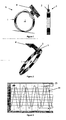
- the figure 1 presents a sensor (A) of mono or multiturn high precision position according to a first embodiment. It consists of a magnet (1) having several magnetization periods. The direction of the magnetization thus varies continuously in the direction of angular displacement of the magnet (1) and is repeated, in this non-limiting example, four times over the 360 ° of the magnet (1).
- a first probe (2) Near the magnet (1) is positioned a first probe (2), said and placed on a printed circuit (4), which measures the direction of the magnetic field generated by the magnet (1) and not its amplitude.
- a printed circuit (4) which measures the direction of the magnetic field generated by the magnet (1) and not its amplitude.
- Hall effect probes such as MLX90316, 2SA10, or magnetoresistive type (AMR, GMR, ). In the vicinity of this magnet, this magnetization generates a magnetic field whose components are substantially sinusoidal.
- the figure 3 shows, as a function of the position -in degree-, the evolution of the amplitude -in volt- of the radial component (23) and the tangential component (24) measured by the probe (2) from a magnet and a magnetization as shown in FIG. figure 1 .
- the signal obtained has a very good linearity over a period of 90 °.
- the typical value is about 0.3%, which corresponds to 0.27 °.
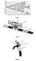
- This absolute incremental probe (3) makes it possible to detect, in an absolute manner, the number of rotations made by the magnetic field of the magnet (1) whether the absolute incremental probe (3) is powered or not with electric current. The detection is thus performed by modifying the physical properties of the absolute incremental probe (3).
- the absolute incremental probe (3) is limited by the number Nr of complete rotation of the field that it can distinguish. For example, if it is integrated in front of a magnet with several Npp magnetization periods, this component will deliver a discrete signal (Nr values) and will be periodic with period Nr / Npp.
- the present invention can be declined in various ways and in particular by using a magnet (1) in the form of a disk as shown in FIG. figure 2 .
- the magnet (1) disk has an alternation of magnetic poles North-South following several periods on the 360 ° of the magnet.
- the direction of magnetization is perpendicular to the surface of the disk.
- the figure 9 shows a rotary variant in the form of an arc or magnet tile (1) which has an alternation of magnetic north-south magnetized poles of radial magnetization, a printed circuit (4) supporting the two probes (2 and 3 ).
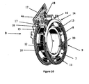
- the present invention is particularly relevant in the context of a combination of the position sensor (A) with a torque sensor (B), as described for example in the patent application. FR2872896 filed by the plaintiff and presented in figure 10 .
- a fourth structure composed of a multipolar magnet magnet (1) with a continuously variable magnetization direction which can be overmoulded on the pastic part (not shown) which supports the second magnetic structure (9) of the torque sensor ( B).
- a printed circuit (4a) supporting the probe (2), the absolute incremental probe (3) necessary for the operation of the position sensor (A) and the third magnetosensitive probe (18) which measures the amplitude field for use of the torque sensor (B).
- the multipole magnet (1) with continuously variable magnetization direction is integral with the stator structure (9).
- This new sensor has the same size as a traditional torque sensor but it also measures the angular position of the shaft (6) which is integral with the stator part (9) and this absolutely and over several turns.
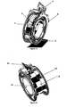
- the figure 12 presents another possible combination of the position sensor (A) with a torque sensor (B) as described above.
- the magnet (8) is multipole with radial magnetization.
- this magnet (1) is the source of the field for the torque sensor (B) and for the position sensor (A), all the probes (2, 3, 18) being placed on the same printed circuit (4a). .
- This has the advantage of having only one magnet (1) with the disadvantage of increasing the axial size.
- FIG. figure 13 where the single magnet (1, 8) is made protruding from the stator assembly (9) to place the probes (2 and 3) on another printed circuit (4b).
- the set allows thus ensuring insensitivity of the position sensor (A) to the torque sensor (B).
- the figure 14 finally presents an innovative torque and position sensor always based on the use of a position sensor (A) as presented in figure 1 .
- two multipolar magnets (1 a and 1 b) with continuously variable magnetization direction are used.
- the present invention proposes to integrate on each shaft (5 and 6) a magnet magnetization direction multipole magnet (respectively 1a and 1b) continuously variable with N pole pairs and 1 magnetosensitive probe (respectively 2a and 2b) which measures the radial (or axial) and tangential components of the magnetic field generated in front of each magnet (1a and 1b) and absolute absolute incremental probe (3) in front of a magnet (1b) connected either to the input shaft ( 5), or to the output shaft (6).
- a magnet magnetization direction multipole magnet (respectively 1a and 1b) continuously variable with N pole pairs and 1 magnetosensitive probe (respectively 2a and 2b) which measures the radial (or axial) and tangential components of the magnetic field generated in front of each magnet (1a and 1b) and absolute absolute incremental probe (3) in front of a magnet (1b) connected either to the input shaft ( 5), or to the output shaft (6).
- the probe (2a) is placed on a first printed circuit (4a) and the probes (2b and 3) are placed on a second printed circuit (4b) as shown in FIG. figure 15 .
Landscapes
- Engineering & Computer Science (AREA)
- Chemical & Material Sciences (AREA)
- Combustion & Propulsion (AREA)
- Transportation (AREA)
- Mechanical Engineering (AREA)
- Physics & Mathematics (AREA)
- General Physics & Mathematics (AREA)
- Measurement Of Length, Angles, Or The Like Using Electric Or Magnetic Means (AREA)
- Transmission And Conversion Of Sensor Element Output (AREA)
- Steering Controls (AREA)
Applications Claiming Priority (2)
| Application Number | Priority Date | Filing Date | Title |
|---|---|---|---|
| FR0903349A FR2947902B1 (fr) | 2009-07-07 | 2009-07-07 | Capteur de position absolue et multi-periodique |
| PCT/FR2010/051431 WO2011004120A2 (fr) | 2009-07-07 | 2010-07-07 | Capteur de position absolue et multi-périodique |
Publications (2)
| Publication Number | Publication Date |
|---|---|
| EP2452160A2 EP2452160A2 (fr) | 2012-05-16 |
| EP2452160B1 true EP2452160B1 (fr) | 2015-10-28 |
Family
ID=42115511
Family Applications (1)
| Application Number | Title | Priority Date | Filing Date |
|---|---|---|---|
| EP10742215.6A Active EP2452160B1 (fr) | 2009-07-07 | 2010-07-07 | Capteur de position absolue et multi-périodique |
Country Status (8)
| Country | Link |
|---|---|
| US (1) | US8890514B2 (ja) |
| EP (1) | EP2452160B1 (ja) |
| JP (1) | JP5480967B2 (ja) |
| KR (1) | KR101721087B1 (ja) |
| CN (1) | CN102472642B (ja) |
| ES (1) | ES2558059T3 (ja) |
| FR (1) | FR2947902B1 (ja) |
| WO (1) | WO2011004120A2 (ja) |
Families Citing this family (45)
| Publication number | Priority date | Publication date | Assignee | Title |
|---|---|---|---|---|
| DE102011010964A1 (de) * | 2010-02-12 | 2011-08-18 | Marquardt Mechatronik GmbH, 78604 | Verfahren zur Positionsmessung |
| FR2964190B1 (fr) | 2010-08-24 | 2013-02-08 | Moving Magnet Tech | Dispositif de detection magnetique de position absolue multitour |
| FR2965347B1 (fr) | 2010-09-29 | 2015-04-03 | Moving Magnet Tech | Capteur de position ameliore |
| JP5789895B2 (ja) * | 2011-08-05 | 2015-10-07 | 株式会社タムロン | 位置検出ユニット、及びそれを備えたレンズユニット、カメラ、及びレンズユニットの製造方法、位置検出方法 |
| USRE47564E1 (en) * | 2012-04-26 | 2019-08-06 | Denso Corporation | Motor |
| JP5675700B2 (ja) * | 2012-05-25 | 2015-02-25 | 株式会社日本自動車部品総合研究所 | トルクセンサ |
| US20130335072A1 (en) * | 2012-06-15 | 2013-12-19 | Wolfram Malzfeldt | Steering torque angle sensor having a processor and a magneto-resistive element configured in a monolithic architecture |
| DE102013006379A1 (de) * | 2013-04-13 | 2014-10-16 | Valeo Schalter Und Sensoren Gmbh | Sensorvorrichtung mit einer Drehmomentsensoreinrichtung und einer Inkrementalsensoreinrichtung und Kraftfahrzeug |
| US9803997B2 (en) * | 2013-07-26 | 2017-10-31 | Bei Sensors & Systems Company, Inc. | System and method for determining absolute angular position of a rotating member |
| US9389283B2 (en) * | 2013-07-26 | 2016-07-12 | Sensata Technologies, Inc. | System and method for converting output of sensors to absolute angular position of a rotating member |
| DE102013114825B4 (de) * | 2013-12-23 | 2023-09-28 | Tdk-Micronas Gmbh | Vorrichtung zur Messung eines Winkels einer Drehachse |
| FR3018966A1 (fr) | 2014-03-21 | 2015-09-25 | Mmt Sa | Machine electrique hybride |
| CN104634367B (zh) * | 2015-03-04 | 2017-06-13 | 哈尔滨工业大学 | 一种大中心孔结构的磁电式绝对位置传感器及测量绝对位置的方法 |
| US10794780B2 (en) * | 2015-10-08 | 2020-10-06 | Steering Solutions Ip Holding Corporation | Magnetic support structure of a torque sensor assembly including a central hub and a plurality of spoke segments extending radially outwardly from the central hub |
| US11448524B2 (en) | 2016-04-07 | 2022-09-20 | Phoenix America Inc. | Multipole magnet for use with a pitched magnetic sensor |
| US20190178683A1 (en) * | 2016-05-17 | 2019-06-13 | Kongsberg Inc. | System, Method And Object For High Accuracy Magnetic Position Sensing |
| DE102016212925A1 (de) * | 2016-07-14 | 2018-01-18 | Schaeffler Technologies AG & Co. KG | Permanentmagnet für eine Sensoranordnung zur Bestimmung einer Winkelposition des Permanentmagneten |
| CN109642808A (zh) * | 2016-08-05 | 2019-04-16 | 哈姆林电子(苏州)有限公司 | 磁角位置传感器电路 |
| CN110088583B (zh) | 2016-12-12 | 2021-07-30 | 康斯博格股份有限公司 | 双频带磁致弹性扭矩传感器 |
| US10234263B2 (en) * | 2016-12-15 | 2019-03-19 | Mando Corporation | Non-contact angle/torque sensor for steering apparatus of vehicle |
| KR20190109474A (ko) * | 2017-01-25 | 2019-09-25 | 바이오코프 프로덕션 에스.에이. | 주입 가능한-약물 전달 장치들을 위한 투여량 제어 시스템 및 연관된 이용 방법들 |
| FR3064835B1 (fr) | 2017-03-31 | 2020-01-17 | Moving Magnet Technologies | Stator pour machine electrique |
| FR3064837B1 (fr) | 2017-04-03 | 2020-01-17 | Moving Magnet Technologies | Rotor pour machine electrique a aimants permanents internes |
| CN107655399A (zh) * | 2017-07-12 | 2018-02-02 | 北京军立方机器人科技有限公司 | 一种多圈绝对值编码器及位置检测方法 |
| US11248971B2 (en) | 2018-02-02 | 2022-02-15 | Analog Devices International Unlimited Company | Magnetic field torque and/or angle sensor |
| US11513170B2 (en) * | 2018-03-14 | 2022-11-29 | Honeywell International Inc. | Off-axis magnetic angular sensor using a magnetic sensing probe and multi-pole magnet array |
| FR3082615B1 (fr) | 2018-06-15 | 2020-10-16 | Electricfil Automotive | Methode de determination d'une position angulaire relative entre deux pieces |
| CN110873585A (zh) * | 2018-09-03 | 2020-03-10 | 大银微系统股份有限公司 | 格栅编码器及其装置 |
| FR3087256B1 (fr) | 2018-10-15 | 2020-10-30 | Electricfil Automotive | Methode et systeme capteur de determination d'une position angulaire relative entre deux pieces, et procede de fabrication d'un corps magnetique |
| US10983019B2 (en) | 2019-01-10 | 2021-04-20 | Ka Group Ag | Magnetoelastic type torque sensor with temperature dependent error compensation |
| DE102019201676A1 (de) * | 2019-02-08 | 2020-08-13 | Zf Friedrichshafen Ag | Anordnung Bestimmen eines Drehwinkels und elektrische Maschine |
| FR3093181B1 (fr) * | 2019-02-25 | 2021-05-07 | Moving Magnet Tech | Capteur de position, notamment destiné à la détection de la torsion d'une colonne de direction. |
| DE102019132278A1 (de) * | 2019-11-28 | 2021-06-02 | Infineon Technologies Ag | Sensorvorrichtung, Steuerung sowie Verfahren zur Kommunikation zwischen einer Sensorvorrichtung und einer Steuerung |
| US20210310827A1 (en) * | 2019-12-27 | 2021-10-07 | Woodward, Inc. | Multi-channel magnetic sensor device |
| US11675027B2 (en) * | 2019-12-27 | 2023-06-13 | Woodward, Inc. | Multi-channel magnetic sensor device |
| DE102020118174A1 (de) | 2020-07-09 | 2022-01-13 | Wittenstein Se | Gebersystem für einen Antrieb |
| CN112013884B (zh) * | 2020-08-24 | 2022-04-15 | 成都长城开发科技有限公司 | 计量数据抖动的确定方法 |
| US11692903B2 (en) | 2020-10-01 | 2023-07-04 | Saudi Arabian Oil Company | Valve diagnostic and performance system |
| US11441697B2 (en) | 2020-10-01 | 2022-09-13 | Saudi Arabian Oil Company | Valve diagnostic and performance system |
| US11637482B2 (en) | 2020-10-08 | 2023-04-25 | Analog Devices International Unlimited Company | Magnetic sensor system for motor control |
| CN112344969A (zh) * | 2020-11-17 | 2021-02-09 | 湖南航天磁电有限责任公司 | 一种离轴单圈多对极绝对式磁编码器 |
| EP4239295A3 (en) * | 2020-12-23 | 2023-11-01 | Melexis Technologies SA | Position sensor system and method |
| US11460323B2 (en) | 2021-02-05 | 2022-10-04 | Analog Devices International Unlimited Company | Magnetic field sensor package |
| CN112857405B (zh) * | 2021-04-17 | 2022-05-24 | 哈尔滨工业大学 | 一种动磁式绝对位置检测装置 |
| WO2022231301A1 (ko) * | 2021-04-27 | 2022-11-03 | 엘지이노텍 주식회사 | 센싱 장치 |
Citations (11)
| Publication number | Priority date | Publication date | Assignee | Title |
|---|---|---|---|---|
| FR2811077A1 (fr) | 2000-06-30 | 2002-01-04 | Roulements Soc Nouvelle | Dispositif de determination de la position angulaire absolue d'un organe tournant |
| US20050172732A1 (en) | 2004-02-06 | 2005-08-11 | Sainan Feng | Integrated non-contacting torque and absolute position sensor for steering applications |
| US20050237054A1 (en) | 2002-08-30 | 2005-10-27 | Halder Dipl-Ing E | Sensor element for revolution counter |
| FR2872896A1 (fr) | 2004-07-09 | 2006-01-13 | Moving Magnet Tech | Capteur de position, notamment destine a la mesure de la torsion d'une colonne de direction |
| US20070090827A1 (en) | 2005-10-20 | 2007-04-26 | Cts Corporation | Non-contacting position sensor using a rotating magnetic vector |
| WO2007057563A1 (fr) | 2005-11-15 | 2007-05-24 | Moving Magnet Technologies | Capteur de position angulaire magnetique pour une course allant jusqu'a 360° |
| WO2007099238A1 (fr) | 2006-03-02 | 2007-09-07 | Moving Magnet Technologies (Mmt) | Capteur de position a direction d'aimantation variable et procede de realisation |
| US20070285087A1 (en) | 2004-04-24 | 2007-12-13 | Marco Diegel | Sensor Element For A Revolution Counter |
| FR2909170A1 (fr) | 2006-11-28 | 2008-05-30 | Moving Magnet Tech Mmt | Capteur de position linaire ou rotatif a profil d'aimant variable preferentiellement de maniere quasi sinusoidal. |
| US20080150519A1 (en) | 2006-11-22 | 2008-06-26 | Reinhold Hoeller | Combined steering angle and torque sensor |
| US20080265877A1 (en) | 2007-04-25 | 2008-10-30 | Aisin Seiki Kabushiki Kaisha | Angle detecting apparatus |
Family Cites Families (74)
| Publication number | Priority date | Publication date | Assignee | Title |
|---|---|---|---|---|
| US3061771A (en) | 1957-08-19 | 1962-10-30 | Cosmocord Ltd | Transducers |
| US4745363A (en) | 1986-07-16 | 1988-05-17 | North American Philips Corporation | Non-oriented direct coupled gear tooth sensor using a Hall cell |
| US4785242A (en) | 1986-12-15 | 1988-11-15 | Sundstrand Corporation | Position detecting apparatus using multiple magnetic sensors for determining relative and absolute angular position |
| JP2570654B2 (ja) | 1987-12-08 | 1997-01-08 | 日本精工株式会社 | 変位検出装置 |
| JPH02278175A (ja) | 1989-04-19 | 1990-11-14 | Zexel Corp | 磁気センサ |
| JPH03110433A (ja) * | 1989-09-25 | 1991-05-10 | Mazda Motor Corp | トルク検出装置 |
| JP2536566Y2 (ja) | 1990-11-20 | 1997-05-21 | 株式会社東海理化電機製作所 | 回転センサ |
| FR2715726B1 (fr) | 1994-02-01 | 1996-10-18 | Moving Magnet Tech | Capteur magnétique de position à sonde de Hall. |
| FR2670286B1 (fr) | 1990-12-05 | 1993-03-26 | Moving Magnet Tech | Capteur magnetique de position et de vitesse a sonde de hall. |
| US5200747A (en) | 1990-12-13 | 1993-04-06 | Bourns, Inc. | Turn counting position sensor |
| US5159268A (en) | 1991-02-21 | 1992-10-27 | Honeywell Inc. | Rotational position sensor with a Hall effect device and shaped magnet |
| DE4140403C2 (de) | 1991-12-07 | 1994-11-24 | Mannesmann Kienzle Gmbh | Verfahren zur Montage eines Sensorkopfes für einen Magnetfeldgeber |
| FR2690793B1 (fr) | 1992-05-04 | 1995-12-08 | Moving Magnet Tech | Actionneur electromagnetique a deux pieces mobiles en opposition de phases. |
| US5250925A (en) | 1992-05-11 | 1993-10-05 | General Motors Corporation | Package for speed sensing device having minimum air gap |
| FR2691534B1 (fr) | 1992-05-19 | 1994-08-26 | Moving Magnet Tech | Capteur de position à aimant permanent et sonde de hall. |
| DE9414104U1 (de) | 1994-08-31 | 1994-11-03 | Siemens Ag | Näherungsschalter mit magnetempfindlichem Sensor |
| US6087827A (en) | 1994-09-16 | 2000-07-11 | Moving Magnet Technologies S.A. | Incremental sensor of speed and/or position for detecting low and null speeds |
| FR2724722B1 (fr) | 1994-09-16 | 1998-08-28 | Moving Magnet Tech | Capteur incremental de vitesse et/ou de position |
| FR2724723B1 (fr) | 1994-09-16 | 1998-09-11 | Moving Magnet Tech | Capteur incremental de vitesse et/ou de position. |
| DE19506938A1 (de) | 1995-02-28 | 1996-08-29 | Bosch Gmbh Robert | Verfahren und Vorrichtung zur Winkelmessung bei einem drehbaren Körper |
| US5781005A (en) | 1995-06-07 | 1998-07-14 | Allegro Microsystems, Inc. | Hall-effect ferromagnetic-article-proximity sensor |
| DE59609089D1 (de) | 1995-10-30 | 2002-05-23 | Sentron Ag Zug | Magnetfeldsensor und Strom- oder Energiesensor |
| US5670876A (en) | 1995-11-14 | 1997-09-23 | Fisher Controls International, Inc. | Magnetic displacement sensor including first and second flux paths wherein the first path has a fixed reluctance and a sensor disposed therein |
| WO1999011999A1 (en) * | 1996-03-05 | 1999-03-11 | Harri Saario | Method and apparatus for measuring rotation motion |
| FR2764372B1 (fr) | 1997-06-04 | 1999-09-24 | Moving Magnet Tech | Capteur magnetique de position |
| US6762897B1 (en) | 1997-09-08 | 2004-07-13 | Kabushiki Kaisha Yaskawa Denki | Magnetic encoder apparatus |
| US6219212B1 (en) | 1998-09-08 | 2001-04-17 | International Business Machines Corporation | Magnetic tunnel junction head structure with insulating antiferromagnetic layer |
| DE19849554C1 (de) | 1998-10-27 | 2000-03-02 | Ruf Electronics Gmbh | Verfahren und Vorrichtung zur Bestimmung der Absolutposition bei Weg- und Winkelgebern |
| FR2786266B1 (fr) | 1998-11-20 | 2001-01-19 | Moving Magnet Tech | Capteur de position a sonde de hall |
| US6304078B1 (en) | 1998-12-09 | 2001-10-16 | Cts Corporation | Linear position sensor |
| US6326781B1 (en) | 1999-01-11 | 2001-12-04 | Bvr Aero Precision Corp | 360 degree shaft angle sensing and remote indicating system using a two-axis magnetoresistive microcircuit |
| FR2790549B1 (fr) | 1999-03-03 | 2001-04-13 | Moving Magnet Tech | Capteur de position a sonde magneto-sensible et aimant encastre dans le fer |
| DE19910636A1 (de) | 1999-03-10 | 2000-09-14 | Inst Mikrostrukturtechnologie | Längenmeßsystem, bestehend aus einem oder mehreren magnetischen Maßstäben |
| DE19941464A1 (de) | 1999-09-01 | 2001-03-15 | Hella Kg Hueck & Co | Induktiver Positionssensor |
| AU775247B2 (en) | 1999-12-06 | 2004-07-22 | Robert Bosch Gmbh | Device for measuring the angle and/or the angular velocity of a rotatable body and/or the torque acting upon said body |
| DE10009173A1 (de) | 2000-02-26 | 2001-09-06 | Bosch Gmbh Robert | Messvorrichtung zur berührungslosen Erfassung eines ferromagnetischen Gegenstandes |
| JP3787482B2 (ja) | 2000-04-17 | 2006-06-21 | ウチヤ・サーモスタット株式会社 | サーマルプロテクタ |
| FR2809808B1 (fr) | 2000-06-06 | 2002-07-19 | Moving Magnet Tech | Capteur de position presentant une insensibilite aux champs exterieurs et aux excentrations |
| US6848187B2 (en) | 2000-09-25 | 2005-02-01 | Kabushiki Kaisha Tokai Rika Denki Seisakusho | Rotation angle detector |
| FR2815189B1 (fr) | 2000-10-06 | 2003-01-03 | Moving Magnet Tech | Moto-reducteur electrique sans balai autocommute sur un signal de position absolu |
| DE10054470C2 (de) | 2000-11-03 | 2003-07-17 | Siemens Ag | Drehstellungsgeber zum Erfassen einer Drehstellung |
| DE10065240C2 (de) | 2000-12-27 | 2003-10-16 | Valeo Schalter & Sensoren Gmbh | Lenkwinkelmesseinrichtung |
| FR2821668B1 (fr) | 2001-03-02 | 2003-05-02 | Moving Magnet Tech | Capteur de position, notamment destine a la detection de la torsion d'une colonne de direction |
| US6576890B2 (en) | 2001-06-05 | 2003-06-10 | Delphi Technologies, Inc. | Linear output non-contacting angular position sensor |
| JP2003004411A (ja) * | 2001-06-18 | 2003-01-08 | Yazaki Corp | ステアリング角度検出装置 |
| FR2837033B1 (fr) | 2002-03-05 | 2004-09-24 | Moving Magnet Tech Mmt | Actionneur lineaire comprenant un moteur electrique polyphase |
| JP2003270062A (ja) * | 2002-03-13 | 2003-09-25 | Koyo Seiko Co Ltd | 回転角度検出装置、トルク検出装置及び舵取装置 |
| EP1353151A1 (fr) | 2002-04-09 | 2003-10-15 | Snr Roulements | Capteur de position absolue à barrette d'éléments à effet hall |
| FR2845469B1 (fr) | 2002-10-07 | 2005-03-11 | Moving Magnet Tech | Capteur de position analogique a reluctance variable |
| US7202257B2 (en) | 2003-12-24 | 2007-04-10 | Deciphera Pharmaceuticals, Llc | Anti-inflammatory medicaments |
| US20040130314A1 (en) | 2003-01-08 | 2004-07-08 | Siemens Vdo Automotive Corporation | Sensor adjusting magnetic field |
| EP1477772A1 (de) | 2003-05-13 | 2004-11-17 | Tyco Electronics AMP GmbH | Magnetischer Positions- oder Winkelsensor |
| JP2005140557A (ja) * | 2003-11-04 | 2005-06-02 | Asahi Kasei Electronics Co Ltd | 舵角検出装置 |
| KR100610380B1 (ko) | 2003-11-11 | 2006-08-09 | 현대모비스 주식회사 | 차량용 조향축의 절대조향각 측정방법 |
| US6992478B2 (en) | 2003-12-22 | 2006-01-31 | Cts Corporation | Combination hall effect position sensor and switch |
| US7049808B2 (en) | 2004-03-03 | 2006-05-23 | Delphi Technologies, Inc. | Apparatus for sensing angular position |
| US7116210B2 (en) | 2004-05-05 | 2006-10-03 | Cts Corporation | Actuator with integral position sensor |
| JP4470577B2 (ja) | 2004-05-14 | 2010-06-02 | 株式会社デンソー | 回転角度検出装置 |
| US20070008063A1 (en) | 2004-08-13 | 2007-01-11 | Cts Corporation | Rotary actuator with non-contacting position sensor |
| JP2006119082A (ja) | 2004-10-25 | 2006-05-11 | Hitachi Cable Ltd | 操舵角検出装置 |
| US7363825B2 (en) | 2005-02-08 | 2008-04-29 | Delphi Technologies, Inc. | Non-contact position sensor housing using existing torque sensor probe |
| FR2884349B1 (fr) | 2005-04-06 | 2007-05-18 | Moving Magnet Tech Mmt | Actionneur electromagnetique polarise bistable a actionnement rapide |
| DE102005038516A1 (de) | 2005-07-29 | 2007-02-08 | Valeo Schalter Und Sensoren Gmbh | Vorrichtung zur Detektion von Umdrehungen einer Lenkwelle |
| US7215112B1 (en) * | 2005-11-07 | 2007-05-08 | Delphi Technologies, Inc. | Non-contact linear absolute position sensor |
| FR2893409B1 (fr) | 2005-11-15 | 2008-05-02 | Moving Magnet Tech | CAPTEUR DE POSITION ANGULAIRE MAGNETIQUE POUR UNE COURSE ALLANT JUSQU'A 360 o |
| FR2896035B1 (fr) | 2006-01-06 | 2009-01-16 | Moving Magnet Tech | Capteur de position magnetique de faible course, en particulier destine a la mesure de torsion d'une colonne de direction |
| JP2007187481A (ja) * | 2006-01-11 | 2007-07-26 | Jtekt Corp | トルク検出装置 |
| DE102006032266A1 (de) * | 2006-07-12 | 2008-01-17 | Infineon Technologies Ag | Sensorbauelement |
| DE102006051621B4 (de) | 2006-11-02 | 2015-05-07 | Windhorst Beteiligungsgesellschaft Mbh | Einrichtung zur Erfassung eines weichmagnetischen Elements sowie Gebermagnet für die Einrichtung |
| DE102007008870A1 (de) | 2007-02-21 | 2008-09-04 | Hl-Planar Technik Gmbh | Anordnung und Verfahren zur Absolutbestimmung der Linearposition oder der durch einen Winkel ausgedrückten Drehposition |
| JP5131537B2 (ja) * | 2007-04-25 | 2013-01-30 | アイシン精機株式会社 | 角度検出装置 |
| FR2919385B1 (fr) | 2007-07-24 | 2009-10-09 | Moving Magnet Tech Mmt | Capteur magnetique sans contact de position absolue multitour a arbre traversant |
| DE102007039051B8 (de) * | 2007-08-17 | 2023-09-28 | Avago Technologies International Sales Pte. Limited | Absoluter feinauflösender Segment- oder Umdrehungszähler |
| FR2923903B1 (fr) | 2007-11-20 | 2010-01-08 | Moving Magnet Tech | Capteur de position magnetique angulaire ou lineaire presentant une insensibilite aux champs exterieurs |
-
2009
- 2009-07-07 FR FR0903349A patent/FR2947902B1/fr not_active Expired - Fee Related
-
2010
- 2010-07-07 KR KR1020127003222A patent/KR101721087B1/ko active IP Right Grant
- 2010-07-07 ES ES10742215.6T patent/ES2558059T3/es active Active
- 2010-07-07 CN CN201080030819.2A patent/CN102472642B/zh not_active Expired - Fee Related
- 2010-07-07 US US13/382,486 patent/US8890514B2/en active Active
- 2010-07-07 JP JP2012519041A patent/JP5480967B2/ja active Active
- 2010-07-07 EP EP10742215.6A patent/EP2452160B1/fr active Active
- 2010-07-07 WO PCT/FR2010/051431 patent/WO2011004120A2/fr active Application Filing
Patent Citations (11)
| Publication number | Priority date | Publication date | Assignee | Title |
|---|---|---|---|---|
| FR2811077A1 (fr) | 2000-06-30 | 2002-01-04 | Roulements Soc Nouvelle | Dispositif de determination de la position angulaire absolue d'un organe tournant |
| US20050237054A1 (en) | 2002-08-30 | 2005-10-27 | Halder Dipl-Ing E | Sensor element for revolution counter |
| US20050172732A1 (en) | 2004-02-06 | 2005-08-11 | Sainan Feng | Integrated non-contacting torque and absolute position sensor for steering applications |
| US20070285087A1 (en) | 2004-04-24 | 2007-12-13 | Marco Diegel | Sensor Element For A Revolution Counter |
| FR2872896A1 (fr) | 2004-07-09 | 2006-01-13 | Moving Magnet Tech | Capteur de position, notamment destine a la mesure de la torsion d'une colonne de direction |
| US20070090827A1 (en) | 2005-10-20 | 2007-04-26 | Cts Corporation | Non-contacting position sensor using a rotating magnetic vector |
| WO2007057563A1 (fr) | 2005-11-15 | 2007-05-24 | Moving Magnet Technologies | Capteur de position angulaire magnetique pour une course allant jusqu'a 360° |
| WO2007099238A1 (fr) | 2006-03-02 | 2007-09-07 | Moving Magnet Technologies (Mmt) | Capteur de position a direction d'aimantation variable et procede de realisation |
| US20080150519A1 (en) | 2006-11-22 | 2008-06-26 | Reinhold Hoeller | Combined steering angle and torque sensor |
| FR2909170A1 (fr) | 2006-11-28 | 2008-05-30 | Moving Magnet Tech Mmt | Capteur de position linaire ou rotatif a profil d'aimant variable preferentiellement de maniere quasi sinusoidal. |
| US20080265877A1 (en) | 2007-04-25 | 2008-10-30 | Aisin Seiki Kabushiki Kaisha | Angle detecting apparatus |
Non-Patent Citations (1)
| Title |
|---|
| Melexis, Microelectronic Integrated Systems. MLX90316 Rotary Position Sensor IC. 20-09-2015. Pages 1-34 |
Also Published As
| Publication number | Publication date |
|---|---|
| US8890514B2 (en) | 2014-11-18 |
| KR101721087B1 (ko) | 2017-03-29 |
| KR20120049250A (ko) | 2012-05-16 |
| FR2947902A1 (fr) | 2011-01-14 |
| US20120146627A1 (en) | 2012-06-14 |
| CN102472642A (zh) | 2012-05-23 |
| ES2558059T3 (es) | 2016-02-01 |
| CN102472642B (zh) | 2015-08-19 |
| FR2947902B1 (fr) | 2011-07-22 |
| WO2011004120A3 (fr) | 2011-12-01 |
| WO2011004120A2 (fr) | 2011-01-13 |
| JP5480967B2 (ja) | 2014-04-23 |
| JP2012533058A (ja) | 2012-12-20 |
| EP2452160A2 (fr) | 2012-05-16 |
Similar Documents
| Publication | Publication Date | Title |
|---|---|---|
| EP2452160B1 (fr) | Capteur de position absolue et multi-périodique | |
| EP2171403B1 (fr) | Capteur magnétique sans contact de position absolue multitour à arbre traversant | |
| EP2609401B1 (fr) | Dipositif de detection magnetique de position absolue multitour | |
| FR3022348B1 (fr) | Capteur de rotation | |
| EP2338030B2 (fr) | Capteur de position magnetique a mesure de direction de champ et a collecteur de flux | |
| EP1989505B1 (fr) | Capteur de position a direction d'aimantation variable et procede de realisation | |
| EP2496914B1 (fr) | Capteur de position magnetique bidirectionnel à rotation de champ | |
| FR2909170A1 (fr) | Capteur de position linaire ou rotatif a profil d'aimant variable preferentiellement de maniere quasi sinusoidal. | |
| EP1949036A1 (fr) | Capteur de position angulaire magnetique pour une course allant jusqu'a 360° | |
| FR2893409A1 (fr) | CAPTEUR DE POSITION ANGULAIRE MAGNETIQUE POUR UNE COURSE ALLANT JUSQU'A 360 o | |
| EP1403622B1 (fr) | Capteur d'angle absolu | |
| EP3431933B1 (fr) | Montage sur un organe d'un système de détermination de la position dudit organe | |
| FR2935478A1 (fr) | Systeme et procede de mesure du mouvement axial d'une piece mobile en rotation | |
| WO2011038893A2 (fr) | Capteur de position lineaire | |
| FR2935486A1 (fr) | Dispositif de codage magnetique | |
| FR2776064A1 (fr) | Dispositif de mesure de position angulaire utilisant un capteur magnetique | |
| EP3708963B1 (fr) | Système de détermination d'au moins un paramètre de rotation d'un organe tournant | |
| CA3203870A1 (fr) | Capteur de position sans contact comportant un aimant permanent | |
| EP3708964A1 (fr) | Système de détermination d'au moins un paramètre de rotation d'un organe tournant | |
| FR2898973A1 (fr) | Capteur d'angle | |
| FR2902185A1 (fr) | Capteur d'angle |
Legal Events
| Date | Code | Title | Description |
|---|---|---|---|
| PUAI | Public reference made under article 153(3) epc to a published international application that has entered the european phase |
Free format text: ORIGINAL CODE: 0009012 |
|
| 17P | Request for examination filed |
Effective date: 20111223 |
|
| AK | Designated contracting states |
Kind code of ref document: A2 Designated state(s): AL AT BE BG CH CY CZ DE DK EE ES FI FR GB GR HR HU IE IS IT LI LT LU LV MC MK MT NL NO PL PT RO SE SI SK SM TR |
|
| DAX | Request for extension of the european patent (deleted) | ||
| REG | Reference to a national code |
Ref country code: DE Ref legal event code: R079 Ref document number: 602010028615 Country of ref document: DE Free format text: PREVIOUS MAIN CLASS: G01D0005249000 Ipc: B62D0015020000 |
|
| GRAP | Despatch of communication of intention to grant a patent |
Free format text: ORIGINAL CODE: EPIDOSNIGR1 |
|
| RIC1 | Information provided on ipc code assigned before grant |
Ipc: G01B 7/30 20060101ALI20150529BHEP Ipc: B62D 15/02 20060101AFI20150529BHEP Ipc: G01D 5/249 20060101ALI20150529BHEP Ipc: B62D 6/10 20060101ALI20150529BHEP |
|
| INTG | Intention to grant announced |
Effective date: 20150618 |
|
| GRAS | Grant fee paid |
Free format text: ORIGINAL CODE: EPIDOSNIGR3 |
|
| GRAA | (expected) grant |
Free format text: ORIGINAL CODE: 0009210 |
|
| AK | Designated contracting states |
Kind code of ref document: B1 Designated state(s): AL AT BE BG CH CY CZ DE DK EE ES FI FR GB GR HR HU IE IS IT LI LT LU LV MC MK MT NL NO PL PT RO SE SI SK SM TR |
|
| REG | Reference to a national code |
Ref country code: GB Ref legal event code: FG4D Free format text: NOT ENGLISH |
|
| REG | Reference to a national code |
Ref country code: CH Ref legal event code: EP |
|
| REG | Reference to a national code |
Ref country code: AT Ref legal event code: REF Ref document number: 757760 Country of ref document: AT Kind code of ref document: T Effective date: 20151115 |
|
| REG | Reference to a national code |
Ref country code: IE Ref legal event code: FG4D Free format text: LANGUAGE OF EP DOCUMENT: FRENCH |
|
| REG | Reference to a national code |
Ref country code: CH Ref legal event code: NV Representative=s name: ABREMA AGENCE BREVET ET MARQUES, GANGUILLET, CH |
|
| REG | Reference to a national code |
Ref country code: DE Ref legal event code: R096 Ref document number: 602010028615 Country of ref document: DE |
|
| REG | Reference to a national code |
Ref country code: ES Ref legal event code: FG2A Ref document number: 2558059 Country of ref document: ES Kind code of ref document: T3 Effective date: 20160201 |
|
| REG | Reference to a national code |
Ref country code: LT Ref legal event code: MG4D |
|
| REG | Reference to a national code |
Ref country code: NL Ref legal event code: MP Effective date: 20151028 |
|
| REG | Reference to a national code |
Ref country code: AT Ref legal event code: MK05 Ref document number: 757760 Country of ref document: AT Kind code of ref document: T Effective date: 20151028 |
|
| PG25 | Lapsed in a contracting state [announced via postgrant information from national office to epo] |
Ref country code: NO Free format text: LAPSE BECAUSE OF FAILURE TO SUBMIT A TRANSLATION OF THE DESCRIPTION OR TO PAY THE FEE WITHIN THE PRESCRIBED TIME-LIMIT Effective date: 20160128 Ref country code: IT Free format text: LAPSE BECAUSE OF FAILURE TO SUBMIT A TRANSLATION OF THE DESCRIPTION OR TO PAY THE FEE WITHIN THE PRESCRIBED TIME-LIMIT Effective date: 20151028 Ref country code: HR Free format text: LAPSE BECAUSE OF FAILURE TO SUBMIT A TRANSLATION OF THE DESCRIPTION OR TO PAY THE FEE WITHIN THE PRESCRIBED TIME-LIMIT Effective date: 20151028 Ref country code: LT Free format text: LAPSE BECAUSE OF FAILURE TO SUBMIT A TRANSLATION OF THE DESCRIPTION OR TO PAY THE FEE WITHIN THE PRESCRIBED TIME-LIMIT Effective date: 20151028 Ref country code: NL Free format text: LAPSE BECAUSE OF FAILURE TO SUBMIT A TRANSLATION OF THE DESCRIPTION OR TO PAY THE FEE WITHIN THE PRESCRIBED TIME-LIMIT Effective date: 20151028 Ref country code: IS Free format text: LAPSE BECAUSE OF FAILURE TO SUBMIT A TRANSLATION OF THE DESCRIPTION OR TO PAY THE FEE WITHIN THE PRESCRIBED TIME-LIMIT Effective date: 20160228 |
|
| PG25 | Lapsed in a contracting state [announced via postgrant information from national office to epo] |
Ref country code: PL Free format text: LAPSE BECAUSE OF FAILURE TO SUBMIT A TRANSLATION OF THE DESCRIPTION OR TO PAY THE FEE WITHIN THE PRESCRIBED TIME-LIMIT Effective date: 20151028 Ref country code: FI Free format text: LAPSE BECAUSE OF FAILURE TO SUBMIT A TRANSLATION OF THE DESCRIPTION OR TO PAY THE FEE WITHIN THE PRESCRIBED TIME-LIMIT Effective date: 20151028 Ref country code: GR Free format text: LAPSE BECAUSE OF FAILURE TO SUBMIT A TRANSLATION OF THE DESCRIPTION OR TO PAY THE FEE WITHIN THE PRESCRIBED TIME-LIMIT Effective date: 20160129 Ref country code: PT Free format text: LAPSE BECAUSE OF FAILURE TO SUBMIT A TRANSLATION OF THE DESCRIPTION OR TO PAY THE FEE WITHIN THE PRESCRIBED TIME-LIMIT Effective date: 20160229 Ref country code: LV Free format text: LAPSE BECAUSE OF FAILURE TO SUBMIT A TRANSLATION OF THE DESCRIPTION OR TO PAY THE FEE WITHIN THE PRESCRIBED TIME-LIMIT Effective date: 20151028 Ref country code: AT Free format text: LAPSE BECAUSE OF FAILURE TO SUBMIT A TRANSLATION OF THE DESCRIPTION OR TO PAY THE FEE WITHIN THE PRESCRIBED TIME-LIMIT Effective date: 20151028 Ref country code: SE Free format text: LAPSE BECAUSE OF FAILURE TO SUBMIT A TRANSLATION OF THE DESCRIPTION OR TO PAY THE FEE WITHIN THE PRESCRIBED TIME-LIMIT Effective date: 20151028 |
|
| REG | Reference to a national code |
Ref country code: FR Ref legal event code: PLFP Year of fee payment: 7 |
|
| REG | Reference to a national code |
Ref country code: DE Ref legal event code: R026 Ref document number: 602010028615 Country of ref document: DE |
|
| PLBI | Opposition filed |
Free format text: ORIGINAL CODE: 0009260 |
|
| PG25 | Lapsed in a contracting state [announced via postgrant information from national office to epo] |
Ref country code: CZ Free format text: LAPSE BECAUSE OF FAILURE TO SUBMIT A TRANSLATION OF THE DESCRIPTION OR TO PAY THE FEE WITHIN THE PRESCRIBED TIME-LIMIT Effective date: 20151028 |
|
| 26 | Opposition filed |
Opponent name: COGELEC Effective date: 20160624 |
|
| PG25 | Lapsed in a contracting state [announced via postgrant information from national office to epo] |
Ref country code: RO Free format text: LAPSE BECAUSE OF FAILURE TO SUBMIT A TRANSLATION OF THE DESCRIPTION OR TO PAY THE FEE WITHIN THE PRESCRIBED TIME-LIMIT Effective date: 20151028 Ref country code: EE Free format text: LAPSE BECAUSE OF FAILURE TO SUBMIT A TRANSLATION OF THE DESCRIPTION OR TO PAY THE FEE WITHIN THE PRESCRIBED TIME-LIMIT Effective date: 20151028 Ref country code: SM Free format text: LAPSE BECAUSE OF FAILURE TO SUBMIT A TRANSLATION OF THE DESCRIPTION OR TO PAY THE FEE WITHIN THE PRESCRIBED TIME-LIMIT Effective date: 20151028 Ref country code: SK Free format text: LAPSE BECAUSE OF FAILURE TO SUBMIT A TRANSLATION OF THE DESCRIPTION OR TO PAY THE FEE WITHIN THE PRESCRIBED TIME-LIMIT Effective date: 20151028 Ref country code: DK Free format text: LAPSE BECAUSE OF FAILURE TO SUBMIT A TRANSLATION OF THE DESCRIPTION OR TO PAY THE FEE WITHIN THE PRESCRIBED TIME-LIMIT Effective date: 20151028 |
|
| PLAX | Notice of opposition and request to file observation + time limit sent |
Free format text: ORIGINAL CODE: EPIDOSNOBS2 |
|
| PG25 | Lapsed in a contracting state [announced via postgrant information from national office to epo] |
Ref country code: SI Free format text: LAPSE BECAUSE OF FAILURE TO SUBMIT A TRANSLATION OF THE DESCRIPTION OR TO PAY THE FEE WITHIN THE PRESCRIBED TIME-LIMIT Effective date: 20151028 |
|
| PLAF | Information modified related to communication of a notice of opposition and request to file observations + time limit |
Free format text: ORIGINAL CODE: EPIDOSCOBS2 |
|
| PG25 | Lapsed in a contracting state [announced via postgrant information from national office to epo] |
Ref country code: BE Free format text: LAPSE BECAUSE OF NON-PAYMENT OF DUE FEES Effective date: 20160731 |
|
| PLBB | Reply of patent proprietor to notice(s) of opposition received |
Free format text: ORIGINAL CODE: EPIDOSNOBS3 |
|
| GBPC | Gb: european patent ceased through non-payment of renewal fee |
Effective date: 20160707 |
|
| PG25 | Lapsed in a contracting state [announced via postgrant information from national office to epo] |
Ref country code: MC Free format text: LAPSE BECAUSE OF FAILURE TO SUBMIT A TRANSLATION OF THE DESCRIPTION OR TO PAY THE FEE WITHIN THE PRESCRIBED TIME-LIMIT Effective date: 20151028 |
|
| REG | Reference to a national code |
Ref country code: IE Ref legal event code: MM4A |
|
| PG25 | Lapsed in a contracting state [announced via postgrant information from national office to epo] |
Ref country code: GB Free format text: LAPSE BECAUSE OF NON-PAYMENT OF DUE FEES Effective date: 20160707 |
|
| REG | Reference to a national code |
Ref country code: FR Ref legal event code: PLFP Year of fee payment: 8 |
|
| PLBD | Termination of opposition procedure: decision despatched |
Free format text: ORIGINAL CODE: EPIDOSNOPC1 |
|
| PG25 | Lapsed in a contracting state [announced via postgrant information from national office to epo] |
Ref country code: IE Free format text: LAPSE BECAUSE OF NON-PAYMENT OF DUE FEES Effective date: 20160707 |
|
| PGFP | Annual fee paid to national office [announced via postgrant information from national office to epo] |
Ref country code: CH Payment date: 20170626 Year of fee payment: 8 |
|
| REG | Reference to a national code |
Ref country code: DE Ref legal event code: R100 Ref document number: 602010028615 Country of ref document: DE |
|
| PG25 | Lapsed in a contracting state [announced via postgrant information from national office to epo] |
Ref country code: LU Free format text: LAPSE BECAUSE OF NON-PAYMENT OF DUE FEES Effective date: 20160707 |
|
| PGFP | Annual fee paid to national office [announced via postgrant information from national office to epo] |
Ref country code: ES Payment date: 20170803 Year of fee payment: 8 |
|
| PLBM | Termination of opposition procedure: date of legal effect published |
Free format text: ORIGINAL CODE: 0009276 |
|
| STAA | Information on the status of an ep patent application or granted ep patent |
Free format text: STATUS: OPPOSITION PROCEDURE CLOSED |
|
| 27C | Opposition proceedings terminated |
Effective date: 20170813 |
|
| PG25 | Lapsed in a contracting state [announced via postgrant information from national office to epo] |
Ref country code: CY Free format text: LAPSE BECAUSE OF FAILURE TO SUBMIT A TRANSLATION OF THE DESCRIPTION OR TO PAY THE FEE WITHIN THE PRESCRIBED TIME-LIMIT Effective date: 20151028 Ref country code: HU Free format text: LAPSE BECAUSE OF FAILURE TO SUBMIT A TRANSLATION OF THE DESCRIPTION OR TO PAY THE FEE WITHIN THE PRESCRIBED TIME-LIMIT; INVALID AB INITIO Effective date: 20100707 |
|
| REG | Reference to a national code |
Ref country code: FR Ref legal event code: PLFP Year of fee payment: 9 |
|
| PG25 | Lapsed in a contracting state [announced via postgrant information from national office to epo] |
Ref country code: MK Free format text: LAPSE BECAUSE OF FAILURE TO SUBMIT A TRANSLATION OF THE DESCRIPTION OR TO PAY THE FEE WITHIN THE PRESCRIBED TIME-LIMIT Effective date: 20151028 Ref country code: MT Free format text: LAPSE BECAUSE OF FAILURE TO SUBMIT A TRANSLATION OF THE DESCRIPTION OR TO PAY THE FEE WITHIN THE PRESCRIBED TIME-LIMIT Effective date: 20151028 Ref country code: TR Free format text: LAPSE BECAUSE OF FAILURE TO SUBMIT A TRANSLATION OF THE DESCRIPTION OR TO PAY THE FEE WITHIN THE PRESCRIBED TIME-LIMIT Effective date: 20151028 |
|
| PG25 | Lapsed in a contracting state [announced via postgrant information from national office to epo] |
Ref country code: BG Free format text: LAPSE BECAUSE OF FAILURE TO SUBMIT A TRANSLATION OF THE DESCRIPTION OR TO PAY THE FEE WITHIN THE PRESCRIBED TIME-LIMIT Effective date: 20151028 |
|
| PG25 | Lapsed in a contracting state [announced via postgrant information from national office to epo] |
Ref country code: AL Free format text: LAPSE BECAUSE OF FAILURE TO SUBMIT A TRANSLATION OF THE DESCRIPTION OR TO PAY THE FEE WITHIN THE PRESCRIBED TIME-LIMIT Effective date: 20151028 |
|
| REG | Reference to a national code |
Ref country code: CH Ref legal event code: PL |
|
| PG25 | Lapsed in a contracting state [announced via postgrant information from national office to epo] |
Ref country code: LI Free format text: LAPSE BECAUSE OF NON-PAYMENT OF DUE FEES Effective date: 20180731 Ref country code: CH Free format text: LAPSE BECAUSE OF NON-PAYMENT OF DUE FEES Effective date: 20180731 |
|
| REG | Reference to a national code |
Ref country code: ES Ref legal event code: FD2A Effective date: 20190917 |
|
| PG25 | Lapsed in a contracting state [announced via postgrant information from national office to epo] |
Ref country code: ES Free format text: LAPSE BECAUSE OF NON-PAYMENT OF DUE FEES Effective date: 20180708 |
|
| PGFP | Annual fee paid to national office [announced via postgrant information from national office to epo] |
Ref country code: FR Payment date: 20230621 Year of fee payment: 14 |
|
| PGFP | Annual fee paid to national office [announced via postgrant information from national office to epo] |
Ref country code: DE Payment date: 20230620 Year of fee payment: 14 |