EP2450612A1 - Appareil d'éclairage - Google Patents
Appareil d'éclairage Download PDFInfo
- Publication number
- EP2450612A1 EP2450612A1 EP11174196A EP11174196A EP2450612A1 EP 2450612 A1 EP2450612 A1 EP 2450612A1 EP 11174196 A EP11174196 A EP 11174196A EP 11174196 A EP11174196 A EP 11174196A EP 2450612 A1 EP2450612 A1 EP 2450612A1
- Authority
- EP
- European Patent Office
- Prior art keywords
- lighting apparatus
- light source
- substrate
- lens
- reflector
- Prior art date
- Legal status (The legal status is an assumption and is not a legal conclusion. Google has not performed a legal analysis and makes no representation as to the accuracy of the status listed.)
- Granted
Links
- 239000000758 substrate Substances 0.000 claims description 52
- 230000008878 coupling Effects 0.000 claims description 12
- 238000010168 coupling process Methods 0.000 claims description 12
- 238000005859 coupling reaction Methods 0.000 claims description 12
- 239000012774 insulation material Substances 0.000 claims description 5
- 239000000463 material Substances 0.000 description 31
- 108010043121 Green Fluorescent Proteins Proteins 0.000 description 5
- BPQQTUXANYXVAA-UHFFFAOYSA-N Orthosilicate Chemical compound [O-][Si]([O-])([O-])[O-] BPQQTUXANYXVAA-UHFFFAOYSA-N 0.000 description 3
- 230000000694 effects Effects 0.000 description 3
- 230000007423 decrease Effects 0.000 description 2
- 239000002223 garnet Substances 0.000 description 2
- 238000000034 method Methods 0.000 description 2
- 230000004048 modification Effects 0.000 description 2
- 238000012986 modification Methods 0.000 description 2
- 150000004767 nitrides Chemical class 0.000 description 2
- 230000008569 process Effects 0.000 description 2
- 238000005476 soldering Methods 0.000 description 2
- 239000000956 alloy Substances 0.000 description 1
- 229910045601 alloy Inorganic materials 0.000 description 1
- 230000008859 change Effects 0.000 description 1
- 238000006243 chemical reaction Methods 0.000 description 1
- 239000003086 colorant Substances 0.000 description 1
- 238000009792 diffusion process Methods 0.000 description 1
- 239000007769 metal material Substances 0.000 description 1
- 238000009877 rendering Methods 0.000 description 1
Images


Classifications
-
- F—MECHANICAL ENGINEERING; LIGHTING; HEATING; WEAPONS; BLASTING
- F21—LIGHTING
- F21K—NON-ELECTRIC LIGHT SOURCES USING LUMINESCENCE; LIGHT SOURCES USING ELECTROCHEMILUMINESCENCE; LIGHT SOURCES USING CHARGES OF COMBUSTIBLE MATERIAL; LIGHT SOURCES USING SEMICONDUCTOR DEVICES AS LIGHT-GENERATING ELEMENTS; LIGHT SOURCES NOT OTHERWISE PROVIDED FOR
- F21K9/00—Light sources using semiconductor devices as light-generating elements, e.g. using light-emitting diodes [LED] or lasers
- F21K9/60—Optical arrangements integrated in the light source, e.g. for improving the colour rendering index or the light extraction
- F21K9/68—Details of reflectors forming part of the light source
-
- F—MECHANICAL ENGINEERING; LIGHTING; HEATING; WEAPONS; BLASTING
- F21—LIGHTING
- F21V—FUNCTIONAL FEATURES OR DETAILS OF LIGHTING DEVICES OR SYSTEMS THEREOF; STRUCTURAL COMBINATIONS OF LIGHTING DEVICES WITH OTHER ARTICLES, NOT OTHERWISE PROVIDED FOR
- F21V13/00—Producing particular characteristics or distribution of the light emitted by means of a combination of elements specified in two or more of main groups F21V1/00 - F21V11/00
- F21V13/02—Combinations of only two kinds of elements
- F21V13/04—Combinations of only two kinds of elements the elements being reflectors and refractors
-
- F—MECHANICAL ENGINEERING; LIGHTING; HEATING; WEAPONS; BLASTING
- F21—LIGHTING
- F21V—FUNCTIONAL FEATURES OR DETAILS OF LIGHTING DEVICES OR SYSTEMS THEREOF; STRUCTURAL COMBINATIONS OF LIGHTING DEVICES WITH OTHER ARTICLES, NOT OTHERWISE PROVIDED FOR
- F21V17/00—Fastening of component parts of lighting devices, e.g. shades, globes, refractors, reflectors, filters, screens, grids or protective cages
- F21V17/06—Fastening of component parts of lighting devices, e.g. shades, globes, refractors, reflectors, filters, screens, grids or protective cages the fastening being onto or by the lampholder
-
- F—MECHANICAL ENGINEERING; LIGHTING; HEATING; WEAPONS; BLASTING
- F21—LIGHTING
- F21V—FUNCTIONAL FEATURES OR DETAILS OF LIGHTING DEVICES OR SYSTEMS THEREOF; STRUCTURAL COMBINATIONS OF LIGHTING DEVICES WITH OTHER ARTICLES, NOT OTHERWISE PROVIDED FOR
- F21V17/00—Fastening of component parts of lighting devices, e.g. shades, globes, refractors, reflectors, filters, screens, grids or protective cages
- F21V17/10—Fastening of component parts of lighting devices, e.g. shades, globes, refractors, reflectors, filters, screens, grids or protective cages characterised by specific fastening means or way of fastening
- F21V17/16—Fastening of component parts of lighting devices, e.g. shades, globes, refractors, reflectors, filters, screens, grids or protective cages characterised by specific fastening means or way of fastening by deformation of parts; Snap action mounting
- F21V17/164—Fastening of component parts of lighting devices, e.g. shades, globes, refractors, reflectors, filters, screens, grids or protective cages characterised by specific fastening means or way of fastening by deformation of parts; Snap action mounting the parts being subjected to bending, e.g. snap joints
-
- F—MECHANICAL ENGINEERING; LIGHTING; HEATING; WEAPONS; BLASTING
- F21—LIGHTING
- F21V—FUNCTIONAL FEATURES OR DETAILS OF LIGHTING DEVICES OR SYSTEMS THEREOF; STRUCTURAL COMBINATIONS OF LIGHTING DEVICES WITH OTHER ARTICLES, NOT OTHERWISE PROVIDED FOR
- F21V23/00—Arrangement of electric circuit elements in or on lighting devices
- F21V23/06—Arrangement of electric circuit elements in or on lighting devices the elements being coupling devices, e.g. connectors
-
- F—MECHANICAL ENGINEERING; LIGHTING; HEATING; WEAPONS; BLASTING
- F21—LIGHTING
- F21V—FUNCTIONAL FEATURES OR DETAILS OF LIGHTING DEVICES OR SYSTEMS THEREOF; STRUCTURAL COMBINATIONS OF LIGHTING DEVICES WITH OTHER ARTICLES, NOT OTHERWISE PROVIDED FOR
- F21V29/00—Protecting lighting devices from thermal damage; Cooling or heating arrangements specially adapted for lighting devices or systems
- F21V29/50—Cooling arrangements
- F21V29/70—Cooling arrangements characterised by passive heat-dissipating elements, e.g. heat-sinks
- F21V29/74—Cooling arrangements characterised by passive heat-dissipating elements, e.g. heat-sinks with fins or blades
-
- F—MECHANICAL ENGINEERING; LIGHTING; HEATING; WEAPONS; BLASTING
- F21—LIGHTING
- F21V—FUNCTIONAL FEATURES OR DETAILS OF LIGHTING DEVICES OR SYSTEMS THEREOF; STRUCTURAL COMBINATIONS OF LIGHTING DEVICES WITH OTHER ARTICLES, NOT OTHERWISE PROVIDED FOR
- F21V5/00—Refractors for light sources
- F21V5/007—Array of lenses or refractors for a cluster of light sources, e.g. for arrangement of multiple light sources in one plane
-
- F—MECHANICAL ENGINEERING; LIGHTING; HEATING; WEAPONS; BLASTING
- F21—LIGHTING
- F21V—FUNCTIONAL FEATURES OR DETAILS OF LIGHTING DEVICES OR SYSTEMS THEREOF; STRUCTURAL COMBINATIONS OF LIGHTING DEVICES WITH OTHER ARTICLES, NOT OTHERWISE PROVIDED FOR
- F21V5/00—Refractors for light sources
- F21V5/10—Refractors for light sources comprising photoluminescent material
-
- F—MECHANICAL ENGINEERING; LIGHTING; HEATING; WEAPONS; BLASTING
- F21—LIGHTING
- F21V—FUNCTIONAL FEATURES OR DETAILS OF LIGHTING DEVICES OR SYSTEMS THEREOF; STRUCTURAL COMBINATIONS OF LIGHTING DEVICES WITH OTHER ARTICLES, NOT OTHERWISE PROVIDED FOR
- F21V7/00—Reflectors for light sources
- F21V7/0066—Reflectors for light sources specially adapted to cooperate with point like light sources; specially adapted to cooperate with light sources the shape of which is unspecified
-
- F—MECHANICAL ENGINEERING; LIGHTING; HEATING; WEAPONS; BLASTING
- F21—LIGHTING
- F21V—FUNCTIONAL FEATURES OR DETAILS OF LIGHTING DEVICES OR SYSTEMS THEREOF; STRUCTURAL COMBINATIONS OF LIGHTING DEVICES WITH OTHER ARTICLES, NOT OTHERWISE PROVIDED FOR
- F21V7/00—Reflectors for light sources
- F21V7/04—Optical design
- F21V7/041—Optical design with conical or pyramidal surface
-
- F—MECHANICAL ENGINEERING; LIGHTING; HEATING; WEAPONS; BLASTING
- F21—LIGHTING
- F21V—FUNCTIONAL FEATURES OR DETAILS OF LIGHTING DEVICES OR SYSTEMS THEREOF; STRUCTURAL COMBINATIONS OF LIGHTING DEVICES WITH OTHER ARTICLES, NOT OTHERWISE PROVIDED FOR
- F21V15/00—Protecting lighting devices from damage
- F21V15/01—Housings, e.g. material or assembling of housing parts
-
- F—MECHANICAL ENGINEERING; LIGHTING; HEATING; WEAPONS; BLASTING
- F21—LIGHTING
- F21Y—INDEXING SCHEME ASSOCIATED WITH SUBCLASSES F21K, F21L, F21S and F21V, RELATING TO THE FORM OR THE KIND OF THE LIGHT SOURCES OR OF THE COLOUR OF THE LIGHT EMITTED
- F21Y2113/00—Combination of light sources
-
- F—MECHANICAL ENGINEERING; LIGHTING; HEATING; WEAPONS; BLASTING
- F21—LIGHTING
- F21Y—INDEXING SCHEME ASSOCIATED WITH SUBCLASSES F21K, F21L, F21S and F21V, RELATING TO THE FORM OR THE KIND OF THE LIGHT SOURCES OR OF THE COLOUR OF THE LIGHT EMITTED
- F21Y2115/00—Light-generating elements of semiconductor light sources
- F21Y2115/10—Light-emitting diodes [LED]
Definitions
- the present disclosure relates to a lighting apparatus.
- a light emitting diode is an energy device for converting electric energy into light energy. Compared with an electric bulb, the LED has higher conversion efficiency, lower power consumption and a longer life span. As there advantages are widely known, more and more attentions are now paid to a lighting apparatus using the LED.
- the lighting apparatus using the LED are generally classified into a direct lighting apparatus and an indirect lighting apparatus.
- the direct lighting apparatus emits light emitted from the LED without changing the path of the light.
- the indirect lighting apparatus emits light emitted from the LED by changing the path of the light through reflecting means and so on. Compared with the direct lighting apparatus, the indirect lighting apparatus mitigates to some degree the intensified light emitted from the LED and protects the eyes of users.
- the lighting apparatus includes:
- the side surface of the body comprises a mounting recess in which the light source is mounted.
- the reflective surface of the reflector is curved, or wherein the upper portion of the reflector is flat or curved.
- the lighting apparatus includes a heat radiating fin that extends outward from or is connected to the outer surface of the body.
- the light source comprises a substrate, the light emitting device placed on the substrate and a connector placed on the substrate, and wherein the lighting apparatus includes a connection board which is connected to the body and includes a pad electrically connected to the connector.
- the connector of the light source comprises a projection having elasticity acting in an outside direction of the substrate, and wherein when the connection board is connected to the body, the projection directly contacts with the pad of the connection board.
- the light source comprises a substrate, the light emitting device placed on the substrate and a connector placed on the substrate, wherein the light source comprises a first light source and a second light source, wherein the lighting apparatus includes a connection board of which both ends are respectively connected to a connector of the first light source and a connector of the second light source and wherein the connection board is disposed on the side surface of the body.
- connection board is surrounded by an insulation material.
- connection board is a flexible board.
- the body comprises a receiving recess configured by bottom surface of the body and the side surface of the body, wherein the light source comprises a substrate, the light emitting device placed on the substrate and a lens disposed on the light emitting device, and wherein the lighting apparatus includes a cover including a coupling recess for receiving the lens of the light source, surrounding the reflector and being disposed into the receiving recess of the body.
- An inner surface of the cover is placed on the same plane with the light emitting surface of the lens.
- the cover comprises:
- the lighting apparatus includes an optic plate being disposed on the opening of the cover and diffusing or exciting light, and an optic plate holder being disposed on the optic plate, fixing the optic plate to the cover and including a fastening portion projecting toward the body.
- the light source comprises a lens holder surrounding the lens, and wherein the coupling recess of the cover receives the lens holder.
- the light source comprises a substrate, the light emitting device placed on the substrate and a lens disposed on the light emitting device, and wherein an orthogonal projection of the lens, which is formed on an imaginary plane disposed between the reflective surface of the reflector and the lens is included in an orthogonal projection of the reflective surface, which is formed on the imaginary plane.
- each layer may be magnified, omitted or schematically shown, simply for purpose of convenience and clarity of description.
- the size of each component may not necessarily represent its actual size.
- an element when referred to as being 'on' or "under” another element, it may be directly on/under the element, or one or more intervening elements may also be present.
- an element when referred to as being 'on' or 'under', 'under the element' as well as 'on the element' may be included based on the element.
- Fig. 1 is a perspective view of a lighting apparatus according to an embodiment of the present disclosure.
- Fig. 2 is an exploded perspective view of the lighting apparatus shown in Fig. 1 .
- a lighting apparatus includes a body 110, a light source 120, a reflector 130, a connection board 140, a cover 150, an optic plate 160 and an optic plate holder 170.
- a body 110 a light source 120, a reflector 130, a connection board 140, a cover 150, an optic plate 160 and an optic plate holder 170.
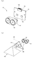
- Fig. 3 shows an exploded perspective view and a perspective view of coupling the body of the lighting apparatus shown in Fig. 2 .
- the body 110 is formed by combining at least two parts.
- the body 110 is formed by combining a first body 110-A with a second body 110-B.
- the light source 120 and the reflector 130 can be easily installed in a receiving recess 115 of the body 110.
- the body 110 includes the receiving recess 115 for receiving the light source 120 and the reflector 130.
- the receiving recess 115 is configured by a side surface 111 and a bottom surface 113.
- the recess of the receiving recess 115 includes a cavity and a groove.
- the side surface 111 of the body 110 is equipped with the light source 120.
- the side surface 111 of the body 110 comes in surface contact with the one side of a substrate 121 of the light source 120. Since the side surface 111 of the body 110 is equipped with the light source 120, the body 110 can easily receive heat from the light source 120.
- the reflector 130 is mounted on the bottom surface 113 of the body 110.
- the side surface 111 of the body 110 may be a predeterminedly curved or may not be curved, for example, a polygonal pillar.
- a portion on which a substrate 121 is placed on the side surface 111 of the body 110 is flat.
- the side surface 111 of the body 110 includes, as shown in Fig. 3 , an mounting recess 117 into which the substrate 121 of the light source 120 is inserted, and the bottom surface of the mounting recess 117 is flat. Since the side surface 111 of the body 110 includes the mounting recess 117, the side surface 111 of the body 110 also comes in surface contact with the lateral surface of the substrate 121 of the light source 120.
- the body 110 can receive more easily the heat from the light source 120. Further, the substrate 121 of the light source 120 can be easily mounted on the inner surface of the body 110.
- the recess of the mounting recess 117 includes a cavity and a groove.
- the body 110 receives the heat from the light source 120 and retains or radiates the heat to the outside. Therefore, it is recommended that the material of the body 110 be a metallic material having thermal conductivity.
- the body 110 may be made of Al or an alloy including A1.
- the body 110 it is desirable for the body 110 to have a cylindrical shape.
- the body can have various shapes without being limited to this.
- the body 110 may have a polygonal box shape.
- the body 110 may have a heat radiating fin (not shown).
- the heat radiating fin (not shown) extends outward from the outer surface of the body 110.
- the body 110 may have a plurality of the heat radiating fins. Otherwise, the heat radiating fin (not shown) may be independent of the body 110 and combined with the body 110.
- the heat radiating fin (not shown) can more improve the heat radiating effect of the body 110 by increasing the surface area of the body 110.
- Fig. 4 is an exploded perspective view of the light source 120 alone of the lighting apparatus shown in Fig. 2 .
- the light source 120 is mounted on the side surface 111 of the body 110.
- the light source 120 includes the substrate 121, a light emitting diode (LED) 123, a lens 125, a lens holder 127 and a connector 129.
- LED light emitting diode
- At least one LED 123, the lens 125, the lens holder 127 and the connector 129 are mounted on one side of the substrate 121.
- the other side of the substrate 121 comes in surface contact with the side surface 111 of the body 110.
- the substrate 121 may include a printed circuit pattern for electrically connecting the LED 123 with the connector 129. Therefore, a printed circuit board (PCB) may be used as the substrate 121.
- PCB printed circuit board
- the substrate 121 When the substrate 121 is flat and the side surface 111 of the body 110 is curved, the substrate 121 is difficult to come in surface contact with the side surface 111 of the body 110. Therefore, though not shown in the drawings, the substrate 121 may be curved in conformity with the curved the side surface 111 of the body 110.
- the LED 123 is a sort of a device emitting light. At least one LED 123 is mounted on the one side of the substrate 121. The LED 123 may have a lateral type or a vertical type. The LED 123 may be at least one of a blue LED, red LED, yellow LED and green LED. Here, the light emitting device is not limited to the LED 123. Any device emitting light like the LED 123 may be used as the light emitting device.
- the LED 123 may further include a fluorescent layer (not shown) having at least one fluorescent material. That is, the fluorescent layer (not shown) surrounding the LED 123 may be further included.
- the fluorescent material included in the fluorescent layer includes at least any one selected from a group consisting of a garnet based material (YAG, TAG), a silicate based material, a nitride based material and an oxynitride based material.
- YAG garnet based material
- TAG silicate based material
- nitride based material a nitride based material
- oxynitride based material an oxynitride based material.
- a green fluorescent material or a red fluorescent material be further included in the fluorescent layer for the purpose of improving a color rendering index and reducing a color temperature.
- the addition ratio of the colors of the fluorescent materials is based on the fact that it is recommended that the green fluorescent material is more used than the red fluorescent material, and the yellow fluorescent material is more used than the green fluorescent material.
- the garnet based material (YAG), the silicate based material and the oxynitride based material are used as the yellow fluorescent material.
- the silicate based material and the oxynitride based material are used as the green fluorescent material.
- the nitride based material is used as the red fluorescent material.
- the fluorescent layer may be mixed with various kinds of the fluorescent materials or may be configured by a layer including the red fluorescent material, a layer including the green fluorescent material and a layer including the yellow fluorescent material, which are formed separately from each other.
- the lens 125 is mounted on one side of the substrate 121 and covers the LED 123.
- the lens 125 decreases the orientation angle of light from the LED 123. That is, the lens 125 collimates the light emitted from the LED 123.
- a general LED emits light having an orientation angle of approximately 120°.
- the lens 125 collimates the light emitted from the LED 123 such that the light has an orientation angle of between about 5° and 15°.
- the lens 125 is relevant to the reflector 130. Specifically, this matter will be described with reference to Fig. 5 .
- Fig. 5 is a perspective view for describing the relation between the reflector 130 and the lens 125 which are shown in Fig. 2 .
- an orthogonal projection 210 of the lens 125 which is formed on the imaginary plane 200, is included in an orthogonal projection 230 of the reflective surface 131, which is formed on the imaginary plane 200.
- the orthogonal projections 210 of the total lenses 125 are also included in the orthogonal projection 230 of the reflective surface 131.
- all of the light emitted from the lens 125 can mostly reach the reflective surface 131 facing the lens 125. Therefore, it is possible to improve the luminous efficiency of the lighting apparatus according to the embodiment of the present disclosure.
- the lens 125 includes the aforementioned fluorescent layer (not shown). Both when the LED 123 includes the fluorescent layer (not shown) and when the LED 123 does not, the lens 125 can include the fluorescent layer (not shown). The detailed description of the fluorescent layer (not shown) will be replaced with that of the aforementioned fluorescent layer (not shown).
- the lens holder 127 is mounted on one side of the substrate 121 and surrounds and fixes the lens 125.
- the lens holder 127 securely fixes the lens 125 to the substrate 121.
- the lens holder 127 surround at least two lenses 125.
- the lens holder 127 integrally surrounds the plurality of the lenses 125, it is possible to reduce the amount of the light lost through the lens 125 and to decrease the intervals among the LEDs 123, thereby reducing the total size of the lighting apparatus.
- the connector 129 is disposed on one lateral side of the substrate 121 and includes a projection 129-1 projecting outward from the substrate 121.
- the projection 129-1 has elasticity acting in an outside direction of the substrate 121. Therefore, when the projection 129-1 is given a predetermined force in an inside direction of the substrate 121, the projection 129-1 is pushed into the inside of the substrate 121.
- a relation between the connector 129 and the connection board 140 will be described with reference to Figs. 2 , 4 and 7 .
- connection board 140 shown in Fig. 2 When the connection board 140 shown in Fig. 2 is mounted on the body 110, the projection 129-1 is pressed by a pad 141 of the connection board 140 shown in Fig. 7 . That is, the connector 129 shown in fig. 4 is compressed to the pad 141 shown in Fig. 7 .
- the connector 129 shown in fig. 4 can be electrically connected to the pad 141 shown in Fig. 7 without a separate wire.
- a separate wire is not used, so that a manual process such as a soldering, etc., is not required.
- the reflector 130 is mounted on the bottom surface 113 of the receiving recess 115 of the body 110, and reflects in a predetermined direction, particularly, in the upper direction of Fig. 2 light from the light source 120 mounted on the side surface 111 of the body 110.
- the reflector 130 may have a poly-pyramid shape. Specifically, a detailed description thereof will be provided with reference to Fig. 6.
- Fig. 6 is a perspective view showing other embodiments of the reflector 130 shown in Fig. 2 .
- the poly-pyramid shape includes not only a geometrically perfect quadrangular shape or a geometrically perfect poly-pyramid shape but also a shape in which the reflective surface 131' of a first reflector 130' shown in the top part of Fig. 6 is curved in the inward direction of the poly-pyramid.
- the poly-pyramid shape includes a shape in which the reflective surface 131" of a second reflector 130" shown in the intermediate part of Fig. 6 is curved in the outward direction of the poly-pyramid.
- the poly-pyramid shape includes a shape in which a predetermined upper portion of a third reflector 130''' shown in the bottom part of Fig. 6 is removed.
- the upper portion of the third reflector 130'' shown in the bottom part of Fig. 6 is the same as a shape formed by removing the upper portion of the reflector 130 shown in Fig. 2 .
- the surface of the upper portion of the reflector 130''' may be, as shown, flat or curved.
- the reflector 130 has the reflective surface 131 and a non-reflective surface.
- the non-reflective surface comes in surface contact with the bottom surface 113 of the body 110.
- the reflective surface 131 reflects the light from the light source 120 in a predetermined direction.
- the reflective surface 131 of the reflector 130 one-to-one corresponds to the light source 120.
- the number of the reflective surfaces 131 is equal to the number of the light source 120, and one reflective surface 131 faces one light source 120.
- the reflector 130 since the number of the light sources 120 is four, the reflector 130 has four reflective surfaces 131 in correspondence with the number of the light sources 120. Therefore, the reflector 130 has a quadrangular pyramid shape. In this case, four triangular facets 131 correspond to the reflective surfaces 131, the bottom triangular facet corresponds to the non-reflective surface. Meanwhile, although Fig. 2 shows that the number of the light sources 120 is four and the reflector 130 has a quadrangular pyramid shape, there is no limit to this. The shape of the reflector 130 is changed according to the number of the light sources 120. For example, if the number of the light sources 120 is three, the reflector 130 has a triangular pyramid shape.
- the reflective surface 131 of the reflector 130 may be a mirror surface in order to increase the reflectance thereof.
- connection board 140 is connected to the body 110. Specifically, the connection board 140 is connected to cover the receiving recess 115 of the body 110. The detailed description thereof will be provided with reference to Fig. 7 .
- Fig. 7 shows the top and bottom perspective views of the connection board 140 shown in Fig. 2 .
- the bottom perspective view is obtained by turning the top perspective view upside down.
- connection board 140 includes an opening 145 through which light reflected from the reflector 130 passes.
- the connection board 140 includes the pad 141 electrically connected to the connector 129 of the light source 120 shown in Fig. 4 , and includes a connector 143 receiving electric power from the outside.
- the pad 141 and the connector 143 are electrically connected with each other through the circuit pattern printed on the connection board 140. That is, the connection board 140 can be a PCB like the substrate 121 of the light source 120. Therefore, the electric power inputted through the connector 143 is transferred to the pad 141, and then the electric power is transferred to the light source 120 because the pad 141 is electrically connected to the connector 129 of the light source 120.
- connection board 140 there is no requirement for a separate wire transferring the electric power to the light source 120. Therefore, this makes it possible to simply assemble the lighting apparatus and to prevent the wire from making the internal configuration of the lighting apparatus complex.
- the area of the opening 145 of the connection board 140 is greater than that of the non-reflective surface of the reflector 130. Because, if not, the light reflected from the reflector 130 is reflected by the connection board 140, so that the luminous efficiency is degraded.
- Fig. 8 is an exploded perspective view for describing another embodiment of the connection board 140 of the lighting apparatus shown in Fig. 2 .
- connection board 140' electrically connects two adjacent substrates 121a and 121b with each other.
- Fig. 8 shows that the connection board 140' electrically connects the two adjacent substrates 121a and 121b with each other, there is no limit to this.
- the connection board 140' can electrically connect two substrates 121a and 121c or 121b and 121d which mutually face each other. Further, the connection board 140' can also electrically connect three or more substrates.
- connection board 140' When the connection board 140' electrically connects the two adjacent substrates 121a and 121b with each other, both ends of the connection board 140' are connected with a connector 129a of a first substrate 121a and a connector 129b of a second substrate 121b, respectively.
- connection board 140' is disposed to contact with the side surface 111 of the body 110.
- the connection board 140' is enclosed with an insulation material so as to insulate the connection board 140' from the body 110. This intends to prevent electrical short-cut between the body 110 and the connection board 140' because the body 110 is usually made of a heat radiating material like A1 that is electrically connected. Meanwhile, when the side surface 111 of the body 110 is coated with an insulation material, the connection board 140' is not necessary to be enclosed with the insulation material.
- connection board 140' can be a flexible board that is easily bent. In a case where the side surface 111 of the body 110 is predeterminedly curved or angular, the flexible connection board 140' can easily come in surface contact with the side surface 111 of the body 110.
- connection board 140' By using the connection board 140', it is possible to simply assemble the lighting apparatus and to remove a soldering process which uses a separate wire. Moreover, the inside of the lighting apparatus can be simply configured for the lighting apparatus to have its smaller size.
- Fig. 9 is a perspective view of the cover 150 alone of the lighting apparatus shown in Fig. 2 .
- the cover 150 includes a support 153 including a coupling recess 153-1 for receiving the lens 125 of the light source 120, surrounding the reflector 130 and being inserted into the receiving recess 115 of the body 110.
- the recess of the coupling recess 153-1 includes a cavity and a groove.
- the cover 150 includes a cover part 151, the support 153, an opening 155 and a fastening hole 157.
- the cover part 151 covers one side of the body 110 including the receiving recess 115.
- the cover part 151 extends from one end of the support 153 in a direction perpendicular to the depth direction of the receiving recess 115 of the body 110. Therefore, the cover part 151 and the body 110 form the appearance of the lighting apparatus according to the embodiment of the present disclosure.
- the support 153 is inserted into the receiving recess 115 of the body 110 and comes in contact with the bottom surface 113 of the body 110, and thus supports the entire cover 150. Accordingly, it is recommended that the length of the support 153 be equivalent to the depth of the receiving recess 115 of the body 110.
- the support 153 surrounds the reflector 130 mounted in the body 110. Therefore, the support 153 is used as a guide path through which the light reflected from the reflector 130 passes outward.
- the support 153 prevents the light reflected from the reflector 130 from being lost within the body 110. Accordingly, the luminous efficiency of the lighting apparatus can be improved.
- an inner surface 153-3 of the support 153 is coated with a reflective material for the purpose of more maximizing the luminous efficiency.
- the support 153 includes the coupling recess 153-1 for receiving the lens 125 of the light source 120 at the time of combining the support 153 with the lens 125 of the light source 120.
- the inner surface 153-3 of the support 153 is placed on the same plane with the light emitting surface (the surface) of the lens 125.
- a path of the light reflected from the reflector 130 is formed by the inner surface 153-3 of the support 153 and the light emitting surface of the lens 125 of the light source 120.
- all of the light reflected from the reflector 130 is reflected by the inner surface 153-3 of the support 153 without being lost within the body 110, so that the light is emitted outward through the opening 155 of the cover 150.
- the fastening hole 157 receives and fixes a fastening portion 173 of the optic plate holder 170.
- the optic plate holder 170 fixes the optic plate 160 to the cover 150 by using the fastening hole 157.
- the optic plate 160 covers the opening 155 of the cover 150 and is disposed on the cover part 151 of the cover 150.
- the optic plate 160 can optically change the light emitted through the opening 155 of the cover 150.
- the optic plate 160 can diffuse the light emitted through the opening 155 of the cover 150.
- the optic plate 160 may include a fluorescent layer (not shown).
- a description of the fluorescent layer can be replaced with the aforementioned description of the fluorescent layer.
- the optic plate 160 can have all of a diffusion function and the fluorescent layer.
- the optic plate holder 170 is fastened to the cover 150 and fixes the optic plate 160.
- the optic plate holder 170 includes a cover part 171, the fastening portion 173 and an opening 175.
- the cover part 171 covers the optic plate 160 and includes the opening 175 through which the light that has passed through the opening 155 of the cover 150 passes.
- the fastening portion 173 extends outward from the cover part 171.
- the fastening portion 173 is inserted and fitted to the fastening hole 157 of the cover 150.
Landscapes
- Engineering & Computer Science (AREA)
- General Engineering & Computer Science (AREA)
- Physics & Mathematics (AREA)
- Microelectronics & Electronic Packaging (AREA)
- Optics & Photonics (AREA)
- Non-Portable Lighting Devices Or Systems Thereof (AREA)
- Fastening Of Light Sources Or Lamp Holders (AREA)
- Arrangement Of Elements, Cooling, Sealing, Or The Like Of Lighting Devices (AREA)
- Led Device Packages (AREA)
Priority Applications (1)
| Application Number | Priority Date | Filing Date | Title |
|---|---|---|---|
| EP14156687.7A EP2738445B1 (fr) | 2010-11-08 | 2011-07-15 | Appareil d'éclairage |
Applications Claiming Priority (5)
| Application Number | Priority Date | Filing Date | Title |
|---|---|---|---|
| KR1020100110561A KR101039653B1 (ko) | 2010-11-08 | 2010-11-08 | 조명 장치 |
| KR1020100110472A KR101171811B1 (ko) | 2010-11-08 | 2010-11-08 | 조명 장치 |
| KR1020100110478A KR101103522B1 (ko) | 2010-11-08 | 2010-11-08 | 조명 장치 |
| KR1020100110562A KR101174260B1 (ko) | 2010-11-08 | 2010-11-08 | 조명 장치 |
| KR1020100110563A KR101174259B1 (ko) | 2010-11-08 | 2010-11-08 | 조명 장치 |
Related Child Applications (2)
| Application Number | Title | Priority Date | Filing Date |
|---|---|---|---|
| EP14156687.7A Division EP2738445B1 (fr) | 2010-11-08 | 2011-07-15 | Appareil d'éclairage |
| EP14156687.7A Division-Into EP2738445B1 (fr) | 2010-11-08 | 2011-07-15 | Appareil d'éclairage |
Publications (2)
| Publication Number | Publication Date |
|---|---|
| EP2450612A1 true EP2450612A1 (fr) | 2012-05-09 |
| EP2450612B1 EP2450612B1 (fr) | 2014-04-30 |
Family
ID=45021986
Family Applications (2)
| Application Number | Title | Priority Date | Filing Date |
|---|---|---|---|
| EP14156687.7A Not-in-force EP2738445B1 (fr) | 2010-11-08 | 2011-07-15 | Appareil d'éclairage |
| EP11174196.3A Active EP2450612B1 (fr) | 2010-11-08 | 2011-07-15 | Appareil d'éclairage |
Family Applications Before (1)
| Application Number | Title | Priority Date | Filing Date |
|---|---|---|---|
| EP14156687.7A Not-in-force EP2738445B1 (fr) | 2010-11-08 | 2011-07-15 | Appareil d'éclairage |
Country Status (4)
| Country | Link |
|---|---|
| US (3) | US8382336B2 (fr) |
| EP (2) | EP2738445B1 (fr) |
| JP (2) | JP5613136B2 (fr) |
| CN (2) | CN104676325B (fr) |
Families Citing this family (12)
| Publication number | Priority date | Publication date | Assignee | Title |
|---|---|---|---|---|
| US7401943B2 (en) * | 2005-06-07 | 2008-07-22 | Fusion Uv Systems, Inc. | Solid-state light sources for curing and surface modification |
| TWI522571B (zh) * | 2012-08-27 | 2016-02-21 | 南臺科技大學 | 照明裝置 |
| DE102012109145A1 (de) * | 2012-09-27 | 2014-03-27 | Osram Opto Semiconductors Gmbh | Ringlichtmodul |
| CN104359044A (zh) * | 2014-10-21 | 2015-02-18 | 泰州市华强照明器材有限公司 | 一种led筒灯 |
| WO2017054233A1 (fr) * | 2015-10-02 | 2017-04-06 | 魏晓敏 | Module de del et disposif d'émission de lumière à del |
| US20170102123A1 (en) * | 2015-10-12 | 2017-04-13 | Randall Dale Raischein | Side-Mounted LED Light Emitting Method and Apparatus |
| US10262466B2 (en) * | 2015-10-14 | 2019-04-16 | Qualcomm Incorporated | Systems and methods for adjusting a combined image visualization based on depth information |
| US11739928B2 (en) * | 2017-08-10 | 2023-08-29 | Archangel Device Llc | Safety light |
| WO2019143903A1 (fr) * | 2018-01-18 | 2019-07-25 | Chia Ming Chen | Mélange de couleurs à partir de différentes sources de lumière |
| US10308468B1 (en) * | 2018-05-30 | 2019-06-04 | The Advance Equipment Manufacturing Company | Drywall banjo tools for applying joint tape |
| CN109185753A (zh) * | 2018-09-29 | 2019-01-11 | 欧普照明股份有限公司 | 线条灯 |
| CN111365693B (zh) * | 2020-03-19 | 2024-02-06 | 福建中科芯源光电科技有限公司 | 一种消除多个cob光源与反光杯配光缺陷的灯具及其方法 |
Citations (4)
| Publication number | Priority date | Publication date | Assignee | Title |
|---|---|---|---|---|
| EP0416253A2 (fr) * | 1989-09-08 | 1991-03-13 | Inotec Gmbh Gesellschaft Für Innovative Technik | Lampe |
| EP1607677A1 (fr) * | 2004-06-17 | 2005-12-21 | Osram Sylvania Inc. | LED lampe avec réflecteur conique |
| EP1826474A1 (fr) * | 2006-02-22 | 2007-08-29 | Optics Lite S.r.L. | Projecteur optique avec source lumineuse à DEL radiale |
| EP1944541A1 (fr) * | 2007-01-15 | 2008-07-16 | Stanley Electric Co., Ltd. | Luminaire |
Family Cites Families (50)
| Publication number | Priority date | Publication date | Assignee | Title |
|---|---|---|---|---|
| IT8214741V0 (it) * | 1982-09-20 | 1982-09-20 | Alberto Carboni | Lampada lanciabile per consentire, da posizioni di sicurezza, una visione immediata dell'ambiente edi chi lo occupa, come preliminare ad operazioni di rischio |
| DE4004821A1 (de) | 1990-02-16 | 1991-08-22 | Bayer Ag | Verfahren zur kernchlorierung von aromatischen kohlenwasserstoffen |
| US5365411A (en) * | 1993-01-06 | 1994-11-15 | Kaufel Group Ltd. | Exit signs with LED illumination |
| JP2000268604A (ja) | 1999-03-19 | 2000-09-29 | Patoraito:Kk | Led表示灯 |
| US6504301B1 (en) * | 1999-09-03 | 2003-01-07 | Lumileds Lighting, U.S., Llc | Non-incandescent lightbulb package using light emitting diodes |
| US6478440B1 (en) * | 2000-03-10 | 2002-11-12 | S.C. Johnson & Son, Inc. | Night light air freshener |
| JP4023079B2 (ja) * | 2000-08-31 | 2007-12-19 | 株式会社日立製作所 | 面状照明装置及びこれを備えた表示装置 |
| TW581850B (en) * | 2001-02-21 | 2004-04-01 | Nippon Sheet Glass Co Ltd | Light-guided plate, planar light source device, and image reading device |
| JP4129570B2 (ja) * | 2001-07-18 | 2008-08-06 | ラボ・スフィア株式会社 | 発光ダイオード照明装置 |
| JP3928384B2 (ja) * | 2001-08-17 | 2007-06-13 | 松下電工株式会社 | Led照明器具 |
| US6663262B2 (en) | 2001-09-10 | 2003-12-16 | 3M Innovative Properties Company | Backlighting transmissive displays |
| AU2002950939A0 (en) * | 2002-08-22 | 2002-09-12 | Ian Thomas Craig | Downlight protector housing |
| KR20070062610A (ko) | 2002-12-26 | 2007-06-15 | 산요덴키가부시키가이샤 | 조명 장치 |
| JP4211029B2 (ja) | 2003-07-17 | 2009-01-21 | 三菱電機株式会社 | 面光源装置 |
| US7101058B2 (en) * | 2003-10-07 | 2006-09-05 | Robert Bosch Gmbh | Light assembly |
| CN1710321A (zh) * | 2004-06-17 | 2005-12-21 | 奥斯兰姆施尔凡尼亚公司 | 带有锥形聚焦的光导装置的发光二极管灯 |
| JP4746301B2 (ja) | 2004-10-01 | 2011-08-10 | ライツ・アドバンスト・テクノロジー株式会社 | バックライトユニット |
| JP2006310549A (ja) * | 2005-04-28 | 2006-11-09 | Yoshikawa Kasei Kk | 照明装置および撮像装置 |
| JP4548219B2 (ja) * | 2005-05-25 | 2010-09-22 | パナソニック電工株式会社 | 電子部品用ソケット |
| TWI262276B (en) * | 2005-11-24 | 2006-09-21 | Ind Tech Res Inst | Illumination module |
| CN1978979B (zh) * | 2005-12-05 | 2010-05-05 | 财团法人工业技术研究院 | 照明模块的结构 |
| TW200728851A (en) * | 2006-01-20 | 2007-08-01 | Hon Hai Prec Ind Co Ltd | Backlight module |
| TW200817777A (en) | 2006-08-03 | 2008-04-16 | Harison Toshiba Lighting Corp | Hollow type flat lighting system |
| KR100844757B1 (ko) * | 2006-08-24 | 2008-07-07 | 엘지이노텍 주식회사 | 광원 장치 및 이를 이용한 디스플레이 장치 |
| CN100549499C (zh) * | 2006-10-11 | 2009-10-14 | 深圳市邦贝尔电子有限公司 | Led路灯光源 |
| EP2573812B1 (fr) * | 2006-10-12 | 2017-08-16 | Panasonic Intellectual Property Management Co., Ltd. | Appareil Luminescent |
| CN101589267A (zh) * | 2007-01-22 | 2009-11-25 | 夏普株式会社 | 背光装置以及使用背光装置的平面显示装置 |
| US20080175003A1 (en) * | 2007-01-22 | 2008-07-24 | Cheng Home Electronics Co., Ltd. | Led sunken lamp |
| KR100860401B1 (ko) | 2007-02-06 | 2008-09-26 | 주식회사 이상테크 | 발광다이오드를 이용한 자동차용 후미등 |
| US20080217643A1 (en) * | 2007-03-07 | 2008-09-11 | Chung Yiu Lin | Light-emitting diode and heat radiating unit therefor |
| KR20080086245A (ko) * | 2007-03-22 | 2008-09-25 | 삼성전자주식회사 | 백라이트 어셈블리 및 그를 포함하는 액정 표시 장치 |
| KR20080098762A (ko) | 2007-05-07 | 2008-11-12 | 한학수 | 엘이디 램프를 이용한 조명장치 |
| US8029164B2 (en) * | 2007-05-21 | 2011-10-04 | Goldeneye, Inc. | LED light recycling cavity with integrated optics |
| CN201062730Y (zh) * | 2007-06-12 | 2008-05-21 | 宁翔科技股份有限公司 | Led光棒串接结构 |
| CN201083924Y (zh) * | 2007-06-22 | 2008-07-09 | 群康科技(深圳)有限公司 | 背光模组和液晶显示装置 |
| JP4124479B1 (ja) | 2007-10-16 | 2008-07-23 | 株式会社モモ・アライアンス | 照明装置 |
| JP5280106B2 (ja) * | 2007-12-07 | 2013-09-04 | デクセリアルズ株式会社 | 光源装置および表示装置 |
| ITRA20080008A1 (it) * | 2008-02-07 | 2009-08-08 | Celestino Costa | Scatole "universali" per faretti d'illuminazione per controsoffiti di ogni tipo. |
| CN201237173Y (zh) * | 2008-06-17 | 2009-05-13 | 俊光科技有限公司 | 一种发光二极管灯具 |
| CN102057209A (zh) * | 2008-07-10 | 2011-05-11 | 夏普株式会社 | 背光源装置和使用该背光源装置的平面显示装置 |
| KR101016496B1 (ko) * | 2008-11-10 | 2011-02-24 | 이정규 | 발광다이오드 조명장치 |
| TW201020451A (en) * | 2008-11-28 | 2010-06-01 | bao-xiu Liu | Improved light-convergence apparatus of LED lamp |
| CN102265086A (zh) * | 2008-12-25 | 2011-11-30 | 夏普株式会社 | 框架、光源装置、显示装置和电视接收机 |
| US8366290B2 (en) * | 2009-01-14 | 2013-02-05 | Mag Instrument, Inc. | Portable lighting device |
| JP2010164810A (ja) * | 2009-01-16 | 2010-07-29 | Ae Tekku Kk | 照明装置 |
| JP4365884B1 (ja) * | 2009-02-09 | 2009-11-18 | 株式会社ケノス | Led基板の取付装置 |
| KR101132217B1 (ko) | 2009-02-13 | 2012-04-02 | 주식회사 태평양기술 | 비대칭 반사 led 조명기구 |
| JP2010225791A (ja) * | 2009-03-23 | 2010-10-07 | Stanley Electric Co Ltd | 半導体発光装置 |
| KR101058899B1 (ko) | 2009-04-24 | 2011-08-23 | 김해룡 | 자동차 램프용 회로기판 구조체 |
| US8419238B2 (en) * | 2010-03-16 | 2013-04-16 | A.L.P. Lighting & Ceiling Products, Inc. | Lighting fixtures having enhanced heat sink performance |
-
2011
- 2011-07-15 EP EP14156687.7A patent/EP2738445B1/fr not_active Not-in-force
- 2011-07-15 EP EP11174196.3A patent/EP2450612B1/fr active Active
- 2011-08-09 US US13/206,224 patent/US8382336B2/en active Active
- 2011-09-08 CN CN201510070599.0A patent/CN104676325B/zh active Active
- 2011-09-08 CN CN201110276041.XA patent/CN102466159B/zh active Active
- 2011-11-02 JP JP2011240787A patent/JP5613136B2/ja active Active
-
2012
- 2012-09-11 US US13/610,481 patent/US9383066B2/en active Active
-
2014
- 2014-09-05 JP JP2014181242A patent/JP5806771B2/ja active Active
-
2016
- 2016-06-01 US US15/170,598 patent/US10234103B2/en active Active
Patent Citations (4)
| Publication number | Priority date | Publication date | Assignee | Title |
|---|---|---|---|---|
| EP0416253A2 (fr) * | 1989-09-08 | 1991-03-13 | Inotec Gmbh Gesellschaft Für Innovative Technik | Lampe |
| EP1607677A1 (fr) * | 2004-06-17 | 2005-12-21 | Osram Sylvania Inc. | LED lampe avec réflecteur conique |
| EP1826474A1 (fr) * | 2006-02-22 | 2007-08-29 | Optics Lite S.r.L. | Projecteur optique avec source lumineuse à DEL radiale |
| EP1944541A1 (fr) * | 2007-01-15 | 2008-07-16 | Stanley Electric Co., Ltd. | Luminaire |
Also Published As
| Publication number | Publication date |
|---|---|
| EP2738445B1 (fr) | 2018-01-10 |
| EP2450612B1 (fr) | 2014-04-30 |
| JP2012104479A (ja) | 2012-05-31 |
| US8382336B2 (en) | 2013-02-26 |
| US20160290596A1 (en) | 2016-10-06 |
| JP2014222680A (ja) | 2014-11-27 |
| CN102466159A (zh) | 2012-05-23 |
| CN104676325B (zh) | 2019-04-09 |
| US10234103B2 (en) | 2019-03-19 |
| CN104676325A (zh) | 2015-06-03 |
| US9383066B2 (en) | 2016-07-05 |
| US20110292638A1 (en) | 2011-12-01 |
| CN102466159B (zh) | 2015-03-25 |
| US20130003349A1 (en) | 2013-01-03 |
| EP2738445A1 (fr) | 2014-06-04 |
| JP5806771B2 (ja) | 2015-11-10 |
| JP5613136B2 (ja) | 2014-10-22 |
Similar Documents
| Publication | Publication Date | Title |
|---|---|---|
| US10234103B2 (en) | Lighting apparatus | |
| KR101293163B1 (ko) | 광학 소자 조립용 맞춤핀 및 led를 포함하는 광 방출모듈 | |
| JP6285102B2 (ja) | 照明装置 | |
| EP2551584A2 (fr) | Lampe à DEL de type ampoule | |
| US9829181B2 (en) | Lighting device | |
| US20170067618A1 (en) | Lighting apparatus | |
| WO2013128732A1 (fr) | Dispositif électroluminescent et appareil d'éclairage utilisant celui-ci | |
| EP2753873B1 (fr) | Dispositif d'éclairage | |
| JP4905630B2 (ja) | 照明装置 | |
| JP2007027325A5 (fr) | ||
| CN203848204U (zh) | 照明用光源 | |
| JP2013084535A (ja) | Ledユニット | |
| JP2016058223A (ja) | 光源ユニット、照明ランプ及び照明装置 | |
| KR101174259B1 (ko) | 조명 장치 | |
| JP5877366B2 (ja) | Ledユニット | |
| KR101103522B1 (ko) | 조명 장치 | |
| KR101171811B1 (ko) | 조명 장치 | |
| JP2012059370A (ja) | 電球型ledランプ | |
| KR101039653B1 (ko) | 조명 장치 | |
| KR101174260B1 (ko) | 조명 장치 | |
| JP6291146B1 (ja) | レトロフィット電球 | |
| KR102014174B1 (ko) | 조명 장치 | |
| KR20150111219A (ko) | 조명기기 | |
| KR20150031699A (ko) | 조명 장치 |
Legal Events
| Date | Code | Title | Description |
|---|---|---|---|
| PUAI | Public reference made under article 153(3) epc to a published international application that has entered the european phase |
Free format text: ORIGINAL CODE: 0009012 |
|
| 17P | Request for examination filed |
Effective date: 20110808 |
|
| AK | Designated contracting states |
Kind code of ref document: A1 Designated state(s): AL AT BE BG CH CY CZ DE DK EE ES FI FR GB GR HR HU IE IS IT LI LT LU LV MC MK MT NL NO PL PT RO RS SE SI SK SM TR |
|
| AX | Request for extension of the european patent |
Extension state: BA ME |
|
| RIC1 | Information provided on ipc code assigned before grant |
Ipc: F21K 99/00 20100101AFI20131118BHEP |
|
| GRAP | Despatch of communication of intention to grant a patent |
Free format text: ORIGINAL CODE: EPIDOSNIGR1 |
|
| INTG | Intention to grant announced |
Effective date: 20140114 |
|
| GRAS | Grant fee paid |
Free format text: ORIGINAL CODE: EPIDOSNIGR3 |
|
| GRAA | (expected) grant |
Free format text: ORIGINAL CODE: 0009210 |
|
| AK | Designated contracting states |
Kind code of ref document: B1 Designated state(s): AL AT BE BG CH CY CZ DE DK EE ES FI FR GB GR HR HU IE IS IT LI LT LU LV MC MK MT NL NO PL PT RO RS SE SI SK SM TR |
|
| REG | Reference to a national code |
Ref country code: GB Ref legal event code: FG4D Ref country code: CH Ref legal event code: EP |
|
| REG | Reference to a national code |
Ref country code: AT Ref legal event code: REF Ref document number: 665389 Country of ref document: AT Kind code of ref document: T Effective date: 20140515 |
|
| REG | Reference to a national code |
Ref country code: IE Ref legal event code: FG4D |
|
| REG | Reference to a national code |
Ref country code: DE Ref legal event code: R096 Ref document number: 602011006487 Country of ref document: DE Effective date: 20140612 |
|
| REG | Reference to a national code |
Ref country code: NL Ref legal event code: T3 |
|
| REG | Reference to a national code |
Ref country code: AT Ref legal event code: MK05 Ref document number: 665389 Country of ref document: AT Kind code of ref document: T Effective date: 20140430 |
|
| REG | Reference to a national code |
Ref country code: LT Ref legal event code: MG4D |
|
| PG25 | Lapsed in a contracting state [announced via postgrant information from national office to epo] |
Ref country code: GR Free format text: LAPSE BECAUSE OF FAILURE TO SUBMIT A TRANSLATION OF THE DESCRIPTION OR TO PAY THE FEE WITHIN THE PRESCRIBED TIME-LIMIT Effective date: 20140731 Ref country code: CY Free format text: LAPSE BECAUSE OF FAILURE TO SUBMIT A TRANSLATION OF THE DESCRIPTION OR TO PAY THE FEE WITHIN THE PRESCRIBED TIME-LIMIT Effective date: 20140430 Ref country code: LT Free format text: LAPSE BECAUSE OF FAILURE TO SUBMIT A TRANSLATION OF THE DESCRIPTION OR TO PAY THE FEE WITHIN THE PRESCRIBED TIME-LIMIT Effective date: 20140430 Ref country code: BG Free format text: LAPSE BECAUSE OF FAILURE TO SUBMIT A TRANSLATION OF THE DESCRIPTION OR TO PAY THE FEE WITHIN THE PRESCRIBED TIME-LIMIT Effective date: 20140730 Ref country code: NO Free format text: LAPSE BECAUSE OF FAILURE TO SUBMIT A TRANSLATION OF THE DESCRIPTION OR TO PAY THE FEE WITHIN THE PRESCRIBED TIME-LIMIT Effective date: 20140730 Ref country code: IS Free format text: LAPSE BECAUSE OF FAILURE TO SUBMIT A TRANSLATION OF THE DESCRIPTION OR TO PAY THE FEE WITHIN THE PRESCRIBED TIME-LIMIT Effective date: 20140830 Ref country code: FI Free format text: LAPSE BECAUSE OF FAILURE TO SUBMIT A TRANSLATION OF THE DESCRIPTION OR TO PAY THE FEE WITHIN THE PRESCRIBED TIME-LIMIT Effective date: 20140430 |
|
| PG25 | Lapsed in a contracting state [announced via postgrant information from national office to epo] |
Ref country code: SE Free format text: LAPSE BECAUSE OF FAILURE TO SUBMIT A TRANSLATION OF THE DESCRIPTION OR TO PAY THE FEE WITHIN THE PRESCRIBED TIME-LIMIT Effective date: 20140430 Ref country code: ES Free format text: LAPSE BECAUSE OF FAILURE TO SUBMIT A TRANSLATION OF THE DESCRIPTION OR TO PAY THE FEE WITHIN THE PRESCRIBED TIME-LIMIT Effective date: 20140430 Ref country code: HR Free format text: LAPSE BECAUSE OF FAILURE TO SUBMIT A TRANSLATION OF THE DESCRIPTION OR TO PAY THE FEE WITHIN THE PRESCRIBED TIME-LIMIT Effective date: 20140430 Ref country code: RS Free format text: LAPSE BECAUSE OF FAILURE TO SUBMIT A TRANSLATION OF THE DESCRIPTION OR TO PAY THE FEE WITHIN THE PRESCRIBED TIME-LIMIT Effective date: 20140430 Ref country code: AT Free format text: LAPSE BECAUSE OF FAILURE TO SUBMIT A TRANSLATION OF THE DESCRIPTION OR TO PAY THE FEE WITHIN THE PRESCRIBED TIME-LIMIT Effective date: 20140430 Ref country code: PL Free format text: LAPSE BECAUSE OF FAILURE TO SUBMIT A TRANSLATION OF THE DESCRIPTION OR TO PAY THE FEE WITHIN THE PRESCRIBED TIME-LIMIT Effective date: 20140430 Ref country code: LV Free format text: LAPSE BECAUSE OF FAILURE TO SUBMIT A TRANSLATION OF THE DESCRIPTION OR TO PAY THE FEE WITHIN THE PRESCRIBED TIME-LIMIT Effective date: 20140430 |
|
| PG25 | Lapsed in a contracting state [announced via postgrant information from national office to epo] |
Ref country code: PT Free format text: LAPSE BECAUSE OF FAILURE TO SUBMIT A TRANSLATION OF THE DESCRIPTION OR TO PAY THE FEE WITHIN THE PRESCRIBED TIME-LIMIT Effective date: 20140901 |
|
| PG25 | Lapsed in a contracting state [announced via postgrant information from national office to epo] |
Ref country code: EE Free format text: LAPSE BECAUSE OF FAILURE TO SUBMIT A TRANSLATION OF THE DESCRIPTION OR TO PAY THE FEE WITHIN THE PRESCRIBED TIME-LIMIT Effective date: 20140430 Ref country code: SK Free format text: LAPSE BECAUSE OF FAILURE TO SUBMIT A TRANSLATION OF THE DESCRIPTION OR TO PAY THE FEE WITHIN THE PRESCRIBED TIME-LIMIT Effective date: 20140430 Ref country code: BE Free format text: LAPSE BECAUSE OF FAILURE TO SUBMIT A TRANSLATION OF THE DESCRIPTION OR TO PAY THE FEE WITHIN THE PRESCRIBED TIME-LIMIT Effective date: 20140430 Ref country code: RO Free format text: LAPSE BECAUSE OF FAILURE TO SUBMIT A TRANSLATION OF THE DESCRIPTION OR TO PAY THE FEE WITHIN THE PRESCRIBED TIME-LIMIT Effective date: 20140430 Ref country code: DK Free format text: LAPSE BECAUSE OF FAILURE TO SUBMIT A TRANSLATION OF THE DESCRIPTION OR TO PAY THE FEE WITHIN THE PRESCRIBED TIME-LIMIT Effective date: 20140430 Ref country code: CZ Free format text: LAPSE BECAUSE OF FAILURE TO SUBMIT A TRANSLATION OF THE DESCRIPTION OR TO PAY THE FEE WITHIN THE PRESCRIBED TIME-LIMIT Effective date: 20140430 |
|
| REG | Reference to a national code |
Ref country code: DE Ref legal event code: R097 Ref document number: 602011006487 Country of ref document: DE |
|
| PG25 | Lapsed in a contracting state [announced via postgrant information from national office to epo] |
Ref country code: LU Free format text: LAPSE BECAUSE OF FAILURE TO SUBMIT A TRANSLATION OF THE DESCRIPTION OR TO PAY THE FEE WITHIN THE PRESCRIBED TIME-LIMIT Effective date: 20140715 |
|
| REG | Reference to a national code |
Ref country code: CH Ref legal event code: PL |
|
| PLBE | No opposition filed within time limit |
Free format text: ORIGINAL CODE: 0009261 |
|
| STAA | Information on the status of an ep patent application or granted ep patent |
Free format text: STATUS: NO OPPOSITION FILED WITHIN TIME LIMIT |
|
| PG25 | Lapsed in a contracting state [announced via postgrant information from national office to epo] |
Ref country code: IT Free format text: LAPSE BECAUSE OF FAILURE TO SUBMIT A TRANSLATION OF THE DESCRIPTION OR TO PAY THE FEE WITHIN THE PRESCRIBED TIME-LIMIT Effective date: 20140430 |
|
| 26N | No opposition filed |
Effective date: 20150202 |
|
| REG | Reference to a national code |
Ref country code: IE Ref legal event code: MM4A |
|
| PG25 | Lapsed in a contracting state [announced via postgrant information from national office to epo] |
Ref country code: CH Free format text: LAPSE BECAUSE OF NON-PAYMENT OF DUE FEES Effective date: 20140731 Ref country code: LI Free format text: LAPSE BECAUSE OF NON-PAYMENT OF DUE FEES Effective date: 20140731 |
|
| REG | Reference to a national code |
Ref country code: DE Ref legal event code: R097 Ref document number: 602011006487 Country of ref document: DE Effective date: 20150202 |
|
| PG25 | Lapsed in a contracting state [announced via postgrant information from national office to epo] |
Ref country code: SI Free format text: LAPSE BECAUSE OF FAILURE TO SUBMIT A TRANSLATION OF THE DESCRIPTION OR TO PAY THE FEE WITHIN THE PRESCRIBED TIME-LIMIT Effective date: 20140430 |
|
| PG25 | Lapsed in a contracting state [announced via postgrant information from national office to epo] |
Ref country code: IE Free format text: LAPSE BECAUSE OF NON-PAYMENT OF DUE FEES Effective date: 20140715 |
|
| PG25 | Lapsed in a contracting state [announced via postgrant information from national office to epo] |
Ref country code: SM Free format text: LAPSE BECAUSE OF FAILURE TO SUBMIT A TRANSLATION OF THE DESCRIPTION OR TO PAY THE FEE WITHIN THE PRESCRIBED TIME-LIMIT Effective date: 20140430 Ref country code: MC Free format text: LAPSE BECAUSE OF FAILURE TO SUBMIT A TRANSLATION OF THE DESCRIPTION OR TO PAY THE FEE WITHIN THE PRESCRIBED TIME-LIMIT Effective date: 20140430 |
|
| REG | Reference to a national code |
Ref country code: FR Ref legal event code: PLFP Year of fee payment: 6 |
|
| PG25 | Lapsed in a contracting state [announced via postgrant information from national office to epo] |
Ref country code: MT Free format text: LAPSE BECAUSE OF FAILURE TO SUBMIT A TRANSLATION OF THE DESCRIPTION OR TO PAY THE FEE WITHIN THE PRESCRIBED TIME-LIMIT Effective date: 20140430 |
|
| PG25 | Lapsed in a contracting state [announced via postgrant information from national office to epo] |
Ref country code: HU Free format text: LAPSE BECAUSE OF FAILURE TO SUBMIT A TRANSLATION OF THE DESCRIPTION OR TO PAY THE FEE WITHIN THE PRESCRIBED TIME-LIMIT; INVALID AB INITIO Effective date: 20110715 Ref country code: TR Free format text: LAPSE BECAUSE OF FAILURE TO SUBMIT A TRANSLATION OF THE DESCRIPTION OR TO PAY THE FEE WITHIN THE PRESCRIBED TIME-LIMIT Effective date: 20140430 |
|
| REG | Reference to a national code |
Ref country code: FR Ref legal event code: PLFP Year of fee payment: 7 |
|
| REG | Reference to a national code |
Ref country code: FR Ref legal event code: PLFP Year of fee payment: 8 |
|
| PG25 | Lapsed in a contracting state [announced via postgrant information from national office to epo] |
Ref country code: MK Free format text: LAPSE BECAUSE OF FAILURE TO SUBMIT A TRANSLATION OF THE DESCRIPTION OR TO PAY THE FEE WITHIN THE PRESCRIBED TIME-LIMIT Effective date: 20140430 |
|
| PG25 | Lapsed in a contracting state [announced via postgrant information from national office to epo] |
Ref country code: AL Free format text: LAPSE BECAUSE OF FAILURE TO SUBMIT A TRANSLATION OF THE DESCRIPTION OR TO PAY THE FEE WITHIN THE PRESCRIBED TIME-LIMIT Effective date: 20140430 |
|
| REG | Reference to a national code |
Ref country code: GB Ref legal event code: 732E Free format text: REGISTERED BETWEEN 20210722 AND 20210728 Ref country code: NL Ref legal event code: PD Owner name: SUZHOU LEKIN SEMICONDUCTOR CO., LTD.; CN Free format text: DETAILS ASSIGNMENT: CHANGE OF OWNER(S), ASSIGNMENT; FORMER OWNER NAME: LG INNOTEK CO., LTD. Effective date: 20210719 |
|
| REG | Reference to a national code |
Ref country code: DE Ref legal event code: R081 Ref document number: 602011006487 Country of ref document: DE Owner name: SUZHOU LEKIN SEMICONDUCTOR CO. LTD., TAICANG, CN Free format text: FORMER OWNER: LG INNOTEK CO., LTD., SEOUL, KR |
|
| PGFP | Annual fee paid to national office [announced via postgrant information from national office to epo] |
Ref country code: NL Payment date: 20220615 Year of fee payment: 12 Ref country code: GB Payment date: 20220606 Year of fee payment: 12 |
|
| PGFP | Annual fee paid to national office [announced via postgrant information from national office to epo] |
Ref country code: FR Payment date: 20220609 Year of fee payment: 12 |
|
| PGFP | Annual fee paid to national office [announced via postgrant information from national office to epo] |
Ref country code: DE Payment date: 20220608 Year of fee payment: 12 |
|
| REG | Reference to a national code |
Ref country code: DE Ref legal event code: R119 Ref document number: 602011006487 Country of ref document: DE |
|
| REG | Reference to a national code |
Ref country code: NL Ref legal event code: MM Effective date: 20230801 |
|
| GBPC | Gb: european patent ceased through non-payment of renewal fee |
Effective date: 20230715 |
|
| PG25 | Lapsed in a contracting state [announced via postgrant information from national office to epo] |
Ref country code: NL Free format text: LAPSE BECAUSE OF NON-PAYMENT OF DUE FEES Effective date: 20230801 |
|
| PG25 | Lapsed in a contracting state [announced via postgrant information from national office to epo] |
Ref country code: NL Free format text: LAPSE BECAUSE OF NON-PAYMENT OF DUE FEES Effective date: 20230801 Ref country code: DE Free format text: LAPSE BECAUSE OF NON-PAYMENT OF DUE FEES Effective date: 20240201 Ref country code: GB Free format text: LAPSE BECAUSE OF NON-PAYMENT OF DUE FEES Effective date: 20230715 |