EP2450209A2 - Sonnenschutzvorrichtung für Fahrzeuge - Google Patents
Sonnenschutzvorrichtung für Fahrzeuge Download PDFInfo
- Publication number
- EP2450209A2 EP2450209A2 EP11187512A EP11187512A EP2450209A2 EP 2450209 A2 EP2450209 A2 EP 2450209A2 EP 11187512 A EP11187512 A EP 11187512A EP 11187512 A EP11187512 A EP 11187512A EP 2450209 A2 EP2450209 A2 EP 2450209A2
- Authority
- EP
- European Patent Office
- Prior art keywords
- shading sheet
- directions
- vehicle
- winding
- wire
- Prior art date
- Legal status (The legal status is an assumption and is not a legal conclusion. Google has not performed a legal analysis and makes no representation as to the accuracy of the status listed.)
- Granted
Links
- 238000004804 winding Methods 0.000 claims abstract description 70
- 230000000717 retained effect Effects 0.000 claims abstract description 27
- 235000021189 garnishes Nutrition 0.000 description 27
- 230000002829 reductive effect Effects 0.000 description 11
- 239000000463 material Substances 0.000 description 8
- 238000000034 method Methods 0.000 description 7
- 230000036961 partial effect Effects 0.000 description 6
- 230000003247 decreasing effect Effects 0.000 description 5
- 230000007423 decrease Effects 0.000 description 3
- 239000011347 resin Substances 0.000 description 3
- 229920005989 resin Polymers 0.000 description 3
- 238000003825 pressing Methods 0.000 description 2
- 230000002441 reversible effect Effects 0.000 description 2
- 229910000831 Steel Inorganic materials 0.000 description 1
- XAGFODPZIPBFFR-UHFFFAOYSA-N aluminium Chemical compound [Al] XAGFODPZIPBFFR-UHFFFAOYSA-N 0.000 description 1
- 229910052782 aluminium Inorganic materials 0.000 description 1
- 229920003235 aromatic polyamide Polymers 0.000 description 1
- 230000005540 biological transmission Effects 0.000 description 1
- 239000011248 coating agent Substances 0.000 description 1
- 238000000576 coating method Methods 0.000 description 1
- 230000001143 conditioned effect Effects 0.000 description 1
- 239000013013 elastic material Substances 0.000 description 1
- 238000001125 extrusion Methods 0.000 description 1
- 239000011521 glass Substances 0.000 description 1
- 229920001778 nylon Polymers 0.000 description 1
- 238000007789 sealing Methods 0.000 description 1
- 239000010959 steel Substances 0.000 description 1
- 238000003466 welding Methods 0.000 description 1
Images




Classifications
-
- B—PERFORMING OPERATIONS; TRANSPORTING
- B60—VEHICLES IN GENERAL
- B60J—WINDOWS, WINDSCREENS, NON-FIXED ROOFS, DOORS, OR SIMILAR DEVICES FOR VEHICLES; REMOVABLE EXTERNAL PROTECTIVE COVERINGS SPECIALLY ADAPTED FOR VEHICLES
- B60J7/00—Non-fixed roofs; Roofs with movable panels, e.g. rotary sunroofs
- B60J7/0007—Non-fixed roofs; Roofs with movable panels, e.g. rotary sunroofs moveable head-liners, screens, curtains or blinds for ceilings
- B60J7/0015—Non-fixed roofs; Roofs with movable panels, e.g. rotary sunroofs moveable head-liners, screens, curtains or blinds for ceilings roller blind
-
- B—PERFORMING OPERATIONS; TRANSPORTING
- B60—VEHICLES IN GENERAL
- B60J—WINDOWS, WINDSCREENS, NON-FIXED ROOFS, DOORS, OR SIMILAR DEVICES FOR VEHICLES; REMOVABLE EXTERNAL PROTECTIVE COVERINGS SPECIALLY ADAPTED FOR VEHICLES
- B60J1/00—Windows; Windscreens; Accessories therefor
- B60J1/20—Accessories, e.g. wind deflectors, blinds
- B60J1/2011—Blinds; curtains or screens reducing heat or light intensity
- B60J1/2013—Roller blinds
- B60J1/2019—Roller blinds powered, e.g. by electric, hydraulic or pneumatic actuators
- B60J1/2025—Roller blinds powered, e.g. by electric, hydraulic or pneumatic actuators with flexible actuating elements connected to the draw bar for pulling only, e.g. cords, wires or cables
-
- B—PERFORMING OPERATIONS; TRANSPORTING
- B60—VEHICLES IN GENERAL
- B60J—WINDOWS, WINDSCREENS, NON-FIXED ROOFS, DOORS, OR SIMILAR DEVICES FOR VEHICLES; REMOVABLE EXTERNAL PROTECTIVE COVERINGS SPECIALLY ADAPTED FOR VEHICLES
- B60J1/00—Windows; Windscreens; Accessories therefor
- B60J1/20—Accessories, e.g. wind deflectors, blinds
- B60J1/2011—Blinds; curtains or screens reducing heat or light intensity
- B60J1/2013—Roller blinds
- B60J1/2036—Roller blinds characterised by structural elements
- B60J1/2058—Springs for compensating the number of windings of the blind on the tube in case winding tube and draw bar are driven together
Definitions
- This disclosure generally relates to a sunshade apparatus for a vehicle.
- a garnish attached to an end of the shading sheet is equipped with a leaf spring at both ends of the garnish for the purpose of adjusting a shading sheet to stay open at a desired position against the winding force of a retracting unit.
- a frictional force is produced by each leaf spring pressing against a corresponding guide rail and works against a biasing force in a retraction direction to maintain the opening state of the sunshade apparatus.
- a garnish and a retracting unit for winding a shading sheet are connected by wires for a purpose of reducing operational force. Winding directions of the wires and the shading sheet are opposite to each other in a manner so that when the shading sheet is wound off, a retracting unit winds in the wires in turn.
- Spring biased guide rollers provide tensional forces to the wires and the shading sheet to balance the tensional force on the wire and the tensional force on the shading sheet.
- the shading sheet includes the garnish at the front end, and the garnish is supported in a manner to slide freely along guide rails intermediated by shoes.
- a sunshade apparatus for a vehicle includes a shading sheet, which opens and closes a light transmitting portion of a vehicle roof, a pair of holding members, which retains the shading sheet, a winding member, which winds the shading sheet and the holding members.
- the shading sheet is retained at a pair of edge portions of the shading sheet, which is opposing each other and extending in shading sheet opening-closing directions by the holding members.
- the holding members are retained to the winding member in a manner so that winding in at one end in turn winds off the other end and a direction of movement thereof is reversed at a direction change member positioned at a distance from the winding member in the shading sheet opening-closing directions, and the winding member includes a biasing member balancing tensional forces acting in the shading sheet opening-closing directions at one end and the other end of each of the holding members.
- the shading sheet By a tensional force balanced in the shading sheet opening-closing directions being applied to the shading sheet via the holding members, the shading sheet is retained at a desired position and an operational force for opening or closing the shading sheet is decreased compared to when a position of the desired position of the shading sheet is retained by a frictional force. Also, the shading sheet is retained at both edge portions by the holding members with the tensional force acting in a vehicle upward-downward directions, therefore the slacking that may occur at a middle portion of the shading sheet is decreased.
- each holding member is a wire and the shading sheet is engaged to each wire by enfolding the wire by the corresponding edge portion of the shading sheet.
- each holding member By forming the holding members with wires, a thickness of each holding member is reduced.
- the shading sheet is engaged to each of the holding members by enfolding the corresponding edge portion around the holding member, so that each of the holding members is free from the restriction of the shading sheet to maintain the tensional force with less effort.
- each wire is arranged side by side in opposing directions of the edge portions of the shading sheet to form an inner portion and an outer portion by being folded back at the direction change member.
- the inner portion includes a holding portion, which engages to the shading sheet.
- the shading sheet includes a moving member at an end in the shading sheet opening-closing directions, and the moving member is engaged at both ends of the moving member in the opposing directions of the edge portions of the shading sheet to the wires to be biased by wires toward the opposing directions.
- the moving member is centered by being biased by the holding members in both the shading sheet opening-closing directions and the opposing directions. Therefore, the members for the centering are made unnecessary and the total number of necessary parts is reduced. At the same time, frictional forces available when sliding such members are suppressed and the operational force is reduced.
- the sunshade apparatus for the vehicle further includes a guiding member, which guides each of the wires toward a corresponding winding member portion.
- the guiding member biases the wire toward the opposing directions of the edge portions of the shading sheet for winding each wire in a line to the corresponding winding member portion.
- An end position of each of the wires at a corresponding winding member portion shifts in the opposing directions so that the diameter at one end where the wires are being wound off at one end is kept equal with the diameter at the other end where the wires are being wound in.
- the diameter at the winding member portion is changed according to the length of the wound wires 21 to equal with the diameter at the retracted portion of the shading sheet, so that a torque exerted on the winding member is equilibrated, thus operational force of the sunshade apparatus for the vehicle is reduced.
- the wires are guided to the winding member portion with a biasing force inwardly in the opposing direction, in order to avoid the wires becoming loose.
- an embodiment of the sunshade apparatus for the vehicle includes guide rails for guiding the moving member in the shading sheet opening-closing direction.
- Each of the guide rails includes a contact portion that contacts the corresponding edge portion at the opposing ends of the shading sheet for tensioning the wires and the shading sheet toward the opposing directions.
- the holding members as holding members makes the shading sheet vulnerable to slacking inwardly in the opposing directions, however, the contact portions generate tensional forces that bias the wires and the shading sheet outwardly in the opposing directions, thus, while reducing the thickness the holding members, slacking of the shading sheet is controlled favorably.
- each of the guide rails is curved in a manner that a middle portion in the shading sheet opening and closing direction is projected in the vehicle upward direction.
- Each of the contact portions is a slanted portion being bent from an inner edge in the opposing directions of the corresponding guide rail toward a different direction from the opposing directions.
- An overlap of the edge portion at opposing ends of the shading sheet over the slanted portion of the corresponding guide rail is defined to be larger at the middle portion in the shading sheet opening-closing directions of the guide rail compared to the overlap defined at the both end portions in the shading sheet opening-closing directions of the guide rail.
- More slacking of the shading sheet may occur at the middle portion in the shading sheet opening-closing directions, however, curving the guide rails to project in the vehicle upward direction provides a larger area of the edge portion of the shading sheet that interacts with the corresponding contact portions relative to the area at both end portions.
- a larger tensional force is generated at the middle portion of the shading sheet, so that the slacking of the shading sheet is controlled favorably at where more slacking may occur compared to at the both end portions in the shading sheet opening-closing directions of the shading sheet where slacking is less.
- the biasing member is contained within the winding member.
- each biasing member is a torsion spring.
- the biasing members may be contained within the winding member so that the thickness of the winding member is reduced.
- Fig. 1 is a perspective view of a vehicle roof in which a sunshade apparatus according to a first embodiment is installed;
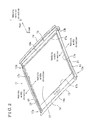
- Fig. 2 is a perspective view of the sunshade apparatus according to the first embodiment in a closed state
- Fig. 3 is a partial plan view that illustrates an outward portion of the sunshade apparatus in the vehicle width direction according to the first embodiment
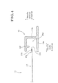
- Fig. 4 is a cross-sectional view of the sunshade apparatus according to the first embodiment taken along a line IV-IV in Fig. 3 vertically in vehicle front and rear directions;
- Fig. 5 is a partial perspective view of the sunshade apparatus according to the first embodiment that illustrates a retracting unit
- Fig. 6 is a partial plan view that illustrates an outward portion of the sunshade apparatus in the vehicle width direction according to the second embodiment
- Fig. 7 is a cross-sectional view of the sunshade apparatus according to the second embodiment taken along a line VII-VII in Fig. 6 vertically in the vehicle front and rear directions;
- Fig. 8 is a cross-sectional view of the sunshade apparatus according to the second embodiment taken along a line VII-VII in Fig. 6 vertically in the vehicle front and rear directions.
- a first embodiment of a sunshade apparatus 11 (serving as a sunshade apparatus for a vehicle) will be described as follows.
- Fig. 1 illustrates a perspective view of a roof 1 of a vehicle in which the sunshade apparatus 11 according to the first embodiment will be installed.
- a roof panel 2 that forms the roof 1 includes a light transmitting portion 3, which is installed with a transparent panel 4 made of transparent glass, resin, or other similar material, to take in sunlight.
- An outer periphery portion 4a of the transparent panel 4 is treated with a sealing member for a purpose of preventing rainwater to enter a vehicle compartment.
- the sunshade apparatus 11 illustrated in Fig. 2 is installed to a surface on a vehicle compartment side 2a near side edges 3a of a light transmitting portion of the roof panel to take in or shield sunlight by opening or closing the sunshade apparatus 11.
- Fig. 2 is a perspective view of the sunshade apparatus 11 in a closed state according to the first embodiment.
- Guide rails 13 each of which is extending in vehicle front and rear directions 12a, 12b (equivalent to shading sheet opening-closing directions) and opposing to each other in the vehicle width directions 14a, 14b (equivalent to opposing directions), are positioned to the surface 2a on the vehicle compartment side of the roof panel 2.
- Each of the guide rails 13 is curved to fit the shape of the roof panel 2 and is connected to each other by a front frame 15 and a rear frame 16, both of which are extending in the vehicle width directions 14a, 14b, at a front end portion 13a and at a rear end portion 13b respectively.
- Each of the guide rails 13 is produced by extrusion of aluminum or similar material and each frame 15, 16 is produced by pressing a steel plate or similar material into a shape.
- the rear frame 16 rotationally supports a retracting unit 18 (serving as a winding member), which winds a shading sheet 17 about a rotation axis in the vehicle width directions 14a, 14b.
- the retracting unit 18 includes a core portion 18a extending in the vehicle width directions 14a, 14b.
- a rear edge portion 17a positioned at a rear portion of the shading sheet 17 is retained at the core portion 18a.
- a front edge portion 17b positioned at a front portion of the shading sheet 17 has a garnish 19 (serving as a moving member) attached thereto and the garnish 19 moves along the guide rails13 in the vehicle front and rear directions 12a, 12b.
- the garnish 19 is equipped with an operating portion 19a, which serves as a handle for operation.
- Each of side edge portions 17c (serving as edge portions) arranged in the vehicle width directions 14a, 14b of the shading sheet 17 is retained by a corresponding wire 21 (serving as a holding member) stretched in the vehicle front and rear directions 12a, 12b.
- the shading sheet 17 is weaved by using a nylon fiber or other similar material to have an approximately 0.4 mm thickness.
- Each of the wires 21 is formed to be approximately 0.4 mm in diameter by using a para-aramid resin (e.g. KevlarR) or similar material having a low frictional coefficient and high tensile strength.
- Fig. 3 is a partial plan view that illustrates an outward portion of the sunshade apparatus 11 in the vehicle width direction 14b of the according to the first embodiment.
- the rear edge portion 17a of the shading sheet 17 is retained by the core portion 18a of the retracting unit 18 together with a root portion 21a of each wire 21.
- the root portion 21a of each wire 21 may be retained by the core portion 18a of the retracting unit 18 via the shading sheet 17.
- a holding portion 21b which is at a position in the vehicle front direction 12a with respect to the root portion 21a of each wire 21, retains the shading sheet 17 by engaging to the corresponding side edge portion 17c of the shading sheet 17.
- Each of garnish end portions 19b (serving as both ends in opposing directions 19b), which is positioned outwardly in the vehicle width direction 14b of the garnish 19, includes a pillar portion 19c formed to project in vehicle upward-downward directions 22a, 22b.
- Each of the pillar portions 19c is positioned inwardly in the vehicle width direction 14a with respect to the corresponding wire 21.
- winding of the wire 21 starts from outwardly in the vehicle width direction 14b and wound around the pillar portion 19c toward vehicle rear direction 12b, then folded back toward outwardly for the vehicle width direction 14b and pulled out in vehicle front direction 12a.
- each wire 21 is engaged to the corresponding pillar portion 19c by being wound around the pillar portion 19c in an winding method known as an alpha winding.
- a cooperating portion 21 d a portion on each wire 21 positioned next to the locking portion 21c in the vehicle front direction 12a, changes moving direction along a guide roller 23 (serving as a direction change member) positioned at the front end portion 13a of the guide rail 13.
- Each guide roller 23 having a rotation axis in vehicle upward-downward directions 22a, 22b is rotationally positioned at the corresponding front end portion 13a.
- the cooperating portion 21d on each of the wires 21 is wound around the corresponding guide roller 23 horizontally and folded back outwardly in the vehicle width direction 14b to change the moving direction in the vehicle rear direction 12b.
- the cooperating portion 21d on each of the wires 21 moving toward the vehicle rear direction 12b contacts a guiding portion 13c (serving as a guiding member), which is formed to project in the vehicle upward direction 22a at the rear end portion 13b of the guide rail 13, to be guided so that a cooperating edge portion 21e of the cooperating portion 21 d is retained to the wire winding portion 18b (serving as a winding member portion) of the retracting unit 18.
- Fig. 4 is a cross-sectional view of the sunshade apparatus 11 according to the first embodiment taken along a line IV-IV in Fig. 3 vertically in the vehicle front and rear directions 12a, 12b.
- Each of the guide rails 13 includes a side wall portion 13e, which extends in the vehicle upward direction 22a from a lower frame portion 13d, which extends in the vehicle width directions 14a, 14b, and an upper frame portion 13f, which extends inwardly in the vehicle width direction 14a from an edge of the side wall portion 13e in the vehicle upward direction 22a.
- Each of the side edge portions 17c of the shading sheet 17 is folded inwardly in the vehicle width direction 14a at each of the folded portions 17d extending in the vehicle front and rear directions 12a, 12b, to enfold each of the holding portion 21 b, then sewn at a position inwardly in the vehicle width direction 14a with respect to the folded portion 17d in a manner to avoid the corresponding holding portion 21 b being sewn-in.
- the shading sheet 17 is retained to the wires 21 by the holding portions 21 b being enfolded by the side edge portions 17c.
- each of the cooperating portions 21d which is folded back at the corresponding guide roller 23, is positioned outwardly in the vehicle width direction 14b on a same horizontal level or on an offset level in the vehicle upward-downward directions 22a, 22b.
- Each folded portion 17d is positioned to overlap with the corresponding upper frame portion 13f and the lower frame portion 13d in the vehicle upward-downward directions 22a, 22b to be inconspicuous.
- each of the wires 21 engages to the shading sheet 17 at the holding portion 21 b, the portion of the corresponding wire 21 positioned inwardly in the vehicle width direction 14a.
- Fig. 5 is a partial perspective view of the sunshade apparatus 11 for the vehicle according to the first embodiment that illustrates the retracting unit 18 of the sunshade apparatus 11.
- the retracting unit 18 includes the cylindrical core portion 18a, which extends in the vehicle width directions 14a, 14b, and wire winding portions 18b, each of which fits into the corresponding core portion edge 18c that is positioned at the ends in the vehicle width directions 14a, 14b of the core portion 18a.
- the core portion 18a internally contains torsion springs 24 (serving as a biasing member), which is for biasing the retracting unit 18.
- the core portion 18a retains the rear edge portion 17a of the shading sheet and the root portions 21 a of the wires 21.
- Each of the wire winding portions 18b retains a cooperating edge portion 21e of the corresponding wire 21.
- Each of the wire winding portions 18b which is a conical portion with a diameter thereof becoming smaller toward outwardly in the vehicle width direction 14b, includes a spirally formed winding groove 18d to wind the corresponding wire 21 in a line.
- Each of the wire winding portions 18b includes a bearing portion 18e defined outwardly in the vehicle width direction 14b at an end thereof.
- Each of the bearing portions 18e rotationally supports the retracting unit 18 by fitting to a corresponding shaft retaining portion 16a defined outwardly in the vehicle width direction 14b at an end of the rear frame 16.
- Each of the wire winding portions 18b includes a cylindrical fitting portion 18f formed to extend inwardly in the vehicle width direction 14a and fits to the inner periphery of the core portion 18a to retain the core portion 18a to coaxially rotate and in a relative rotation with the wire winding portions 18b.
- An end of each torsion spring 24, which is internally contained in the core portion 18a, is engaged to the core portion 18a and the other end is engaged to the fitting portion 18f.
- the torsion springs 24 bias the core portion 18a in a rotating direction 25a for opening the shading sheet 17 and the wire winding portion 18b in a rotating direction 25b for closing the shading sheet 17 to consistently provide a tension on the wires 21.
- each guide rail13 includes the guiding portion 13c extending in the vehicle upward direction 22a.
- Each of the guiding portions 13c includes a guiding groove 13g circumferentially provided around the surface extending in the vehicle upward-downward directions 22a, 22b.
- Each of the wires 21 contacts the guiding groove13g of the corresponding guiding portion 13c and is biased inwardly in the vehicle width directions 14a and in the vehicle downward direction 22b.
- each of the cooperating portions 21d is pulled via the locking portion 21 c, which is engaged to the pillar portion 19c, and moves in the vehicle rear direction 12b. Meanwhile, a portion close to the wire winding portion 18b on each of the cooperating portions 21 d, moves in the vehicle front direction 12a and rotates the corresponding guide roller 23 in the direction of the movement and changes the direction of the movement along the guide roller 23.
- the diameter at the wound off portion increases because the wound off portion of the cooperating portion 21d moves inwardly in the vehicle width direction 14a along the spiral formed on each winding portion 18b and also because the cone angle of each wire winding portion 18b is defined so that diameters of the retracted portion and the wound off portion are consistently equal to each other.
- the diameter of the retracted portion during the opening operation of the sunshade apparatus 11 includes the thickness of the shading sheet 17 and the thickness of the holding portions 21 b wound around the core portion 18a and measured at the outer periphery.
- the diameter at the wound off portion is the outer diameter measured at the position that the cooperating portion 21d is wound off from the wire winding portion 18b.
- the relationship of the diameters of the retracted portion and the wound off portion and the portions associated to the retraction and winding off for example the core portion 18a and wire winding portions 18b are switched.
- the diameter of the retracted portion and the wound off portion being equal to each other and the tensional forces provided to the wires 21 at the retracted portion and the wound off portion being equal to each other, a torque exerted on the core portion 18a and the wire winding portions18b is consistently balanced while the shading sheet 17 is at rest.
- the garnish 19 includes the pillar portions 19c that engage the wires 21 at the positions inwardly in the vehicle width direction 14a with respect to each of the wires 21, force components of the tensional forces act outwardly in the vehicle width direction 14b on the garnish 19.
- the garnish 19 which is consistently centered, slides in the vehicle front and rear directions 12a, 12b without contacting the guide rails 13 and stops by contacting the guiding portions 13c functioning as stoppers.
- each member involved for the closing operation operates in a reverse direction for the opening operation.
- the garnish 19 is moved in the vehicle front direction 12a
- the shading sheet 17 and the holding portions 21 b are wound off from the core portion 18a and the retracting unit 18 rotates in the rotating direction 25b for closing the shading sheet 17.
- Each of the cooperating portion 21d is wound around the corresponding wire winding portion 18b in a line along the winding groove 18d, by being in contact with the guiding groove 13g of the corresponding guiding portion 13c and biased inwardly in the vehicle width direction 14a and in the vehicle downward direction 22b.
- the diameter at each wound portion becomes smaller and the winding position moves outwardly in the vehicle width direction 14b.
- the first embodiment is effective on achieving following results.
- the sunshade apparatus 11 retains the shading sheet 17 at a desired position by the tensional force balanced in the vehicle front and rear directions 12a, 12b being applied to the shading sheet 17 via the wires 21 and the garnish 19. Therefore, while retaining the shading sheet 17 at a desired position, the operational force for opening or closing the shading sheet 17 is decreased compared to when a position of the garnish 19 is retained by a frictional force against a biasing force in the closing direction, which requires the operational force against such frictional force when moving the garnish 19.
- Retaining of the shading sheet 17 at the desired position is more stable with the aforementioned method of applying the balanced tensional force to the wires 21 compared to the method which uses the frictional force, which is being more susceptible to vibrations that cause a decrease in stability of the biasing force for retaining the shading sheet 17.
- an embodiment of the sunshade apparatus 11 disclosed here is further applied to SUVs and vehicles for developing countries, which are likely to be driven on non-paved roads.
- the shading sheet 17 is retained at both side edge portions 17c by the wires 21 with the tensional force in vehicle upward-downward directions 22a, 22b, the slacking that may occur at the middle portion 13h of the shading sheet 17 is decreased compared to when the shading sheet 17 is retained by the garnish 19 alone.
- a thickness of each of the holding members is reduced, which in turn reduces a radius of the retracting unit 18 when the shading sheet 17 is retracted, which in turn reduces a protruding amount of the sunshade apparatus 11 in the vehicle upward-downward directions 22a, 22b toward a vehicle interior, which results in providing more room to a person in the vehicle for more comfort.
- each of the wires 21 is free from the restriction of the shading sheet 17 so that each of the wires 21 maintains a straight line form with less effort, or maintains the tension with less force. Requiring less tensional force requires a lower setting of a spring constant for the torsion spring 24.
- a lighter or less strength material may be used to form the retracting unit 18 to reduce the weight of the sunshade apparatus 11 as a whole.
- each of the wires 21 is guided to fold back outwardly in the vehicle width direction 14b with the corresponding guide roller 23 so that the holding portion 21b and the cooperating portion 21d are aligned in parallel. Therefore, the overlapping of holding portions 21b and the cooperating portions 21d in the vehicle upward-downward directions 22a, 22b is avoided and the thickness of the sunshade apparatus 11 is reduced.
- the locking portion 21c of each of the wires 21 is engaged to the corresponding pillar portion 19c at both garnish end portions 19b by being wound in an winding method known as the alpha winding, so that the wires 21 are biased to be balanced both in vehicle front and rear directions 12a, 12b and the vehicle width directions 14a, 14b. Therefore, shoes or other members required for centering the shading sheet 17 are made unnecessary, and in addition, frictional forces available for opening or closing the shading sheet 17 when sliding shoes or other members are suppressed at the same time, thus the operational force is reduced.
- the diameter at the wire winding portions 18b, which winds in or winds off the wires 21, is changed according to the length of the wound wires 21 to equal with the diameter at the core portion 18a of the shading sheet 17, so that a torque exerted on the retracting unit 18 is equilibrated, thus operational force of the sunshade apparatus 11 is reduced.
- the guiding portions 13c guiding the cooperating portion 21d of the corresponding wire 21 with a biasing force inwardly in the vehicle width direction 14a winding accuracy at the wire winding portion 18b is controlled and the cooperating portion 21d are wound in a line without becoming loose.
- a second embodiment of a sunshade apparatus 11 will be described as follows.
- Fig. 6 is a partial plan view that illustrates the outward portion of the sunshade apparatus 11 in the vehicle width direction according to the second embodiment.
- Each of the root portions 21 a which is a rear end of the holding portion 21 b of each wire 21, is retained by the core portion 18a of the retracting unit 18 (or the rear end is supported by the retracting unit 18 in a wound state), and the front end portion 13a of the holding portion 21 b of the wire 21 is supported to the pillar portion 19c in a wound state.
- the holding portion 21 b of the wire 21 is provided with a tensional force.
- the first embodiment provides support of the shading sheet 17 at the front and rear end of the holding portion 21b alone. In this condition, the holding portion 21b may be pulled inwardly in the vehicle width direction 14a by a weight of the shading sheet 17, especially during the shading sheet 17 is in a closed state.
- the shape of each of the guide rails 13 is partially modified in the second embodiment.
- Fig. 7 is a cross-sectional view of the sunshade apparatus 11 according to the second embodiment taken along a line VII-VII in Fig. 6 vertically in the vehicle front and rear direction.
- Fig. 8 is a cross-sectional view of the sunshade apparatus 11 according to the second embodiment taken along a line VIII-VIII in Fig. 6 vertically in the vehicle front and rear direction.
- each of the guide rails 13 includes the lower frame portion 13d, the side wall portion 13e, the upper frame portion 13f and a slanted portion 13A (serving as a contact portion).
- each of the side wall portions 13e extends in the vehicle upward direction 22a from each of the lower frame portions 13d, which extends in the vehicle width directions 14a, 14b and each of the upper frame portions 13f extends inwardly in the vehicle width direction 14a from an edge for the vehicle upward direction 22a of each side wall portion 13e.
- each of the slanted portions 13A extends from an edge at inwardly in the vehicle width direction 14a of each lower frame portion 13d toward a direction which is inwardly in the vehicle width direction 14a and the vehicle upward direction 22a (i.e., bent in the vehicle upward direction 22a, which is different from a direction inwardly in the vehicle width direction 14a).
- each of the side edge portions 17c of the shading sheet 17 is folded inwardly in the vehicle width direction 14a at each of the folded portions 17d extending in the vehicle front and rear directions 12a, 12b, to enfold each of the holding portions 21 b, then sewn at a stitching position S (indicated with an alternate long and short dash line in Figs. 7 and in Fig. 8 ), which is a position inwardly in the vehicle width direction 14a relative to each of the folded portions 17d, in a manner to avoid the corresponding holding portion 21 b being sewn-in.
- the shading sheet 17 is retained to the wires 21 by the holding portions 21 b being enfolded by the side edge portions 17c.
- each of the slanted portions 13A biases the holding portion 21 b of the corresponding wire 21 and the shading sheet 17 outwardly in the vehicle width direction 14b by being in contact with the corresponding side edge portion 17c.
- each of the slanted portions 13A is a slanted surface that generates a force component outwardly in the vehicle direction 14b when a force is applied in the vehicle upward-downward directions 22a, 22b.
- each of the root portions 21 a which is the rear end portion 13b of the holding portion 21b of each wire 21, is retained to the core portion 18a of the retracting unit 18 (or the rear end portion 13b is retained to the retracting unit 18 by being rolled in) and each of the front end portions 13a of the holding portion 21b of each wire 21 is retained by being wound around the corresponding pillar portion 19c.
- each of the holding portions 21 b is conditioned to take the shortest route between the supporting portions at the front end and the rear end.
- each of the guide rails 13 is curved in a manner so that middle portion in the vehicle front and rear directions 12a, 12b is projecting in the vehicle upward direction 22a.
- an area of the edge portion 17c of the shading sheet 17 that interact with the corresponding slanted portion 13A is established to be larger at a middle portion 13h in the vehicle front and rear directions 12a, 12b (as illustrated in Fig. 7 with an alternate long and two short dashes line and in Fig. 8 ), relative to the area at the front end portion 13a and rear end portion 13b (serving as both end portions) in the vehicle front and rear directions 12a, 12b (refer to Fig. 7 ).
- the alternate long and two short dashes line in Fig. 7 indicates the edge portion 17c of the shading sheet 17 illustrated in Fig. 8 .
- An end portion 13B positioned in the vehicle upward direction 22a of each of the slanted portion 13A is chamfered for avoiding a sharp edge damaging the shading sheet 17. Further, the shading sheet 17 contacts the end portion 13B at a position outwardly in the vehicle width direction 14b relative to the stitching position S throughout the operation of the shading sheet 17. Therefore, cutting of the stitching member, for example a stitching thread, which is used to stitch the shading sheet 17, is avoided. When a strong enough stitching member is used, the stitching position S may be positioned to interact with the end portion 13B.
- the shading sheet 17, which contacts the slanted portion 13A of each of the guide rails 13, is formed of a material having a good sliding characteristic.
- a sliding characteristic may be improved by coating the side edge portion 17c that contacts the slanted portion 13A with a resin and other materials.
- the second embodiment is effective on achieving following results in addition to the aforementioned results described for the first embodiment.
- the slanted portions 13A bias the wires 21 and the shading sheet 17 outwardly in the vehicle width direction 14b to generate tensional forces, so that, while reducing the width required for the holding members by using wires, slacking of the shading sheet 17 is controlled favorably.
- the guide rails 13 are curved to project in the vehicle upward direction 22a for providing a larger area of the side edge portion 17c of the shading sheet 17 which interacts with the corresponding slanted portions 13A at the middle portion 13h in the vehicle front and rear directions 12a, 12b where more slacking of the shading sheet 17 may occur compared to the area at the front end portion 13a and rear end portion 13b.
- the wires 21, which form the holding members in the aforementioned embodiments, may be formed by belts, chains, or similar.
- the locking portions 21 c of the wires 21, which are wound around the pillar portions 19c of the garnish end portions 19b in an winding method known as the alpha winding in the aforementioned embodiments, may be engaged to the pillar portions 19b by hooking or methods other than winding.
- the garnish 19, which is retained to the wires 21 and the tensional forces thereof in the aforementioned embodiments, may be additionally retained to the guide rails 13 by providing separate shoes or similar retaining members.
- the wire 21, which is provided with the tensional force with the torsion springs 21 in the aforementioned embodiments, may be provided with the tensional force by being formed with an elastic material as a whole or in part.
- the side edge portions 17c of the shading sheet 17, which are retained by the holding portions 21 b of the wires 21 being enfolded by the side edge portions 17c in the aforementioned embodiments, may be integrated with the holding portions 21b by adhesion, welding, stitching or by other methods, or may be integrally formed with the holding portions 21 b.
- the sunshade apparatus 11 which is opened and closed manually in the aforementioned embodiments, may be operated by an additional separate motor or other mechanism to rotate the retracting unit 18 and the garnish 19 may be moved in parallel by using a rack belt or other members. Because the tensional forces of the wires 21 stably keep an opening amount of the sunshade apparatus 11, an application of a worm gear or similar mechanism to prevent reverse rotation in the closing direction is unnecessary. By considering causes for lowering power transmission efficiency, for example worm gear slip or other similar causes, a necessary motor driving power is kept small.
- each of the slanted portions 13A which is formed with a flat surface in the aforementioned embodiments, may be formed with a curved surface or other shapes that generates a force component.
- the sunshade apparatus 11 decreases an operational force for opening or closing the shading sheet 17, retains the shading sheet 17 at a desired position, and at the same time decreases a slacking that may occur at the middle portion 13h of the shading sheet 17.
Landscapes
- Engineering & Computer Science (AREA)
- Mechanical Engineering (AREA)
- Building Awnings And Sunshades (AREA)
- Operating, Guiding And Securing Of Roll- Type Closing Members (AREA)
- Tents Or Canopies (AREA)
Applications Claiming Priority (2)
| Application Number | Priority Date | Filing Date | Title |
|---|---|---|---|
| JP2010248001 | 2010-11-05 | ||
| JP2011069814A JP5884281B2 (ja) | 2010-11-05 | 2011-03-28 | 車両用サンシェード |
Publications (3)
| Publication Number | Publication Date |
|---|---|
| EP2450209A2 true EP2450209A2 (de) | 2012-05-09 |
| EP2450209A3 EP2450209A3 (de) | 2012-06-13 |
| EP2450209B1 EP2450209B1 (de) | 2013-12-25 |
Family
ID=45033757
Family Applications (1)
| Application Number | Title | Priority Date | Filing Date |
|---|---|---|---|
| EP11187512.6A Revoked EP2450209B1 (de) | 2010-11-05 | 2011-11-02 | Sonnenschutzvorrichtung für Fahrzeuge |
Country Status (4)
| Country | Link |
|---|---|
| US (1) | US8770258B2 (de) |
| EP (1) | EP2450209B1 (de) |
| JP (1) | JP5884281B2 (de) |
| CN (1) | CN102555743B (de) |
Cited By (5)
| Publication number | Priority date | Publication date | Assignee | Title |
|---|---|---|---|---|
| GB2491441A (en) * | 2011-05-31 | 2012-12-05 | Gm Global Tech Operations Inc | A restraining arrangement for a shading system for a motor vehicle |
| EP3017985A1 (de) * | 2014-11-06 | 2016-05-11 | Inalfa Roof Systems Group B.V. | Flexibler Sonnenschutz |
| WO2018115365A1 (fr) * | 2016-12-22 | 2018-06-28 | Advanced Comfort Systems France Sas - Acs France | Dispositif d'occultation pour pavillon de vehicule automobile, a elements de maintien et de guidage de la toile renforces, pavillon et procede de fabrication correspondants. |
| US12024001B2 (en) | 2019-08-27 | 2024-07-02 | Inalfa Roof Systems Group B.V. | Sunshade system and method of manufacturing parts thereof |
| US12590424B2 (en) * | 2022-04-22 | 2026-03-31 | Wirtgen Gmbh | Self-propelled earth working machine having a canopy variable in length in the longitudinal direction of the machine |
Families Citing this family (13)
| Publication number | Priority date | Publication date | Assignee | Title |
|---|---|---|---|---|
| US8757239B2 (en) * | 2008-08-26 | 2014-06-24 | Hunter Douglas Inc. | Roll-up retractable covering for architectural openings |
| JP2013252837A (ja) | 2012-06-08 | 2013-12-19 | Aisin Seiki Co Ltd | サンシェード装置 |
| DE102012219523B4 (de) * | 2012-10-25 | 2016-02-18 | Bos Gmbh & Co. Kg | Rollovorrichtung für ein Kraftfahrzeug |
| AT513942B1 (de) * | 2013-01-22 | 2017-11-15 | Htp High Tech Plastics Gmbh | Vorrichtung zur Abdeckung einer Sichtöffnung |
| KR101511557B1 (ko) * | 2013-12-09 | 2015-04-13 | 현대자동차주식회사 | 이중 롤러를 이용한 롤블라인드 구조 |
| DE102015101934A1 (de) * | 2014-02-12 | 2015-08-13 | Inteva Products, Llc | Heckscheibensonnenblende für Fahrzeug und Verfahren zum Betrieb |
| CN104097492B (zh) * | 2014-08-14 | 2016-04-13 | 沈太平 | 小汽车固定型电动多功能遮阳架 |
| JP6517646B2 (ja) * | 2015-09-24 | 2019-05-22 | アイシン精機株式会社 | シェード装置 |
| US10969255B2 (en) * | 2018-04-20 | 2021-04-06 | Darrel Eugene Self | TIC environmental event sensor |
| DE102018116346A1 (de) * | 2018-07-05 | 2020-01-09 | Webasto SE | Abschattungsvorrichtung |
| DE102021203516B4 (de) * | 2021-04-09 | 2025-06-18 | Bos Gmbh & Co. Kg | Wickelanordnung und Verfahren zur Herstellung einer solchen Wickelanordnung |
| JP7219835B1 (ja) * | 2022-03-28 | 2023-02-08 | 八千代工業株式会社 | 車両のルーフモジュール |
| JP7699270B1 (ja) * | 2024-05-10 | 2025-06-26 | マザーサンヤチヨ・オートモーティブシステムズ株式会社 | サンシェード装置 |
Citations (2)
| Publication number | Priority date | Publication date | Assignee | Title |
|---|---|---|---|---|
| JP2000272341A (ja) | 1999-03-11 | 2000-10-03 | Webasto Japan Kk | 車両ルーフのローラーブライド式サンシェード |
| US6874845B2 (en) | 2002-08-29 | 2005-04-05 | Webasto Vehicle Systems International Gmbh | Shade tarp as sun shield |
Family Cites Families (23)
| Publication number | Priority date | Publication date | Assignee | Title |
|---|---|---|---|---|
| US262398A (en) * | 1882-08-08 | gxraed | ||
| US3180401A (en) * | 1962-03-02 | 1965-04-27 | Thomas F Gambon | Shade |
| US3386489A (en) * | 1965-04-15 | 1968-06-04 | Benton Williams Company Inc | Closure apparatus |
| US3768540A (en) * | 1971-06-17 | 1973-10-30 | Swain T Mc | Retractible canopy shelter |
| US4596093A (en) * | 1983-01-04 | 1986-06-24 | Four Seasons Solar Products Corporation | Structural element especially suitable for solar greenhouses and the like and particularly for controlled shading |
| DE10122570C1 (de) * | 2001-05-09 | 2002-07-25 | Webasto Vehicle Sys Int Gmbh | Sonnenrollo für ein Fahrzeugdach |
| DE10232536B4 (de) * | 2002-07-18 | 2004-09-30 | Philipp Tussinger | Rollovorrichtung |
| DE102004020336C5 (de) * | 2004-04-26 | 2008-09-18 | Webasto Ag | Fahrzeudach mit einer Rolloanordnung |
| DE102004046783A1 (de) * | 2004-09-27 | 2006-04-06 | Webasto Ag | Rolloanordnung für ein Kraftfahrzeug |
| DE102004049167A1 (de) | 2004-10-08 | 2006-04-20 | Hs Products Engineering Gmbh | Fensterrollo für ein Fahrzeugfenster |
| JP4153917B2 (ja) * | 2005-03-22 | 2008-09-24 | 本田技研工業株式会社 | サンシェード装置 |
| DE202005006415U1 (de) * | 2005-04-21 | 2005-06-23 | Arvinmeritor Gmbh | Baugruppe mit einem Rollo |
| DE102005040758B4 (de) | 2005-08-26 | 2010-09-23 | Webasto Ag | Rolloanordnung |
| DE102005048207B3 (de) | 2005-10-07 | 2006-11-23 | Webasto Ag | Rolloanordnung für ein Kraftfahrzeug |
| DE102006035632B4 (de) * | 2006-07-31 | 2012-08-02 | Webasto Ag | Rolloanordnung für ein Fahrzeugdach |
| EP1908616B1 (de) * | 2006-10-06 | 2013-04-17 | Inalfa Roof Systems Group B.V. | Sonnenblende und Schiebedachkonstruktion mit solch einer Sonnenblende |
| DE102007041298B4 (de) * | 2007-08-31 | 2010-06-10 | Webasto Ag | Rolloanordnung für ein Kraftfahrzeug |
| EP2058158B1 (de) * | 2007-11-06 | 2011-06-15 | Inalfa Roof Systems Group B.V. | Spannvorrichtung und damit ausgerüstete Rolloanordnung |
| EP2093086A1 (de) * | 2008-02-25 | 2009-08-26 | Inalfa Roof Systems Group B.V. | Sonnenschutzanordnung und damit ausgestattete, offene Dachkonstruktion |
| US7568752B1 (en) * | 2008-03-04 | 2009-08-04 | Macauto Industrial Co., Ltd. | Sunshade assembly |
| JP4724221B2 (ja) * | 2008-12-12 | 2011-07-13 | 八千代工業株式会社 | ロールサンシェード装置 |
| EP2393683B1 (de) * | 2009-02-04 | 2013-01-02 | Inalfa Roof Systems Group B.V. | Sonnenschutzanordnung |
| IT1400655B1 (it) | 2010-06-30 | 2013-06-28 | Azionaria Costruzioni Acma Spa | Macchina e metodo di confezionamento di materiale in fibra. |
-
2011
- 2011-03-28 JP JP2011069814A patent/JP5884281B2/ja not_active Expired - Fee Related
- 2011-09-23 US US13/200,349 patent/US8770258B2/en not_active Expired - Fee Related
- 2011-11-02 EP EP11187512.6A patent/EP2450209B1/de not_active Revoked
- 2011-11-04 CN CN201110351006.XA patent/CN102555743B/zh not_active Expired - Fee Related
Patent Citations (2)
| Publication number | Priority date | Publication date | Assignee | Title |
|---|---|---|---|---|
| JP2000272341A (ja) | 1999-03-11 | 2000-10-03 | Webasto Japan Kk | 車両ルーフのローラーブライド式サンシェード |
| US6874845B2 (en) | 2002-08-29 | 2005-04-05 | Webasto Vehicle Systems International Gmbh | Shade tarp as sun shield |
Cited By (8)
| Publication number | Priority date | Publication date | Assignee | Title |
|---|---|---|---|---|
| GB2491441A (en) * | 2011-05-31 | 2012-12-05 | Gm Global Tech Operations Inc | A restraining arrangement for a shading system for a motor vehicle |
| EP3017985A1 (de) * | 2014-11-06 | 2016-05-11 | Inalfa Roof Systems Group B.V. | Flexibler Sonnenschutz |
| US10132117B2 (en) | 2014-11-06 | 2018-11-20 | Inalfa Roof Systems Group B.V. | Flexible sunscreen and sunshade assembly provided therewith |
| US11414925B2 (en) | 2014-11-06 | 2022-08-16 | Inalfa Roof Systems Group B.V. | Flexible sunscreen and sunshade assembly provided therewith |
| WO2018115365A1 (fr) * | 2016-12-22 | 2018-06-28 | Advanced Comfort Systems France Sas - Acs France | Dispositif d'occultation pour pavillon de vehicule automobile, a elements de maintien et de guidage de la toile renforces, pavillon et procede de fabrication correspondants. |
| FR3061089A1 (fr) * | 2016-12-22 | 2018-06-29 | Advanced Comfort Systems France Sas - Acs France | Dispositif d'occultation pour pavillon de vehicule automobile, a elements de maintien et de guidage de la toile renforces, et pavillon correspondant |
| US12024001B2 (en) | 2019-08-27 | 2024-07-02 | Inalfa Roof Systems Group B.V. | Sunshade system and method of manufacturing parts thereof |
| US12590424B2 (en) * | 2022-04-22 | 2026-03-31 | Wirtgen Gmbh | Self-propelled earth working machine having a canopy variable in length in the longitudinal direction of the machine |
Also Published As
| Publication number | Publication date |
|---|---|
| JP5884281B2 (ja) | 2016-03-15 |
| CN102555743B (zh) | 2015-04-15 |
| US8770258B2 (en) | 2014-07-08 |
| EP2450209B1 (de) | 2013-12-25 |
| CN102555743A (zh) | 2012-07-11 |
| JP2012111477A (ja) | 2012-06-14 |
| EP2450209A3 (de) | 2012-06-13 |
| US20120111511A1 (en) | 2012-05-10 |
Similar Documents
| Publication | Publication Date | Title |
|---|---|---|
| EP2450209B1 (de) | Sonnenschutzvorrichtung für Fahrzeuge | |
| JP5391165B2 (ja) | 車両のロールシェード装置 | |
| US7051781B2 (en) | Sunshade assembly for a vehicle roof | |
| US7828041B2 (en) | Manually activated roll-up window shade | |
| US8393380B2 (en) | Roll-up shade apparatus for a vehicle | |
| US7581775B2 (en) | Side window roller blind | |
| KR20080086388A (ko) | 힌지 연결된 인장 로드 및 직각의 지지 로드를 포함하는측면 윈도우 롤러 블라인드 | |
| JP5975712B2 (ja) | ロールシェード装置 | |
| KR101263429B1 (ko) | 싱크로 벨트가 구비된 자동차용 롤러 블라인드 | |
| US20120145339A1 (en) | Vehicular shade assembly | |
| JP2010143327A (ja) | 車両のシェード装置 | |
| CN214420189U (zh) | 一种遮阳帘装置及车窗总成 | |
| KR20170072934A (ko) | 자동차 창문용 차양 장치 | |
| CN110733317B (zh) | 卷帘组件 | |
| EP2093086A1 (de) | Sonnenschutzanordnung und damit ausgestattete, offene Dachkonstruktion | |
| US20070267898A1 (en) | Sun Screen Device Suitable for Large Sunroofs | |
| JP6018784B2 (ja) | ロールシェード装置 | |
| KR101243359B1 (ko) | 핸들샤프트가 구비된 자동차용 롤러 블라인드 | |
| EP4019305B1 (de) | Dachsystem für ein fahrzeug mit einer sonnenblendenanordnung | |
| CN115038602A (zh) | 车顶上的卷帘装置 | |
| US20250332894A1 (en) | Roller blind assembly | |
| KR101509652B1 (ko) | 자동차용 롤러 블라인드 | |
| KR100512126B1 (ko) | 자동차의 가변 차양장치 | |
| FR2989637A1 (fr) | Dispositif d'occultation pour vehicule automobile |
Legal Events
| Date | Code | Title | Description |
|---|---|---|---|
| PUAI | Public reference made under article 153(3) epc to a published international application that has entered the european phase |
Free format text: ORIGINAL CODE: 0009012 |
|
| AK | Designated contracting states |
Kind code of ref document: A2 Designated state(s): AL AT BE BG CH CY CZ DE DK EE ES FI FR GB GR HR HU IE IS IT LI LT LU LV MC MK MT NL NO PL PT RO RS SE SI SK SM TR |
|
| AX | Request for extension of the european patent |
Extension state: BA ME |
|
| PUAL | Search report despatched |
Free format text: ORIGINAL CODE: 0009013 |
|
| AK | Designated contracting states |
Kind code of ref document: A3 Designated state(s): AL AT BE BG CH CY CZ DE DK EE ES FI FR GB GR HR HU IE IS IT LI LT LU LV MC MK MT NL NO PL PT RO RS SE SI SK SM TR |
|
| AX | Request for extension of the european patent |
Extension state: BA ME |
|
| RIC1 | Information provided on ipc code assigned before grant |
Ipc: B60J 7/00 20060101AFI20120508BHEP Ipc: B60J 1/20 20060101ALI20120508BHEP |
|
| 17P | Request for examination filed |
Effective date: 20121206 |
|
| GRAP | Despatch of communication of intention to grant a patent |
Free format text: ORIGINAL CODE: EPIDOSNIGR1 |
|
| RIC1 | Information provided on ipc code assigned before grant |
Ipc: B60J 1/20 20060101ALI20130514BHEP Ipc: B60J 7/00 20060101AFI20130514BHEP |
|
| INTG | Intention to grant announced |
Effective date: 20130611 |
|
| GRAS | Grant fee paid |
Free format text: ORIGINAL CODE: EPIDOSNIGR3 |
|
| GRAA | (expected) grant |
Free format text: ORIGINAL CODE: 0009210 |
|
| AK | Designated contracting states |
Kind code of ref document: B1 Designated state(s): AL AT BE BG CH CY CZ DE DK EE ES FI FR GB GR HR HU IE IS IT LI LT LU LV MC MK MT NL NO PL PT RO RS SE SI SK SM TR |
|
| REG | Reference to a national code |
Ref country code: GB Ref legal event code: FG4D |
|
| REG | Reference to a national code |
Ref country code: CH Ref legal event code: EP |
|
| REG | Reference to a national code |
Ref country code: AT Ref legal event code: REF Ref document number: 646412 Country of ref document: AT Kind code of ref document: T Effective date: 20140115 |
|
| REG | Reference to a national code |
Ref country code: IE Ref legal event code: FG4D |
|
| REG | Reference to a national code |
Ref country code: DE Ref legal event code: R096 Ref document number: 602011004336 Country of ref document: DE Effective date: 20140213 |
|
| PG25 | Lapsed in a contracting state [announced via postgrant information from national office to epo] |
Ref country code: HR Free format text: LAPSE BECAUSE OF FAILURE TO SUBMIT A TRANSLATION OF THE DESCRIPTION OR TO PAY THE FEE WITHIN THE PRESCRIBED TIME-LIMIT Effective date: 20131225 Ref country code: FI Free format text: LAPSE BECAUSE OF FAILURE TO SUBMIT A TRANSLATION OF THE DESCRIPTION OR TO PAY THE FEE WITHIN THE PRESCRIBED TIME-LIMIT Effective date: 20131225 Ref country code: NO Free format text: LAPSE BECAUSE OF FAILURE TO SUBMIT A TRANSLATION OF THE DESCRIPTION OR TO PAY THE FEE WITHIN THE PRESCRIBED TIME-LIMIT Effective date: 20140325 Ref country code: SE Free format text: LAPSE BECAUSE OF FAILURE TO SUBMIT A TRANSLATION OF THE DESCRIPTION OR TO PAY THE FEE WITHIN THE PRESCRIBED TIME-LIMIT Effective date: 20131225 Ref country code: LT Free format text: LAPSE BECAUSE OF FAILURE TO SUBMIT A TRANSLATION OF THE DESCRIPTION OR TO PAY THE FEE WITHIN THE PRESCRIBED TIME-LIMIT Effective date: 20131225 |
|
| REG | Reference to a national code |
Ref country code: NL Ref legal event code: VDEP Effective date: 20131225 |
|
| REG | Reference to a national code |
Ref country code: AT Ref legal event code: MK05 Ref document number: 646412 Country of ref document: AT Kind code of ref document: T Effective date: 20131225 |
|
| REG | Reference to a national code |
Ref country code: LT Ref legal event code: MG4D |
|
| PG25 | Lapsed in a contracting state [announced via postgrant information from national office to epo] |
Ref country code: RS Free format text: LAPSE BECAUSE OF FAILURE TO SUBMIT A TRANSLATION OF THE DESCRIPTION OR TO PAY THE FEE WITHIN THE PRESCRIBED TIME-LIMIT Effective date: 20131225 Ref country code: LV Free format text: LAPSE BECAUSE OF FAILURE TO SUBMIT A TRANSLATION OF THE DESCRIPTION OR TO PAY THE FEE WITHIN THE PRESCRIBED TIME-LIMIT Effective date: 20131225 |
|
| PG25 | Lapsed in a contracting state [announced via postgrant information from national office to epo] |
Ref country code: BE Free format text: LAPSE BECAUSE OF FAILURE TO SUBMIT A TRANSLATION OF THE DESCRIPTION OR TO PAY THE FEE WITHIN THE PRESCRIBED TIME-LIMIT Effective date: 20131225 Ref country code: IS Free format text: LAPSE BECAUSE OF FAILURE TO SUBMIT A TRANSLATION OF THE DESCRIPTION OR TO PAY THE FEE WITHIN THE PRESCRIBED TIME-LIMIT Effective date: 20140425 Ref country code: EE Free format text: LAPSE BECAUSE OF FAILURE TO SUBMIT A TRANSLATION OF THE DESCRIPTION OR TO PAY THE FEE WITHIN THE PRESCRIBED TIME-LIMIT Effective date: 20131225 |
|
| PG25 | Lapsed in a contracting state [announced via postgrant information from national office to epo] |
Ref country code: PT Free format text: LAPSE BECAUSE OF FAILURE TO SUBMIT A TRANSLATION OF THE DESCRIPTION OR TO PAY THE FEE WITHIN THE PRESCRIBED TIME-LIMIT Effective date: 20140428 Ref country code: CZ Free format text: LAPSE BECAUSE OF FAILURE TO SUBMIT A TRANSLATION OF THE DESCRIPTION OR TO PAY THE FEE WITHIN THE PRESCRIBED TIME-LIMIT Effective date: 20131225 Ref country code: CY Free format text: LAPSE BECAUSE OF FAILURE TO SUBMIT A TRANSLATION OF THE DESCRIPTION OR TO PAY THE FEE WITHIN THE PRESCRIBED TIME-LIMIT Effective date: 20131225 Ref country code: ES Free format text: LAPSE BECAUSE OF FAILURE TO SUBMIT A TRANSLATION OF THE DESCRIPTION OR TO PAY THE FEE WITHIN THE PRESCRIBED TIME-LIMIT Effective date: 20131225 Ref country code: SK Free format text: LAPSE BECAUSE OF FAILURE TO SUBMIT A TRANSLATION OF THE DESCRIPTION OR TO PAY THE FEE WITHIN THE PRESCRIBED TIME-LIMIT Effective date: 20131225 Ref country code: AT Free format text: LAPSE BECAUSE OF FAILURE TO SUBMIT A TRANSLATION OF THE DESCRIPTION OR TO PAY THE FEE WITHIN THE PRESCRIBED TIME-LIMIT Effective date: 20131225 Ref country code: NL Free format text: LAPSE BECAUSE OF FAILURE TO SUBMIT A TRANSLATION OF THE DESCRIPTION OR TO PAY THE FEE WITHIN THE PRESCRIBED TIME-LIMIT Effective date: 20131225 Ref country code: RO Free format text: LAPSE BECAUSE OF FAILURE TO SUBMIT A TRANSLATION OF THE DESCRIPTION OR TO PAY THE FEE WITHIN THE PRESCRIBED TIME-LIMIT Effective date: 20131225 |
|
| REG | Reference to a national code |
Ref country code: DE Ref legal event code: R026 Ref document number: 602011004336 Country of ref document: DE |
|
| PLBI | Opposition filed |
Free format text: ORIGINAL CODE: 0009260 |
|
| PG25 | Lapsed in a contracting state [announced via postgrant information from national office to epo] |
Ref country code: DK Free format text: LAPSE BECAUSE OF FAILURE TO SUBMIT A TRANSLATION OF THE DESCRIPTION OR TO PAY THE FEE WITHIN THE PRESCRIBED TIME-LIMIT Effective date: 20131225 |
|
| PLAX | Notice of opposition and request to file observation + time limit sent |
Free format text: ORIGINAL CODE: EPIDOSNOBS2 |
|
| 26 | Opposition filed |
Opponent name: INALFA ROOF SYSTEMS GROUP B.V. Effective date: 20140924 |
|
| PG25 | Lapsed in a contracting state [announced via postgrant information from national office to epo] |
Ref country code: PL Free format text: LAPSE BECAUSE OF FAILURE TO SUBMIT A TRANSLATION OF THE DESCRIPTION OR TO PAY THE FEE WITHIN THE PRESCRIBED TIME-LIMIT Effective date: 20131225 |
|
| REG | Reference to a national code |
Ref country code: DE Ref legal event code: R026 Ref document number: 602011004336 Country of ref document: DE Effective date: 20140924 |
|
| PLAF | Information modified related to communication of a notice of opposition and request to file observations + time limit |
Free format text: ORIGINAL CODE: EPIDOSCOBS2 |
|
| PLBB | Reply of patent proprietor to notice(s) of opposition received |
Free format text: ORIGINAL CODE: EPIDOSNOBS3 |
|
| PG25 | Lapsed in a contracting state [announced via postgrant information from national office to epo] |
Ref country code: SI Free format text: LAPSE BECAUSE OF FAILURE TO SUBMIT A TRANSLATION OF THE DESCRIPTION OR TO PAY THE FEE WITHIN THE PRESCRIBED TIME-LIMIT Effective date: 20131225 |
|
| PG25 | Lapsed in a contracting state [announced via postgrant information from national office to epo] |
Ref country code: LU Free format text: LAPSE BECAUSE OF FAILURE TO SUBMIT A TRANSLATION OF THE DESCRIPTION OR TO PAY THE FEE WITHIN THE PRESCRIBED TIME-LIMIT Effective date: 20141102 Ref country code: MC Free format text: LAPSE BECAUSE OF FAILURE TO SUBMIT A TRANSLATION OF THE DESCRIPTION OR TO PAY THE FEE WITHIN THE PRESCRIBED TIME-LIMIT Effective date: 20131225 |
|
| REG | Reference to a national code |
Ref country code: CH Ref legal event code: PL |
|
| PG25 | Lapsed in a contracting state [announced via postgrant information from national office to epo] |
Ref country code: LI Free format text: LAPSE BECAUSE OF NON-PAYMENT OF DUE FEES Effective date: 20141130 Ref country code: CH Free format text: LAPSE BECAUSE OF NON-PAYMENT OF DUE FEES Effective date: 20141130 |
|
| REG | Reference to a national code |
Ref country code: IE Ref legal event code: MM4A |
|
| REG | Reference to a national code |
Ref country code: FR Ref legal event code: ST Effective date: 20150731 |
|
| PG25 | Lapsed in a contracting state [announced via postgrant information from national office to epo] |
Ref country code: IE Free format text: LAPSE BECAUSE OF NON-PAYMENT OF DUE FEES Effective date: 20141102 |
|
| PG25 | Lapsed in a contracting state [announced via postgrant information from national office to epo] |
Ref country code: FR Free format text: LAPSE BECAUSE OF NON-PAYMENT OF DUE FEES Effective date: 20141201 |
|
| PG25 | Lapsed in a contracting state [announced via postgrant information from national office to epo] |
Ref country code: SM Free format text: LAPSE BECAUSE OF FAILURE TO SUBMIT A TRANSLATION OF THE DESCRIPTION OR TO PAY THE FEE WITHIN THE PRESCRIBED TIME-LIMIT Effective date: 20131225 |
|
| PG25 | Lapsed in a contracting state [announced via postgrant information from national office to epo] |
Ref country code: BG Free format text: LAPSE BECAUSE OF FAILURE TO SUBMIT A TRANSLATION OF THE DESCRIPTION OR TO PAY THE FEE WITHIN THE PRESCRIBED TIME-LIMIT Effective date: 20131225 Ref country code: GR Free format text: LAPSE BECAUSE OF FAILURE TO SUBMIT A TRANSLATION OF THE DESCRIPTION OR TO PAY THE FEE WITHIN THE PRESCRIBED TIME-LIMIT Effective date: 20140326 Ref country code: IT Free format text: LAPSE BECAUSE OF FAILURE TO SUBMIT A TRANSLATION OF THE DESCRIPTION OR TO PAY THE FEE WITHIN THE PRESCRIBED TIME-LIMIT Effective date: 20131225 |
|
| GBPC | Gb: european patent ceased through non-payment of renewal fee |
Effective date: 20151102 |
|
| PG25 | Lapsed in a contracting state [announced via postgrant information from national office to epo] |
Ref country code: HU Free format text: LAPSE BECAUSE OF FAILURE TO SUBMIT A TRANSLATION OF THE DESCRIPTION OR TO PAY THE FEE WITHIN THE PRESCRIBED TIME-LIMIT; INVALID AB INITIO Effective date: 20111102 Ref country code: MT Free format text: LAPSE BECAUSE OF FAILURE TO SUBMIT A TRANSLATION OF THE DESCRIPTION OR TO PAY THE FEE WITHIN THE PRESCRIBED TIME-LIMIT Effective date: 20131225 Ref country code: TR Free format text: LAPSE BECAUSE OF FAILURE TO SUBMIT A TRANSLATION OF THE DESCRIPTION OR TO PAY THE FEE WITHIN THE PRESCRIBED TIME-LIMIT Effective date: 20131225 |
|
| PG25 | Lapsed in a contracting state [announced via postgrant information from national office to epo] |
Ref country code: GB Free format text: LAPSE BECAUSE OF NON-PAYMENT OF DUE FEES Effective date: 20151102 |
|
| PG25 | Lapsed in a contracting state [announced via postgrant information from national office to epo] |
Ref country code: MK Free format text: LAPSE BECAUSE OF FAILURE TO SUBMIT A TRANSLATION OF THE DESCRIPTION OR TO PAY THE FEE WITHIN THE PRESCRIBED TIME-LIMIT Effective date: 20131225 |
|
| RDAF | Communication despatched that patent is revoked |
Free format text: ORIGINAL CODE: EPIDOSNREV1 |
|
| REG | Reference to a national code |
Ref country code: DE Ref legal event code: R064 Ref document number: 602011004336 Country of ref document: DE Ref country code: DE Ref legal event code: R103 Ref document number: 602011004336 Country of ref document: DE |
|
| PG25 | Lapsed in a contracting state [announced via postgrant information from national office to epo] |
Ref country code: AL Free format text: LAPSE BECAUSE OF FAILURE TO SUBMIT A TRANSLATION OF THE DESCRIPTION OR TO PAY THE FEE WITHIN THE PRESCRIBED TIME-LIMIT Effective date: 20131225 |
|
| RDAG | Patent revoked |
Free format text: ORIGINAL CODE: 0009271 |
|
| STAA | Information on the status of an ep patent application or granted ep patent |
Free format text: STATUS: PATENT REVOKED |
|
| PGFP | Annual fee paid to national office [announced via postgrant information from national office to epo] |
Ref country code: DE Payment date: 20181023 Year of fee payment: 8 |
|
| 27W | Patent revoked |
Effective date: 20181011 |