EP2449949A2 - Geschirrspülmaschine - Google Patents
Geschirrspülmaschine Download PDFInfo
- Publication number
- EP2449949A2 EP2449949A2 EP11186153A EP11186153A EP2449949A2 EP 2449949 A2 EP2449949 A2 EP 2449949A2 EP 11186153 A EP11186153 A EP 11186153A EP 11186153 A EP11186153 A EP 11186153A EP 2449949 A2 EP2449949 A2 EP 2449949A2
- Authority
- EP
- European Patent Office
- Prior art keywords
- connecting piece
- dishwasher according
- movement
- inlet pipe
- dishwasher
- Prior art date
- Legal status (The legal status is an assumption and is not a legal conclusion. Google has not performed a legal analysis and makes no representation as to the accuracy of the status listed.)
- Granted
Links
- 238000005406 washing Methods 0.000 claims description 21
- 239000000463 material Substances 0.000 claims description 15
- 239000007788 liquid Substances 0.000 claims description 9
- 238000005507 spraying Methods 0.000 claims 1
- 238000006073 displacement reaction Methods 0.000 abstract description 6
- 238000003032 molecular docking Methods 0.000 description 19
- 238000000034 method Methods 0.000 description 6
- 230000008878 coupling Effects 0.000 description 5
- 238000010168 coupling process Methods 0.000 description 5
- 238000005859 coupling reaction Methods 0.000 description 5
- 230000008569 process Effects 0.000 description 5
- 239000007921 spray Substances 0.000 description 5
- 230000003014 reinforcing effect Effects 0.000 description 3
- 238000004519 manufacturing process Methods 0.000 description 2
- 230000007246 mechanism Effects 0.000 description 2
- 210000002105 tongue Anatomy 0.000 description 2
- 230000008859 change Effects 0.000 description 1
- 230000001447 compensatory effect Effects 0.000 description 1
- 238000010276 construction Methods 0.000 description 1
- 239000013013 elastic material Substances 0.000 description 1
- 238000005516 engineering process Methods 0.000 description 1
- 239000012530 fluid Substances 0.000 description 1
- 229920001296 polysiloxane Polymers 0.000 description 1
- 238000004513 sizing Methods 0.000 description 1
- 230000007704 transition Effects 0.000 description 1
Images


Classifications
-
- A—HUMAN NECESSITIES
- A47—FURNITURE; DOMESTIC ARTICLES OR APPLIANCES; COFFEE MILLS; SPICE MILLS; SUCTION CLEANERS IN GENERAL
- A47L—DOMESTIC WASHING OR CLEANING; SUCTION CLEANERS IN GENERAL
- A47L15/00—Washing or rinsing machines for crockery or tableware
- A47L15/42—Details
- A47L15/50—Racks ; Baskets
- A47L15/508—Hydraulic connections for racks
-
- A—HUMAN NECESSITIES
- A47—FURNITURE; DOMESTIC ARTICLES OR APPLIANCES; COFFEE MILLS; SPICE MILLS; SUCTION CLEANERS IN GENERAL
- A47L—DOMESTIC WASHING OR CLEANING; SUCTION CLEANERS IN GENERAL
- A47L15/00—Washing or rinsing machines for crockery or tableware
- A47L15/42—Details
- A47L15/50—Racks ; Baskets
- A47L15/504—Arrangements for changing the height of racks
Definitions
- the invention relates to a dishwasher, in particular a domestic dishwasher, with an adjustable between at least two height positions crockery basket on which a leading to a rinsing liquid spray inlet pipe is attached, which can be coupled depending on the set height position to a first or second outlet opening of a supply line is, wherein in a first height position, the inlet tube with the interposition of a connector with the corresponding first outlet port is coupled, while the second outlet opening of a closing element of the connector is closed, and in a tilting movement of the dish rack from a horizontal position into a tilted position, a rotation angle offset between the connector and the fixedly arranged outlet openings is formed, so that the connecting piece from an initial position to a deviating from the starting position Radioste can be brought.
- the z. B. pull-out upper crockery basket of a dishwasher can be provided with a height adjustment mechanism, whereby a clear height between the crockery basket and a top wall of the washing can be changed.
- the height adjustment mechanism can be designed so that the pulled-out dish rack is adjustable in a tilted in the device side direction tilted position.
- From the DE 10 2008 016 485 A1 is a generic dishwasher with such, adjustable in at least two different height positions dish rack known.
- On the crockery basket a horizontally extending inlet pipe is attached with associated spray arm.
- the inlet pipe can be coupled to one of three outlet openings of a feed pipe extending vertically on the rear wall of the washing container.
- the inlet pipe can be coupled with the interposition of a connecting piece with the corresponding outlet opening of the feed pipe.
- the two other outlet openings can be closed at the same time by blind stubs formed on the connection piece.
- a rotational angle offset is formed between the connecting piece of the inlet pipe and the stationarily arranged outlet openings of the vertical feed pipe.
- the connecting piece between movement stops is pivotally mounted on the inlet pipe.
- connection piece takes place during a docking operation of the dish rack.
- the feed pipe of the dish rack is coupled to the vertical feed line.
- the blind stubs of the connection piece have centering cones. These catch in the corresponding outlet openings and thereby initiate the compensating movement of the connection piece.
- the object of the invention is to provide a dishwasher, in which a docking of the dish rack on the feed tube can be done without much effort.
- an adjusting device is additionally provided which, when the dish rack is decoupled, at least partially returns the connecting piece to the initial position. Therefore, the rotational angle offset between the connecting piece and the outlet openings can be at least partially automatically reduced by means of the adjusting device.
- connection piece for carrying out the compensation movement can be pivotally mounted on the inlet pipe.
- the pivoting connection piece can be adjusted maximally between two movement stops.
- the swivel angle range spanned between the movement stops is dimensioned for this purpose so that, under pivoting movement of the connecting piece, its closing elements, that is to say blind stubs, can be brought into engagement with the outlet openings which are not required for the liquid guide.
- the connecting piece can be adjusted by means of the adjusting device in a middle position between the two movement stops.
- the automatic positioning of the connecting piece in the center position is advantageous in a tilting movement of the dish rack from the above-mentioned tilted position back to the horizontal position, since in this case the rotational angle offset between the connection piece and the outlet openings resulting from the tilting movement is completely compensated by the compensating movement of the connecting piece can be compensated.
- the subsequent docking can therefore be done with a particularly reduced effort.
- the adjusting device may preferably comprise at least one spring element, which biases the connecting piece elastically yielding in the direction of its center position. As soon as the connecting piece is moved out of its middle position, the spring element therefore builds up a restoring force which biases the connecting piece into its middle position.
- the spring element can be supported at least between a movement stop and the connection piece.
- the spring element has two spring legs each supported between the fitting and the two limit stops.
- the spring element is preferably not designed as a separate component manufacturing technology, but integrally integrated on the connector, z. B. as a material web in the plastic material of the connection piece.
- the spring element ' is formed ⁇ -shaped. It thus has two serving as attachment points end points and two opposing arc sections that encounter the movement stops with a corresponding angular position or permanently, i. are in contact with each angular position.
- the two opposing arc sections are connected by an upper arc section.
- the swivel angle range of the pivotable connection piece spanned between the movement stops is dimensioned so that the connection piece can execute the compensating movement during a tilting movement of the dish rack so that the closing elements of the connection piece can be engaged with the outlet openings of the vertical supply line that are not required for the liquid guide.
- the compensating movement is, as explained above, at least partially performed by the adjusting device.
- the connecting piece may have centering elements, such as centering cones formed on the blind stub, which catch during the docking operation in the unused outlet opening of the vertical feed pipe and thereby support the compensating movement of the connecting piece.
- the pivoting angle to the first and second movement stops is substantially the same. If the dish rack located in a tilted position is pulled out of the dishwasher, ie decoupled from the vertical feed pipe, the connection piece automatically returns to its central position. Now, if the extracted dish rack is returned to its horizontal position, the fitting is already positionally aligned with respect to the outlet openings of the feed tube, that during the docking no compensating movement of the connector longer required.
- connection piece can already carry out part of the compensating movement when the crockery basket is pulled out, that is to say before the following docking operation, as a result of which the angle of rotation offset is correspondingly reduced even before the docking procedure.
- the latching element is integrated in the adjusting device.
- the locking element may be integrally and / or formed of the same material with the adjusting device, which simplifies the production.
- the dishwasher has a washing container, wherein the dish rack is displaceable by a movement along an axis between a position in the washing and a position outside the washing container. This simplifies the loading and unloading of the crockery basket with items to be cleaned or cleaned, since the crockery basket is moved out of the washing container for this purpose,
- the washing container has at least one opening and a rear wall, can be brought from the position in the washing container in the position outside the washing container through the opening of the dish rack, and the rear wall is arranged opposite the opening.
- the tilting movement is a rotational movement about the axis along which the dish rack can be displaced.
- side portions of the dish rack can be lowered to change the clear height.
- the supply line is arranged on the rear wall.
- the supply line can be attached inside the bowl directly to the rear wall, z. B. by snap or clip connections.
- an upper dish rack 1 which is inserted into a dishwasher, which is designed for example as a household dishwasher.
- the outer contours of the dishwasher are only partially indicated by dashed lines for reasons of clarity.
- the upper crockery basket 1 is mounted on laterally mounted height adjustment devices 3 on lateral guide rails.
- the height adjustment 3 are designed so that not only a height adjustment of the dish rack 1 in the vertical direction z is possible, but the dish rack 1 is also adjustable in tilt positions I and II, in the following Fig. 3 to 5 are shown. In the tilt positions I and II, the dish rack 1 is tilted in the device side direction x in each case in the opposite direction.
- an associated spray arm 5 and its inlet pipe 7 is attached to the dish rack 1 to supply the spray arm 5 with liquid.
- the inlet pipe 7 is connected by means of a coupling 9 with a supply line 11 fastened vertically to the rear wall of the washing container.
- the inlet pipe 7 is at its the feed line 11 facing the end in an integrally molded plate 13 over. This has for attachment to the dish rack 1 a central latching hook (not shown), which surrounds a cross-wire strut 16 of the dish rack 1.
- the coupling 9 has a in the Fig. 1 Dashed connection shown on 17, which is arranged in the flow direction of the washing liquid between the supply line 11 and the inlet pipe 7.
- the fitting 17 is in the Fig. 2 shown in a dissolved state of the feed line 11. Accordingly, the holding plate 13 has a projecting towards the rear wall of the washing container edge web 19 which limits a substantially closed interior with coupled inlet pipe 7, in which the connecting piece 17 is pivotally mounted about a tube axis A of the inlet pipe 7.
- the inlet pipe 7 opens into a connecting piece 21 of the connecting piece 17th
- the connector 17 has according to the Fig. 2 also on the side in the device side direction x projecting retaining tongues 23. These are guided by lateral slots 25 of the edge web 19, so that the connecting piece 17 is held substantially stationary in the axial direction.
- the connecting piece 17 is also mounted in the vertical direction z with movement play s on the holding plate 13 of the inlet pipe 7.
- connection piece 17 in the vertical direction z above and below the liquid-carrying connection piece 21 each blind stub 27, which are all arranged in alignment in the vertical direction.
- the blind stubs 27 are provided with centering cone 28. These can catch in a docking operation of the dish rack 1, in which the connecting piece 21 is liquid-tightly connected to one of the corresponding outlet openings 29, in the outlet openings 29 of the supply line 11, which are not needed for the rinsing fluid guide.
- the retraction of the blind stub 27 in these outlet openings 29 can be done with a possible due to the movement s sizing centering movement of the connecting piece 17.
- connection piece 21 of the connection piece 17 can communicate with the upper, the middle or the lower outlet opening 29 of the feed line 11.
- the blind stubs 27 of the connecting piece 17 are in this case designed and dimensioned in such a way that during the docking process the respectively not required outlet openings 29 can be closed in a liquid-tight manner.
- the connector 17 has in the present embodiment according to the Fig. 2
- an elastically deformable material web 31 which acts as an adjusting device 31.
- the material web is in accordance with Fig. 2 arcuately guided around the upper blind stub 27.
- the material web 31 connects the two in the device side direction x laterally opposite upper corners of the connecting piece 17 with each other.
- the material web 31 laterally beyond these corners projecting arc sections 33, which are supported with their apex respectively at movement stops 19a, 19b of the edge web 19 of the holding plate 13.
- the connector 17 can only under construction of a restoring force on his in the Fig. 2 shown center position to be deflected, which restoring force biases the connector 17 in the direction of its center position.
- the center position is defined so that the connecting piece 17 is vertically aligned in the horizontal position of the dish rack 1.
- the operation of the elastically yielding material web 31 is based on the following Fig. 3 to 5 explained. So is in the Fig. 3 the dish rack back shown in a state in which the dish rack 1 is pulled out of the dishwasher. That is, the fitting 17 is decoupled from the supply pipe 11. At the same time the dish rack 1 is pivoted by means of the height adjustment 3 in a tilted position I, in which the dish rack 1 is deflected by a tilt angle ⁇ from the horizontal to the right edge of the picture. Accordingly, the connector 17 shown in the center position is deflected by a rotational angle offset ⁇ from the vertical. The rotational angle offset ⁇ is in accordance with Fig. 3 identical to the tilt angle ⁇ . The connection piece 17 is therefore in the Fig. 3 relative to the not shown vertically aligned outlet openings 29 of the supply line 11 is pivoted about the rotational angle offset ⁇ .
- the connecting piece 17 In order for the blind stub 27 of the connecting piece 17 to be able to engage sealingly in the outlet openings 29 that are not required for the liquid guide during the subsequent docking operation, the connecting piece 17 must adjust by a compensating movement B. This is directed against the tilting K, with the dish rack 1 from the horizontal position in the in the Fig. 2 shown first tilt position I was made.
- the rotational angle offset ⁇ can be compensated by means of the compensating movement B of the connecting piece 17, whereby the blind stubs 27 can close the unneeded outlet openings 29 of the supply line 11 in a liquid-tight manner.
- the compensating movement B is supported by the centering cones 28 on the blind stub 27, which catch in the docking operation in the corresponding outlet openings 29.
- the connector 17, as well as the outlet openings 29, not shown, is in vertical alignment.
- the automatic centering of the connecting piece 17 in the middle position is particularly in a user-side adjustment of the first tilted position shown I in the opposite, in the Fig. 5 shown second tilt II advantageous.
- a very large angle of rotation offset between the connecting piece 17 and the outlet openings 29 of the feed line 11 would result without automatic centering in the middle position.
- this could lead to the centering cones 28 of the blind stubs 27 no longer being able to catch in the corresponding outlet openings 29 of the supply line 11.
- adjusting device 31 In the 6 and 7 Further embodiments of the adjusting device 31 are shown. So that is in the Fig. 6 formed as a material web adjusting device 31 is integrally formed at its two lateral ends at the transition between a base body of the connecting piece 17 and the laterally outwardly projecting tabs 23. Based on this, the material web 31 merges on both sides into a constriction 35, to each of which the lateral arc sections 33 join.
- each of the two lateral arcuate sections 33 has a freely pivotable end at the top.
- a reinforcing element 39 is arranged, which consists of a rubber-elastic material, such as a molded on the base liquid silicone. With the thus intermediate reinforcing element 39, the spring capacity of the material web 31 can be increased.
- Fig. 8 is shown on the holding plate 13 of the inlet pipe 7 pivotally mounted connector 17 according to the third embodiment shown.
- the connecting piece 17 is mounted as in the previous embodiments in the vertical direction z over a movement play loose in the holding plate 13.
- the material web 31 of the connector 17 is supported according to the Fig. 7 with its two lateral bow portions 33 at the movement stops 19a, 19b of the edge web 19 from that the connecting piece 17 is pre-positioned in the middle position.
- the two movement stops 19a, 19b are provided with latching recesses 41, which project into the two sheet sections 33 of the material web 31 in a form-fitting manner.
- the connector 17 is therefore already in position for a renewed docking of the dish rack 1 aligned with the outlet openings 29.
- the blind stubs 27 of the connecting piece 17 can therefore reach the associated outlet openings 29 of the supply line 11 without a compensating movement of the connecting piece 17.
Landscapes
- Washing And Drying Of Tableware (AREA)
Abstract
Description
- Die Erfindung betrifft eine Geschirrspülmaschine, insbesondere eine Haushalts-Geschirrspülmaschine, mit einem zwischen zumindest zwei Höhenpositionen verstellbaren Geschirrkorb, an dem ein zu einer Spülflüssigkeits-Sprüheinrichtung führendes Zulaufrohr befestigt ist, das in Abhängigkeit von der eingestellten Höhenposition an eine erste oder zweite Auslassöffnung einer Zuführleitung ankoppelbar ist, wobei in einer ersten Höhenposition das Zulaufrohr unter Zwischenschaltung eines Anschlussstücks mit der korrespondierenden ersten Auslassöffnung koppelbar ist, während die zweite Auslassöffnung von einem Schließelement des Anschlussstücks verschließbar ist, und bei einer Kippbewegung des Geschirrkorbs von einer Horizontalstellung in eine Kippstellung ein Drehwinkelversatz zwischen dem Anschlussstück und den ortsfest angeordneten Auslassöffnungen gebildet ist, so dass das Anschlussstück aus einer Ausgangsstellung in eine von der Ausgangsstellung abweichenden Betriebsstellung bringbar ist.
- Der z. B. herausziehbare obere Geschirrkorb einer Geschirrspülmaschine kann mit einem Höhenverstellmechanismus versehen sein, wodurch eine lichte Höhe zwischen dem Geschirrkorb und einer Deckwand des Spülbehälters verändert werden kann. Der Höhenverstellmechanismus kann dabei so ausgelegt sein, dass der herausgezogene Geschirrkorb auch in eine in Geräteseitenrichtung gekippte Kippstellung verstellbar ist.
- Aus der
DE 10 2008 016 485 A1 ist eine gattungsgemäße Geschirrspülmaschine mit einem solchen, in zumindest zwei verschiedene Höhenpositionen verstellbaren Geschirrkorb bekannt. Am Geschirrkorb ist ein horizontal verlaufendes Zulaufrohr mit zugeordnetem Sprüharm befestigt. Das Zulaufrohr kann in Abhängigkeit von der eingestellten Höhenposition an einer von drei Auslassöffnungen eines vertikal an der Rückwand des Spülbehälters verlaufenden Zuführrohres angekoppelt werden. Das Zulaufrohr ist dabei unter Zwischenschaltung eines Anschlussstückes mit der korrespondierenden Auslassöffnung des Zuführrohrs koppelbar. Bei Kopplungen mit dieser Auslassöffnung sind gleichzeitig die beiden anderen Auslassöffnungen durch am Anschlussstück ausgebildete Blindstutzen verschließbar. - Bei einer Kippbewegung des Geschirrkorbes z.B. von einer Horizontalstellung in eine Kippstellung bildet sich zwischen dem Anschlussstück des Zulaufrohrs und den ortsfest angeordneten Auslassöffnungen des vertikalen Zuführrohrs ein Drehwinkelversatz. Zum Ausgleich dieses Drehwinkelversatzes ist das Anschlussstück zwischen Bewegungsanschlägen schwenkbar am Zulaufrohr angeordnet. Dadurch kann mittels einer der Kippbewegung entgegen gerichteten Ausgleichbewegung des Anschlussstückes der entstandene Drehwinkelversatz ausgeglichen werden. Durch die Ausgleichbewegung des Anschlussstückes ist gewährleistet, dass auch bei einer Kippstellung des Geschirrkorbes die Blindstutzen des Anschlussstückes in Eingriff mit den nicht zur Flüssigkeitsführung benötigten Auslassöffnungen der Zuführleitung gelangen können.
- Die Ausgleichsbewegung des Anschlussstückes erfolgt während eines Andockvorgangs des Geschirrkorbes. Beim Andockvorgang wird das Zulaufrohr des Geschirrkorbes mit der vertikalen Zuführleitung gekoppelt. Für eine einwandfreie Kopplung weisen die Blindstutzen des Anschlussstückes Zentrierkegel auf. Diese fangen sich in die korrespondierenden Auslassöffnungen und leiten dadurch die Ausgleichsbewegung des Anschlussstückes ein.
- Bei einer Kippbewegung aus der ersten Kippstellung in die gegenläufige zweite Kippstellung ergibt sich die Problematik, dass ein besonders großer Drehwinkelversatz zwischen dem Anschlussstück und den Auslassöffnungen entsteht. Dieser große Drehwinkelversatz macht eine sehr große entgegengerichtete Ausgleichbewegung des Anschlussstückes erforderlich. Dadurch ist jedoch der Andockvorgang des Geschirrkorbes an der Zuführleitung nur mit erhöhtem Kraftaufwand bewerkstelligbar, damit sich die Blindstutzen des Anschlussstückes in die korrespondierenden Auslassöffnungen fangen können. Im schlimmsten Fall ist der Drehwinkelversatz zwischen dem Anschlussstück und den Auslassöffnungen derart groß, dass sich die Blindstutzen nicht mehr in den korrespondierenden Auslassöffnungen der Zuführleitung fangen können.
- Die Aufgabe der Erfindung besteht darin, eine Geschirrspülmaschine bereitzustellen, bei der ein Andockvorgang des Geschirrkorbes am Zuführrohr ohne großen Kraftaufwand erfolgen kann.
- Erfindungsgemäß ist zusätzlich eine Stelleinrichtung vorgesehen, die bei entkoppeltem Geschirrkorb das Anschlussstück zumindest teilweise in die Ausgangsstellung zurückführt. Daher kann der Drehwinkelversatz zwischen dem Anschlussstück und den Auslassöffnungen zumindest teilweise selbsttätig mittels der Stelleinrichtung reduziert werden. Somit ist beim Andockvorgang, das heißt beim Einschieben des Geschirrkorbes in den Spülraum der Geschirrspülmaschine, nur noch ein Teil der Ausgleichsbewegung des Anschlussstückes auszuführen. Der Andockvorgang des Geschirrkorbes an der Zuführleitung kann daher mit entsprechend geringerem Kraftaufwand bewerkstelligt werden.
- Bevorzugt kann das Anschlussstück zur Durchführung der Ausgleichbewegung schwenkbar am Zulaufrohr gelagert sein. Das schwenkbare Anschlussstück kann dabei maximal zwischen zwei Bewegungsanschlägen verstellt werden. Der zwischen den Bewegungsanschlägen aufgespannte Schwenkwinkelbereich ist hierfür so bemessen, dass unter Schwenkbewegung des Anschlussstücks dessen Schließelemente, das heißt Blindstutzen, mit den für die Flüssigkeitsführung nicht benötigten Auslassöffnungen in Eingriff bringbar sind.
- Bevorzugt kann das Anschlussstück mittels der Stelleinrichtung in eine Mittelstellung zwischen den beiden Bewegungsanschlägen verstellbar sein. Die automatische Positionierung des Anschlussstückes in die Mittelstellung ist bei einer Kippbewegung des Geschirrkorbes von der oben erwähnten Kippstellung zurück in die Horizontalstellung von Vorteil, da in diesem Fall der bei der Kippbewegung entstehende Drehwinkelversatz zwischen dem Anschlussstück und den Auslassöffnungen vollständig durch die automatisch durchgeführte Ausgleichsbewegung des Anschlussstückes ausgeglichen werden kann. Der anschließende Andockvorgang kann daher mit besonders reduziertem Kraftaufwand erfolgen.
- Die Stelleinrichtung kann bevorzugt zumindest ein Federelement umfassen, das das Anschlussstück in Richtung auf seine Mittelstellung elastisch nachgiebig vorspannt. Sobald das Anschlussstück aus seiner Mittelstellung bewegt ist, baut das Federelement daher eine Rückstellkraft auf, die das Anschlussstück in seine Mittelstellung vorspannt.
- Das Federelement kann dabei zumindest zwischen einem Bewegungsanschlag und dem Anschlussstück abgestützt sein. Bevorzugt weist das Federelement zwei Federschenkel auf, die jeweils zwischen dem Anschlussstück und den beiden Begrenzungsanschlägen abgestützt sind. Das Federelement ist dabei fertigungstechnisch bevorzugt nicht als separates Bauteil ausgebildet, sondern einstückig am Anschlussstück integriert, z. B. als Materialsteg im Kunststoffmaterial des Anschlussstückes.
- Vorzugsweise ist vorgesehen, dass das Federelement 'Ω-förmig ausgebildet ist. Es weist somit zwei als Befestigungspunkte dienende Endpunkte auf sowie sich zwei gegenüberliegende Bogenabschnitte, die bei entsprechender Winkellage an die Bewegungsanschläge stoßen bzw. dauerhaft, d.h. bei jeder Winkellage in Anlage sind. Die beiden sich gegenüberliegenden Bogenabschnitte sind durch einen oberen Bogenabschnitt verbunden.
- Der zwischen den Bewegungsanschlägen aufgespannte Schwenkwinkelbereich des schwenkbaren Anschlussstücks ist so bemessen, dass das Anschlussstück bei einer Kippbewegung des Geschirrkorbes die Ausgleichsbewegung ausführen kann, damit die Schließelemente des Anschlussstückes mit den für die Flüssigkeitsführung nicht benötigten Auslassöffnungen der vertikalen Zuführleitung in Eingriff bringbar sind. Die Ausgleichsbewegung wird, wie oben erläutert, zumindest teilweise von der Stelleinrichtung ausgeführt. Als weitere Maßnahme zur Bewerkstelligung der Ausgleichbewegung kann das Anschlussstück Zentrierelemente aufweisen, etwa an den Blindstutzen angeformte Zentrierkegel, die sich während des Andockvorganges in der nicht benötigten Auslassöffnung des vertikalen Zuführrohres fangen und dadurch die Ausgleichbewegung des Anschlussstückes unterstützen.
- Bevorzugt ist in der Mittelstellung des Anschlussstückes der Schwenkwinkel zum ersten und zum zweiten Bewegungsanschlag im Wesentlichen gleich groß. Wird der in einer Kippstellung befindliche Geschirrkorb aus der Geschirrspülmaschine herausgezogen, das heißt vom vertikalen Zuführrohr entkoppelt, so stellt sich das Anschlussstück automatisch in seine Mittelstellung zurück. Wird nunmehr der herausgezogene Geschirrkorb wieder in seine Horizontalstellung verbracht, so ist das Anschlussstück lagemäßig bereits so gegenüber den Auslassöffnungen des Zuführrohres ausgerichtet, dass während des Andockvorganges keine Ausgleichsbewegung des Anschlussstückes mehr erforderlich ist.
- Wird der bereits in einer ersten Kippstellung befindliche Geschirrkorb nach dem Herausziehen unmittelbar in seine gegenläufige zweite Kippstellung verbracht, so ergibt sich ein besonders großer Drehwinkelversatz zwischen dem Anschlussstück und den Auslassöffnungen der vertikalen Zuführleitung. Durch den Einsatz der Stelleinrichtung kann jedoch das Anschlussstück bereits bei herausgezogenem Geschirrkorb, das heißt noch vor dem folgenden Andockvorgang, einen Teil der Ausgleichsbewegung durchführen, wodurch der Drehwinkelversatz bereits vor dem Andockvorgang entsprechend reduziert ist.
- Vorzugsweise ist vorgesehen, dass das Rastelement in die Stelleinrichtung integriert ist. So kann das Rastelement einstückig und/oder materialeinheitlich mit der Stelleinrichtung ausgebildet sein, was die Fertigung vereinfacht.
- In einer weiteren Ausführungsform ist vorgesehen, dass die Geschirrspülmaschine einen Spülbehälter aufweist, wobei der Geschirrkorb durch eine Bewegung entlang einer Achse zwischen einer Position im Spülbehälter und einer Position außerhalb des Spülbehälters verlagerbar ist. So wird das Be- und Entladen des Geschirrkorbs mit zu reinigendem oder gereinigtem Spülgut vereinfacht, da hierzu der Geschirrkorb aus dem Spülbehälter heraus verlagert wird,
- Hierzu ist in einer bevorzugten Ausführungsform vorgesehen, dass der Spülbehälter wenigstens eine Öffnung und eine Rückwand aufweist, wobei durch die Öffnung der Geschirrkorb von der Position im Spülbehälter in die Position außerhalb des Spülbehälters bringbar ist, und die Rückwand gegenüber der Öffnung angeordnet ist.
- Vorzugsweise ist vorgesehen, dass die Kippbewegung eine Drehbewegung um die Achse ist, entlang der Geschirrkorb verlagerbar ist. Somit sind Seitenbereiche des Geschirrkorbs absenkbar, um die lichte Höhe verändern zu können.
- Schließlich ist vorzugsweise vorgesehen, dass die Zuführleitung an der Rückwand angeordnet ist. So wird ein besonders einfacher Aufbau möglich, wobei die Anordnung der Zuführleitung an der Rückwand den Nutzraum des Spülbehälters nur minimal reduziert. Die Zuführleitung kann spülbehälterinnenseitig direkt an der Rückwand befestigt sein, z. B. durch Rast- oder Clipsverbindungen.
- Nachfolgend sind drei Ausführungsbeispiele der Erfindung anhand der beigefügten Figuren beschrieben.
- Es zeigen:
- Fig. 1
- in einer perspektivischen Teilansicht von vorne einen oberen Geschirrkorb, der in den Spülraum der Geschirrspülmaschine eingeschoben ist;
- Fig. 2
- in einer vergrößerten perspektivischen Teilansicht eine Kopplungsstelle zwischen dem Zulaufrohr und den Auslassöffnungen der vertikalen Zuführleitung bei aus der Geschirrspülmaschine herausgezogenem Geschirrkorb;
- Fig. 3
- eine Geschirrkorb-Rückseite bei herausgezogenem sowie in eine ersten Kippstellung gekippten Geschirrkorb;
- Fig. 4
- in einer Ansicht entsprechend der
Fig. 3 , die das Anschlussstück nach erfolgtem Andockvorgang des Geschirrkorbes zeigt, - Fig. 5
- eine Geschirrkorb-Rückseite bei herausgezogenem sowie in eine zweite Kippstellung gekippten Geschirrkorb;
- Fig. 6 und 7
- jeweils ein Anschlussstück gemäß dem zweiten und dritten Ausführungsbeispiel; sowie
- Fig. 8
- ein Anschlussstück gemäß dem dritten Ausführungsbeispiel.
- In der
Fig. 1 ist als erstes Ausführungsbeispiel ein oberer Geschirrkorb 1 gezeigt, der in eine Geschirrspülmaschine eingeschoben ist, die z.B. als Haushalts-Geschirrspülmaschine ausgebildet ist. Die Außenkonturen der Geschirrspülmaschine sind aus Gründen der Übersichtlichkeit lediglich teilweise gestrichelt angedeutet. Der obere Geschirrkorb 1 ist über seitlich angebrachte Höhenverstelleinrichtungen 3 an seitlichen Führungsschienen gelagert. Die Höhenverstelleinrichtungen 3 sind so ausgelegt, dass nicht nur eine Höhenverstellung des Geschirrkorbes 1 in Vertikalrichtung z ermöglicht ist, sondern der Geschirrkorb 1 auch in Kippstellungen I und II verstellbar ist, die in den folgendenFig. 3 bis 5 gezeigt sind. In den Kippstellungen I und II ist der Geschirrkorb 1 in der Geräteseitenrichtung x jeweils in gegenläufiger Richtung gekippt ist. - Wie aus der
Fig. 1 weiter hervorgeht, ist am Geschirrkorb 1 ein zugeordneter Sprüharm 5 sowie dessen Zulaufrohr 7 zur Versorgung des Sprüharms 5 mit Flüssigkeit befestigt. Das Zulaufrohr 7 ist mittels einer Kupplung 9 mit einer an der Rückwand des Spülbehälters vertikal befestigten Zuführleitung 11 verbunden. Das Zulaufrohr 7 geht an seinem der Zuführleitung 11 zugewandten Ende in eine einstückig angeformte Halteplatte 13 über. Diese weist zur Befestigung am Geschirrkorb 1 einen zentrischen Rasthaken (nicht dargestellt) auf, der eine Querdrahtstrebe 16 des Geschirrkorbes 1 umgreift. - Die Kupplung 9 weist ein in der
Fig. 1 gestrichelt gezeigtes Anschlussstück 17 auf, das in der Strömungsrichtung der Spülflüssigkeit zwischen der Zuführleitung 11 und dem Zulaufrohr 7 angeordnet ist. - Das Anschlussstück 17 ist in der
Fig. 2 in einem von der Zuführleitung 11 gelösten Zustand gezeigt. Demzufolge weist die Halteplatte 13 einen in Richtung auf die Rückwand des Spülbehälters vorragenden Randsteg 19 auf, der bei gekoppeltem Zulaufrohr 7 einen im Wesentlichen geschlossenen Innenraum begrenzt, in dem das Anschlussstück 17 um eine Rohrachse A des Zulaufrohres 7 schwenkbar angeordnet ist. Das Zulaufrohr 7 mündet dabei in einen Anschlussstutzen 21 des Anschlussstückes 17. - Das Anschlussstück 17 weist gemäß der
Fig. 2 außerdem seitlich in der Geräteseitenrichtung x abragende Haltezungen 23 auf. Diese sind durch seitliche Schlitze 25 des Randsteges 19 geführt, damit das Anschlussstück 17 in der Axialrichtung im Wesentlichen ortsfest gehaltert ist. Das Anschlussstück 17 ist zudem in der Vertikalrichtung z mit Bewegungsspiel s an der Halteplatte 13 des Zulaufrohrs 7 gelagert. - Gemäß der
Fig. 2 weist das Anschlussstück 17 in der Vertikalrichtung z oberhalb und unterhalb des flüssigkeitsführenden Anschlussstutzens 21 jeweils Blindstutzen 27 auf, die allesamt fluchtend in Vertikalrichtung angeordnet sind. Die Blindstutzen 27 sind mit Zentrierkegel 28 versehen. Diese können sich bei einem Andockvorgang des Geschirrkorbes 1, bei dem der Anschlussstutzen 21 mit einer der korrespondierenden Auslassöffnungen 29 flüssigkeitsdicht verbunden wird, in den Auslassöffnungen 29 der Zuführleitung 11 fangen, die nicht für die Spülflüssigkeitsführung benötigt werden. Das Einfahren der Blindstutzen 27 in diese Auslassöffnungen 29 kann dabei mit einer aufgrund des Bewegungsspiels s ermöglichten Zentrierbewegung des Anschlussstückes 17 erfolgen. - Wie aus der
Fig. 2 weiter hervorgeht, sind die drei Auslassöffnungen 29 in der Zuführleitung 11 fluchtend übereinander angeordnet. Je nach Höhenpositionierung des Geschirrkorbes kann der Anschlussstutzen 21 des Anschlussstückes 17 mit der oberen, der mittleren oder der unteren Auslassöffnung 29 der Zuführleitung 11 in Verbindung treten. Die Blindstutzen 27 des Anschlussstückes 17 sind dabei lagemäßig so ausgelegt und dimensioniert, dass beim Andockvorgang automatisch die jeweils nicht benötigten Auslassöffnungen 29 flüssigkeitsdicht geschlossen werden können. - Das Anschlussstück 17 weist im vorliegenden Ausführungsbeispiel gemäß der
Fig. 2 zusätzlich einen elastisch verformbaren Materialsteg 31 auf, der als Stelleinrichtung 31 wirkt. Der Materialsteg ist gemäß derFig. 2 bogenförmig um den oberen Blindstutzen 27 geführt. Der Materialsteg 31 verbindet die beiden in der Geräteseitenrichtung x seitlich gegenüberliegenden oberen Ecken des Anschlussstückes 17 miteinander. Dabei weist der Materialsteg 31 seitlich über diese Ecken hinausragende Bogenabschnitte 33 auf, die mit ihren Scheiteln jeweils an Bewegungsanschlägen 19a, 19b des Randsteg 19 der Halteplatte 13 abgestützt sind. Auf diese Weise kann das Anschlussstück 17 nur unter Aufbau einer Rückstellkraft auf seiner in derFig. 2 gezeigten Mittelstellung ausgelenkt werden, welche Rückstellkraft das Anschlussstück 17 in Richtung auf seine Mittelstellung vorspannt. Dabei ist die Mittelstellung so definiert, dass das Anschlussstück 17 in Horizontalstellung des Geschirrkorbes 1 vertikal ausgerichtet ist. - Die Wirkungsweise des elastisch nachgiebigen Materialstegs 31 ist anhand der folgenden
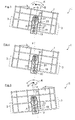
Fig. 3 bis 5 erläutert. So ist in derFig. 3 die Geschirrkorb-Rückseite in einem Zustand gezeigt, in dem der Geschirrkorb 1 aus der Geschirrspülmaschine herausgezogen ist. Das heißt, dass das Anschlussstück 17 von der Zuführleitung 11 entkoppelt ist. Zugleich ist mittels der Höhenverstelleinrichtung 3 der Geschirrkorb 1 in eine Kippstellung I verschwenkt, in der der Geschirrkorb 1 um einen Kippwinkel α aus der Horizontalen zum rechten Bildrand ausgelenkt ist. Entsprechend ist auch das in der Mittelstellung gezeigte Anschlussstück 17 um einen Drehwinkelversatz β aus der Vertikalen ausgelenkt. Der Drehwinkelversatz β ist gemäß derFig. 3 identisch mit dem Kippwinkel α. Das Anschlussstück 17 ist daher in derFig. 3 gegenüber den nicht gezeigten vertikal ausgerichteten Auslassöffnungen 29 der Zuführleitung 11 um den Drehwinkelversatz β verschwenkt. - Damit die Blindstutzen 27 des Anschlussstückes 17 beim nachfolgenden Andockvorgang dichtend in die für die Flüssigkeitsführung nicht benötigten Auslassöffnungen 29 eingreifen kann, muss sich das Anschlussstück 17 um eine Ausgleichsbewegung B verstellen. Diese ist entgegen der Kippbewegung K gerichtet, mit der der Geschirrkorb 1 von der Horizontalstellung in die in der
Fig. 2 gezeigte erste Kippstellung I gestellt wurde. - Bei Durchführung eines Andockvorganges kann der Drehwinkelversatz β mittels der Ausgleichbewegung B des Anschlussstückes 17 ausgeglichen werden, wodurch die Blindstutzen 27 die nicht benötigten Auslassöffnungen 29 der Zuführleitung 11 Flüssigkeitsdicht verschließen können. Die Ausgleichbewegung B wird durch die Zentrierkegel 28 an den Blindstutzen 27 unterstützt, die sich beim Andockvorgang in den korrespondierenden Auslassöffnungen 29 fangen. In der
Fig. 4 ist die Lage des Anschlussstückes 17 bei bereits erfolgtem Andockvorgang gezeigt. Demzufolge befindet sich das Anschlussstück 17, wie auch die nicht dargestellten Auslassöffnungen 29, in vertikaler Ausrichtung. - Bei einem erneuten Herausziehen des in seiner Kippposition I befindlichen Geschirrkorbes 1 wird das Anschlussstück 17 automatisch wieder in seine Mittelstellung zurückgestellt, wie sie in der
Fig. 3 gezeigt ist. - Die automatische Zentrierung des Anschlussstückes 17 in der Mittelstellung ist insbesondere bei einer benutzerseitigen Verstellung von der gezeigten ersten Kippstellung I in die gegenläufige, in der
Fig. 5 gezeigte zweite Kippstellung II von Vorteil. In diesem Fall würde sich nämlich ohne automatische Zentrierung in die Mittelstellung ein sehr großer Drehwinkelversatz zwischen dem Anschlussstück 17 und den Auslassöffnungen 29 der Zuführleitung 11 ergeben. Dies könnte im schlimmsten Fall dazu führen, dass sich die Zentrierkegel 28 der Blindstutzen 27 nicht mehr in den korrespondierenden Auslassöffnungen 29 der Zuführleitung 11 fangen können. - Demgegenüber ist auch in der in der
Fig. 5 gezeigten zweiten Kippstellung II das Anschlussstück 17 mit Hilfe des Materialstegs 31 bereits automatisch in seiner Mittelstellung verstellt. Das Anschlussstück 17 muss daher im darauffolgenden Andockvorgang lediglich einen reduzierten Schwenkweg durchlaufen, und zwar ohne Gefahr, dass sich die Zentrierkegel 35 der Blindstutzen 27 nicht mehr in den korrespondierenden Auslassöffnungen 29 fangen. - In den
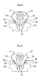
Fig. 6 und 7 sind weitere Ausführungsbeispiele der Stelleinrichtung 31 gezeigt. So ist der in derFig. 6 die als Materialsteg ausgebildete Stelleinrichtung 31 an seinen beiden seitlichen Enden jeweils am Übergang zwischen einem Grundkörper des Anschlussstückes 17 und dem seitlich nach außen ragenden Steckzungen 23 angeformt. Ausgehend davon geht der Materialsteg 31 an beiden Seiten in eine Einschnürung 35 über, an die sich jeweils die seitlichen Bogenabschnitte 33 anschließen. - Diese sind in der
Fig. 6 an ihren oberen Enden miteinander verbunden, während gemäß derFig. 7 jeder der beiden seitlichen Bogenabschnitte 33 oben ein freischwenkbares Ende aufweist. Zwischen der in denFig. 5 und6 nach unten weisenden Flanke der Einschnürung 35 und einem Schulterabschnitt 37 des Grundkörpers des Anschlussstückes 17 ist ein Verstärkungselement 39 angeordnet, das aus einem gummielastischem Material besteht, etwa aus einem am Grundkörper angespritzten Flüssigsilikon. Mit dem so zwischengeordneten Verstärkungselement 39 kann die Federkapazität des Materialstegs 31 erhöht werden. - In der
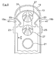
Fig. 8 ist das an der Halteplatte 13 des Zulaufrohrs 7 schwenkbar gelagerte Anschlussstück 17gemäß dem dritten Ausführungsbeispiel gezeigt. Das Anschlussstück 17 ist wie in den vorangegangenen Ausführungsbeispielen in Vertikalrichtung z über ein Bewegungsspiel s lose in der Halteplatte 13 gelagert. Der Materialsteg 31 des Anschlussstücks 17 stützt sich gemäß derFig. 7 mit seinen beiden seitlichen Bogenabschnitten 33 so an den Bewegungsanschlägen 19a, 19b des Randstegs 19 ab, dass das Anschlussstück 17 in der Mittelstellung vorpositioniert ist. - Im Unterschied zu den vorangegangenen Ausführungsbeispielen sind die beiden Bewegungsanschläge 19a, 19b mit Rastausnehmungen 41 versehen, die in die beiden Bogenabschnitte 33 des Materialstegs 31 formschlüssig einragen. Auf diese Weise bleibt die Höhenlage des Anschlussstücks 17, trotz seines Bewegungsspiels s in der Vertikalrichtung z, auch bei herausgezogenem Geschirrkorb 1 unverändert. Das Anschlussstück 17 ist daher für einen erneuten Andockvorgang des Geschirrkorbes 1 bereits lagemäßig mit den Auslassöffnungen 29 ausgerichtet. Die Blindstutzen 27 des Anschlussstücks 17 können daher ohne eine Ausgleichbewegung des Anschlussstückes 17 in Eingriff mit den zugeordneten Auslassöffnungen 29 der Zuführleitung 11 gelangen.
-
- 1
- oberer Geschirrkorb
- 3
- Höhenverstelleinrichtung
- 5
- Sprüharm
- 7
- Zulaufrohr
- 9
- Halteplatte
- 11
- Zuführleitung
- 13
- Halteplatte
- 16
- Querdrahtstrebe
- 17
- Anschlussstück
- 19
- Randsteg
- 21
- Anschlussstutzen
- 23
- Steckzunge
- 25
- Schlitz
- 27
- Blindstutzen
- 29
- Auslassöffnung
- 31
- Stelleinrichtung
- 33
- Bogenabschnitt
- 35
- Einschnürung
- 37
- Anlageschulter
- 39
- Verstärkungselement
- 41
- Rastausnehmungen
- x
- Geräteseitenrichtung
- A
- Schwenkachse
- B
- Ausgleichsbewegung
- K
- Kippbewegung
- I,II
- Kippstellung
- s
- vertikales Bewegungsspiel
Claims (18)
- Geschirrspülmaschine, insbesondere eine Haushalts-Geschirrspülmaschine, mit einem zwischen zumindest zwei Höhenpositionen verstellbaren Geschirrkorb (1), an dem ein zu einer Spülflüssigkeits-Sprüheinrichtung (5) führendes Zulaufrohr (7) befestigt ist, das in Abhängigkeit von der eingestellten Höhenposition an eine erste oder zweite Auslassöffnung (29) einer Zuführleitung (11) ankoppelbar ist, wobei in einer ersten Höhenposition das Zulaufrohr (7) unter Zwischenschaltung eines Anschlussstücks (17) mit der korrespondierenden ersten Auslassöffnung (29) koppelbar ist, während die zweite Auslassöffnung (29) von einem Schließelement (27) des Anschlussstücks (17) verschließbar ist, und bei einer Kippbewegung (K) des Geschirrkorbs (1) von einer Horizontalstellung in eine Kippstellung (I, II) ein Drehwinkelversatz (β) zwischen dem Anschlussstück (17) und den ortsfest angeordneten Auslassöffnungen (29) gebildet ist, so dass das Anschlußstück (17) aus einer Ausgangsstellung in eine von der Ausgangsstellung abweichende Betriebsstellung bringbar, dadurch gekennzeichnet, dass eine Stelleinrichtung (31) vorgesehen ist, die bei entkoppeltem Zulaufrohr (7) das Anschlussstück (17) zumindest teilweise in die Ausgangsstellung zurückführt.
- Geschirrspülmaschine nach Anspruch 1, dadurch gekennzeichnet, dass das Anschlussstück (17) schwenkbar am Zulaufrohr (7) gelagert ist.
- Geschirrspülmaschine nach Anspruch 2, dadurch gekennzeichnet, dass zwei eine Schwenkbewegung des Zulaufrohres (7) begrenzende Bewegungsanschläge (19a, 19b) vorgesehen sind.
- Geschirrspülmaschine nach Anspruch 3, dadurch gekennzeichnet, dass durch die Stelleinrichtung (31) das Anschlußstück (17) bei entkoppeltem Zulaufrohr (7) in eine Mittelstellung zwischen den Bewegungsanschlägen (19a, 19b) verstellbar ist.
- Geschirrspülmaschine nach Anspruch 3 und 4, dadurch gekennzeichnet, dass die Stelleinrichtung (31) zumindest ein Federelement umfasst, mit dem das Anschlussstück (17) in Richtung auf die Mittelstellung elastisch nachgiebig vorgespannt ist.
- Geschirrspülmaschine nach Anspruch 5, dadurch gekennzeichnet, dass das Federelement 'Ω-förmig ausgebildet ist.
- Geschirrspülmaschine nach einem der Ansprüche 1 bis 6, dadurch gekennzeichnet, dass die Stelleinrichtung (31) einstückig im Anschlussstück (17) integriert ist.
- Geschirrspülmaschine nach einem der vorhergehenden Ansprüchen, dadurch gekennzeichnet, dass der Geschirrkorb (1) ausgehend von seiner Horizontalstellung in einer Geräteseitenrichtung (x) in eine erste Kippstellung (I) oder in eine dazu gegenläufige zweite Kippstellung (II) kippbar ist.
- Geschirrspülmaschine nach einem der Ansprüche 4 bis 8, dadurch gekennzeichnet, dass in der Mittelstellung des Anschlussstücks (17) ein Schwenkweg zum ersten und zum zweiten Bewegungsanschlag (19a, 19b) im Wesentlichen gleich groß ist.
- Geschirrspülmaschine nach einem der Ansprüche 3 bis 9, dadurch gekennzeichnet, dass die Bewegungsanschläge (19a, 19b) am Zulaufrohr (7) angeformt sind.
- Geschirrspülmaschine nach einem der Ansprüche 1 bis 10, dadurch gekennzeichnet, dass das Anschlussstück (17) in einer Vertikalrichtung (z) mit Bezug auf das Zulaufrohr (7) mit Bewegungsspiel (s) gelagert ist, und das Anschlussstück (17) zumindest ein Rastelement aufweist, das das Anschlussstück (17) mit Bezug auf das Zulaufrohr (7) in einer vorgegebenen Höhenlage hält.
- Geschirrspülmaschine nach Anspruch 11, dadurch gekennzeichnet, dass das Rastelement ein Bogenabschnitt (33) des Materialstegs (31) ist, der mit einer am zugeordneten Bewegungsanschlag (19a, 19b) ausgebildeten Rastausnehmung (41) in lösbarer Rastverbindung ist.
- Geschirrspülmaschine nach einem der Ansprüche 4 bis 12, dadurch gekennzeichnet, dass das in der Mittelstellung befindliche Anschlussstück (17) in der Horizontalstellung des Geschirrkorbes (1) vertikal ausgerichtet ist.
- Geschirrspülmaschine nach einem der Ansprüche 11 bis 13, dadurch gekennzeichnet, dass das Rastelement in die Stelleinrichtung (31) integriert ist.
- Geschirrspülmaschine nach einem der Ansprüche 1 bis 14, dadurch gekennzeichnet, dass die Geschirrspülmaschine einen Spülbehälter aufweist, wobei der Geschirrkorb (1) durch eine Bewegung entlang einer Achse zwischen einer Position im Spülbehälter und einer Position außerhalb des Spülbehälters verlagerbar ist.
- Geschirrspülmaschine nach Anspruch 15, dadurch gekennzeichnet, dass der Spülbehälter wenigstens eine Öffnung und eine Rückwand aufweist, wobei durch die Öffnung der Geschirrkorb (1) von der Position im Spülbehälter in die Position außerhalb des Spülbehälters bringbar ist, und die Rückwand gegenüber der Öffnung angeordnet ist.
- Geschirrspülmaschine nach Anspruch 15 oder 16, dadurch gekennzeichnet, dass die Kippbewegung (K) eine Drehbewegung um die Achse ist.
- Geschirrspülmaschine nach Anspruch 15, dadurch gekennzeichnet, dass die Zuführleitung (11) an der Rückwand angeordnet ist.
Applications Claiming Priority (1)
| Application Number | Priority Date | Filing Date | Title |
|---|---|---|---|
| DE201010043266 DE102010043266A1 (de) | 2010-11-03 | 2010-11-03 | Geschirrspülmaschine |
Publications (3)
| Publication Number | Publication Date |
|---|---|
| EP2449949A2 true EP2449949A2 (de) | 2012-05-09 |
| EP2449949A3 EP2449949A3 (de) | 2015-01-21 |
| EP2449949B1 EP2449949B1 (de) | 2016-05-18 |
Family
ID=45002603
Family Applications (1)
| Application Number | Title | Priority Date | Filing Date |
|---|---|---|---|
| EP11186153.0A Not-in-force EP2449949B1 (de) | 2010-11-03 | 2011-10-21 | Geschirrspülmaschine |
Country Status (3)
| Country | Link |
|---|---|
| EP (1) | EP2449949B1 (de) |
| DE (1) | DE102010043266A1 (de) |
| RU (1) | RU2566485C2 (de) |
Cited By (5)
| Publication number | Priority date | Publication date | Assignee | Title |
|---|---|---|---|---|
| WO2018202368A1 (en) | 2017-05-03 | 2018-11-08 | Arcelik Anonim Sirketi | A dishwasher comprising a basket |
| CN110856643A (zh) * | 2018-08-24 | 2020-03-03 | 青岛海尔洗碗机有限公司 | 一种喷淋装置及应用该装置的洗碗机 |
| CN110859565A (zh) * | 2018-08-28 | 2020-03-06 | 青岛海尔洗碗机有限公司 | 一种中喷淋洗碗机的引水管固定结构 |
| CN111920357A (zh) * | 2020-09-02 | 2020-11-13 | 珠海格力电器股份有限公司 | 洗碗机 |
| EP4523598A1 (de) * | 2023-09-13 | 2025-03-19 | LG Electronics Inc. | Geschirrspülmaschine |
Families Citing this family (1)
| Publication number | Priority date | Publication date | Assignee | Title |
|---|---|---|---|---|
| CN112716409B (zh) * | 2021-01-07 | 2022-07-15 | 佛山市顺德区美的洗涤电器制造有限公司 | 用于洗碗机的控制方法、处理器、装置、洗碗机以及介质 |
Citations (1)
| Publication number | Priority date | Publication date | Assignee | Title |
|---|---|---|---|---|
| DE102008016485A1 (de) | 2008-03-31 | 2009-10-01 | BSH Bosch und Siemens Hausgeräte GmbH | Geschirrspülmaschine |
Family Cites Families (3)
| Publication number | Priority date | Publication date | Assignee | Title |
|---|---|---|---|---|
| DE4137227C2 (de) * | 1991-11-13 | 1999-12-16 | Aeg Hausgeraete Gmbh | Haushalt-Geschirrspülmaschine mit höhenverstellbarem Oberkorb |
| DE19611054A1 (de) * | 1996-03-20 | 1997-09-25 | Bosch Siemens Hausgeraete | Geschirrspülmaschine |
| IT1301741B1 (it) * | 1998-06-18 | 2000-07-07 | Candy Spa | Macchina lavastoviglie con cestello regolabile in altezza. |
-
2010
- 2010-11-03 DE DE201010043266 patent/DE102010043266A1/de not_active Withdrawn
-
2011
- 2011-10-21 EP EP11186153.0A patent/EP2449949B1/de not_active Not-in-force
- 2011-10-31 RU RU2011143703/12A patent/RU2566485C2/ru active
Patent Citations (1)
| Publication number | Priority date | Publication date | Assignee | Title |
|---|---|---|---|---|
| DE102008016485A1 (de) | 2008-03-31 | 2009-10-01 | BSH Bosch und Siemens Hausgeräte GmbH | Geschirrspülmaschine |
Cited By (7)
| Publication number | Priority date | Publication date | Assignee | Title |
|---|---|---|---|---|
| WO2018202368A1 (en) | 2017-05-03 | 2018-11-08 | Arcelik Anonim Sirketi | A dishwasher comprising a basket |
| CN110856643A (zh) * | 2018-08-24 | 2020-03-03 | 青岛海尔洗碗机有限公司 | 一种喷淋装置及应用该装置的洗碗机 |
| CN110859565A (zh) * | 2018-08-28 | 2020-03-06 | 青岛海尔洗碗机有限公司 | 一种中喷淋洗碗机的引水管固定结构 |
| CN110859565B (zh) * | 2018-08-28 | 2023-02-24 | 青岛海尔洗碗机有限公司 | 一种中喷淋洗碗机的引水管固定结构 |
| CN111920357A (zh) * | 2020-09-02 | 2020-11-13 | 珠海格力电器股份有限公司 | 洗碗机 |
| CN111920357B (zh) * | 2020-09-02 | 2024-02-27 | 珠海格力电器股份有限公司 | 洗碗机 |
| EP4523598A1 (de) * | 2023-09-13 | 2025-03-19 | LG Electronics Inc. | Geschirrspülmaschine |
Also Published As
| Publication number | Publication date |
|---|---|
| EP2449949B1 (de) | 2016-05-18 |
| RU2011143703A (ru) | 2013-05-10 |
| EP2449949A3 (de) | 2015-01-21 |
| DE102010043266A1 (de) | 2012-05-03 |
| RU2566485C2 (ru) | 2015-10-27 |
Similar Documents
| Publication | Publication Date | Title |
|---|---|---|
| EP2449949B1 (de) | Geschirrspülmaschine | |
| EP1935322B1 (de) | Geschirrspülmaschine | |
| EP1136030B1 (de) | Geschirrspüler mit verstellbarem Geschirrkorb | |
| DE4407267C2 (de) | Wassersprühvorrichtung für Geschirrspülmaschine | |
| EP2273910B1 (de) | Geschirrspülmaschine | |
| DE102004022025B3 (de) | Geschirrspülmaschine mit einem höhenverstellbaren Oberkorb | |
| EP3793407B1 (de) | Schiebe-schwenkmechanik einer ablage eines möbels oder haushaltsgerätes und möbel oder haushaltsgerät | |
| DE102012016398B4 (de) | Düseneinrichtung für einen Sprüharm einer Geschirrspülmaschine | |
| EP2187799B1 (de) | Hydraulische kupplung eines höhenverstellbaren geschirrkorbes einer geschirrspülmaschine | |
| WO2014071425A1 (de) | Schubladenausziehführung | |
| EP2441369A2 (de) | Geschirrspülmaschine mit zumindest einer Sprüheinrichtung | |
| WO2018184953A1 (de) | Bodendüse für einen dampfreiniger | |
| EP2106236A1 (de) | Korbführungsschiene für eine geschirrspülmaschine | |
| DE19926962B4 (de) | Geschirrspülmaschine mit höhenverstellbarem Korb | |
| DE2732665C2 (de) | In verschiedenen Höhenlagen in den Spülbehälter einer Geschirrspülmaschine einsetzbarer Geschirrkorb mit einem Sprüharm | |
| EP3169215B1 (de) | Haushaltsgeschirrspülmaschine | |
| EP2875761B1 (de) | Kaffeeautomat | |
| DE4137227C2 (de) | Haushalt-Geschirrspülmaschine mit höhenverstellbarem Oberkorb | |
| EP3047785B1 (de) | Geschirrspülmaschine, insbesondere haushaltsgeschirrspülmaschine | |
| DE2919140A1 (de) | Spuelmaschine | |
| DE10056314A1 (de) | Befestigungsvorrichtung für Scheinwerferreinigungsanlage | |
| EP3025624B1 (de) | Kaffeeautomat | |
| DE102013211554B4 (de) | Auszugssystem für eine Geschirrspülmaschine | |
| DE3315999A1 (de) | Auszieheinrichtung fuer einen schrank, vorzugsweise einen vorratsschrank | |
| WO2008061883A1 (de) | Geschirrspülmaschine mit höhenanpassbarem anschlussrohr |
Legal Events
| Date | Code | Title | Description |
|---|---|---|---|
| PUAI | Public reference made under article 153(3) epc to a published international application that has entered the european phase |
Free format text: ORIGINAL CODE: 0009012 |
|
| AK | Designated contracting states |
Kind code of ref document: A2 Designated state(s): AL AT BE BG CH CY CZ DE DK EE ES FI FR GB GR HR HU IE IS IT LI LT LU LV MC MK MT NL NO PL PT RO RS SE SI SK SM TR |
|
| AX | Request for extension of the european patent |
Extension state: BA ME |
|
| PUAL | Search report despatched |
Free format text: ORIGINAL CODE: 0009013 |
|
| AK | Designated contracting states |
Kind code of ref document: A3 Designated state(s): AL AT BE BG CH CY CZ DE DK EE ES FI FR GB GR HR HU IE IS IT LI LT LU LV MC MK MT NL NO PL PT RO RS SE SI SK SM TR |
|
| AX | Request for extension of the european patent |
Extension state: BA ME |
|
| RIC1 | Information provided on ipc code assigned before grant |
Ipc: A47L 15/50 20060101AFI20141218BHEP |
|
| RAP1 | Party data changed (applicant data changed or rights of an application transferred) |
Owner name: BSH HAUSGERAETE GMBH |
|
| 17P | Request for examination filed |
Effective date: 20150721 |
|
| RBV | Designated contracting states (corrected) |
Designated state(s): AL AT BE BG CH CY CZ DE DK EE ES FI FR GB GR HR HU IE IS IT LI LT LU LV MC MK MT NL NO PL PT RO RS SE SI SK SM TR |
|
| GRAP | Despatch of communication of intention to grant a patent |
Free format text: ORIGINAL CODE: EPIDOSNIGR1 |
|
| INTG | Intention to grant announced |
Effective date: 20160114 |
|
| GRAS | Grant fee paid |
Free format text: ORIGINAL CODE: EPIDOSNIGR3 |
|
| GRAA | (expected) grant |
Free format text: ORIGINAL CODE: 0009210 |
|
| AK | Designated contracting states |
Kind code of ref document: B1 Designated state(s): AL AT BE BG CH CY CZ DE DK EE ES FI FR GB GR HR HU IE IS IT LI LT LU LV MC MK MT NL NO PL PT RO RS SE SI SK SM TR |
|
| REG | Reference to a national code |
Ref country code: GB Ref legal event code: FG4D Free format text: NOT ENGLISH |
|
| REG | Reference to a national code |
Ref country code: CH Ref legal event code: EP |
|
| REG | Reference to a national code |
Ref country code: IE Ref legal event code: FG4D Free format text: LANGUAGE OF EP DOCUMENT: GERMAN Ref country code: AT Ref legal event code: REF Ref document number: 799664 Country of ref document: AT Kind code of ref document: T Effective date: 20160615 |
|
| REG | Reference to a national code |
Ref country code: DE Ref legal event code: R096 Ref document number: 502011009781 Country of ref document: DE |
|
| REG | Reference to a national code |
Ref country code: NL Ref legal event code: MP Effective date: 20160518 |
|
| REG | Reference to a national code |
Ref country code: LT Ref legal event code: MG4D |
|
| PG25 | Lapsed in a contracting state [announced via postgrant information from national office to epo] |
Ref country code: FI Free format text: LAPSE BECAUSE OF FAILURE TO SUBMIT A TRANSLATION OF THE DESCRIPTION OR TO PAY THE FEE WITHIN THE PRESCRIBED TIME-LIMIT Effective date: 20160518 Ref country code: LT Free format text: LAPSE BECAUSE OF FAILURE TO SUBMIT A TRANSLATION OF THE DESCRIPTION OR TO PAY THE FEE WITHIN THE PRESCRIBED TIME-LIMIT Effective date: 20160518 Ref country code: NL Free format text: LAPSE BECAUSE OF FAILURE TO SUBMIT A TRANSLATION OF THE DESCRIPTION OR TO PAY THE FEE WITHIN THE PRESCRIBED TIME-LIMIT Effective date: 20160518 Ref country code: NO Free format text: LAPSE BECAUSE OF FAILURE TO SUBMIT A TRANSLATION OF THE DESCRIPTION OR TO PAY THE FEE WITHIN THE PRESCRIBED TIME-LIMIT Effective date: 20160818 |
|
| PG25 | Lapsed in a contracting state [announced via postgrant information from national office to epo] |
Ref country code: RS Free format text: LAPSE BECAUSE OF FAILURE TO SUBMIT A TRANSLATION OF THE DESCRIPTION OR TO PAY THE FEE WITHIN THE PRESCRIBED TIME-LIMIT Effective date: 20160518 Ref country code: LV Free format text: LAPSE BECAUSE OF FAILURE TO SUBMIT A TRANSLATION OF THE DESCRIPTION OR TO PAY THE FEE WITHIN THE PRESCRIBED TIME-LIMIT Effective date: 20160518 Ref country code: HR Free format text: LAPSE BECAUSE OF FAILURE TO SUBMIT A TRANSLATION OF THE DESCRIPTION OR TO PAY THE FEE WITHIN THE PRESCRIBED TIME-LIMIT Effective date: 20160518 Ref country code: SE Free format text: LAPSE BECAUSE OF FAILURE TO SUBMIT A TRANSLATION OF THE DESCRIPTION OR TO PAY THE FEE WITHIN THE PRESCRIBED TIME-LIMIT Effective date: 20160518 Ref country code: GR Free format text: LAPSE BECAUSE OF FAILURE TO SUBMIT A TRANSLATION OF THE DESCRIPTION OR TO PAY THE FEE WITHIN THE PRESCRIBED TIME-LIMIT Effective date: 20160819 Ref country code: PT Free format text: LAPSE BECAUSE OF FAILURE TO SUBMIT A TRANSLATION OF THE DESCRIPTION OR TO PAY THE FEE WITHIN THE PRESCRIBED TIME-LIMIT Effective date: 20160919 Ref country code: ES Free format text: LAPSE BECAUSE OF FAILURE TO SUBMIT A TRANSLATION OF THE DESCRIPTION OR TO PAY THE FEE WITHIN THE PRESCRIBED TIME-LIMIT Effective date: 20160518 |
|
| PG25 | Lapsed in a contracting state [announced via postgrant information from national office to epo] |
Ref country code: IT Free format text: LAPSE BECAUSE OF FAILURE TO SUBMIT A TRANSLATION OF THE DESCRIPTION OR TO PAY THE FEE WITHIN THE PRESCRIBED TIME-LIMIT Effective date: 20160518 |
|
| PG25 | Lapsed in a contracting state [announced via postgrant information from national office to epo] |
Ref country code: CZ Free format text: LAPSE BECAUSE OF FAILURE TO SUBMIT A TRANSLATION OF THE DESCRIPTION OR TO PAY THE FEE WITHIN THE PRESCRIBED TIME-LIMIT Effective date: 20160518 Ref country code: RO Free format text: LAPSE BECAUSE OF FAILURE TO SUBMIT A TRANSLATION OF THE DESCRIPTION OR TO PAY THE FEE WITHIN THE PRESCRIBED TIME-LIMIT Effective date: 20160518 Ref country code: DK Free format text: LAPSE BECAUSE OF FAILURE TO SUBMIT A TRANSLATION OF THE DESCRIPTION OR TO PAY THE FEE WITHIN THE PRESCRIBED TIME-LIMIT Effective date: 20160518 Ref country code: SK Free format text: LAPSE BECAUSE OF FAILURE TO SUBMIT A TRANSLATION OF THE DESCRIPTION OR TO PAY THE FEE WITHIN THE PRESCRIBED TIME-LIMIT Effective date: 20160518 Ref country code: EE Free format text: LAPSE BECAUSE OF FAILURE TO SUBMIT A TRANSLATION OF THE DESCRIPTION OR TO PAY THE FEE WITHIN THE PRESCRIBED TIME-LIMIT Effective date: 20160518 |
|
| REG | Reference to a national code |
Ref country code: DE Ref legal event code: R097 Ref document number: 502011009781 Country of ref document: DE |
|
| PG25 | Lapsed in a contracting state [announced via postgrant information from national office to epo] |
Ref country code: SM Free format text: LAPSE BECAUSE OF FAILURE TO SUBMIT A TRANSLATION OF THE DESCRIPTION OR TO PAY THE FEE WITHIN THE PRESCRIBED TIME-LIMIT Effective date: 20160518 Ref country code: PL Free format text: LAPSE BECAUSE OF FAILURE TO SUBMIT A TRANSLATION OF THE DESCRIPTION OR TO PAY THE FEE WITHIN THE PRESCRIBED TIME-LIMIT Effective date: 20160518 Ref country code: BE Free format text: LAPSE BECAUSE OF NON-PAYMENT OF DUE FEES Effective date: 20161031 |
|
| PLBE | No opposition filed within time limit |
Free format text: ORIGINAL CODE: 0009261 |
|
| STAA | Information on the status of an ep patent application or granted ep patent |
Free format text: STATUS: NO OPPOSITION FILED WITHIN TIME LIMIT |
|
| 26N | No opposition filed |
Effective date: 20170221 |
|
| PG25 | Lapsed in a contracting state [announced via postgrant information from national office to epo] |
Ref country code: SI Free format text: LAPSE BECAUSE OF FAILURE TO SUBMIT A TRANSLATION OF THE DESCRIPTION OR TO PAY THE FEE WITHIN THE PRESCRIBED TIME-LIMIT Effective date: 20160518 |
|
| REG | Reference to a national code |
Ref country code: CH Ref legal event code: PL |
|
| GBPC | Gb: european patent ceased through non-payment of renewal fee |
Effective date: 20161021 |
|
| PG25 | Lapsed in a contracting state [announced via postgrant information from national office to epo] |
Ref country code: MC Free format text: LAPSE BECAUSE OF FAILURE TO SUBMIT A TRANSLATION OF THE DESCRIPTION OR TO PAY THE FEE WITHIN THE PRESCRIBED TIME-LIMIT Effective date: 20160518 |
|
| REG | Reference to a national code |
Ref country code: IE Ref legal event code: MM4A |
|
| REG | Reference to a national code |
Ref country code: FR Ref legal event code: ST Effective date: 20170630 |
|
| PG25 | Lapsed in a contracting state [announced via postgrant information from national office to epo] |
Ref country code: GB Free format text: LAPSE BECAUSE OF NON-PAYMENT OF DUE FEES Effective date: 20161021 Ref country code: CH Free format text: LAPSE BECAUSE OF NON-PAYMENT OF DUE FEES Effective date: 20161031 Ref country code: FR Free format text: LAPSE BECAUSE OF NON-PAYMENT OF DUE FEES Effective date: 20161102 Ref country code: LI Free format text: LAPSE BECAUSE OF NON-PAYMENT OF DUE FEES Effective date: 20161031 |
|
| PG25 | Lapsed in a contracting state [announced via postgrant information from national office to epo] |
Ref country code: LU Free format text: LAPSE BECAUSE OF NON-PAYMENT OF DUE FEES Effective date: 20161021 |
|
| PG25 | Lapsed in a contracting state [announced via postgrant information from national office to epo] |
Ref country code: IE Free format text: LAPSE BECAUSE OF NON-PAYMENT OF DUE FEES Effective date: 20161021 |
|
| REG | Reference to a national code |
Ref country code: BE Ref legal event code: MM Effective date: 20161031 |
|
| REG | Reference to a national code |
Ref country code: AT Ref legal event code: MM01 Ref document number: 799664 Country of ref document: AT Kind code of ref document: T Effective date: 20161021 |
|
| PG25 | Lapsed in a contracting state [announced via postgrant information from national office to epo] |
Ref country code: AT Free format text: LAPSE BECAUSE OF NON-PAYMENT OF DUE FEES Effective date: 20161021 |
|
| PG25 | Lapsed in a contracting state [announced via postgrant information from national office to epo] |
Ref country code: CY Free format text: LAPSE BECAUSE OF FAILURE TO SUBMIT A TRANSLATION OF THE DESCRIPTION OR TO PAY THE FEE WITHIN THE PRESCRIBED TIME-LIMIT Effective date: 20160518 Ref country code: HU Free format text: LAPSE BECAUSE OF FAILURE TO SUBMIT A TRANSLATION OF THE DESCRIPTION OR TO PAY THE FEE WITHIN THE PRESCRIBED TIME-LIMIT; INVALID AB INITIO Effective date: 20111021 |
|
| PG25 | Lapsed in a contracting state [announced via postgrant information from national office to epo] |
Ref country code: IS Free format text: LAPSE BECAUSE OF FAILURE TO SUBMIT A TRANSLATION OF THE DESCRIPTION OR TO PAY THE FEE WITHIN THE PRESCRIBED TIME-LIMIT Effective date: 20160518 Ref country code: MT Free format text: LAPSE BECAUSE OF FAILURE TO SUBMIT A TRANSLATION OF THE DESCRIPTION OR TO PAY THE FEE WITHIN THE PRESCRIBED TIME-LIMIT Effective date: 20160518 Ref country code: MK Free format text: LAPSE BECAUSE OF FAILURE TO SUBMIT A TRANSLATION OF THE DESCRIPTION OR TO PAY THE FEE WITHIN THE PRESCRIBED TIME-LIMIT Effective date: 20160518 Ref country code: TR Free format text: LAPSE BECAUSE OF FAILURE TO SUBMIT A TRANSLATION OF THE DESCRIPTION OR TO PAY THE FEE WITHIN THE PRESCRIBED TIME-LIMIT Effective date: 20160518 |
|
| PG25 | Lapsed in a contracting state [announced via postgrant information from national office to epo] |
Ref country code: BG Free format text: LAPSE BECAUSE OF FAILURE TO SUBMIT A TRANSLATION OF THE DESCRIPTION OR TO PAY THE FEE WITHIN THE PRESCRIBED TIME-LIMIT Effective date: 20160518 |
|
| PG25 | Lapsed in a contracting state [announced via postgrant information from national office to epo] |
Ref country code: AL Free format text: LAPSE BECAUSE OF FAILURE TO SUBMIT A TRANSLATION OF THE DESCRIPTION OR TO PAY THE FEE WITHIN THE PRESCRIBED TIME-LIMIT Effective date: 20160518 |
|
| PGFP | Annual fee paid to national office [announced via postgrant information from national office to epo] |
Ref country code: DE Payment date: 20211031 Year of fee payment: 11 |
|
| REG | Reference to a national code |
Ref country code: DE Ref legal event code: R119 Ref document number: 502011009781 Country of ref document: DE |
|
| PG25 | Lapsed in a contracting state [announced via postgrant information from national office to epo] |
Ref country code: DE Free format text: LAPSE BECAUSE OF NON-PAYMENT OF DUE FEES Effective date: 20230503 |