EP2449636B1 - Connector for flat conductive strips, particularly flexible luminous strips having light-emitting diodes - Google Patents
Connector for flat conductive strips, particularly flexible luminous strips having light-emitting diodes Download PDFInfo
- Publication number
- EP2449636B1 EP2449636B1 EP10742267.7A EP10742267A EP2449636B1 EP 2449636 B1 EP2449636 B1 EP 2449636B1 EP 10742267 A EP10742267 A EP 10742267A EP 2449636 B1 EP2449636 B1 EP 2449636B1
- Authority
- EP
- European Patent Office
- Prior art keywords
- strip
- connector
- ribbon
- connector according
- cover
- Prior art date
- Legal status (The legal status is an assumption and is not a legal conclusion. Google has not performed a legal analysis and makes no representation as to the accuracy of the status listed.)
- Not-in-force
Links
Images


Classifications
-
- H—ELECTRICITY
- H01—ELECTRIC ELEMENTS
- H01R—ELECTRICALLY-CONDUCTIVE CONNECTIONS; STRUCTURAL ASSOCIATIONS OF A PLURALITY OF MUTUALLY-INSULATED ELECTRICAL CONNECTING ELEMENTS; COUPLING DEVICES; CURRENT COLLECTORS
- H01R13/00—Details of coupling devices of the kinds covered by groups H01R12/70 or H01R24/00 - H01R33/00
- H01R13/66—Structural association with built-in electrical component
- H01R13/717—Structural association with built-in electrical component with built-in light source
- H01R13/7175—Light emitting diodes (LEDs)
-
- F—MECHANICAL ENGINEERING; LIGHTING; HEATING; WEAPONS; BLASTING
- F21—LIGHTING
- F21S—NON-PORTABLE LIGHTING DEVICES; SYSTEMS THEREOF; VEHICLE LIGHTING DEVICES SPECIALLY ADAPTED FOR VEHICLE EXTERIORS
- F21S4/00—Lighting devices or systems using a string or strip of light sources
- F21S4/20—Lighting devices or systems using a string or strip of light sources with light sources held by or within elongate supports
- F21S4/22—Lighting devices or systems using a string or strip of light sources with light sources held by or within elongate supports flexible or deformable, e.g. into a curved shape
-
- H—ELECTRICITY
- H01—ELECTRIC ELEMENTS
- H01R—ELECTRICALLY-CONDUCTIVE CONNECTIONS; STRUCTURAL ASSOCIATIONS OF A PLURALITY OF MUTUALLY-INSULATED ELECTRICAL CONNECTING ELEMENTS; COUPLING DEVICES; CURRENT COLLECTORS
- H01R12/00—Structural associations of a plurality of mutually-insulated electrical connecting elements, specially adapted for printed circuits, e.g. printed circuit boards [PCB], flat or ribbon cables, or like generally planar structures, e.g. terminal strips, terminal blocks; Coupling devices specially adapted for printed circuits, flat or ribbon cables, or like generally planar structures; Terminals specially adapted for contact with, or insertion into, printed circuits, flat or ribbon cables, or like generally planar structures
- H01R12/70—Coupling devices
- H01R12/77—Coupling devices for flexible printed circuits, flat or ribbon cables or like structures
- H01R12/78—Coupling devices for flexible printed circuits, flat or ribbon cables or like structures connecting to other flexible printed circuits, flat or ribbon cables or like structures
-
- F—MECHANICAL ENGINEERING; LIGHTING; HEATING; WEAPONS; BLASTING
- F21—LIGHTING
- F21S—NON-PORTABLE LIGHTING DEVICES; SYSTEMS THEREOF; VEHICLE LIGHTING DEVICES SPECIALLY ADAPTED FOR VEHICLE EXTERIORS
- F21S2/00—Systems of lighting devices, not provided for in main groups F21S4/00 - F21S10/00 or F21S19/00, e.g. of modular construction
-
- F—MECHANICAL ENGINEERING; LIGHTING; HEATING; WEAPONS; BLASTING
- F21—LIGHTING
- F21V—FUNCTIONAL FEATURES OR DETAILS OF LIGHTING DEVICES OR SYSTEMS THEREOF; STRUCTURAL COMBINATIONS OF LIGHTING DEVICES WITH OTHER ARTICLES, NOT OTHERWISE PROVIDED FOR
- F21V23/00—Arrangement of electric circuit elements in or on lighting devices
- F21V23/06—Arrangement of electric circuit elements in or on lighting devices the elements being coupling devices, e.g. connectors
-
- F—MECHANICAL ENGINEERING; LIGHTING; HEATING; WEAPONS; BLASTING
- F21—LIGHTING
- F21Y—INDEXING SCHEME ASSOCIATED WITH SUBCLASSES F21K, F21L, F21S and F21V, RELATING TO THE FORM OR THE KIND OF THE LIGHT SOURCES OR OF THE COLOUR OF THE LIGHT EMITTED
- F21Y2115/00—Light-generating elements of semiconductor light sources
- F21Y2115/10—Light-emitting diodes [LED]
-
- H—ELECTRICITY
- H01—ELECTRIC ELEMENTS
- H01R—ELECTRICALLY-CONDUCTIVE CONNECTIONS; STRUCTURAL ASSOCIATIONS OF A PLURALITY OF MUTUALLY-INSULATED ELECTRICAL CONNECTING ELEMENTS; COUPLING DEVICES; CURRENT COLLECTORS
- H01R13/00—Details of coupling devices of the kinds covered by groups H01R12/70 or H01R24/00 - H01R33/00
- H01R13/46—Bases; Cases
- H01R13/465—Identification means, e.g. labels, tags, markings
-
- H—ELECTRICITY
- H01—ELECTRIC ELEMENTS
- H01R—ELECTRICALLY-CONDUCTIVE CONNECTIONS; STRUCTURAL ASSOCIATIONS OF A PLURALITY OF MUTUALLY-INSULATED ELECTRICAL CONNECTING ELEMENTS; COUPLING DEVICES; CURRENT COLLECTORS
- H01R13/00—Details of coupling devices of the kinds covered by groups H01R12/70 or H01R24/00 - H01R33/00
- H01R13/46—Bases; Cases
- H01R13/50—Bases; Cases formed as an integral body
- H01R13/501—Bases; Cases formed as an integral body comprising an integral hinge or a frangible part
-
- H—ELECTRICITY
- H01—ELECTRIC ELEMENTS
- H01R—ELECTRICALLY-CONDUCTIVE CONNECTIONS; STRUCTURAL ASSOCIATIONS OF A PLURALITY OF MUTUALLY-INSULATED ELECTRICAL CONNECTING ELEMENTS; COUPLING DEVICES; CURRENT COLLECTORS
- H01R13/00—Details of coupling devices of the kinds covered by groups H01R12/70 or H01R24/00 - H01R33/00
- H01R13/58—Means for relieving strain on wire connection, e.g. cord grip, for avoiding loosening of connections between wires and terminals within a coupling device terminating a cable
- H01R13/5833—Means for relieving strain on wire connection, e.g. cord grip, for avoiding loosening of connections between wires and terminals within a coupling device terminating a cable the cable being forced in a tortuous or curved path, e.g. knots in cable
-
- H—ELECTRICITY
- H01—ELECTRIC ELEMENTS
- H01R—ELECTRICALLY-CONDUCTIVE CONNECTIONS; STRUCTURAL ASSOCIATIONS OF A PLURALITY OF MUTUALLY-INSULATED ELECTRICAL CONNECTING ELEMENTS; COUPLING DEVICES; CURRENT COLLECTORS
- H01R4/00—Electrically-conductive connections between two or more conductive members in direct contact, i.e. touching one another; Means for effecting or maintaining such contact; Electrically-conductive connections having two or more spaced connecting locations for conductors and using contact members penetrating insulation
- H01R4/28—Clamped connections, spring connections
- H01R4/50—Clamped connections, spring connections utilising a cam, wedge, cone or ball also combined with a screw
- H01R4/5066—Clamped connections, spring connections utilising a cam, wedge, cone or ball also combined with a screw mounted in an insulating housing having a cover providing clamping force
Definitions
- the present invention relates to a flat conductor ribbon connector, including flexible light ribbons.
- Light ribbons comprising light-emitting diodes distributed over their length are already known, for example by US5337225 or US2005180162 .
- the ribbon comprises round-section conductor wires embedded in a support made of polymeric material, in which the diodes are also encased.
- the light ribbons covered by the invention differ from the ribbons of the above-mentioned document in that they consist of a flexible printed circuit supporting electroluminescent diodes, usually called LEDs, with high brightness.
- the ribbon comprises an insulating support of flexible plastic material on which electrically conductive parallel tracks are formed.
- the tracks are generally coated in the plastic material which ensures their electrical insulation, but they appear locally naked in areas spaced evenly along the ribbon to allow the electrical connection of the LEDs on these tracks, or to allow the electrical connection two ribbons between them.
- the ribbon may comprise two conductive tracks for single two-way tapes, or several tracks, for example four, for multi-path systems.
- Such light ribbons one side of which may be self-adhesive for ease of application, may be used for markup, accent lighting, decoration, etc.
- these ribbons are relatively little used for reasons of complexity installation. A major difficulty comes from the fact that these ribbons are usually connected by welding, which makes their use difficult.
- Connectors have already been proposed to allow easier connection of end-to-end conductive ribbons.
- Such connectors generally use electrical connection strips comprising pointed pins which punch the conductive wires, or V-shaped pins which fit on the electrically conductive wires transversely, the pressure movement which must be exerted on the said bars causing the piercing of the insulation of the conducting wire.
- These latter systems are known essentially for flexible plies of several wire conductors of round section, as described in FR2257158 , US4027941 , or US4415215 for example.
- the implementation of the connector requires that the two conductor elements to be connected are simultaneously present in the connector before making the connection, because said pin bars are simultaneously inserted on the ends of the conductive elements. Thus, it is generally not possible to put the connector on the end of a single ribbon, and only later connect the second ribbon on this connector.
- the document DE10065972 describes a device according to the preamble of claim 1.
- US7309249 describes a similar system for connecting ribbons with flat conductive tracks.
- the V-pins of this system fit on the conductive tracks by bending them longitudinally.
- This system is only suitable if the ribbon is always placed in the same direction in the connector, namely with the non-electrically insulated side of the side of said pins. If the ribbon is placed in an inverted direction, the pin will be in contact with the insulating layer, formed by the insulating polymer support, carrying the conductive track, and the electrical contact will not be made or will be only random.
- the present invention aims to solve the problems mentioned above, and aims in particular to allow easy connection of light ribbons, seamless or complex handling. It also aims to provide a reliable electrical connection, allowing the electrical connection regardless of the direction of installation of the ribbon in the connector. It thus aims to allow an easy connection of butt tape in a straight line, or to provide a connection of tapes placed at right angles, or with any angle formed between them, by using an element of intermediate ribbon forming the angle and connected to each of said straight ribbons to connect.
- the subject of the invention is a connector according to claim 1.
- connection of the ribbon on the connector is done by inserting the end of the ribbon into the connector, in the longitudinal direction of the ribbon, until the ends of the conductive tracks s' insert electrical connection elements into the slots.
- the electrical connection then being automatically achieved by the pinching of the connection elements on the end of the ribbon at the level of the conductive tracks.
- the electrical connection elements are platelets of conductive metal which extend in a longitudinal plane and perpendicular to said general plane, and which comprise at each end two tabs which define between them said slot. It should be noted that this arrangement makes it possible to ensure the electrical contact whatever the orientation of the ribbon in the connector, despite the presence of the insulating support ribbon, since the ends of the conductive tracks are necessarily in contact with one of the tabs or with the other.
- the pads are kept inserted or overmolded in a housing body and the tabs protrude on each side in an insertion housing adapted to receive the end of the ribbon.
- a housing body adapted to receive the end of the ribbon.
- slides are provided in each housing to guide the ribbon edges when it is inserted into the connector.
- the latter comprises locking means, provided for pinching and jamming the ribbon, beyond the end zones where the electrical connection is made.
- the locking means comprise baffles transverse to the longitudinal direction, which apply to the ribbon and cause it to undergo a succession of alternating bending deformations capable of blocking it.
- the baffles are formed by ribs and grooves formed respectively on the body of the housing and on a connector cover at the ribbon insertion housing.
- the cover is preferably hinged to the body by a side hinge, and locking means are provided to lock the cover on the body of the housing.
- the lid comprises a complementary rib which presses on the tabs of the plates when the lid is closed, to exert an additional pinching force of the ends of the conductive tracks between said tabs.
- the invention also relates to a system of flat light ribbons carrying electroluminescent diodes, composed of a plurality of elements ribbons connected end to end by connectors as defined above.
- the ribbon elements may be connected in alignment with each other, or at any angle, to adapt the arrangement of the ribbon system to the configuration of the medium and the environment where it is desired to place said ribbons.
- connecting elements may in particular provide specific connecting elements to form these angles, comprising a single ribbon, carrying only the conductive tracks excluding LEDs, folded on itself at any angle, and having at each end a connector according to the invention.
- the corner elements can be prepared, and during installation, simply cut the rectilinear elements of light ribbons to the desired length, at the connection pads provided on these ribbons, and insert the ends thus cut into the connectors mounted on the corner elements.
- polarization markings are preferably provided on the housings.
- the ribbon elements 1 are arranged in line and connected by a single flat ribbon 15, without LEDs, connected to the ends ribbon elements 1 by connectors 2 according to the invention.
- the ribbon elements 1 are arranged at right angles and connected by a single flat ribbon 15 ', without LEDs, folded back on itself at the desired angle, here at 90 °.
- this connector consists of a double housing 20 having a body 21 extending in a general plane P1 which corresponds to the plane of the light ribbons to be connected, that is to say according to the plane of the sheet of the figure 3 , and in the longitudinal direction XX of said ribbons.
- the housing comprises two covers 22, 23 one beside the other, pivotally articulated on the body by lateral hinges 29 extending along a hinge line L oriented in the longitudinal direction XX, the two lids being symmetrical with respect to a median plane P2 perpendicular to said longitudinal direction XX.
- the covers 22, 23 are clipped in the closed position on the body by engagement of a cutout 24 of the cover on a lug 25 of the body.
- the covers 22, 23 close housing 26 made in each part of the body and intended to receive the ends of the ribbons to be connected, the housing width corresponding to that of the ribbons.
- slides 27 are formed on the side walls of the housing 26 to guide the end of the ribbon during its insertion into the connector, as will be seen later.
- each wafer 3 corresponds to a track 10 'of the ribbon.
- the connectors for ribbons with a number of tracks other than two or four.
- the connectors carry on their cover and on the body, in the housing 26, polarization markings + and - to facilitate connections avoiding polarity errors.
- polarization markings + and - to facilitate connections avoiding polarity errors.
- the connector system according to the invention makes it possible to simply manage these inversions because the ends of the ribbons can be placed in the connectors without worrying about the orientation of the ribbon: the figure 2 shows that on one side of the corner, connected on the ribbon 1, the insulating layer 13 of the single ribbon 15 'is located on the top, and on the other side it is the support 12 of the ribbon 15' which is apparent, the conductive tracks being then on this side , below the support 12.
- the connection of the connector remains possible, because the electrical contact between the pads 14 and the pads 3 will then be via the tab 31 of the pads located towards the body of the housing 20 instead of being via the tab located towards the lid, as previously described.
- the connector 2a is then connected to the ribbon 15 'in the opposite direction of the connector 2.
- the said + and - marks make it possible to ensure, in relation to the corresponding tracks of the ribbon, that the polarities are well respected when the connector 2 is connected. both on the ribbon side of the single flat ribbon 15 'and on the ribbon side 1'.
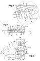
- the tracks and their positions in the connectors may be identified by RGB-like markers - for example, as illustrated figure 8 , or equivalent locations.
- the invention is not limited to the embodiment of the connector described above solely by way of example.
- the pivoting cover could be replaced by any other cover system snap on the body and to ensure the locking tape by baffle systems or equivalent locking systems.
Landscapes
- Engineering & Computer Science (AREA)
- Physics & Mathematics (AREA)
- Microelectronics & Electronic Packaging (AREA)
- Optics & Photonics (AREA)
- General Engineering & Computer Science (AREA)
- Coupling Device And Connection With Printed Circuit (AREA)
- Multi-Conductor Connections (AREA)
- Led Device Packages (AREA)
- Connector Housings Or Holding Contact Members (AREA)
- Details Of Connecting Devices For Male And Female Coupling (AREA)
Description
La présente invention concerne un connecteur de rubans conducteurs plats, notamment de rubans lumineux flexibles.The present invention relates to a flat conductor ribbon connector, including flexible light ribbons.
Des rubans lumineux comportant des diodes électroluminescentes réparties sur leur longueur sont déjà connus, par exemple par
Typiquement, les rubans lumineux visés par l'invention diffèrent des rubans du document précité en ce qu'ils sont constitués d'un circuit imprimé souple supportant des diodes électroluminescentes, classiquement appelées LED, à haute luminosité. Le ruban comporte un support isolant en matière plastique souple sur lequel des pistes parallèles électriquement conductrices sont formées. Les pistes sont globalement enrobées dans la matière plastique qui assure leur isolation électrique, mais elles apparaissent localement à nu dans des zones situées à espacement régulier le long du ruban pour y permettre le raccordement électrique des LEDs sur ces pistes, ou pour permettre le raccordement électrique de deux éléments de rubans entre eux. Le ruban peut comporter deux pistes conductrices pour des rubans simples à deux voies, ou plusieurs pistes, par exemple quatre, pour des systèmes multi-voies.Typically, the light ribbons covered by the invention differ from the ribbons of the above-mentioned document in that they consist of a flexible printed circuit supporting electroluminescent diodes, usually called LEDs, with high brightness. The ribbon comprises an insulating support of flexible plastic material on which electrically conductive parallel tracks are formed. The tracks are generally coated in the plastic material which ensures their electrical insulation, but they appear locally naked in areas spaced evenly along the ribbon to allow the electrical connection of the LEDs on these tracks, or to allow the electrical connection two ribbons between them. The ribbon may comprise two conductive tracks for single two-way tapes, or several tracks, for example four, for multi-path systems.
De tels rubans lumineux, dont une face peut être autocollante pour faciliter leur application, peuvent être utilisés pour du balisage, de l'éclairage d'appoint, de la décoration, etc. Actuellement, ces rubans sont relativement peu utilisés pour des raisons de complexité d'installation. Une difficulté principale provient du fait que ces rubans sont habituellement connectés par soudure, ce qui rend leur utilisation difficile.Such light ribbons, one side of which may be self-adhesive for ease of application, may be used for markup, accent lighting, decoration, etc. Currently, these ribbons are relatively little used for reasons of complexity installation. A major difficulty comes from the fact that these ribbons are usually connected by welding, which makes their use difficult.
Il a déjà été proposé des connecteurs visant à permettre une connexion plus facile de rubans conducteurs bout à bout. De tels connecteurs utilisent généralement des barrettes de connexion électriques comportant des picots en pointe qui poinçonnent les fils conducteurs, ou des picots en V qui s'insèrent sur les fils conducteurs électriques transversalement, le mouvement de pression qui doit être exercé sur les dites barrettes provoquant le percement de l'isolant du fil conducteur. Ces derniers systèmes sont connus essentiellement pour des nappes souples de plusieurs conducteurs filaires de section ronde, comme décrits dans
Le document
Un autre inconvénient courant des systèmes assurant la connexion électrique par un picot ou cavalier en V s'insérant transversalement sur le conducteur électrique, est que la mise en place des rubans dans le connecteur et la connexion électrique proprement dite sont des opérations séparées qu'il faut exécuter successivement. De plus, ces connecteurs ne sont généralement pas démontables, ou au moins il y a un risque important que le conducteur reste marqué au niveau où le picot en V a été pressé sur le conducteur.Another common disadvantage of the systems providing the electrical connection by a pin or jumper V inserted transversely on the electrical conductor, is that the introduction of the ribbons in the connector and the actual electrical connection are separate operations that he must be performed successively. In addition, these connectors are generally not removable, or at least there is a significant risk that the driver remains marked at the point where the V-shaped pin was pressed on the driver.
La présente invention a pour but de résoudre les problèmes évoqués ci-dessus, et vise en particulier à permettre une connexion aisée des rubans lumineux, sans soudure ni manipulation complexe. Elle vise aussi à assurer une liaison électrique fiable, permettant la connexion électrique quel que soit le sens de mise en place du ruban dans le connecteur. Elle vise ainsi à permettre une connexion aisée de ruban bout à bout en ligne droite, ou à assurer une connexion de rubans placés à angle droit, ou avec n'importe quel angle formé entre eux, en utilisant un élément de ruban intermédiaire formant l'angle et connecté sur chacun des dits rubans rectilignes à connecter.The present invention aims to solve the problems mentioned above, and aims in particular to allow easy connection of light ribbons, seamless or complex handling. It also aims to provide a reliable electrical connection, allowing the electrical connection regardless of the direction of installation of the ribbon in the connector. It thus aims to allow an easy connection of butt tape in a straight line, or to provide a connection of tapes placed at right angles, or with any angle formed between them, by using an element of intermediate ribbon forming the angle and connected to each of said straight ribbons to connect.
Elle vise encore à permettre la mise en place d'un connecteur sur une extrémité d'un ruban, puis de relier ultérieurement le deuxième ruban. Elle vise encore à permettre un démontage et remontage aisés plusieurs fois sans détérioration du conducteur électrique au niveau du contact.It is also intended to allow the establishment of a connector on one end of a ribbon, and then to connect the second ribbon later. It also aims to allow easy disassembly and reassembly several times without damaging the electrical conductor at the contact.
Avec ces objectifs en vue, l'invention a pour objet un connecteur selon la revendication 1.With these objectives in view, the subject of the invention is a connector according to
Ainsi, comme on le comprendra mieux par la suite, le raccordement du ruban sur le connecteur se fait en insérant l'extrémité du ruban dans le connecteur, selon la direction longitudinale du ruban, jusqu'à ce que les extrémités des pistes conductrices s'insèrent dans les fentes des éléments de connexion électrique. En fait, il suffit de pousser le ruban dans le connecteur jusqu'à arriver en butée, la connexion électrique étant alors automatiquement réalisée par le pincement des éléments de connexion sur l'extrémité du ruban au niveau des pistes conductrices pistes.Thus, as will be better understood later, the connection of the ribbon on the connector is done by inserting the end of the ribbon into the connector, in the longitudinal direction of the ribbon, until the ends of the conductive tracks s' insert electrical connection elements into the slots. In fact, it suffices to push the ribbon into the connector until it comes into abutment, the electrical connection then being automatically achieved by the pinching of the connection elements on the end of the ribbon at the level of the conductive tracks.
Selon une disposition préférentielle, les éléments de connexion électrique sont des plaquettes en métal conducteur qui s'étendent dans un plan longitudinal et perpendiculaire au dit plan général, et qui comportent à chaque extrémité deux pattes qui déterminent entre elles ladite fente. On notera que cette disposition permet d'assurer le contact électrique quelle que soit l'orientation du ruban dans le connecteur, malgré la présence du support isolant du ruban, puisque les extrémités des pistes conductrices sont nécessairement en contact soit avec une des pattes, soit avec l'autre.According to a preferred arrangement, the electrical connection elements are platelets of conductive metal which extend in a longitudinal plane and perpendicular to said general plane, and which comprise at each end two tabs which define between them said slot. It should be noted that this arrangement makes it possible to ensure the electrical contact whatever the orientation of the ribbon in the connector, despite the presence of the insulating support ribbon, since the ends of the conductive tracks are necessarily in contact with one of the tabs or with the other.
Les plaquettes sont maintenues insérées ou surmoulées dans un corps du boîtier et les pattes dépassent de chaque côté dans un logement d'insertion adapté pour recevoir l'extrémité du ruban. Préférentiellement, des glissières sont prévues dans chaque logement pour guider les bords du ruban lorsque celui-ci est inséré dans le connecteur.The pads are kept inserted or overmolded in a housing body and the tabs protrude on each side in an insertion housing adapted to receive the end of the ribbon. Preferably, slides are provided in each housing to guide the ribbon edges when it is inserted into the connector.
Pour assurer le maintien du ruban dans le connecteur, ce dernier comporte des moyens de blocage, prévus pour pincer et coincer le ruban, au-delà des zones d'extrémités où s'effectue la connexion électrique. Selon une disposition préférentielle, les moyens de blocage comportent des chicanes transversales à la direction longitudinale, qui s'appliquent sur le ruban et lui font subir une succession de déformations de flexion alternées propres à le bloquer. Selon une disposition particulière, les chicanes sont formées par des nervures et rainures réalisées respectivement sur le corps du boîtier et sur un couvercle du connecteur au niveau du logement d'insertion du ruban.To ensure the maintenance of the ribbon in the connector, the latter comprises locking means, provided for pinching and jamming the ribbon, beyond the end zones where the electrical connection is made. According to a preferred arrangement, the locking means comprise baffles transverse to the longitudinal direction, which apply to the ribbon and cause it to undergo a succession of alternating bending deformations capable of blocking it. According to a particular arrangement, the baffles are formed by ribs and grooves formed respectively on the body of the housing and on a connector cover at the ribbon insertion housing.
Le couvercle est préférentiellement articulé sur le corps par une charnière latérale, et des moyens de verrouillage sont prévus pour verrouiller le couvercle sur le corps du boîtier.The cover is preferably hinged to the body by a side hinge, and locking means are provided to lock the cover on the body of the housing.
Le couvercle comporte une nervure complémentaire qui appuie sur les pattes des plaquettes lorsque le couvercle est fermé, pour exercer un effort de pincement supplémentaire des extrémités des pistes conductrices entre les dites pattes.The lid comprises a complementary rib which presses on the tabs of the plates when the lid is closed, to exert an additional pinching force of the ends of the conductive tracks between said tabs.
L'invention a aussi pour objet un système de rubans lumineux plats portant des diodes électroluminescentes, composé d'une pluralité d'éléments de rubans reliés bout à bout par des connecteurs tels que définis ci-dessus. Dans un tel système, les éléments de ruban lumineux peuvent être reliés en alignement l'un de l'autre, ou selon un angle quelconque, pour adapter l'agencement du système de ruban lumineux à la configuration du support et de l'environnement où l'on souhaite placer lesdits rubans.The invention also relates to a system of flat light ribbons carrying electroluminescent diodes, composed of a plurality of elements ribbons connected end to end by connectors as defined above. In such a system, the ribbon elements may be connected in alignment with each other, or at any angle, to adapt the arrangement of the ribbon system to the configuration of the medium and the environment where it is desired to place said ribbons.
On pourra notamment prévoir des éléments de raccordement spécifiques pour former ces angles, comportant un ruban simple, ne portant que les pistes conductrices à l'exclusion des LEDs, replié sur lui-même selon un angle quelconque, et comportant à chaque extrémité un connecteur selon l'invention. Ainsi, les éléments d'angle pourront être préparés, et lors de l'installation, il suffit de couper les éléments rectilignes de rubans lumineux à la longueur désirée, au niveau des plages de connexion prévues sur ces rubans, et d'insérer les extrémités ainsi coupées dans les connecteurs montés sur les éléments d'angle. Pour éviter des erreurs de raccordement par inversions de polarités, des marquages de polarités sont préférentiellement prévus sur les boîtiers.It may in particular provide specific connecting elements to form these angles, comprising a single ribbon, carrying only the conductive tracks excluding LEDs, folded on itself at any angle, and having at each end a connector according to the invention. Thus, the corner elements can be prepared, and during installation, simply cut the rectilinear elements of light ribbons to the desired length, at the connection pads provided on these ribbons, and insert the ends thus cut into the connectors mounted on the corner elements. To avoid connection errors by inversions of polarities, polarization markings are preferably provided on the housings.
D'autres caractéristiques et avantages apparaîtront dans la description qui va être faite d'un connecteur conforme à l'invention, ainsi que de l'utilisation d'un tel connecteur pour réaliser un ensemble de plusieurs éléments de ruban plat lumineux.Other features and advantages will become apparent in the description that will be made of a connector according to the invention, as well as the use of such a connector to make a set of several elements of flat ribbon light.
On se reportera aux dessins annexés dans lesquels :
- la
figure 1 est une vue d'un ensemble de rubans lumineux assemblés en ligne par des connecteurs conformes à l'invention, - la
figure 2 est une vue d'un ensemble de rubans lumineux assemblés en angle par des connecteurs conformes à l'invention, - la
figure 3 est une vue en plan d'un connecteur connecté sur une extrémité d'un premier élément de ruban et prêt à en recevoir un deuxième, - la
figure 4 est une vue du connecteur, en coupe selon la ligne IV-IV de lafigure 3 , - la
figure 5 est une vue du détail A de lafigure 4 , à échelle agrandie, - la
figure 6 montre un ruban prêt à être raccordé sur un connecteur selon l'invention, - la
figure 7 montre le ruban après insertion dans le connecteur, - la
figure 8 illustre une variante de réalisation, pour le raccordement de rubans comportant quatre pistes conductrices.
- the
figure 1 is a view of a set of light ribbons assembled in line by connectors according to the invention, - the
figure 2 is a view of a set of light ribbons assembled at an angle by connectors according to the invention, - the
figure 3 is a plan view of a connector connected to one end of a first ribbon member and ready to receive a second one, - the
figure 4 is a view of the connector, in section along the line IV-IV of thefigure 3 , - the
figure 5 is a detail view A of thefigure 4 , on an enlarged scale, - the
figure 6 shows a ribbon ready to be connected to a connector according to the invention, - the
figure 7 shows the ribbon after insertion into the connector, - the
figure 8 illustrates an alternative embodiment for connecting ribbons comprising four conductive tracks.
Les
Dans l'exemple représenté
De manière similaire, dans l'exemple représenté
On va maintenant décrire plus en détail le connecteur 2.
Comme on le voit notamment
Des plaquettes de connexion électrique 3, en métal conducteur, sont maintenues dans le connecteur, par exemple par insertion d'un pied central dans une rainure prévue à cet effet dans une paroi 28 de séparation des deux logements 21. Les plaquettes 3 comportent de chaque côté, dépassant dans les logements 21, des pattes 31 ménageant entre elles des fentes 32 s'étendant dans le plan P1 et dont la largeur, entre les pattes 31, correspond sensiblement à l'épaisseur du ruban, au niveau des plages de liaison électriques 14. La largeur de la fente 32 est préférentiellement légèrement plus faible que ladite épaisseur du ruban, de manière que les pattes 31 exercent un effort de pincement sur les plages de liaison électriques 14 lorsque l'extrémité du ruban est insérée dans le logement 21 du connecteur jusqu'en butée au fond des fentes 32. Un effort de pincement complémentaire est généré lors de la fermeture des couvercle 22, 23, par l'appui exercé sur les pattes 31 situées du côté dudit couvercle, par un bossage 40 ménagé sur la face interne du couvercle.
Dans le cas de connecteurs adaptés pour des rubans comportant deux pistes conductrices, on peut utiliser des doubles plaquettes pour chaque piste, les pattes 31 des deux plaquettes 3 correspondant à la même piste s'engageant sur la même plage de liaison électrique 14, comme on le voit bien
Dans le cas de connecteurs adaptés pour des rubans comportant quatre pistes conductrices, tels que représenté
Pour assurer le maintien des extrémités des rubans dans le connecteur, ce dernier comporte des chicanes formées dans les logements 21, de manière à déformer le ruban serré dans lesdites chicanes, comme on le voit bien
La mise en place d'un connecteur sur l'extrémité d'un élément de ruban 1 est illustrée
Les connecteurs portent sur leur couvercle et sur le corps, dans le logement 26, des marques de repérages de polarités + et - pour faciliter les raccordements en évitant des erreurs de polarités. Comme on le voit en particulier
L'invention n'est pas limitée au mode de réalisation du connecteur décrit ci-dessus uniquement à titre d'exemple. En particulier, le couvercle pivotant pourrait être remplacé par tout autre système de couvercle encliquetable sur le corps et permettant d'assurer le blocage du ruban par des systèmes de chicanes ou des systèmes de blocage équivalents.The invention is not limited to the embodiment of the connector described above solely by way of example. In particular, the pivoting cover could be replaced by any other cover system snap on the body and to ensure the locking tape by baffle systems or equivalent locking systems.
Claims (9)
- Connector for flat and flexible luminous conductive strips (1, 1'; 15, 15') comprising a plurality of parallel conductive tracks (10) and bearing light emitting diodes, to connect one end (19) of such a strip to another strip or to another electrical element, the connector comprising a flat package extending along a general plane (P1) and adapted to accommodate and hold the end of said strip in said plane, and a plurality of electrical connecting elements each arranged to ensure an electrical connection with a conductive track of the strip, the electrical connecting elements comprising at each end two lugs (31) determining between them a slot (32) extending in said plane (P1), characterised in that the slot is adapted to inserted therein by pinching an end (14) of a conductive track (10) along a longitudinal direction (XX) parallel to said plane and corresponding to the longitudinal direction of the strip, to automatically ensure, by pinching when the end of the strip is inserted, an electrical contact between one or the other lug of the connecting element and said track, and the connector (2) comprises locking means (41, 42) to pinch and jam the strip, beyond the end zones (19) of the strip where the electrical connection is made, arranged to be activated after insertion of the ends of the strip tracks in said slots (32), the locking means comprising for this purpose ribs (41) and grooves (42) transversal to the longitudinal direction, made respectively on the body (21) of the package and on a cover (22, 23) of the connector, at an insertion housing (26) adapted to accommodate the end (19) of the strip, the ribs and grooves forming baffles which are applied to the strip and subject it to a series of alternated bending deformations causing it to be blocked.
- Connector according to claim 1, characterised in that the electrical connecting elements are plates (3) made of a conductive metal which extend in a longitudinal plane and perpendicular to said general plane (P1) and which comprise at each end said lugs (31) which determine between them said slot (32).
- Connector according to claim 2, characterised in that the plates (3) are held in a body (21) of the package (20) and the lugs (31) extend on each side into an insertion housing (26) adapted to accommodate the end (19) of the strip.
- Connector according to claim 3, characterised in that slides (27) are provided in each housing (26) to guide the edges of the strip.
- Connector according to claim 1, characterised in that the cover (22, 23) is hinged on the body (21) by a lateral hinge (29) and locking means (24, 25) are provided to lock the cover (22, 23) onto the body (21) of the package.
- Connector according to claim 1, characterised in that the cover (22, 23) comprises an additional rib (40) which bears on the lugs (32) of the plates when the cover is closed.
- Connector according to any one of the claims 1 to 5, characterised in that it comprises polarity markings (+, -) on the body (20) and/or the covers (22, 23).
- Flat luminous strip system bearing light emitting diodes (11), consisting of a plurality of strip elements (1, 1') connected end to end by connectors according to any of the previous claims.
- Flat luminous strip system according to claim 8, characterised in that it comprises specific connecting elements to form angles, comprising a simple strip (15') including only conductive tracks, folded over onto itself according to any angle and comprising, at each end, a connector according to any of the previous claims.
Applications Claiming Priority (2)
| Application Number | Priority Date | Filing Date | Title |
|---|---|---|---|
| FR0954554A FR2947669B1 (en) | 2009-07-02 | 2009-07-02 | CONNECTOR OF FLAT-CONDUCTIVE RIBBONS, IN PARTICULAR FLEXIBLE LUMINOUS RIBBONS WITH LIGHT-EMITTING DIODES |
| PCT/IB2010/053047 WO2011001411A1 (en) | 2009-07-02 | 2010-07-02 | Connector for flat conductive strips, particularly flexible luminous strips having light-emitting diodes |
Publications (2)
| Publication Number | Publication Date |
|---|---|
| EP2449636A1 EP2449636A1 (en) | 2012-05-09 |
| EP2449636B1 true EP2449636B1 (en) | 2016-03-09 |
Family
ID=41531559
Family Applications (1)
| Application Number | Title | Priority Date | Filing Date |
|---|---|---|---|
| EP10742267.7A Not-in-force EP2449636B1 (en) | 2009-07-02 | 2010-07-02 | Connector for flat conductive strips, particularly flexible luminous strips having light-emitting diodes |
Country Status (5)
| Country | Link |
|---|---|
| EP (1) | EP2449636B1 (en) |
| CN (1) | CN102474031B (en) |
| FR (1) | FR2947669B1 (en) |
| HK (1) | HK1165622A1 (en) |
| WO (1) | WO2011001411A1 (en) |
Families Citing this family (11)
| Publication number | Priority date | Publication date | Assignee | Title |
|---|---|---|---|---|
| CN202189899U (en) * | 2011-07-15 | 2012-04-11 | 张勇 | Electric connecter used for LED soft adhesive dispensing lamp bar |
| CN102709727A (en) * | 2012-05-30 | 2012-10-03 | 深圳市日上光电有限公司 | Connector for light-emitting diode (LED) flexible circuit board |
| CN102694298B (en) * | 2012-05-31 | 2014-07-09 | 深圳市凯信光电有限公司 | LED lamp strip, connector and component of LED lamp strip |
| US9620889B1 (en) * | 2016-03-31 | 2017-04-11 | Elemental LED, Inc. | Power connectors for linear lighting |
| US9647349B1 (en) * | 2016-06-02 | 2017-05-09 | Elemental LED, Inc. | Through-insulation strip light connector |
| DE102017100165A1 (en) * | 2017-01-05 | 2018-07-05 | Jabil Optics Germany GmbH | Light-emitting device and light-emitting system |
| CN107425298B (en) * | 2017-07-22 | 2019-03-08 | 福建南新电缆有限公司 | Cable is used in a kind of maintenance |
| CN109217053B (en) * | 2018-09-19 | 2023-10-24 | 深圳市拓普联科技术股份有限公司 | Welding-free type lamp strip serial connector and welding-free type lamp strip serial connection method |
| FR3092475B1 (en) * | 2019-02-11 | 2021-01-29 | Carlos Saiz | Bipolar electrical connector with double mechanical tightening on conductive tape |
| US11641070B2 (en) * | 2021-09-07 | 2023-05-02 | Alps Alpine Co., Ltd. | Amplifier fast connector |
| CN115264461B (en) * | 2022-09-29 | 2023-01-03 | 深圳市爱特姆科技有限公司 | Quick connector and LED lamp area that flexibility is strong |
Family Cites Families (14)
| Publication number | Priority date | Publication date | Assignee | Title |
|---|---|---|---|---|
| GB1491694A (en) * | 1974-01-07 | 1977-11-09 | Bunker Ramo | Flat-cable connector having insulation piercing contacts |
| US4027941A (en) * | 1976-11-01 | 1977-06-07 | Thomas & Betts Corporation | Termination method and apparatus for flat flexible cable |
| US4415215A (en) * | 1981-06-24 | 1983-11-15 | Calman Goozner | Solderless electrical splice |
| US4820193A (en) * | 1988-04-04 | 1989-04-11 | Thomas & Betts Corporation | Panel mounted electrical connector including means for providing an indication of correct conductor termination |
| US5337225A (en) | 1993-01-06 | 1994-08-09 | The Standard Products Company | Lighting strip system |
| JPH06325837A (en) * | 1993-05-10 | 1994-11-25 | Kel Corp | Flexible cable connector |
| JP2001210410A (en) * | 2000-01-28 | 2001-08-03 | Yazaki Corp | Terminal structure of flat circuit body |
| DE10065972A1 (en) * | 2000-05-29 | 2002-07-11 | Taller Gmbh | Flex foil contact arrangement e.g. for automobile applications, has flex foil contact area at distance from chamber on cantilever arm in one piece with contact element |
| FR2814864B1 (en) * | 2000-10-02 | 2005-01-14 | Fci Automotive France | DEVICE FOR MAINTAINING THE CRIMPING AREAS OF A FLEXIBLE CIRCUIT IN AN ELECTRICAL CONNECTOR AND THE EQUIPPED CONNECTOR |
| DE10250927B3 (en) * | 2002-10-31 | 2004-08-12 | Fci | Connector for connecting two conductors |
| US6914194B2 (en) * | 2003-10-29 | 2005-07-05 | Ben Fan | Flexible LED cable light |
| JP2006004723A (en) * | 2004-06-16 | 2006-01-05 | Omron Corp | Connector, light source module having the same and surface light source |
| JP4938303B2 (en) * | 2005-12-16 | 2012-05-23 | 日本圧着端子製造株式会社 | connector |
| US7547214B2 (en) * | 2007-05-22 | 2009-06-16 | Tyco Electronics Corporation | Edge-to-edge connector system for electronic devices |
-
2009
- 2009-07-02 FR FR0954554A patent/FR2947669B1/en not_active Expired - Fee Related
-
2010
- 2010-07-02 EP EP10742267.7A patent/EP2449636B1/en not_active Not-in-force
- 2010-07-02 CN CN201080027557.4A patent/CN102474031B/en not_active Expired - Fee Related
- 2010-07-02 WO PCT/IB2010/053047 patent/WO2011001411A1/en active Application Filing
-
2012
- 2012-06-22 HK HK12106144.8A patent/HK1165622A1/en not_active IP Right Cessation
Also Published As
| Publication number | Publication date |
|---|---|
| HK1165622A1 (en) | 2012-10-05 |
| WO2011001411A1 (en) | 2011-01-06 |
| CN102474031A (en) | 2012-05-23 |
| CN102474031B (en) | 2015-07-01 |
| FR2947669A1 (en) | 2011-01-07 |
| EP2449636A1 (en) | 2012-05-09 |
| FR2947669B1 (en) | 2014-04-25 |
Similar Documents
| Publication | Publication Date | Title |
|---|---|---|
| EP2449636B1 (en) | Connector for flat conductive strips, particularly flexible luminous strips having light-emitting diodes | |
| EP1622224B1 (en) | Electrical apparatus with automatic connection terminal | |
| FR2654557A1 (en) | MALE ELECTRIC CONTACT MEMBER AND CORRESPONDING ELECTRICAL CONNECTION BOX. | |
| EP3227966B1 (en) | Electrical connection element penetrating an electrical wire insulation sheath | |
| EP0466656A1 (en) | Bracelet fastener | |
| FR2699010A1 (en) | Female electrical connector for differing diameter male connectors - has plate folded into U=shape with elastic strips to grip male connector and complementary U=piece making rigid box structure | |
| FR2954604A1 (en) | Electrical connecting terminal for use in insulated housing of shaft of e.g. electrical plug, has contact plates with convexities provided on sides of opening of one of arm of clamp spring along guide direction of wire strip of conductor | |
| EP2639913B1 (en) | Device for attaching an electrical harness in an aircraft | |
| EP0126023B1 (en) | Electrical supply rail | |
| EP0178974A1 (en) | Connecting devices for printed-circuit boards | |
| EP1865579B1 (en) | Self-stripping drop terminal and electrical equipment equipped with such a terminal | |
| EP1866187B1 (en) | Device for supporting and guiding optical, pneumatic, hydraulic and electric conductors | |
| FR2587147A1 (en) | INSTALLATION TOOL FORMING A STORE FOR REPERES, ESPECIALLY FOR WIRING TRACKS | |
| EP0166627A1 (en) | Connexion of an electrical circuit on a rigid support with an electrical circuit on at least one flexible support | |
| EP0744088B1 (en) | Electric plug of the british type | |
| EP3349305B1 (en) | Improved electrical connection kit | |
| EP1519445B1 (en) | Electrical device comprising an insulating housing and an automatic connection terminal placed in said housing | |
| FR2563661A1 (en) | ELECTRICAL CONNECTION TERMINAL | |
| WO1993012563A1 (en) | Device for pulling out a plug | |
| EP0148037B1 (en) | Contact connection device and a method of mounting said contacts in the device | |
| EP0805518B1 (en) | Connecting device with insulation displacing contacts | |
| FR2509914A1 (en) | Multiple connector for PCB - has twice-folded contact blade forming longitudinally extending contact zone containing open rings providing pressure contact | |
| FR2537349A1 (en) | Connection device having contacts and method for mounting the said contacts in the device | |
| FR2899028A1 (en) | Registered jack 45 type low voltage female connector for use in communication system, has body constituted of upper semi-shell and supporting insulation displacement contacts, where each contact is connected to one of wires of cable | |
| EP1564860B1 (en) | Wall thickness adapted flanged housing for a thin wall |
Legal Events
| Date | Code | Title | Description |
|---|---|---|---|
| PUAI | Public reference made under article 153(3) epc to a published international application that has entered the european phase |
Free format text: ORIGINAL CODE: 0009012 |
|
| 17P | Request for examination filed |
Effective date: 20120105 |
|
| AK | Designated contracting states |
Kind code of ref document: A1 Designated state(s): AL AT BE BG CH CY CZ DE DK EE ES FI FR GB GR HR HU IE IS IT LI LT LU LV MC MK MT NL NO PL PT RO SE SI SK SM TR |
|
| REG | Reference to a national code |
Ref country code: HK Ref legal event code: DE Ref document number: 1165622 Country of ref document: HK |
|
| DAX | Request for extension of the european patent (deleted) | ||
| GRAP | Despatch of communication of intention to grant a patent |
Free format text: ORIGINAL CODE: EPIDOSNIGR1 |
|
| INTG | Intention to grant announced |
Effective date: 20151113 |
|
| RAP1 | Party data changed (applicant data changed or rights of an application transferred) |
Owner name: YANTEC |
|
| GRAS | Grant fee paid |
Free format text: ORIGINAL CODE: EPIDOSNIGR3 |
|
| GRAA | (expected) grant |
Free format text: ORIGINAL CODE: 0009210 |
|
| AK | Designated contracting states |
Kind code of ref document: B1 Designated state(s): AL AT BE BG CH CY CZ DE DK EE ES FI FR GB GR HR HU IE IS IT LI LT LU LV MC MK MT NL NO PL PT RO SE SI SK SM TR |
|
| REG | Reference to a national code |
Ref country code: GB Ref legal event code: FG4D Free format text: NOT ENGLISH |
|
| REG | Reference to a national code |
Ref country code: AT Ref legal event code: REF Ref document number: 780117 Country of ref document: AT Kind code of ref document: T Effective date: 20160315 Ref country code: CH Ref legal event code: EP |
|
| REG | Reference to a national code |
Ref country code: IE Ref legal event code: FG4D Free format text: LANGUAGE OF EP DOCUMENT: FRENCH |
|
| REG | Reference to a national code |
Ref country code: DE Ref legal event code: R096 Ref document number: 602010031056 Country of ref document: DE |
|
| REG | Reference to a national code |
Ref country code: FR Ref legal event code: PLFP Year of fee payment: 7 |
|
| REG | Reference to a national code |
Ref country code: LT Ref legal event code: MG4D |
|
| REG | Reference to a national code |
Ref country code: NL Ref legal event code: MP Effective date: 20160309 |
|
| PG25 | Lapsed in a contracting state [announced via postgrant information from national office to epo] |
Ref country code: NO Free format text: LAPSE BECAUSE OF FAILURE TO SUBMIT A TRANSLATION OF THE DESCRIPTION OR TO PAY THE FEE WITHIN THE PRESCRIBED TIME-LIMIT Effective date: 20160609 Ref country code: FI Free format text: LAPSE BECAUSE OF FAILURE TO SUBMIT A TRANSLATION OF THE DESCRIPTION OR TO PAY THE FEE WITHIN THE PRESCRIBED TIME-LIMIT Effective date: 20160309 Ref country code: ES Free format text: LAPSE BECAUSE OF FAILURE TO SUBMIT A TRANSLATION OF THE DESCRIPTION OR TO PAY THE FEE WITHIN THE PRESCRIBED TIME-LIMIT Effective date: 20160309 Ref country code: HR Free format text: LAPSE BECAUSE OF FAILURE TO SUBMIT A TRANSLATION OF THE DESCRIPTION OR TO PAY THE FEE WITHIN THE PRESCRIBED TIME-LIMIT Effective date: 20160309 Ref country code: GR Free format text: LAPSE BECAUSE OF FAILURE TO SUBMIT A TRANSLATION OF THE DESCRIPTION OR TO PAY THE FEE WITHIN THE PRESCRIBED TIME-LIMIT Effective date: 20160610 |
|
| REG | Reference to a national code |
Ref country code: AT Ref legal event code: MK05 Ref document number: 780117 Country of ref document: AT Kind code of ref document: T Effective date: 20160309 |
|
| PG25 | Lapsed in a contracting state [announced via postgrant information from national office to epo] |
Ref country code: LV Free format text: LAPSE BECAUSE OF FAILURE TO SUBMIT A TRANSLATION OF THE DESCRIPTION OR TO PAY THE FEE WITHIN THE PRESCRIBED TIME-LIMIT Effective date: 20160309 Ref country code: LT Free format text: LAPSE BECAUSE OF FAILURE TO SUBMIT A TRANSLATION OF THE DESCRIPTION OR TO PAY THE FEE WITHIN THE PRESCRIBED TIME-LIMIT Effective date: 20160309 Ref country code: PL Free format text: LAPSE BECAUSE OF FAILURE TO SUBMIT A TRANSLATION OF THE DESCRIPTION OR TO PAY THE FEE WITHIN THE PRESCRIBED TIME-LIMIT Effective date: 20160309 Ref country code: SE Free format text: LAPSE BECAUSE OF FAILURE TO SUBMIT A TRANSLATION OF THE DESCRIPTION OR TO PAY THE FEE WITHIN THE PRESCRIBED TIME-LIMIT Effective date: 20160309 Ref country code: NL Free format text: LAPSE BECAUSE OF FAILURE TO SUBMIT A TRANSLATION OF THE DESCRIPTION OR TO PAY THE FEE WITHIN THE PRESCRIBED TIME-LIMIT Effective date: 20160309 |
|
| PG25 | Lapsed in a contracting state [announced via postgrant information from national office to epo] |
Ref country code: EE Free format text: LAPSE BECAUSE OF FAILURE TO SUBMIT A TRANSLATION OF THE DESCRIPTION OR TO PAY THE FEE WITHIN THE PRESCRIBED TIME-LIMIT Effective date: 20160309 Ref country code: IS Free format text: LAPSE BECAUSE OF FAILURE TO SUBMIT A TRANSLATION OF THE DESCRIPTION OR TO PAY THE FEE WITHIN THE PRESCRIBED TIME-LIMIT Effective date: 20160709 |
|
| PG25 | Lapsed in a contracting state [announced via postgrant information from national office to epo] |
Ref country code: PT Free format text: LAPSE BECAUSE OF FAILURE TO SUBMIT A TRANSLATION OF THE DESCRIPTION OR TO PAY THE FEE WITHIN THE PRESCRIBED TIME-LIMIT Effective date: 20160711 Ref country code: CZ Free format text: LAPSE BECAUSE OF FAILURE TO SUBMIT A TRANSLATION OF THE DESCRIPTION OR TO PAY THE FEE WITHIN THE PRESCRIBED TIME-LIMIT Effective date: 20160309 Ref country code: AT Free format text: LAPSE BECAUSE OF FAILURE TO SUBMIT A TRANSLATION OF THE DESCRIPTION OR TO PAY THE FEE WITHIN THE PRESCRIBED TIME-LIMIT Effective date: 20160309 Ref country code: SK Free format text: LAPSE BECAUSE OF FAILURE TO SUBMIT A TRANSLATION OF THE DESCRIPTION OR TO PAY THE FEE WITHIN THE PRESCRIBED TIME-LIMIT Effective date: 20160309 Ref country code: SM Free format text: LAPSE BECAUSE OF FAILURE TO SUBMIT A TRANSLATION OF THE DESCRIPTION OR TO PAY THE FEE WITHIN THE PRESCRIBED TIME-LIMIT Effective date: 20160309 Ref country code: RO Free format text: LAPSE BECAUSE OF FAILURE TO SUBMIT A TRANSLATION OF THE DESCRIPTION OR TO PAY THE FEE WITHIN THE PRESCRIBED TIME-LIMIT Effective date: 20160309 |
|
| REG | Reference to a national code |
Ref country code: DE Ref legal event code: R097 Ref document number: 602010031056 Country of ref document: DE |
|
| PG25 | Lapsed in a contracting state [announced via postgrant information from national office to epo] |
Ref country code: IT Free format text: LAPSE BECAUSE OF FAILURE TO SUBMIT A TRANSLATION OF THE DESCRIPTION OR TO PAY THE FEE WITHIN THE PRESCRIBED TIME-LIMIT Effective date: 20160309 Ref country code: BE Free format text: LAPSE BECAUSE OF NON-PAYMENT OF DUE FEES Effective date: 20160731 |
|
| PLBE | No opposition filed within time limit |
Free format text: ORIGINAL CODE: 0009261 |
|
| STAA | Information on the status of an ep patent application or granted ep patent |
Free format text: STATUS: NO OPPOSITION FILED WITHIN TIME LIMIT |
|
| PG25 | Lapsed in a contracting state [announced via postgrant information from national office to epo] |
Ref country code: DK Free format text: LAPSE BECAUSE OF FAILURE TO SUBMIT A TRANSLATION OF THE DESCRIPTION OR TO PAY THE FEE WITHIN THE PRESCRIBED TIME-LIMIT Effective date: 20160309 |
|
| REG | Reference to a national code |
Ref country code: DE Ref legal event code: R119 Ref document number: 602010031056 Country of ref document: DE |
|
| 26N | No opposition filed |
Effective date: 20161212 |
|
| PG25 | Lapsed in a contracting state [announced via postgrant information from national office to epo] |
Ref country code: BG Free format text: LAPSE BECAUSE OF FAILURE TO SUBMIT A TRANSLATION OF THE DESCRIPTION OR TO PAY THE FEE WITHIN THE PRESCRIBED TIME-LIMIT Effective date: 20160609 |
|
| REG | Reference to a national code |
Ref country code: CH Ref legal event code: PL |
|
| GBPC | Gb: european patent ceased through non-payment of renewal fee |
Effective date: 20160702 |
|
| PG25 | Lapsed in a contracting state [announced via postgrant information from national office to epo] |
Ref country code: MC Free format text: LAPSE BECAUSE OF FAILURE TO SUBMIT A TRANSLATION OF THE DESCRIPTION OR TO PAY THE FEE WITHIN THE PRESCRIBED TIME-LIMIT Effective date: 20160309 |
|
| REG | Reference to a national code |
Ref country code: HK Ref legal event code: GR Ref document number: 1165622 Country of ref document: HK |
|
| PG25 | Lapsed in a contracting state [announced via postgrant information from national office to epo] |
Ref country code: DE Free format text: LAPSE BECAUSE OF NON-PAYMENT OF DUE FEES Effective date: 20170201 Ref country code: LI Free format text: LAPSE BECAUSE OF NON-PAYMENT OF DUE FEES Effective date: 20160731 Ref country code: CH Free format text: LAPSE BECAUSE OF NON-PAYMENT OF DUE FEES Effective date: 20160731 |
|
| REG | Reference to a national code |
Ref country code: IE Ref legal event code: MM4A |
|
| PG25 | Lapsed in a contracting state [announced via postgrant information from national office to epo] |
Ref country code: GB Free format text: LAPSE BECAUSE OF NON-PAYMENT OF DUE FEES Effective date: 20160702 Ref country code: SI Free format text: LAPSE BECAUSE OF FAILURE TO SUBMIT A TRANSLATION OF THE DESCRIPTION OR TO PAY THE FEE WITHIN THE PRESCRIBED TIME-LIMIT Effective date: 20160309 |
|
| REG | Reference to a national code |
Ref country code: FR Ref legal event code: PLFP Year of fee payment: 8 |
|
| PG25 | Lapsed in a contracting state [announced via postgrant information from national office to epo] |
Ref country code: IE Free format text: LAPSE BECAUSE OF NON-PAYMENT OF DUE FEES Effective date: 20160702 |
|
| PG25 | Lapsed in a contracting state [announced via postgrant information from national office to epo] |
Ref country code: LU Free format text: LAPSE BECAUSE OF NON-PAYMENT OF DUE FEES Effective date: 20160702 |
|
| PG25 | Lapsed in a contracting state [announced via postgrant information from national office to epo] |
Ref country code: CY Free format text: LAPSE BECAUSE OF FAILURE TO SUBMIT A TRANSLATION OF THE DESCRIPTION OR TO PAY THE FEE WITHIN THE PRESCRIBED TIME-LIMIT Effective date: 20160309 Ref country code: HU Free format text: LAPSE BECAUSE OF FAILURE TO SUBMIT A TRANSLATION OF THE DESCRIPTION OR TO PAY THE FEE WITHIN THE PRESCRIBED TIME-LIMIT; INVALID AB INITIO Effective date: 20100702 |
|
| REG | Reference to a national code |
Ref country code: FR Ref legal event code: PLFP Year of fee payment: 9 |
|
| PG25 | Lapsed in a contracting state [announced via postgrant information from national office to epo] |
Ref country code: MT Free format text: LAPSE BECAUSE OF FAILURE TO SUBMIT A TRANSLATION OF THE DESCRIPTION OR TO PAY THE FEE WITHIN THE PRESCRIBED TIME-LIMIT Effective date: 20160309 Ref country code: TR Free format text: LAPSE BECAUSE OF FAILURE TO SUBMIT A TRANSLATION OF THE DESCRIPTION OR TO PAY THE FEE WITHIN THE PRESCRIBED TIME-LIMIT Effective date: 20160309 Ref country code: MK Free format text: LAPSE BECAUSE OF FAILURE TO SUBMIT A TRANSLATION OF THE DESCRIPTION OR TO PAY THE FEE WITHIN THE PRESCRIBED TIME-LIMIT Effective date: 20160309 |
|
| PG25 | Lapsed in a contracting state [announced via postgrant information from national office to epo] |
Ref country code: AL Free format text: LAPSE BECAUSE OF FAILURE TO SUBMIT A TRANSLATION OF THE DESCRIPTION OR TO PAY THE FEE WITHIN THE PRESCRIBED TIME-LIMIT Effective date: 20160309 |
|
| PGFP | Annual fee paid to national office [announced via postgrant information from national office to epo] |
Ref country code: FR Payment date: 20190429 Year of fee payment: 10 |
|
| PG25 | Lapsed in a contracting state [announced via postgrant information from national office to epo] |
Ref country code: FR Free format text: LAPSE BECAUSE OF NON-PAYMENT OF DUE FEES Effective date: 20200731 |