EP2448828B1 - Verpackungsmaschine und verpackungsverfahren - Google Patents
Verpackungsmaschine und verpackungsverfahren Download PDFInfo
- Publication number
- EP2448828B1 EP2448828B1 EP10794442.3A EP10794442A EP2448828B1 EP 2448828 B1 EP2448828 B1 EP 2448828B1 EP 10794442 A EP10794442 A EP 10794442A EP 2448828 B1 EP2448828 B1 EP 2448828B1
- Authority
- EP
- European Patent Office
- Prior art keywords
- zone
- packaging machine
- final folding
- packages
- pressure
- Prior art date
- Legal status (The legal status is an assumption and is not a legal conclusion. Google has not performed a legal analysis and makes no representation as to the accuracy of the status listed.)
- Not-in-force
Links
- 238000004806 packaging method and process Methods 0.000 title claims description 140
- 238000000034 method Methods 0.000 title claims description 14
- 238000007789 sealing Methods 0.000 claims description 49
- 238000000926 separation method Methods 0.000 claims description 18
- 230000001954 sterilising effect Effects 0.000 description 21
- 238000004659 sterilization and disinfection Methods 0.000 description 21
- 239000002245 particle Substances 0.000 description 11
- MHAJPDPJQMAIIY-UHFFFAOYSA-N Hydrogen peroxide Chemical compound OO MHAJPDPJQMAIIY-UHFFFAOYSA-N 0.000 description 8
- 238000004140 cleaning Methods 0.000 description 8
- 239000000969 carrier Substances 0.000 description 7
- 239000000123 paper Substances 0.000 description 5
- 239000000428 dust Substances 0.000 description 4
- 238000010276 construction Methods 0.000 description 3
- 238000013022 venting Methods 0.000 description 3
- 239000012792 core layer Substances 0.000 description 2
- 238000013461 design Methods 0.000 description 2
- 239000007789 gas Substances 0.000 description 2
- 239000011087 paperboard Substances 0.000 description 2
- 230000003449 preventive effect Effects 0.000 description 2
- 235000013361 beverage Nutrition 0.000 description 1
- 239000003795 chemical substances by application Substances 0.000 description 1
- 238000004891 communication Methods 0.000 description 1
- 238000011109 contamination Methods 0.000 description 1
- 230000006378 damage Effects 0.000 description 1
- 230000001419 dependent effect Effects 0.000 description 1
- 230000003670 easy-to-clean Effects 0.000 description 1
- 235000013305 food Nutrition 0.000 description 1
- 239000010410 layer Substances 0.000 description 1
- 235000021056 liquid food Nutrition 0.000 description 1
- 238000012423 maintenance Methods 0.000 description 1
- 238000004519 manufacturing process Methods 0.000 description 1
- 239000004033 plastic Substances 0.000 description 1
- 238000012216 screening Methods 0.000 description 1
- 230000002269 spontaneous effect Effects 0.000 description 1
- 239000000126 substance Substances 0.000 description 1
- 239000012815 thermoplastic material Substances 0.000 description 1
Images

Classifications
-
- B—PERFORMING OPERATIONS; TRANSPORTING
- B65—CONVEYING; PACKING; STORING; HANDLING THIN OR FILAMENTARY MATERIAL
- B65B—MACHINES, APPARATUS OR DEVICES FOR, OR METHODS OF, PACKAGING ARTICLES OR MATERIALS; UNPACKING
- B65B55/00—Preserving, protecting or purifying packages or package contents in association with packaging
- B65B55/02—Sterilising, e.g. of complete packages
- B65B55/025—Packaging in aseptic tunnels
-
- A—HUMAN NECESSITIES
- A61—MEDICAL OR VETERINARY SCIENCE; HYGIENE
- A61L—METHODS OR APPARATUS FOR STERILISING MATERIALS OR OBJECTS IN GENERAL; DISINFECTION, STERILISATION OR DEODORISATION OF AIR; CHEMICAL ASPECTS OF BANDAGES, DRESSINGS, ABSORBENT PADS OR SURGICAL ARTICLES; MATERIALS FOR BANDAGES, DRESSINGS, ABSORBENT PADS OR SURGICAL ARTICLES
- A61L2/00—Methods or apparatus for disinfecting or sterilising materials or objects other than foodstuffs or contact lenses; Accessories therefor
- A61L2/16—Methods or apparatus for disinfecting or sterilising materials or objects other than foodstuffs or contact lenses; Accessories therefor using chemical substances
- A61L2/20—Gaseous substances, e.g. vapours
- A61L2/208—Hydrogen peroxide
-
- B—PERFORMING OPERATIONS; TRANSPORTING
- B65—CONVEYING; PACKING; STORING; HANDLING THIN OR FILAMENTARY MATERIAL
- B65B—MACHINES, APPARATUS OR DEVICES FOR, OR METHODS OF, PACKAGING ARTICLES OR MATERIALS; UNPACKING
- B65B55/00—Preserving, protecting or purifying packages or package contents in association with packaging
- B65B55/02—Sterilising, e.g. of complete packages
- B65B55/04—Sterilising wrappers or receptacles prior to, or during, packaging
- B65B55/10—Sterilising wrappers or receptacles prior to, or during, packaging by liquids or gases
-
- B—PERFORMING OPERATIONS; TRANSPORTING
- B65—CONVEYING; PACKING; STORING; HANDLING THIN OR FILAMENTARY MATERIAL
- B65B—MACHINES, APPARATUS OR DEVICES FOR, OR METHODS OF, PACKAGING ARTICLES OR MATERIALS; UNPACKING
- B65B7/00—Closing containers or receptacles after filling
- B65B7/16—Closing semi-rigid or rigid containers or receptacles not deformed by, or not taking-up shape of, contents, e.g. boxes or cartons
- B65B7/18—Closing semi-rigid or rigid containers or receptacles not deformed by, or not taking-up shape of, contents, e.g. boxes or cartons by collapsing mouth portion and subsequently folding-down or securing flaps
Definitions
- the present invention relates to a packaging machine and a packaging method.
- the packaging machine comprises a filling zone for filling packages through a respective open end thereof, a sealing zone for sealing said respective open end of the packages after filling, a final folding zone for forming the packages after sealing and a conveyor for transporting the packages through said zones in a transport direction, (see e.g. US 5 865 010 ).
- Packages intended for liquid food are often produced from a packaging laminate comprising a core layer of paper or paperboard and an outer, liquid-tight layer of thermoplastic material on at least that side of the core layer which will form the inside of the packages.
- carton bottles are composed of a lower part in the form of a sleeve of packaging laminate like the one described above, and an upper part in the form of a plastic top having a neck which is provided with an opening/closing means, such as a screw cap.
- carton bottles which are open in the bottom, i.e. the sleeve end, are produced. Then, the open carton bottles are transported, disposed upside-down, to a sterilization station for at least inside sterilization in order to extend the shelf-life of the product to be packed in the carton bottles. Depending upon the desired length of shelf-life, and depending upon whether the carton bottles are to be distributed and stored in a refrigerated environment or at room temperature, different levels of sterilization may be selected. After sterilization the carton bottles are further transported to a filling station for product filling, a sealing station for sealing of the open bottom and a final folding station for final folding of the bottom. For the transportation through the packaging machine, the packages are arranged in carriers disposed on an endless conveyor belt running through the different stations.
- An object of the present invention is to provide a packaging machine and method which, at least partly, eliminate potential limitations of prior art.
- the basic concept of the invention is to protect the desired conditions within different parts of the packaging machine by marking off an area for final folding of the packages, which area thereby is separated from other parts of the packaging machine, also from a conveyor for package transport through the machine. By such a markingoff, a lower hygiene level can be allowed in the area for package final folding. Consequently, the number of necessary machine cleaning and sterilization operations will decrease which, in turn, will increase the machine uptime.
- a packaging machine comprises a filling zone for filling packages through a respective open end thereof, a sealing zone for sealing said respective open end of the packages after filling, a final folding zone for forming the packages after sealing and a conveyor for transporting the packages through said zones in a transport direction.
- the packaging machine is characterized in that the conveyor is arranged to run outside the final folding zone and instead run through a buffer zone to transport the packages through the final folding zone. Further, it is characterized in that it comprises means for maintaining a first pressure inside the sealing zone, a second pressure inside the final folding zone and a third pressure inside the buffer zone. The first and third pressures are higher than the second pressure which, in turn, is higher than a fourth pressure prevailing outside the packaging machine.
- the packaging machine can be used in connection with different types of packages, such as carton bottles of the above described type.
- the conveyor Since the conveyor is excluded from the final folding zone, it is protected from the environment prevailing therein, which environment should be cleaner than the surrounding but which may have a lower hygienic level than the rest of the machine, e.g. due to paper dust and other free particles present therein and formed in connection with the final folding operation.
- the lower hygienic level may also result from an external intervention, by manual operations, in the final folding zone necessary to take care of an error that has occurred therein.
- the conveyor Even if the conveyor is arranged to run outside the final folding zone it can still convey the packages through the same in that the packages protrudes from the conveyor and into the final folding zone from the buffer zone, a part of the packages being received in the buffer zone whereas the remaining part of the packages being received in the final folding zone.
- the final folding, buffer and sealing zones are separated or delimited from each other by maintaining different pressures in the different zones. Since the pressure inside the final folding zone is lower than the pressure inside the sealing and buffer zones, airborne particles from the final folding zone are prevented from reaching the sealing and buffer zones. This means that the number of frequent, scheduled stops for performance of machine cleaning and sterilization can be reduced. It also means that a short-stop of the packaging machine, not demanding any subsequent cleaning and sterilization operations, may be enough in connection with an external intervention inside the packaging machine, e.g. for an error remedy. In all, this increases the machine capacity. Further, since the pressure outside the packaging machine is lower than the pressure inside the final folder, "unclean" surrounding air is prevented from leaking into the final folding zone from outside of the packaging machine. Naturally, this aids in maintaining the hygienic conditions of the packaging machine.
- the packaging machine further comprises an outfeed station for output of the sealed, filled and formed packages, the means for pressure maintenance being further arranged to maintain a fifth pressure inside the outfeed station which is higher than the fourth pressure prevailing outside the packaging machine and lower than the second and third pressures inside the final folding zone and buffer zone, respectively.
- the outfeed station accommodates means for collecting the formed packages from the final folding zone and delivering them outside the packaging machine. Just like the final folding means, these collecting and delivering means are relatively mechanically complex, and therefore relatively error prone. Thus, external intervention is relatively often required for error remedy with a following risk of recontamination of the environment inside the outfeed station.
- the inventive packaging machine may be so constructed that the final folding zone occupies an upper part thereof and the buffer zone occupies a lower part thereof, said lower part being arranged below said upper part.
- This embodiment means that the conveyor is arranged to run below the final folding zone and that the packages are arrange to project into the final folding zone from below.
- the buffer zone also occupies a portion of the packaging machine arranged between the sealing zone and said upper and lower parts of the packaging machine, the buffer zone therby delimiting the final folding zone from the sealing zone. This construction further promotes the maintainance of the desired conditions within the different zones of the packaging machine.
- the means for maintaining the different pressures inside the different zones includes a supply device for supplying a flow of cleaned air to the packaging machine outside the final folding zone, and a separation device for physically delimiting the final folding zone from the rest of the zones. Further, the separation device has an opening for enabling passage of the packages through the final folding zone.
- the air provided to the packaging machine can have different degrees of purity depending on the specific application.
- the air to be provided to the packaging machine could be sterile in order to be able to achieve aseptic and hygienic conditions in parts of the packaging machine.
- the opening of the separation device could be formed in a number of different ways.
- the opening could be formed as a slit in the separation device for receiving the packages protruding from the conveyor.
- the separation device comprises a first baffle and a second baffle delimiting the final folding zone from the buffer zone.
- baffles for this purpose enables a mechanically simple inventive construction which is relatively easy to clean.
- the above baffles can be arranged in a number of different ways.
- the first baffle could extend essentially orthogonally to the transport direction whereas the second baffle could extend essentially parallel to the transport direction.
- the first baffle could extend from a top wall towards a bottom wall of the packaging machine, whereas the second baffle could extend from the first baffle in the transport direction.
- the first and second baffles could extend essentially all the way from one side wall to another side wall of the packaging machine.
- the packaging machine further comprises a hatch in an area of the final folding zone for external access thereto.
- a hatch in an area of the final folding zone for external access thereto.
- a packaging method comprises filling, in a filling zone, packages through a respective open end thereof, sealing, in a sealing zone, said respective open end of the packages after filling, forming, in a final folding zone, the packages after sealing and transporting the packages on a conveyor through said zones in a transport direction.
- the zones are comprised in a packaging machine.
- the packaging method is characterized in that it further comprises running the conveyor outside the final folding zone and instead running it through a buffer zone to transport the packages through the final folding zone. Further, it is characterized in that it comprises maintaining a first pressure inside the sealing zone, a second pressure inside the final folding zone and a third pressure inside the buffer zone. The first and third pressures are higher than the second pressure which, in turn, is higher than a fourth pressure prevailing outside the packaging machine.
- the term (adequate or the like) sterile is taken to signify that the package, after sterilization, attains a level of sterilization which is design-nated commercially sterile.
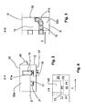
- Figure 1 illustrates a packaging machine 1 (not illustrated in its entirety) according to one embodiment of the present invention for producing filled, finished packages in the form of carton bottles of the initially described type.
- the packaging machine 1 is adapted for gas phase sterilization of the carton bottles prior to filling, sealing and folding of the same.
- the packaging machine 1 comprises a preheating zone 3, a gassing zone 5, a venting zone 7, a filling zone 9, a sealing zone 11, a final folding zone 13 and a buffer zone 15.
- the packaging machine 1 comprises an endless conveyor 17 for transporting the carton bottles 19 through the various zones in a transport direction T, the conveyor running back through the packaging machine in a return direction which is essentially opposite to the transport direction T (not illustrated in figure 1 ).
- the zones 3-9 are arranged in a row at the end of which the sealing zone 11, the final folding zone 13 and the buffer zone 15 are arranged, as is illustrated in the figure.
- the buffer zone 15 extends below the final folding zone 13, between the final folding zone and the sealing zone 11 and behind the sealing zone 11 seen in the direction of figure 1 .
- the specific extension of the buffer zone 15 is illustrated in Swedish copending patent application filed by the applicant on the same date as the present application and titled "Packaging machine and packaging method II" (SE-0900910-1).
- SE-09009101 Swedish copending patent application filed by the applicant on the same date as the present application and titled "Packaging machine and packaging method II"
- SE-0900910110111 Swedish copending patent application filed by the applicant on the same date as the present application and titled "Packaging machine and packaging method II"
- SE-0900910110111 Swedish copending patent application filed by the applicant on the same date as the present application and titled "Packaging machine and packaging method II"
- the outfeed station 23 accommodates means (not illustrated) for collecting the folded packages from the final folding zone 13 and delivering them outside the packaging machine.
- the infeed and outfeed stations will not be described in detail herein.
- SE-0900908-5 Swedish copending patent application filed by the applicant on the same date as the present application and titled "Device for cleaned air provision" (SE-0900908-5), which application is hereby incorporated herein by reference.
- SE-0900908-5 Device for cleaned air provision
- the carton bottles 19 are fed, with their bottom ends 29 open, to the packaging machine 1 via the infeed station 21 where they are arranged upside-down, with their respective bottom end 29 directed upwards, in carrier means 31 attached to the conveyor 17. Arranged like this, the carton bottles are then moved through the zones 3, 5 and 7 for sterilization. In the gassing zone 5, the carton bottles 19 are exposed to gaseous hydrogen peroxide. In order to prevent the hydrogen peroxide from condensing on the surface of the carton bottles in the gassing zone 5, which impedes later removal, the carton bottles are heated up in the preheating zone 3 to a temperature above the dew point of the hydrogen peroxide gas.
- the carton bottles are subjected to sterile hot air in order to vent off hydrogen peroxide which remains in and on the carton bottles.
- This sterilization operation is described in more detail in Swedish copending patent application filed by the applicant on the same date as the present application and titled "A device and a method for sterilization of packages” (SE-0900907-7), which application is hereby incorporated herein by reference.
- an aseptic environment at least in an upper part of the packaging machine 1 from the venting zone 7 to the sealing zone 11, i.e. until the carton bottles 19 have been finally sealed.
- This upper part extends somewhere from above the conveyor 17 to the top of the packaging machine 1 and is arranged to receive the bottom ends 29 of the carton bottles 19 when these are conveyed through the apparatus 1.
- This upper part is called an aseptic zone, AZ, and is illustrated in figure 1 (scored area).
- the endless conveyor 17 with the carriers 31 is, after delivery of finished carton bottles at the outfeed station 23, arranged to travel back through the packaging machine to the infeed station 21 to be loaded with new unfinished carton bottles for treatment in the above described way, without being cleaned in between, except for in connection with scheduled, regular productions stops intended for machine cleaning and sterilization.
- the final folding zone 13 is one of the parts of the packaging machine where it is most difficult to maintain hygienic conditions. This is because of the final folding operation generating paper dust and other free particles that can disturb the hygiene inside the final folding zone, and also inside other parts of the machine, if preventive measures are not taken.
- the outfeed station 23 is another part of the packaging machine where it is relatively difficult to maintain hygienic conditions. This is because of the outfeed station being open towards the surroundings to allow package output, which surroundings not always are very clean. Thus, particles from the outside can disturb the desired conditions inside the outfeed station and the rest of the packaging machine if preventive measures are not taken. Further, if the packaging machine is not working properly, this is often due to a problem, such as a jam, in the final folding zone or the outfeed station, i.e. a malfunctioning of the means for performing the final folding operation or the package outfeed, which means will not be described herein. To take care of such a problem, an external fixing operation is often required. Such an external intervention can also disturb the hygiene inside the final folding zone, the outfeed station and other packaging machine parts if proper measures are not taken.
- Figure 2 schematically shows a cross section of the packaging machine 1 taken along the line A-A in figure 1 .
- Figure 3 schematically shows a part of a cross section of the packaging machine 1 taken along the line B-B in figure 1 , which part corresponds to the area of the final folding zone 13 and a part of the buffer zone 15.
- the packaging machine 1 comprises a separation device 33 (33a + 33b) for physically separating the final folding zone 13 from the rest of the zones.
- the separation device includes a first baffle 33a extending through the packaging machine 1 orthogonal to the transport direction T to delimit the final folding zone 13 from the buffer zone 15 in an essentially vertical direction.
- the first baffle 33a extends from a top wall 35 and a predetermined distance towards a bottom wall 37 and all the way from one side wall S to the other side wall S' of the packaging machine 1.
- the separation device includes a second baffle 33b extending through the packaging machine 1 parallel to the transport direction T to delimit the final folding zone 13 from the buffer zone 15 in an essentially horizontal direction.
- the second baffle 33b is arranged very slightly angled in relation to the horizontal direction, which will not be further discussed herein.
- the second baffle 33b is connected to the first baffle 33a and extends therefrom all the way to a plate 39 separating the buffer zone 15 from the outfeed station 23 and all the way from one side wall S to the other side wall S' of the packaging machine 1.
- the plate 39 extends all the way from the top wall 35 to the bottom wall 37 and from the side wall S to the other side wall S' of the packaging machine.
- the plate has an opening (not illustrated) to the outfeed station 23.
- the separation device 33 has an opening 41 (41a+41b) to allow passage of the carton bottles 19 through the final folding zone 13.
- the opening is preferably as small as possible and adapted to the particular shape of the packages and the path of the conveyor.
- the opening 41 extends through both the first and the second baffle, 33a and 33b, respectively.
- the first baffle 33a it has the form of a rectangular slot 41 a extending from a connection line 43 between the baffles a predetermined distance towards the top wall 35 of the packaging machine 1.
- the second baffle 33b it has the form of a J-shaped slot 41b extending from the connection line 43 to the plate 39. Since the carriers 31 are empty after package output at the outfeed station 23, no slot is necessary for the return direction of the conveyor.
- the sealing zone 11 is separated from the buffer zone 15 by a wall of the duct 27 of the arrangement 25.
- the conveyor 17 is arranged to run outside the final folding zone 13 and instead through the buffer zone 15 to transport the carton bottles 19 through the final folding zone.
- the conveyor runs below the second baffle 33b and follows the slot 41 b formed therein so that the carton bottles, when arranged in the carriers 31 on the conveyor, protrudes through the slot and into the final folding zone 13. How big part of the carton bottles that protrudes into the final folding zone is naturally dependent upon the distance between the conveyor and the second baffle.
- the packaging machine comprises a hatch 45 (shown only in figures 2 and 4 ) in the area of the final folding zone 13 for easy external access to the same.
- This hatch consists of a section of the side wall S, which section is hinged at the top wall 35 of the packaging machine 1.
- the hatch 45 is illustrated in figure 2 in its opened position and in figure 4 in its closed position.
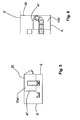
- Figure 4 is similar to figure 1 but shows only the part of the packaging machine 1 corresponding to the final folding zone 13, a part of the buffer zone 15 and the outfeed station 23 in a non-opened-up condition.
- the hatch 45 is closed.
- the hatch 45 can easily be opened for quick access to the final folding zone, and thereby the final folding means, for smooth remedy of the error.
- the above mentioned arrangement 25 for sterile air supply together with the separation device 33, the plate 39 and the wall of the duct 27 generate pressure differences inside the packaging machine 1. More particularly, a first pressure P1 is maintained inside the sealing zone 11 and a third pressure P3 maintained inside the buffer zone 15 is higher than a second pressure P2 maintained inside the final folding zone 13 which is higher than a fifth pressure P5 maintained inside the outfeed station 23, which in turn is higher than a fourth pressure P4 prevailing outside the packaging machine 1. Further, the pressure inside the sealing zone is higher than the pressure inside the buffer zone which means that the following condition is fulfilled: P1>P3>P2>P5>P4.
- sealing zone ⁇ buffer zone ⁇ final folding zone ⁇ outfeed station ⁇ machine surroundings When the hatch is open, the following flow will instead prevail: sealing zone ⁇ buffer zone ⁇ final folding zone ⁇ machine surroundings (possibly via the outfeed station).
- the hatch is formed as a part of the side wall of the packaging machine.
- the hatch could of course be constructed in alternative ways. It could, e.g. be formed as a part of the top wall of the packaging machine.
- the separation device comprised in the packaging machine according to the present inventions need not be designed in the above specified way.
- the baffles could be slightly separated.
- the baffles could also be slightly separated from the side, top, bottom and end walls of the packaging machine.
- the separation device could also comprise one single baffle with a configuration adapted for achievement of the desired object, or more than two baffles interacting in an appropriate way.
- the baffles need not be orientated in the above specified way.
- the baffles could be arranged inclined in relation to the transport direction and a direction orthogonal thereto, respectively.
- the extension of the final folding zone is defined by the baffles, the plate and the side and top walls of the packaging machine.
- the packaging machine could comprise additional baffles for defining the extension of the final folding zone.
- the packaging machine could comprise a third baffle 47 arranged essentially perpendicular to first and second baffles 33a' and 33b' (with alternative designs), respectively, i.e. essentially parallel to the side walls S and S', respectively, of the packaging machine, as is illustrated in figures 5 and 6 .
- This third baffle 47 could extend from the first baffle 33a' to the plate 39 and from the second baffle 33b' to the top wall 35 of the packaging machine.
- the buffer zone encloses the final forming zone on two sides, the buffer zone separating the final forming zone from the bottom wall of the packaging machine in the vertical direction and from the sealing zone in the horizontal direction.
- the first baffle 33a could be arranged close to the wall of the duct 27 to so that the buffer zone would not exist between the sealing and final folding zones and the final folding zone would communicate directly with sealing zone.
- inventive packaging machine may of course be used for producing other packages than carton bottles.
Landscapes
- Health & Medical Sciences (AREA)
- Mechanical Engineering (AREA)
- Engineering & Computer Science (AREA)
- Epidemiology (AREA)
- General Chemical & Material Sciences (AREA)
- Chemical Kinetics & Catalysis (AREA)
- Chemical & Material Sciences (AREA)
- Life Sciences & Earth Sciences (AREA)
- Animal Behavior & Ethology (AREA)
- General Health & Medical Sciences (AREA)
- Public Health (AREA)
- Veterinary Medicine (AREA)
- Auxiliary Devices For And Details Of Packaging Control (AREA)
- Basic Packing Technique (AREA)
- Vacuum Packaging (AREA)
Claims (15)
- Verpackungsmaschine (1), die eine Befüllungszone (9) zum Befüllen von Packstücken (19) durch ein jeweiliges offenes Ende (29) davon, eine Versiegelungszone (11) zum Versiegeln des jeweiligen offenen Endes der Packstücke nach dem Befüllen, eine Endfaltzone (13) zum Formen der Packstücke nach dem Versiegeln sowie eine Fördereinrichtung (17) zum Transportieren der Packstücke durch die Zonen in einer Transportrichtung (T) umfasst, dadurch gekennzeichnet, dass
die Fördereinrichtung so angeordnet ist, dass sie sich außerhalb der Endfaltzone befindet und stattdessen durch eine Pufferzone (15) verläuft, um die Packstücke durch die Endfaltzone zu transportieren, und
sie weiterhin Mittel zum Aufrechterhalten eines ersten Drucks (P1) im Innern der Versiegelungszone, eines zweiten Drucks (P2) im Innern der Endfaltzone sowie eines dritten Drucks (P3) im Innern der Pufferzone umfasst, wobei der erste und der dritte Druck höher als der zweite Druck sind, der wiederum höher als ein vierter Druck (P4) ist, der außerhalb der Verpackungsmaschine herrscht. - Verpackungsmaschine (1) nach Anspruch 1, die weiterhin eine Ausschleusungsstation (23) zum Ausschleusen der versiegelten, befüllten und geformten Packstücke (19) umfasst, wobei die Mittel weiterhin vorgesehen sind, um einen fünften Druck (P5) im Innern der Ausschleusungsstation aufrechtzuerhalten, der höher als der außerhalb der Verpackungsmaschine herrschende vierte Druck (P4) und niedriger als der zweite und dritte Druck (P2 und P3) im Innern der Endfaltzone (13) bzw. der Pufferzone (15) ist.
- Verpackungsmaschine (1) nach einem der vorstehend aufgeführten Ansprüche, bei der die Endfaltzone (13) einen oberen Teil davon und die Pufferzone (15) einen unteren Teil davon belegt, wobei der untere Teil unterhalb des oberen Teils angeordnet ist.
- Verpackungsmaschine (1) nach Anspruch 3, bei der die Pufferzone (15) auch einen Abschnitt davon belegt, der zwischen der Versiegelungszone (11) und dem oberen und unteren Teil davon angeordnet ist, wobei die Pufferzone die Endfaltzone (13) von der Versiegelungszone abgrenzt.
- Verpackungsmaschine (1) nach einem der vorstehend aufgeführten Ansprüche, bei der die Mittel eine Zuführungsvorrichtung (25), um der Verpackungsmaschine außerhalb der Endfaltzone (13) einen Strom gereinigter Luft zuzuführen, sowie eine Trennvorrichtung (33) beinhalten, um die Endfaltzone von den restlichen Zonen technisch abzugrenzen, wobei die Trennvorrichtung eine Öffnung (41) hat, die ein Passieren der Packstücke (19) durch die Endfaltzone ermöglicht.
- Verpackungsmaschine (1) nach Anspruch 5, bei der die Trennvorrichtung (33) ein erstes Prallblech (33a, 33a') und ein zweites Prallblech (33b, 33b') umfasst, um die Endfaltzone (13) von der Pufferzone (15) abzugrenzen.
- Verpackungsmaschine (1) nach Anspruch 6, bei der sich das erste Prallblech (33a, 33a') im Wesentlichen rechtwinklig zur Transportrichtung (T) und das zweite Prallblech (33b, 33b') sich im Wesentlichen parallel zur Transportrichtung (T) erstrecken.
- Verpackungsmaschine (1) nach einem der Ansprüche 6 oder 7, bei der das erste Prallblech (33a, 33a') sich von einer oberen Wand (35) hin zu einer Bodenwand (37) davon erstreckt, während das zweite Prallblech (33b, 33b') sich vom ersten Prallblech aus in der Transportrichtung (T) erstreckt.
- Verpackungsmaschine (1) nach einem der Ansprüche 6 bis 8, bei der das erste Prallblech (33a) und das zweite Prallblech (33b) sich im Wesentlichen über die gesamte Erstreckung von einer Seitenwand (S) zu einer anderen Seitenwand (S') der Verpackungsmaschine erstrecken.
- Verpackungsmaschine (1) nach einem der vorstehend aufgeführten Ansprüche, die weiterhin eine Luke (45) in einem Bereich der Endfaltzone (13) umfasst, um einen externen Zugang dazu zu ermöglichen.
- Verpackungsverfahren, das das Befüllen, in einer Befüllungszone (9), von Packstücken (19) durch ein jeweiliges offenes Ende (29) davon, das Versiegeln, in einer Versiegelungszone (11), des jeweiligen offenen Endes der Packstücke nach dem Befüllen, das Formen, in einer Endfaltzone (13), der Packstücke nach dem Versiegeln sowie das Transportieren der Packstücke auf einer Fördereinrichtung (17) durch die Zonen in einer Transportrichtung (T) umfasst, wobei die Zonen in einer Verpackungsmaschine (1) zusammengefasst sind, dadurch gekennzeichnet, dass es weiterhin Folgendes umfasst:Verlaufen der Fördereinrichtung außerhalb der Endfaltzone und stattdessen Verlaufen dieser Einrichtung durch eine Pufferzone (15), um die Packstücke durch die Endfaltzone zu transportieren, undAufrechterhalten eines ersten Drucks (P1) im Innern der Versiegelungszone, eines zweiten Drucks (P2) im Innern der Endfaltzone sowie eines dritten Drucks (P3) im Innern der Pufferzone, wobei der erste und der dritte Druck höher als der zweite Druck sind, der wiederum höher als ein vierter Druck (P4) ist, der außerhalb der Verpackungsmaschine herrscht.
- Verpackungsverfahren nach Anspruch 11, das weiterhin, an einer Ausschleusungsstation (23), das Ausschleusen der versiegelten, befüllten und geformten Packstücke (19) sowie das Aufrechterhalten eines fünften Drucks (P5) im Innern der Ausschleusungsstation umfasst, der höher als der außerhalb der Verpackungsmaschine herrschende vierte Druck (P4) und niedriger als der zweite und dritte Druck (P2 und P3) im Innern der Endfaltzone (13) bzw. der Pufferzone (15) ist.
- Verpackungsverfahren nach einem der Ansprüche 11 oder 12, das das Zuführen eines Stroms gereinigter Luft zur Verpackungsmaschine (1) außerhalb der Endfaltzone (13) sowie das Bereitstellen einer Trennvorrichtung (33) zur technischen Abgrenzung der Endfaltzone von den restlichen Zonen umfasst, wobei die Trennvorrichtung eine Öffnung (41) hat, die das Passieren der Packstücke (19) durch die Endfaltzone ermöglicht.
- Verpackungsverfahren nach Anspruch 13, bei dem die Trennvorrichtung (33) ein erstes Prallblech (33a) und ein zweites Prallblech (33b) zur Abgrenzung der Endfaltzone (13) von der Pufferzone (15) umfasst.
- Verpackungsverfahren nach einem der Ansprüche 11 - 14, das weiterhin das Bereitstellen einer Luke (45) in einem Bereich der Endfaltzone (13) umfasst, um einen externen Zugang dazu zu ermöglichen.
Applications Claiming Priority (2)
| Application Number | Priority Date | Filing Date | Title |
|---|---|---|---|
| SE0900909 | 2009-07-03 | ||
| PCT/SE2010/000181 WO2011002384A1 (en) | 2009-07-03 | 2010-06-24 | Packaging machine and packaging method |
Publications (3)
| Publication Number | Publication Date |
|---|---|
| EP2448828A1 EP2448828A1 (de) | 2012-05-09 |
| EP2448828A4 EP2448828A4 (de) | 2012-12-12 |
| EP2448828B1 true EP2448828B1 (de) | 2013-12-11 |
Family
ID=43411275
Family Applications (1)
| Application Number | Title | Priority Date | Filing Date |
|---|---|---|---|
| EP10794442.3A Not-in-force EP2448828B1 (de) | 2009-07-03 | 2010-06-24 | Verpackungsmaschine und verpackungsverfahren |
Country Status (9)
| Country | Link |
|---|---|
| EP (1) | EP2448828B1 (de) |
| CN (1) | CN102470940B (de) |
| AR (1) | AR077752A1 (de) |
| ES (1) | ES2444781T3 (de) |
| MX (1) | MX2011012953A (de) |
| RU (1) | RU2530506C2 (de) |
| SA (1) | SA110310552B1 (de) |
| UA (1) | UA104035C2 (de) |
| WO (1) | WO2011002384A1 (de) |
Families Citing this family (1)
| Publication number | Priority date | Publication date | Assignee | Title |
|---|---|---|---|---|
| ITBO20130294A1 (it) * | 2013-06-12 | 2014-12-13 | Gd Spa | Macchina impacchettatrice e metodo di incarto per utilizzare un incarto di sigarette sigillato con atmosfera modificata. |
Family Cites Families (13)
| Publication number | Priority date | Publication date | Assignee | Title |
|---|---|---|---|---|
| SE313147B (de) * | 1966-03-07 | 1969-08-04 | Tepar Ag | |
| IT1174497B (it) * | 1984-02-17 | 1987-07-01 | Prot Srl | Apparecchiatura per sterilizzare in continuo contenitore per l'industria farmaceutica del tipo a tunnel |
| DE3607322A1 (de) * | 1986-03-06 | 1987-09-10 | Bosch Gmbh Robert | Vorrichtung zum keimfreien verpacken |
| NL8701293A (nl) * | 1987-06-03 | 1989-01-02 | Johann Ludwig Van Der Vecht | Werkwijze voor het steriel verpakken van een produkt in houders, alsmede inrichting voor het uitvoeren van deze werkwijze. |
| US5350568A (en) * | 1992-11-09 | 1994-09-27 | Tetra Alfa Holdings, S.A. | Method and apparatus for sterilizing cartons and breaking carton score lines |
| US5865010A (en) * | 1997-03-28 | 1999-02-02 | Tetra Laval Holdings & Finance Sa | Filling machine having a compartmentalized clean air system enclosing the filling system thereof |
| SE511117C2 (sv) * | 1997-12-09 | 1999-08-09 | Tetra Laval Holdings & Finance | Sätt och anordning vid en förpackningsmaskin |
| DK1050467T3 (da) * | 1999-05-03 | 2004-06-07 | Tetra Laval Holdings & Finance | Enhed til sterilisering af banemateriale på en emballeringsmaskine til emballering af hældbare födevarer og emballeringsmaskine omfattende en sådan enhed |
| JP2001018909A (ja) * | 1999-07-07 | 2001-01-23 | Nihon Tetra Pak Kk | フラッシング装置 |
| SE524497C2 (sv) * | 2002-12-13 | 2004-08-17 | Tetra Laval Holdings & Finance | Steriliseringsanordning |
| DE102004012113A1 (de) * | 2004-03-12 | 2005-09-22 | Gasti-Verpackungsmaschinen Gmbh | Behälterfüllmaschine |
| FR2882341B1 (fr) * | 2005-02-23 | 2009-11-20 | Serac Group | Installation de conditionnement aseptique a zones tampon aseptiques |
| ITBO20080626A1 (it) * | 2008-10-13 | 2010-04-14 | Acma S P A | Metodo per la formazione ed il riempimento di contenitori ad uso alimentare |
-
2010
- 2010-06-24 EP EP10794442.3A patent/EP2448828B1/de not_active Not-in-force
- 2010-06-24 ES ES10794442.3T patent/ES2444781T3/es active Active
- 2010-06-24 UA UAA201201091A patent/UA104035C2/ru unknown
- 2010-06-24 CN CN201080024834.6A patent/CN102470940B/zh active Active
- 2010-06-24 MX MX2011012953A patent/MX2011012953A/es active IP Right Grant
- 2010-06-24 WO PCT/SE2010/000181 patent/WO2011002384A1/en not_active Ceased
- 2010-06-24 RU RU2012103654/13A patent/RU2530506C2/ru not_active IP Right Cessation
- 2010-06-30 SA SA110310552A patent/SA110310552B1/ar unknown
- 2010-07-02 AR ARP100102383A patent/AR077752A1/es not_active Application Discontinuation
Also Published As
| Publication number | Publication date |
|---|---|
| EP2448828A4 (de) | 2012-12-12 |
| SA110310552B1 (ar) | 2014-02-16 |
| ES2444781T3 (es) | 2014-02-26 |
| RU2530506C2 (ru) | 2014-10-10 |
| AR077752A1 (es) | 2011-09-21 |
| UA104035C2 (ru) | 2013-12-25 |
| WO2011002384A1 (en) | 2011-01-06 |
| CN102470940A (zh) | 2012-05-23 |
| EP2448828A1 (de) | 2012-05-09 |
| RU2012103654A (ru) | 2013-08-10 |
| CN102470940B (zh) | 2014-05-07 |
| MX2011012953A (es) | 2011-12-16 |
Similar Documents
| Publication | Publication Date | Title |
|---|---|---|
| JP6560316B2 (ja) | ボトル詰めライン及び方法 | |
| US20150143777A1 (en) | Packaging assembly, in particular cartoning assembly | |
| JP2015535500A (ja) | ボトル詰めライン及び方法 | |
| CN105377699A (zh) | 用于展开、填充并密封包装箱套的设备和方法 | |
| US10766653B2 (en) | Method of packaging sterilized products | |
| EP2448830B1 (de) | Verpackungsmaschine und verpackungsverfahren | |
| EP2448828B1 (de) | Verpackungsmaschine und verpackungsverfahren | |
| MX2010003386A (es) | Metodo y dispositivo para llenar contenedores de tipo plegable. | |
| CN102341308B (zh) | 填充机及在填充机中提供卫生环境的方法 | |
| JP7635218B2 (ja) | 衛生チャンバを備えた充填機 | |
| CN102470941B (zh) | 用于提供清洁空气的设备 | |
| US20070044436A1 (en) | Equipment and method for the packaging of packets of products in bags | |
| US12539994B2 (en) | Multi-bagger centrifugal organizer | |
| US20240253839A1 (en) | Multi-bagger linear organizer | |
| JP2731615B2 (ja) | 包装容器及び無菌包装方法 | |
| JPH06102450B2 (ja) | 紙製容器の充▲填▼包装装置 | |
| HK1165768B (en) | Filling machine and method for providing a hygienic environment in a filling machine |
Legal Events
| Date | Code | Title | Description |
|---|---|---|---|
| PUAI | Public reference made under article 153(3) epc to a published international application that has entered the european phase |
Free format text: ORIGINAL CODE: 0009012 |
|
| 17P | Request for examination filed |
Effective date: 20111114 |
|
| AK | Designated contracting states |
Kind code of ref document: A1 Designated state(s): AL AT BE BG CH CY CZ DE DK EE ES FI FR GB GR HR HU IE IS IT LI LT LU LV MC MK MT NL NO PL PT RO SE SI SK SM TR |
|
| DAX | Request for extension of the european patent (deleted) | ||
| A4 | Supplementary search report drawn up and despatched |
Effective date: 20121114 |
|
| RIC1 | Information provided on ipc code assigned before grant |
Ipc: B65B 55/02 20060101ALI20121108BHEP Ipc: B65B 31/02 20060101AFI20121108BHEP Ipc: B65B 55/10 20060101ALI20121108BHEP Ipc: A61L 2/20 20060101ALI20121108BHEP |
|
| RIC1 | Information provided on ipc code assigned before grant |
Ipc: B65B 55/02 20060101ALI20130618BHEP Ipc: A61L 2/20 20060101ALI20130618BHEP Ipc: B65B 31/02 20060101AFI20130618BHEP Ipc: B65B 55/10 20060101ALI20130618BHEP |
|
| GRAP | Despatch of communication of intention to grant a patent |
Free format text: ORIGINAL CODE: EPIDOSNIGR1 |
|
| INTG | Intention to grant announced |
Effective date: 20130807 |
|
| RIN1 | Information on inventor provided before grant (corrected) |
Inventor name: LINDBLAD, ULF Inventor name: OLSSON, JENNY |
|
| GRAS | Grant fee paid |
Free format text: ORIGINAL CODE: EPIDOSNIGR3 |
|
| GRAA | (expected) grant |
Free format text: ORIGINAL CODE: 0009210 |
|
| AK | Designated contracting states |
Kind code of ref document: B1 Designated state(s): AL AT BE BG CH CY CZ DE DK EE ES FI FR GB GR HR HU IE IS IT LI LT LU LV MC MK MT NL NO PL PT RO SE SI SK SM TR |
|
| REG | Reference to a national code |
Ref country code: GB Ref legal event code: FG4D |
|
| REG | Reference to a national code |
Ref country code: CH Ref legal event code: EP |
|
| REG | Reference to a national code |
Ref country code: AT Ref legal event code: REF Ref document number: 644421 Country of ref document: AT Kind code of ref document: T Effective date: 20140115 |
|
| REG | Reference to a national code |
Ref country code: IE Ref legal event code: FG4D |
|
| REG | Reference to a national code |
Ref country code: DE Ref legal event code: R096 Ref document number: 602010012440 Country of ref document: DE Effective date: 20140206 |
|
| REG | Reference to a national code |
Ref country code: ES Ref legal event code: FG2A Ref document number: 2444781 Country of ref document: ES Kind code of ref document: T3 Effective date: 20140226 |
|
| REG | Reference to a national code |
Ref country code: NO Ref legal event code: T2 Effective date: 20131211 |
|
| REG | Reference to a national code |
Ref country code: NL Ref legal event code: VDEP Effective date: 20131211 |
|
| REG | Reference to a national code |
Ref country code: AT Ref legal event code: MK05 Ref document number: 644421 Country of ref document: AT Kind code of ref document: T Effective date: 20131211 |
|
| PG25 | Lapsed in a contracting state [announced via postgrant information from national office to epo] |
Ref country code: LT Free format text: LAPSE BECAUSE OF FAILURE TO SUBMIT A TRANSLATION OF THE DESCRIPTION OR TO PAY THE FEE WITHIN THE PRESCRIBED TIME-LIMIT Effective date: 20131211 Ref country code: SE Free format text: LAPSE BECAUSE OF FAILURE TO SUBMIT A TRANSLATION OF THE DESCRIPTION OR TO PAY THE FEE WITHIN THE PRESCRIBED TIME-LIMIT Effective date: 20131211 Ref country code: HR Free format text: LAPSE BECAUSE OF FAILURE TO SUBMIT A TRANSLATION OF THE DESCRIPTION OR TO PAY THE FEE WITHIN THE PRESCRIBED TIME-LIMIT Effective date: 20131211 Ref country code: FI Free format text: LAPSE BECAUSE OF FAILURE TO SUBMIT A TRANSLATION OF THE DESCRIPTION OR TO PAY THE FEE WITHIN THE PRESCRIBED TIME-LIMIT Effective date: 20131211 Ref country code: NL Free format text: LAPSE BECAUSE OF FAILURE TO SUBMIT A TRANSLATION OF THE DESCRIPTION OR TO PAY THE FEE WITHIN THE PRESCRIBED TIME-LIMIT Effective date: 20131211 |
|
| REG | Reference to a national code |
Ref country code: LT Ref legal event code: MG4D |
|
| PG25 | Lapsed in a contracting state [announced via postgrant information from national office to epo] |
Ref country code: LV Free format text: LAPSE BECAUSE OF FAILURE TO SUBMIT A TRANSLATION OF THE DESCRIPTION OR TO PAY THE FEE WITHIN THE PRESCRIBED TIME-LIMIT Effective date: 20131211 Ref country code: AT Free format text: LAPSE BECAUSE OF FAILURE TO SUBMIT A TRANSLATION OF THE DESCRIPTION OR TO PAY THE FEE WITHIN THE PRESCRIBED TIME-LIMIT Effective date: 20131211 Ref country code: CY Free format text: LAPSE BECAUSE OF FAILURE TO SUBMIT A TRANSLATION OF THE DESCRIPTION OR TO PAY THE FEE WITHIN THE PRESCRIBED TIME-LIMIT Effective date: 20131211 |
|
| PG25 | Lapsed in a contracting state [announced via postgrant information from national office to epo] |
Ref country code: BE Free format text: LAPSE BECAUSE OF FAILURE TO SUBMIT A TRANSLATION OF THE DESCRIPTION OR TO PAY THE FEE WITHIN THE PRESCRIBED TIME-LIMIT Effective date: 20131211 Ref country code: IS Free format text: LAPSE BECAUSE OF FAILURE TO SUBMIT A TRANSLATION OF THE DESCRIPTION OR TO PAY THE FEE WITHIN THE PRESCRIBED TIME-LIMIT Effective date: 20140411 Ref country code: EE Free format text: LAPSE BECAUSE OF FAILURE TO SUBMIT A TRANSLATION OF THE DESCRIPTION OR TO PAY THE FEE WITHIN THE PRESCRIBED TIME-LIMIT Effective date: 20131211 |
|
| PG25 | Lapsed in a contracting state [announced via postgrant information from national office to epo] |
Ref country code: PL Free format text: LAPSE BECAUSE OF FAILURE TO SUBMIT A TRANSLATION OF THE DESCRIPTION OR TO PAY THE FEE WITHIN THE PRESCRIBED TIME-LIMIT Effective date: 20131211 Ref country code: RO Free format text: LAPSE BECAUSE OF FAILURE TO SUBMIT A TRANSLATION OF THE DESCRIPTION OR TO PAY THE FEE WITHIN THE PRESCRIBED TIME-LIMIT Effective date: 20131211 Ref country code: PT Free format text: LAPSE BECAUSE OF FAILURE TO SUBMIT A TRANSLATION OF THE DESCRIPTION OR TO PAY THE FEE WITHIN THE PRESCRIBED TIME-LIMIT Effective date: 20140411 Ref country code: SK Free format text: LAPSE BECAUSE OF FAILURE TO SUBMIT A TRANSLATION OF THE DESCRIPTION OR TO PAY THE FEE WITHIN THE PRESCRIBED TIME-LIMIT Effective date: 20131211 Ref country code: CZ Free format text: LAPSE BECAUSE OF FAILURE TO SUBMIT A TRANSLATION OF THE DESCRIPTION OR TO PAY THE FEE WITHIN THE PRESCRIBED TIME-LIMIT Effective date: 20131211 |
|
| REG | Reference to a national code |
Ref country code: DE Ref legal event code: R097 Ref document number: 602010012440 Country of ref document: DE |
|
| PLBE | No opposition filed within time limit |
Free format text: ORIGINAL CODE: 0009261 |
|
| STAA | Information on the status of an ep patent application or granted ep patent |
Free format text: STATUS: NO OPPOSITION FILED WITHIN TIME LIMIT |
|
| PG25 | Lapsed in a contracting state [announced via postgrant information from national office to epo] |
Ref country code: DK Free format text: LAPSE BECAUSE OF FAILURE TO SUBMIT A TRANSLATION OF THE DESCRIPTION OR TO PAY THE FEE WITHIN THE PRESCRIBED TIME-LIMIT Effective date: 20131211 |
|
| 26N | No opposition filed |
Effective date: 20140912 |
|
| REG | Reference to a national code |
Ref country code: DE Ref legal event code: R097 Ref document number: 602010012440 Country of ref document: DE Effective date: 20140912 |
|
| PG25 | Lapsed in a contracting state [announced via postgrant information from national office to epo] |
Ref country code: LU Free format text: LAPSE BECAUSE OF FAILURE TO SUBMIT A TRANSLATION OF THE DESCRIPTION OR TO PAY THE FEE WITHIN THE PRESCRIBED TIME-LIMIT Effective date: 20140624 Ref country code: MC Free format text: LAPSE BECAUSE OF FAILURE TO SUBMIT A TRANSLATION OF THE DESCRIPTION OR TO PAY THE FEE WITHIN THE PRESCRIBED TIME-LIMIT Effective date: 20131211 |
|
| REG | Reference to a national code |
Ref country code: CH Ref legal event code: PL |
|
| GBPC | Gb: european patent ceased through non-payment of renewal fee |
Effective date: 20140624 |
|
| PG25 | Lapsed in a contracting state [announced via postgrant information from national office to epo] |
Ref country code: SI Free format text: LAPSE BECAUSE OF FAILURE TO SUBMIT A TRANSLATION OF THE DESCRIPTION OR TO PAY THE FEE WITHIN THE PRESCRIBED TIME-LIMIT Effective date: 20131211 |
|
| REG | Reference to a national code |
Ref country code: IE Ref legal event code: MM4A |
|
| PG25 | Lapsed in a contracting state [announced via postgrant information from national office to epo] |
Ref country code: LI Free format text: LAPSE BECAUSE OF NON-PAYMENT OF DUE FEES Effective date: 20140630 Ref country code: IE Free format text: LAPSE BECAUSE OF NON-PAYMENT OF DUE FEES Effective date: 20140624 Ref country code: CH Free format text: LAPSE BECAUSE OF NON-PAYMENT OF DUE FEES Effective date: 20140630 |
|
| PG25 | Lapsed in a contracting state [announced via postgrant information from national office to epo] |
Ref country code: GB Free format text: LAPSE BECAUSE OF NON-PAYMENT OF DUE FEES Effective date: 20140624 |
|
| PG25 | Lapsed in a contracting state [announced via postgrant information from national office to epo] |
Ref country code: MT Free format text: LAPSE BECAUSE OF FAILURE TO SUBMIT A TRANSLATION OF THE DESCRIPTION OR TO PAY THE FEE WITHIN THE PRESCRIBED TIME-LIMIT Effective date: 20131211 |
|
| PG25 | Lapsed in a contracting state [announced via postgrant information from national office to epo] |
Ref country code: SM Free format text: LAPSE BECAUSE OF FAILURE TO SUBMIT A TRANSLATION OF THE DESCRIPTION OR TO PAY THE FEE WITHIN THE PRESCRIBED TIME-LIMIT Effective date: 20131211 |
|
| REG | Reference to a national code |
Ref country code: FR Ref legal event code: PLFP Year of fee payment: 7 |
|
| PG25 | Lapsed in a contracting state [announced via postgrant information from national office to epo] |
Ref country code: BG Free format text: LAPSE BECAUSE OF FAILURE TO SUBMIT A TRANSLATION OF THE DESCRIPTION OR TO PAY THE FEE WITHIN THE PRESCRIBED TIME-LIMIT Effective date: 20131211 Ref country code: GR Free format text: LAPSE BECAUSE OF FAILURE TO SUBMIT A TRANSLATION OF THE DESCRIPTION OR TO PAY THE FEE WITHIN THE PRESCRIBED TIME-LIMIT Effective date: 20140312 |
|
| PG25 | Lapsed in a contracting state [announced via postgrant information from national office to epo] |
Ref country code: HU Free format text: LAPSE BECAUSE OF FAILURE TO SUBMIT A TRANSLATION OF THE DESCRIPTION OR TO PAY THE FEE WITHIN THE PRESCRIBED TIME-LIMIT; INVALID AB INITIO Effective date: 20100624 Ref country code: TR Free format text: LAPSE BECAUSE OF FAILURE TO SUBMIT A TRANSLATION OF THE DESCRIPTION OR TO PAY THE FEE WITHIN THE PRESCRIBED TIME-LIMIT Effective date: 20131211 |
|
| REG | Reference to a national code |
Ref country code: FR Ref legal event code: PLFP Year of fee payment: 8 |
|
| REG | Reference to a national code |
Ref country code: FR Ref legal event code: PLFP Year of fee payment: 9 |
|
| PG25 | Lapsed in a contracting state [announced via postgrant information from national office to epo] |
Ref country code: MK Free format text: LAPSE BECAUSE OF FAILURE TO SUBMIT A TRANSLATION OF THE DESCRIPTION OR TO PAY THE FEE WITHIN THE PRESCRIBED TIME-LIMIT Effective date: 20131211 |
|
| PGFP | Annual fee paid to national office [announced via postgrant information from national office to epo] |
Ref country code: FR Payment date: 20180511 Year of fee payment: 9 |
|
| PG25 | Lapsed in a contracting state [announced via postgrant information from national office to epo] |
Ref country code: AL Free format text: LAPSE BECAUSE OF FAILURE TO SUBMIT A TRANSLATION OF THE DESCRIPTION OR TO PAY THE FEE WITHIN THE PRESCRIBED TIME-LIMIT Effective date: 20131211 |
|
| PGFP | Annual fee paid to national office [announced via postgrant information from national office to epo] |
Ref country code: ES Payment date: 20180703 Year of fee payment: 9 |
|
| PG25 | Lapsed in a contracting state [announced via postgrant information from national office to epo] |
Ref country code: FR Free format text: LAPSE BECAUSE OF NON-PAYMENT OF DUE FEES Effective date: 20190630 |
|
| REG | Reference to a national code |
Ref country code: ES Ref legal event code: FD2A Effective date: 20201029 |
|
| PG25 | Lapsed in a contracting state [announced via postgrant information from national office to epo] |
Ref country code: ES Free format text: LAPSE BECAUSE OF NON-PAYMENT OF DUE FEES Effective date: 20190625 |
|
| PGFP | Annual fee paid to national office [announced via postgrant information from national office to epo] |
Ref country code: NO Payment date: 20220617 Year of fee payment: 13 Ref country code: IT Payment date: 20220622 Year of fee payment: 13 |
|
| PGFP | Annual fee paid to national office [announced via postgrant information from national office to epo] |
Ref country code: DE Payment date: 20220628 Year of fee payment: 13 |
|
| P01 | Opt-out of the competence of the unified patent court (upc) registered |
Effective date: 20230426 |
|
| REG | Reference to a national code |
Ref country code: DE Ref legal event code: R119 Ref document number: 602010012440 Country of ref document: DE |
|
| REG | Reference to a national code |
Ref country code: NO Ref legal event code: MMEP |
|
| PG25 | Lapsed in a contracting state [announced via postgrant information from national office to epo] |
Ref country code: DE Free format text: LAPSE BECAUSE OF NON-PAYMENT OF DUE FEES Effective date: 20240103 |
|
| PG25 | Lapsed in a contracting state [announced via postgrant information from national office to epo] |
Ref country code: NO Free format text: LAPSE BECAUSE OF NON-PAYMENT OF DUE FEES Effective date: 20230630 |
|
| PG25 | Lapsed in a contracting state [announced via postgrant information from national office to epo] |
Ref country code: IT Free format text: LAPSE BECAUSE OF NON-PAYMENT OF DUE FEES Effective date: 20230624 |