EP2448047A1 - Hydrophilic porous layer for fuel cells, gas diffusion electrode and manufacturing method thereof, and membrane electrode assembly - Google Patents
Hydrophilic porous layer for fuel cells, gas diffusion electrode and manufacturing method thereof, and membrane electrode assembly Download PDFInfo
- Publication number
- EP2448047A1 EP2448047A1 EP10792188A EP10792188A EP2448047A1 EP 2448047 A1 EP2448047 A1 EP 2448047A1 EP 10792188 A EP10792188 A EP 10792188A EP 10792188 A EP10792188 A EP 10792188A EP 2448047 A1 EP2448047 A1 EP 2448047A1
- Authority
- EP
- European Patent Office
- Prior art keywords
- hydrophilic
- electrically conductive
- layer
- gas diffusion
- porous layer
- Prior art date
- Legal status (The legal status is an assumption and is not a legal conclusion. Google has not performed a legal analysis and makes no representation as to the accuracy of the status listed.)
- Withdrawn
Links
- 239000000446 fuel Substances 0.000 title claims abstract description 53
- 238000009792 diffusion process Methods 0.000 title claims description 131
- 239000012528 membrane Substances 0.000 title claims description 108
- 238000004519 manufacturing process Methods 0.000 title description 25
- XLYOFNOQVPJJNP-UHFFFAOYSA-N water Substances O XLYOFNOQVPJJNP-UHFFFAOYSA-N 0.000 claims abstract description 234
- 239000000463 material Substances 0.000 claims abstract description 212
- 239000004020 conductor Substances 0.000 claims abstract description 155
- 239000003054 catalyst Substances 0.000 claims description 167
- 239000011148 porous material Substances 0.000 claims description 62
- 238000000034 method Methods 0.000 claims description 59
- 239000007788 liquid Substances 0.000 claims description 43
- 239000002245 particle Substances 0.000 claims description 43
- 239000002904 solvent Substances 0.000 claims description 34
- 238000001035 drying Methods 0.000 claims description 14
- 230000000694 effects Effects 0.000 claims description 12
- 239000003795 chemical substances by application Substances 0.000 claims description 11
- 239000011163 secondary particle Substances 0.000 claims description 9
- 239000011164 primary particle Substances 0.000 claims description 6
- 238000010306 acid treatment Methods 0.000 claims description 5
- 229910044991 metal oxide Inorganic materials 0.000 claims description 4
- 150000004706 metal oxides Chemical class 0.000 claims description 4
- 230000004907 flux Effects 0.000 claims description 3
- 229920001477 hydrophilic polymer Polymers 0.000 claims description 3
- 229920006395 saturated elastomer Polymers 0.000 claims description 2
- 239000010410 layer Substances 0.000 description 343
- 239000007789 gas Substances 0.000 description 123
- OKTJSMMVPCPJKN-UHFFFAOYSA-N Carbon Chemical compound [C] OKTJSMMVPCPJKN-UHFFFAOYSA-N 0.000 description 69
- 239000000976 ink Substances 0.000 description 67
- 210000004027 cell Anatomy 0.000 description 57
- 239000003792 electrolyte Substances 0.000 description 45
- 229910052799 carbon Inorganic materials 0.000 description 37
- 239000002585 base Substances 0.000 description 33
- 229920000867 polyelectrolyte Polymers 0.000 description 28
- IJGRMHOSHXDMSA-UHFFFAOYSA-N Atomic nitrogen Chemical compound N#N IJGRMHOSHXDMSA-UHFFFAOYSA-N 0.000 description 21
- DNIAPMSPPWPWGF-UHFFFAOYSA-N Propylene glycol Chemical compound CC(O)CO DNIAPMSPPWPWGF-UHFFFAOYSA-N 0.000 description 18
- 230000002940 repellent Effects 0.000 description 17
- 239000005871 repellent Substances 0.000 description 17
- 238000009835 boiling Methods 0.000 description 16
- BASFCYQUMIYNBI-UHFFFAOYSA-N platinum Substances [Pt] BASFCYQUMIYNBI-UHFFFAOYSA-N 0.000 description 15
- 239000005518 polymer electrolyte Substances 0.000 description 15
- 239000000243 solution Substances 0.000 description 15
- 239000011230 binding agent Substances 0.000 description 14
- 229920000642 polymer Polymers 0.000 description 14
- 239000002253 acid Substances 0.000 description 13
- 239000003575 carbonaceous material Substances 0.000 description 13
- 238000009826 distribution Methods 0.000 description 13
- 238000002156 mixing Methods 0.000 description 13
- 239000000203 mixture Substances 0.000 description 13
- BDERNNFJNOPAEC-UHFFFAOYSA-N propan-1-ol Chemical compound CCCO BDERNNFJNOPAEC-UHFFFAOYSA-N 0.000 description 13
- LFQSCWFLJHTTHZ-UHFFFAOYSA-N Ethanol Chemical compound CCO LFQSCWFLJHTTHZ-UHFFFAOYSA-N 0.000 description 12
- OKKJLVBELUTLKV-UHFFFAOYSA-N Methanol Chemical compound OC OKKJLVBELUTLKV-UHFFFAOYSA-N 0.000 description 12
- 239000007791 liquid phase Substances 0.000 description 12
- 238000005259 measurement Methods 0.000 description 12
- 229920001343 polytetrafluoroethylene Polymers 0.000 description 12
- 239000004810 polytetrafluoroethylene Substances 0.000 description 12
- 229910052731 fluorine Inorganic materials 0.000 description 11
- 150000002500 ions Chemical class 0.000 description 11
- 238000006722 reduction reaction Methods 0.000 description 11
- 238000010276 construction Methods 0.000 description 10
- 230000005611 electricity Effects 0.000 description 10
- 239000007787 solid Substances 0.000 description 10
- 239000012808 vapor phase Substances 0.000 description 10
- LYCAIKOWRPUZTN-UHFFFAOYSA-N Ethylene glycol Chemical compound OCCO LYCAIKOWRPUZTN-UHFFFAOYSA-N 0.000 description 9
- YCKRFDGAMUMZLT-UHFFFAOYSA-N Fluorine atom Chemical compound [F] YCKRFDGAMUMZLT-UHFFFAOYSA-N 0.000 description 9
- KFZMGEQAYNKOFK-UHFFFAOYSA-N Isopropanol Chemical compound CC(C)O KFZMGEQAYNKOFK-UHFFFAOYSA-N 0.000 description 9
- -1 Ketchen Black Chemical compound 0.000 description 9
- 239000011737 fluorine Substances 0.000 description 9
- 229910052757 nitrogen Inorganic materials 0.000 description 9
- 229920005989 resin Polymers 0.000 description 9
- 239000011347 resin Substances 0.000 description 9
- 239000006230 acetylene black Substances 0.000 description 8
- 239000006229 carbon black Substances 0.000 description 8
- 210000000170 cell membrane Anatomy 0.000 description 8
- 229910052751 metal Inorganic materials 0.000 description 8
- 239000003960 organic solvent Substances 0.000 description 8
- 239000000523 sample Substances 0.000 description 8
- 239000000126 substance Substances 0.000 description 8
- LSNNMFCWUKXFEE-UHFFFAOYSA-M Bisulfite Chemical compound OS([O-])=O LSNNMFCWUKXFEE-UHFFFAOYSA-M 0.000 description 7
- 238000001704 evaporation Methods 0.000 description 7
- 230000008020 evaporation Effects 0.000 description 7
- 238000010438 heat treatment Methods 0.000 description 7
- 239000002184 metal Substances 0.000 description 7
- 238000007254 oxidation reaction Methods 0.000 description 7
- PEDCQBHIVMGVHV-UHFFFAOYSA-N Glycerine Chemical compound OCC(O)CO PEDCQBHIVMGVHV-UHFFFAOYSA-N 0.000 description 6
- UFHFLCQGNIYNRP-UHFFFAOYSA-N Hydrogen Chemical compound [H][H] UFHFLCQGNIYNRP-UHFFFAOYSA-N 0.000 description 6
- 229920000557 Nafion® Polymers 0.000 description 6
- QVGXLLKOCUKJST-UHFFFAOYSA-N atomic oxygen Chemical compound [O] QVGXLLKOCUKJST-UHFFFAOYSA-N 0.000 description 6
- 238000006555 catalytic reaction Methods 0.000 description 6
- 238000007599 discharging Methods 0.000 description 6
- 239000001257 hydrogen Substances 0.000 description 6
- 229910052739 hydrogen Inorganic materials 0.000 description 6
- QSHDDOUJBYECFT-UHFFFAOYSA-N mercury Chemical compound [Hg] QSHDDOUJBYECFT-UHFFFAOYSA-N 0.000 description 6
- 229910052753 mercury Inorganic materials 0.000 description 6
- VNWKTOKETHGBQD-UHFFFAOYSA-N methane Chemical compound C VNWKTOKETHGBQD-UHFFFAOYSA-N 0.000 description 6
- 239000001301 oxygen Substances 0.000 description 6
- 229910052760 oxygen Inorganic materials 0.000 description 6
- 229910052697 platinum Inorganic materials 0.000 description 6
- 229920000049 Carbon (fiber) Polymers 0.000 description 5
- 229910045601 alloy Inorganic materials 0.000 description 5
- 239000000956 alloy Substances 0.000 description 5
- 150000001721 carbon Chemical group 0.000 description 5
- 239000004917 carbon fiber Substances 0.000 description 5
- 230000008859 change Effects 0.000 description 5
- 239000006185 dispersion Substances 0.000 description 5
- 239000007792 gaseous phase Substances 0.000 description 5
- 238000005087 graphitization Methods 0.000 description 5
- 229920000554 ionomer Polymers 0.000 description 5
- 239000000843 powder Substances 0.000 description 5
- 230000009467 reduction Effects 0.000 description 5
- PUPZLCDOIYMWBV-UHFFFAOYSA-N (+/-)-1,3-Butanediol Chemical compound CC(O)CCO PUPZLCDOIYMWBV-UHFFFAOYSA-N 0.000 description 4
- 239000004215 Carbon black (E152) Substances 0.000 description 4
- 239000002033 PVDF binder Substances 0.000 description 4
- NBIIXXVUZAFLBC-UHFFFAOYSA-N Phosphoric acid Chemical compound OP(O)(O)=O NBIIXXVUZAFLBC-UHFFFAOYSA-N 0.000 description 4
- 239000000654 additive Substances 0.000 description 4
- 239000012298 atmosphere Substances 0.000 description 4
- WERYXYBDKMZEQL-UHFFFAOYSA-N butane-1,4-diol Chemical compound OCCCCO WERYXYBDKMZEQL-UHFFFAOYSA-N 0.000 description 4
- 239000002270 dispersing agent Substances 0.000 description 4
- 125000001153 fluoro group Chemical group F* 0.000 description 4
- 239000002737 fuel gas Substances 0.000 description 4
- 229930195733 hydrocarbon Natural products 0.000 description 4
- 150000002430 hydrocarbons Chemical class 0.000 description 4
- 150000002739 metals Chemical group 0.000 description 4
- 239000007800 oxidant agent Substances 0.000 description 4
- 230000003647 oxidation Effects 0.000 description 4
- 239000012071 phase Substances 0.000 description 4
- 229920002981 polyvinylidene fluoride Polymers 0.000 description 4
- 238000001179 sorption measurement Methods 0.000 description 4
- 239000007921 spray Substances 0.000 description 4
- 125000000542 sulfonic acid group Chemical group 0.000 description 4
- QTBSBXVTEAMEQO-UHFFFAOYSA-N Acetic acid Chemical compound CC(O)=O QTBSBXVTEAMEQO-UHFFFAOYSA-N 0.000 description 3
- LRHPLDYGYMQRHN-UHFFFAOYSA-N N-Butanol Chemical compound CCCCO LRHPLDYGYMQRHN-UHFFFAOYSA-N 0.000 description 3
- 238000010521 absorption reaction Methods 0.000 description 3
- 230000000996 additive effect Effects 0.000 description 3
- 230000015572 biosynthetic process Effects 0.000 description 3
- 238000006243 chemical reaction Methods 0.000 description 3
- 230000007797 corrosion Effects 0.000 description 3
- 238000005260 corrosion Methods 0.000 description 3
- 229910001873 dinitrogen Inorganic materials 0.000 description 3
- 229920001971 elastomer Polymers 0.000 description 3
- 230000008014 freezing Effects 0.000 description 3
- 238000007710 freezing Methods 0.000 description 3
- 229910002804 graphite Inorganic materials 0.000 description 3
- 239000010439 graphite Substances 0.000 description 3
- 238000007731 hot pressing Methods 0.000 description 3
- 239000002861 polymer material Substances 0.000 description 3
- 239000005060 rubber Substances 0.000 description 3
- 239000002002 slurry Substances 0.000 description 3
- 238000010023 transfer printing Methods 0.000 description 3
- 238000005303 weighing Methods 0.000 description 3
- 229940083957 1,2-butanediol Drugs 0.000 description 2
- CSCPPACGZOOCGX-UHFFFAOYSA-N Acetone Chemical compound CC(C)=O CSCPPACGZOOCGX-UHFFFAOYSA-N 0.000 description 2
- 229920003935 Flemion® Polymers 0.000 description 2
- KRHYYFGTRYWZRS-UHFFFAOYSA-N Fluorane Chemical compound F KRHYYFGTRYWZRS-UHFFFAOYSA-N 0.000 description 2
- VEXZGXHMUGYJMC-UHFFFAOYSA-N Hydrochloric acid Chemical compound Cl VEXZGXHMUGYJMC-UHFFFAOYSA-N 0.000 description 2
- XEEYBQQBJWHFJM-UHFFFAOYSA-N Iron Chemical compound [Fe] XEEYBQQBJWHFJM-UHFFFAOYSA-N 0.000 description 2
- SECXISVLQFMRJM-UHFFFAOYSA-N N-Methylpyrrolidone Chemical compound CN1CCCC1=O SECXISVLQFMRJM-UHFFFAOYSA-N 0.000 description 2
- AMQJEAYHLZJPGS-UHFFFAOYSA-N N-Pentanol Chemical compound CCCCCO AMQJEAYHLZJPGS-UHFFFAOYSA-N 0.000 description 2
- PXHVJJICTQNCMI-UHFFFAOYSA-N Nickel Chemical compound [Ni] PXHVJJICTQNCMI-UHFFFAOYSA-N 0.000 description 2
- KDLHZDBZIXYQEI-UHFFFAOYSA-N Palladium Chemical compound [Pd] KDLHZDBZIXYQEI-UHFFFAOYSA-N 0.000 description 2
- ABLZXFCXXLZCGV-UHFFFAOYSA-N Phosphorous acid Chemical compound OP(O)=O ABLZXFCXXLZCGV-UHFFFAOYSA-N 0.000 description 2
- 239000004696 Poly ether ether ketone Substances 0.000 description 2
- 229910001260 Pt alloy Inorganic materials 0.000 description 2
- QAOWNCQODCNURD-UHFFFAOYSA-N Sulfuric acid Chemical compound OS(O)(=O)=O QAOWNCQODCNURD-UHFFFAOYSA-N 0.000 description 2
- 238000002441 X-ray diffraction Methods 0.000 description 2
- 239000012790 adhesive layer Substances 0.000 description 2
- 229910052782 aluminium Inorganic materials 0.000 description 2
- 229910000147 aluminium phosphate Inorganic materials 0.000 description 2
- 238000004458 analytical method Methods 0.000 description 2
- 229910021383 artificial graphite Inorganic materials 0.000 description 2
- 230000005540 biological transmission Effects 0.000 description 2
- BMRWNKZVCUKKSR-UHFFFAOYSA-N butane-1,2-diol Chemical compound CCC(O)CO BMRWNKZVCUKKSR-UHFFFAOYSA-N 0.000 description 2
- 235000019437 butane-1,3-diol Nutrition 0.000 description 2
- 229910021393 carbon nanotube Inorganic materials 0.000 description 2
- 239000002041 carbon nanotube Substances 0.000 description 2
- 239000006231 channel black Substances 0.000 description 2
- 239000000084 colloidal system Substances 0.000 description 2
- 239000000470 constituent Substances 0.000 description 2
- 239000013078 crystal Substances 0.000 description 2
- 230000001186 cumulative effect Effects 0.000 description 2
- 238000000354 decomposition reaction Methods 0.000 description 2
- 238000003795 desorption Methods 0.000 description 2
- 238000003411 electrode reaction Methods 0.000 description 2
- 238000011049 filling Methods 0.000 description 2
- 238000010304 firing Methods 0.000 description 2
- UQSQSQZYBQSBJZ-UHFFFAOYSA-N fluorosulfonic acid Chemical compound OS(F)(=O)=O UQSQSQZYBQSBJZ-UHFFFAOYSA-N 0.000 description 2
- 150000002431 hydrogen Chemical class 0.000 description 2
- 238000005470 impregnation Methods 0.000 description 2
- 230000006872 improvement Effects 0.000 description 2
- 238000009616 inductively coupled plasma Methods 0.000 description 2
- 230000000977 initiatory effect Effects 0.000 description 2
- 239000006233 lamp black Substances 0.000 description 2
- BDAGIHXWWSANSR-UHFFFAOYSA-N methanoic acid Natural products OC=O BDAGIHXWWSANSR-UHFFFAOYSA-N 0.000 description 2
- 239000000693 micelle Substances 0.000 description 2
- 239000004530 micro-emulsion Substances 0.000 description 2
- 239000002116 nanohorn Substances 0.000 description 2
- 229910021382 natural graphite Inorganic materials 0.000 description 2
- 229910052755 nonmetal Inorganic materials 0.000 description 2
- JYVLIDXNZAXMDK-UHFFFAOYSA-N pentan-2-ol Chemical compound CCCC(C)O JYVLIDXNZAXMDK-UHFFFAOYSA-N 0.000 description 2
- AQIXEPGDORPWBJ-UHFFFAOYSA-N pentan-3-ol Chemical compound CCC(O)CC AQIXEPGDORPWBJ-UHFFFAOYSA-N 0.000 description 2
- 229920002401 polyacrylamide Polymers 0.000 description 2
- 229920002530 polyetherether ketone Polymers 0.000 description 2
- 229920000139 polyethylene terephthalate Polymers 0.000 description 2
- 239000005020 polyethylene terephthalate Substances 0.000 description 2
- 238000010248 power generation Methods 0.000 description 2
- 238000007650 screen-printing Methods 0.000 description 2
- 238000007789 sealing Methods 0.000 description 2
- 239000010935 stainless steel Substances 0.000 description 2
- 229910001220 stainless steel Inorganic materials 0.000 description 2
- TXEYQDLBPFQVAA-UHFFFAOYSA-N tetrafluoromethane Chemical compound FC(F)(F)F TXEYQDLBPFQVAA-UHFFFAOYSA-N 0.000 description 2
- 239000006234 thermal black Substances 0.000 description 2
- QHGNHLZPVBIIPX-UHFFFAOYSA-N tin(ii) oxide Chemical compound [Sn]=O QHGNHLZPVBIIPX-UHFFFAOYSA-N 0.000 description 2
- 229910052719 titanium Inorganic materials 0.000 description 2
- 239000010936 titanium Substances 0.000 description 2
- SUTQSIHGGHVXFK-UHFFFAOYSA-N 1,2,2-trifluoroethenylbenzene Chemical compound FC(F)=C(F)C1=CC=CC=C1 SUTQSIHGGHVXFK-UHFFFAOYSA-N 0.000 description 1
- NWUYHJFMYQTDRP-UHFFFAOYSA-N 1,2-bis(ethenyl)benzene;1-ethenyl-2-ethylbenzene;styrene Chemical compound C=CC1=CC=CC=C1.CCC1=CC=CC=C1C=C.C=CC1=CC=CC=C1C=C NWUYHJFMYQTDRP-UHFFFAOYSA-N 0.000 description 1
- PAKNPEMFWIUWQV-UHFFFAOYSA-N 1,2-difluoro-2-(2-fluorophenyl)ethenesulfonic acid Chemical compound OS(=O)(=O)C(F)=C(F)C1=CC=CC=C1F PAKNPEMFWIUWQV-UHFFFAOYSA-N 0.000 description 1
- OSWFIVFLDKOXQC-UHFFFAOYSA-N 4-(3-methoxyphenyl)aniline Chemical compound COC1=CC=CC(C=2C=CC(N)=CC=2)=C1 OSWFIVFLDKOXQC-UHFFFAOYSA-N 0.000 description 1
- 229920003934 Aciplex® Polymers 0.000 description 1
- XMWRBQBLMFGWIX-UHFFFAOYSA-N C60 fullerene Chemical compound C12=C3C(C4=C56)=C7C8=C5C5=C9C%10=C6C6=C4C1=C1C4=C6C6=C%10C%10=C9C9=C%11C5=C8C5=C8C7=C3C3=C7C2=C1C1=C2C4=C6C4=C%10C6=C9C9=C%11C5=C5C8=C3C3=C7C1=C1C2=C4C6=C2C9=C5C3=C12 XMWRBQBLMFGWIX-UHFFFAOYSA-N 0.000 description 1
- VYZAMTAEIAYCRO-UHFFFAOYSA-N Chromium Chemical compound [Cr] VYZAMTAEIAYCRO-UHFFFAOYSA-N 0.000 description 1
- IAZDPXIOMUYVGZ-UHFFFAOYSA-N Dimethylsulphoxide Chemical compound CS(C)=O IAZDPXIOMUYVGZ-UHFFFAOYSA-N 0.000 description 1
- 229920002943 EPDM rubber Polymers 0.000 description 1
- VGGSQFUCUMXWEO-UHFFFAOYSA-N Ethene Chemical compound C=C VGGSQFUCUMXWEO-UHFFFAOYSA-N 0.000 description 1
- 239000005977 Ethylene Substances 0.000 description 1
- 229920000181 Ethylene propylene rubber Polymers 0.000 description 1
- 206010016275 Fear Diseases 0.000 description 1
- KRHYYFGTRYWZRS-UHFFFAOYSA-M Fluoride anion Chemical compound [F-] KRHYYFGTRYWZRS-UHFFFAOYSA-M 0.000 description 1
- GYHNNYVSQQEPJS-UHFFFAOYSA-N Gallium Chemical compound [Ga] GYHNNYVSQQEPJS-UHFFFAOYSA-N 0.000 description 1
- ZOKXTWBITQBERF-UHFFFAOYSA-N Molybdenum Chemical compound [Mo] ZOKXTWBITQBERF-UHFFFAOYSA-N 0.000 description 1
- GRYLNZFGIOXLOG-UHFFFAOYSA-N Nitric acid Chemical compound O[N+]([O-])=O GRYLNZFGIOXLOG-UHFFFAOYSA-N 0.000 description 1
- IOVCWXUNBOPUCH-UHFFFAOYSA-N Nitrous acid Chemical compound ON=O IOVCWXUNBOPUCH-UHFFFAOYSA-N 0.000 description 1
- 239000004698 Polyethylene Substances 0.000 description 1
- 229920002367 Polyisobutene Polymers 0.000 description 1
- KJTLSVCANCCWHF-UHFFFAOYSA-N Ruthenium Chemical compound [Ru] KJTLSVCANCCWHF-UHFFFAOYSA-N 0.000 description 1
- 229920002125 Sokalan® Polymers 0.000 description 1
- 239000004809 Teflon Substances 0.000 description 1
- 229920006362 Teflon® Polymers 0.000 description 1
- GWEVSGVZZGPLCZ-UHFFFAOYSA-N Titan oxide Chemical compound O=[Ti]=O GWEVSGVZZGPLCZ-UHFFFAOYSA-N 0.000 description 1
- 150000007513 acids Chemical class 0.000 description 1
- 230000009471 action Effects 0.000 description 1
- 239000011149 active material Substances 0.000 description 1
- 238000005054 agglomeration Methods 0.000 description 1
- 230000002776 aggregation Effects 0.000 description 1
- 150000001298 alcohols Chemical class 0.000 description 1
- 239000003513 alkali Substances 0.000 description 1
- XAGFODPZIPBFFR-UHFFFAOYSA-N aluminium Chemical compound [Al] XAGFODPZIPBFFR-UHFFFAOYSA-N 0.000 description 1
- MAHPNPYYQAIOJN-UHFFFAOYSA-N azimsulfuron Chemical compound COC1=CC(OC)=NC(NC(=O)NS(=O)(=O)C=2N(N=CC=2C2=NN(C)N=N2)C)=N1 MAHPNPYYQAIOJN-UHFFFAOYSA-N 0.000 description 1
- 229920005601 base polymer Polymers 0.000 description 1
- 239000011324 bead Substances 0.000 description 1
- 238000004364 calculation method Methods 0.000 description 1
- 239000002134 carbon nanofiber Substances 0.000 description 1
- 229910052804 chromium Inorganic materials 0.000 description 1
- 239000011651 chromium Substances 0.000 description 1
- 238000004140 cleaning Methods 0.000 description 1
- 229910017052 cobalt Inorganic materials 0.000 description 1
- 239000010941 cobalt Substances 0.000 description 1
- GUTLYIVDDKVIGB-UHFFFAOYSA-N cobalt atom Chemical compound [Co] GUTLYIVDDKVIGB-UHFFFAOYSA-N 0.000 description 1
- 239000000571 coke Substances 0.000 description 1
- 230000000052 comparative effect Effects 0.000 description 1
- 150000001875 compounds Chemical class 0.000 description 1
- 230000003750 conditioning effect Effects 0.000 description 1
- 229920001940 conductive polymer Polymers 0.000 description 1
- 239000002826 coolant Substances 0.000 description 1
- 229920001577 copolymer Polymers 0.000 description 1
- 229910052802 copper Inorganic materials 0.000 description 1
- 239000010949 copper Substances 0.000 description 1
- 230000003247 decreasing effect Effects 0.000 description 1
- 239000002612 dispersion medium Substances 0.000 description 1
- 238000007606 doctor blade method Methods 0.000 description 1
- 238000003487 electrochemical reaction Methods 0.000 description 1
- 230000007613 environmental effect Effects 0.000 description 1
- 229920001038 ethylene copolymer Polymers 0.000 description 1
- 125000000816 ethylene group Chemical group [H]C([H])([*:1])C([H])([H])[*:2] 0.000 description 1
- 239000006023 eutectic alloy Substances 0.000 description 1
- 238000011156 evaluation Methods 0.000 description 1
- 230000001747 exhibiting effect Effects 0.000 description 1
- 238000002474 experimental method Methods 0.000 description 1
- 239000004744 fabric Substances 0.000 description 1
- 239000012530 fluid Substances 0.000 description 1
- 235000019253 formic acid Nutrition 0.000 description 1
- 229910003472 fullerene Inorganic materials 0.000 description 1
- 239000007849 furan resin Substances 0.000 description 1
- 239000006232 furnace black Substances 0.000 description 1
- 229910052733 gallium Inorganic materials 0.000 description 1
- 229910052737 gold Inorganic materials 0.000 description 1
- 239000010931 gold Substances 0.000 description 1
- 239000012535 impurity Substances 0.000 description 1
- AMGQUBHHOARCQH-UHFFFAOYSA-N indium;oxotin Chemical compound [In].[Sn]=O AMGQUBHHOARCQH-UHFFFAOYSA-N 0.000 description 1
- 239000011261 inert gas Substances 0.000 description 1
- 229910000765 intermetallic Inorganic materials 0.000 description 1
- 238000005342 ion exchange Methods 0.000 description 1
- 239000003456 ion exchange resin Substances 0.000 description 1
- 229920003303 ion-exchange polymer Polymers 0.000 description 1
- 239000002608 ionic liquid Substances 0.000 description 1
- 229910052741 iridium Inorganic materials 0.000 description 1
- GKOZUEZYRPOHIO-UHFFFAOYSA-N iridium atom Chemical compound [Ir] GKOZUEZYRPOHIO-UHFFFAOYSA-N 0.000 description 1
- 229910052742 iron Inorganic materials 0.000 description 1
- 239000011133 lead Substances 0.000 description 1
- 239000011244 liquid electrolyte Substances 0.000 description 1
- WPBNNNQJVZRUHP-UHFFFAOYSA-L manganese(2+);methyl n-[[2-(methoxycarbonylcarbamothioylamino)phenyl]carbamothioyl]carbamate;n-[2-(sulfidocarbothioylamino)ethyl]carbamodithioate Chemical compound [Mn+2].[S-]C(=S)NCCNC([S-])=S.COC(=O)NC(=S)NC1=CC=CC=C1NC(=S)NC(=O)OC WPBNNNQJVZRUHP-UHFFFAOYSA-L 0.000 description 1
- 239000007769 metal material Substances 0.000 description 1
- 239000013528 metallic particle Substances 0.000 description 1
- 150000007522 mineralic acids Chemical class 0.000 description 1
- 229910052750 molybdenum Inorganic materials 0.000 description 1
- 239000011733 molybdenum Substances 0.000 description 1
- 229910052759 nickel Inorganic materials 0.000 description 1
- 229910017604 nitric acid Inorganic materials 0.000 description 1
- 239000004745 nonwoven fabric Substances 0.000 description 1
- 150000007524 organic acids Chemical class 0.000 description 1
- 150000002894 organic compounds Chemical class 0.000 description 1
- 229910052762 osmium Inorganic materials 0.000 description 1
- SYQBFIAQOQZEGI-UHFFFAOYSA-N osmium atom Chemical compound [Os] SYQBFIAQOQZEGI-UHFFFAOYSA-N 0.000 description 1
- RVTZCBVAJQQJTK-UHFFFAOYSA-N oxygen(2-);zirconium(4+) Chemical compound [O-2].[O-2].[Zr+4] RVTZCBVAJQQJTK-UHFFFAOYSA-N 0.000 description 1
- 229910052763 palladium Inorganic materials 0.000 description 1
- 230000002093 peripheral effect Effects 0.000 description 1
- 239000005011 phenolic resin Substances 0.000 description 1
- 229920000172 poly(styrenesulfonic acid) Polymers 0.000 description 1
- 239000004584 polyacrylic acid Substances 0.000 description 1
- 229920002239 polyacrylonitrile Polymers 0.000 description 1
- 229920000767 polyaniline Polymers 0.000 description 1
- 229920006260 polyaryletherketone Polymers 0.000 description 1
- 229920000573 polyethylene Polymers 0.000 description 1
- 239000011112 polyethylene naphthalate Substances 0.000 description 1
- 229920006389 polyphenyl polymer Polymers 0.000 description 1
- 229940005642 polystyrene sulfonic acid Drugs 0.000 description 1
- 229920000131 polyvinylidene Polymers 0.000 description 1
- 239000002243 precursor Substances 0.000 description 1
- 238000007639 printing Methods 0.000 description 1
- 230000008569 process Effects 0.000 description 1
- 230000002035 prolonged effect Effects 0.000 description 1
- 238000010926 purge Methods 0.000 description 1
- 239000012495 reaction gas Substances 0.000 description 1
- 230000027756 respiratory electron transport chain Effects 0.000 description 1
- 229910052703 rhodium Inorganic materials 0.000 description 1
- 239000010948 rhodium Substances 0.000 description 1
- MHOVAHRLVXNVSD-UHFFFAOYSA-N rhodium atom Chemical compound [Rh] MHOVAHRLVXNVSD-UHFFFAOYSA-N 0.000 description 1
- 229910052707 ruthenium Inorganic materials 0.000 description 1
- 238000005070 sampling Methods 0.000 description 1
- 239000004576 sand Substances 0.000 description 1
- 229920002050 silicone resin Polymers 0.000 description 1
- 229920002379 silicone rubber Polymers 0.000 description 1
- 239000004945 silicone rubber Substances 0.000 description 1
- 239000006104 solid solution Substances 0.000 description 1
- 150000005846 sugar alcohols Polymers 0.000 description 1
- 238000004381 surface treatment Methods 0.000 description 1
- 238000012360 testing method Methods 0.000 description 1
- 229920002803 thermoplastic polyurethane Polymers 0.000 description 1
- 229910001887 tin oxide Inorganic materials 0.000 description 1
- OGIDPMRJRNCKJF-UHFFFAOYSA-N titanium oxide Inorganic materials [Ti]=O OGIDPMRJRNCKJF-UHFFFAOYSA-N 0.000 description 1
- WFKWXMTUELFFGS-UHFFFAOYSA-N tungsten Chemical compound [W] WFKWXMTUELFFGS-UHFFFAOYSA-N 0.000 description 1
- 229910052721 tungsten Inorganic materials 0.000 description 1
- 239000010937 tungsten Substances 0.000 description 1
- 238000009849 vacuum degassing Methods 0.000 description 1
- 238000001291 vacuum drying Methods 0.000 description 1
- 229910052720 vanadium Inorganic materials 0.000 description 1
- GPPXJZIENCGNKB-UHFFFAOYSA-N vanadium Chemical compound [V]#[V] GPPXJZIENCGNKB-UHFFFAOYSA-N 0.000 description 1
- 230000008016 vaporization Effects 0.000 description 1
- 229910001928 zirconium oxide Inorganic materials 0.000 description 1
Images






Classifications
-
- H—ELECTRICITY
- H01—ELECTRIC ELEMENTS
- H01M—PROCESSES OR MEANS, e.g. BATTERIES, FOR THE DIRECT CONVERSION OF CHEMICAL ENERGY INTO ELECTRICAL ENERGY
- H01M8/00—Fuel cells; Manufacture thereof
- H01M8/10—Fuel cells with solid electrolytes
- H01M8/1004—Fuel cells with solid electrolytes characterised by membrane-electrode assemblies [MEA]
-
- H—ELECTRICITY
- H01—ELECTRIC ELEMENTS
- H01M—PROCESSES OR MEANS, e.g. BATTERIES, FOR THE DIRECT CONVERSION OF CHEMICAL ENERGY INTO ELECTRICAL ENERGY
- H01M4/00—Electrodes
- H01M4/86—Inert electrodes with catalytic activity, e.g. for fuel cells
- H01M4/8605—Porous electrodes
-
- H—ELECTRICITY
- H01—ELECTRIC ELEMENTS
- H01M—PROCESSES OR MEANS, e.g. BATTERIES, FOR THE DIRECT CONVERSION OF CHEMICAL ENERGY INTO ELECTRICAL ENERGY
- H01M4/00—Electrodes
- H01M4/86—Inert electrodes with catalytic activity, e.g. for fuel cells
- H01M4/8647—Inert electrodes with catalytic activity, e.g. for fuel cells consisting of more than one material, e.g. consisting of composites
- H01M4/8652—Inert electrodes with catalytic activity, e.g. for fuel cells consisting of more than one material, e.g. consisting of composites as mixture
-
- H—ELECTRICITY
- H01—ELECTRIC ELEMENTS
- H01M—PROCESSES OR MEANS, e.g. BATTERIES, FOR THE DIRECT CONVERSION OF CHEMICAL ENERGY INTO ELECTRICAL ENERGY
- H01M8/00—Fuel cells; Manufacture thereof
- H01M8/02—Details
- H01M8/0202—Collectors; Separators, e.g. bipolar separators; Interconnectors
- H01M8/023—Porous and characterised by the material
- H01M8/0241—Composites
-
- Y—GENERAL TAGGING OF NEW TECHNOLOGICAL DEVELOPMENTS; GENERAL TAGGING OF CROSS-SECTIONAL TECHNOLOGIES SPANNING OVER SEVERAL SECTIONS OF THE IPC; TECHNICAL SUBJECTS COVERED BY FORMER USPC CROSS-REFERENCE ART COLLECTIONS [XRACs] AND DIGESTS
- Y02—TECHNOLOGIES OR APPLICATIONS FOR MITIGATION OR ADAPTATION AGAINST CLIMATE CHANGE
- Y02E—REDUCTION OF GREENHOUSE GAS [GHG] EMISSIONS, RELATED TO ENERGY GENERATION, TRANSMISSION OR DISTRIBUTION
- Y02E60/00—Enabling technologies; Technologies with a potential or indirect contribution to GHG emissions mitigation
- Y02E60/30—Hydrogen technology
- Y02E60/50—Fuel cells
-
- Y—GENERAL TAGGING OF NEW TECHNOLOGICAL DEVELOPMENTS; GENERAL TAGGING OF CROSS-SECTIONAL TECHNOLOGIES SPANNING OVER SEVERAL SECTIONS OF THE IPC; TECHNICAL SUBJECTS COVERED BY FORMER USPC CROSS-REFERENCE ART COLLECTIONS [XRACs] AND DIGESTS
- Y02—TECHNOLOGIES OR APPLICATIONS FOR MITIGATION OR ADAPTATION AGAINST CLIMATE CHANGE
- Y02P—CLIMATE CHANGE MITIGATION TECHNOLOGIES IN THE PRODUCTION OR PROCESSING OF GOODS
- Y02P70/00—Climate change mitigation technologies in the production process for final industrial or consumer products
- Y02P70/50—Manufacturing or production processes characterised by the final manufactured product
Definitions
- the present invention relates to a hydrophilic porous layer for a fuel cell, a gas diffusion electrode and a method of producing same and a membrane electrode assembly.
- Polymer electrolyte fuel cell has such features that the electrolyte is free of dissipation, the control of potential difference between electrodes is easy, the operating temperature is low allowing quick starting of the fuel cell, and a compact and light weight construction is possible.
- PEFC Polymer electrolyte fuel cell
- the following electrode reaction takes place, that is depicted by chemical formula 1.
- Patent Citation 1 shows one solution.
- a water retaining layer that promotes water retaining and a water repellent layer that promotes water-drainage.
- Patent Citation 1 discloses an electrode of polymer electrolyte fuel cell, in which each of the water retaining layer and the electrode catalyst layer includes crystalline carbon fiber and the water retaining layer includes water retaining material and electronically conductive material.
- Patent Citation 1 shows that irrespective of humidifying condition of reacting gas supplied to the fuel cell, the provision of the water retaining layer causes the cell to exhibit a stable and high electricity generating performance without being easily affected by humidity change.
- the present invention provides a MEA constituting element and a method of producing the same, which element is able to promote the water transportability particularly in a low temperature condition and improve a gas transportability. More specifically, the present invention provides a hydrophilic porous layer for a fuel cell and a method of producing the same, which layer comprises an electrolyte and an electrically conductive material and has a construction in which a covering condition of the electrolyte to the electrically conductive material and a structure of the layer are defined. With such invention, evaporation area is assured and undesired voltage drop caused by liquid water, which would occur at the time of operation starting under a low temperature (especially at sub-zero temperature), is suppressed.
- hydrophilic porous layer By the hydrophilic porous layer according to the present invention, sufficient evaporation area is assured, and undesired voltage drop caused by liquid water, which would occur at the time of operation starting under a lower temperature (especially at sub-zero temperature), is suppressed.
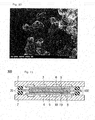
- a polymer electrolyte fuel cell has such a construction that an electrolyte membrane electrode assembly 1 (called also as membrane electrode assembly) is held by gas diffusion layers 13 (anode gas diffusion layer and cathode gas diffusion layer) and separators.
- an electrolyte membrane electrode assembly 1 (called also as membrane electrode assembly) is held by gas diffusion layers 13 (anode gas diffusion layer and cathode gas diffusion layer) and separators.
- gas diffusion layers 13 anode gas diffusion layer and cathode gas diffusion layer and separators.
- a catalyst layer called also as cathode catalyst layer or cathode catalyst electrode
- another catalyst layer called also as anode catalyst layer or anode catalyst electrode
- the catalyst layer and the gas diffusion layer are called as a diffusion electrode layer.
- the layer When provided at cathode side, the layer is called as a cathode diffusion electrode layer, and when provided at anode side, the layer is called as an anode diffusion electrode layer.
- the gas diffusion layer may comprise a micropore layer and a macropore layer (base). It is to be noted that terms used for indicating construction of polymer electrolyte fuel cell described in the specification and the above-described terms have identical definition therebetween.
- Fig. 1 it has been considered that water (mainly liquid water) produced at the cathode side is transported or discharged through two routes.
- One of the routes is a route in which after flowing through internal pores formed in the cathode micropore layer 14c and (cathode) macropore layer (cathode base) 15c, water is discharged into a cathode gas flow path 17 as liquid water or water vapor.
- the other one of the routes is a route in which after being transported toward the anode side through the electrolyte membrane and flowing through internal pores formed in an anode micropore layer 14a and (anode) macropore layer (anode base) 15a while leaving part of produced water kept in the anode catalyst layer 12a, water is discharged into an anode gas flow path 18 as liquid water or water vapor.
- the transport of the produced water in the anode or cathode catalyst layer and in the micropore layer is mainly made by the transport of water vapor in the internal pores, the transport of liquid water in the electrolyte and the transport of vaporized liquid water in the internal pores of the electrolyte.
- the water produced at the cathode side can be easily discharged as compared with the transport toward the anode side since the distance to the cathode gas flow path is relatively short.
- MEA membrane electrode assembly
- an important task that is a total water control, that includes control of humidification to the membrane, control of water produced in the cathode side and control of water that moves in the membrane has to be accomplished.
- One method of establishing the task is to promote transport of water toward the anode side.
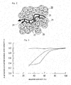
- One embodiment of the present invention is a layer that comprises aggregates of electrically conductive material and hydrophilic material in which the electrically conductive material and hydrophilic material of each aggregate closely contact to one another and the hydrophilic materials mutually connect to one another to form in the hydrophilic material a continuous transport path for water (liquid water) and in which the aggregates of electrically conductive material and hydrophilic material define therebetween a transport path for water vapor.
- the layer is a hydrophilic porous layer that is characterized in that at a temperature of -40°C (estimated lowest temperature), a water transport resistance R water of the above-mentioned water transport path is larger than a water vapor transport resistance R gas of the above-mentioned water vapor transport path.
- water flowing in the fuel cell catalyst layer has two modes, one being a mode in which the water flows in the form of water vapor (vapor phase) and the other being a mode in which the water flows in the form of liquid water (liquid phase).
- vapor phase water flows in the form of water vapor
- liquid phase liquid water
- water transport in the vapor phase is mainly carried out.
- a lower temperature especially, at sub-zero temperature
- water transport in the liquid phase largely contributes to the transport.
- the transport paths for liquid phase water are not sufficiently provided, and thus, it often happens that smoothed water transport throughout the system is prevented.
- hydrophilic material-conductive material aggregates 20 there are produced aggregates 20 of hydrophilic material-electrically conductive material (which will be referred to as hydrophilic material-conductive material aggregates 20 hereinafter). It is assumed that when plurality of hydrophilic material-conductive material aggregates 20 are collected, pores are formed due to a stereoscopic structure produced by the hydrophilic material-conductive material aggregates 20, and a water vapor transport path 23 is formed between mutually adjacent hydrophilic material-conductive material aggregates 20.
- the liquid water moving in the transport path 22 in the hydrophilic material is allowed to be exposed to the outside air for longer time. Accordingly, in the hydrophilic porous layer of the invention, as is indicated by 24 in Fig. 2 that shows routes from liquid water to water vapor, the liquid water can be quickly vaporized permitting water transport in the vapor phase. As a result, it can be considered that the water transportability of the entire system is increased.
- Fig. 2 shows a type in which outer surface of the electrically conductive material is applied with a catalyst component
- other types may be used which are for example a type in which only the electrically conductive material is used and a type in which the electrically conductive material and the electrically conductive material applied with the catalyst component are mixed.
- Diffusion coefficient D eff gas in an environment having therein the diffusions intermixed is determined in the following manner.
- the effective diffusion coefficient D eff gas is defined in the following manner.
- calculation of the transport resistance of water should be made under the condition that the transport is made using an activity difference as a driving force.
- a material such as Nafion (registered trademark) is used as the hydrophilic material
- the diffusion coefficient is measured using a contained-water amount ( ⁇ ) gradient of one unit of sulfonic acid group as the driving force.
- ⁇ contained-water amount
- the effective diffusion coefficient of the liquid water in the hydrophilic porous layer of the invention is represented by the following equation.
- Fig. 3 depicts the results of experiment of the hydrophilic porous layer of the invention showing the relationship between the relative humidity and electric double layer capacity.
- the electric double layer capacity is provided or formed by only a boundary surface between the electrically conductive material and the ion conductive hydrophilic material. With this, it is regarded that the transport path for water (liquid water) is continuously connected.
- an electric double layer capacity at a relative humidity of 40% and that at a relative humidity of 50% are compared, and if the rate of change is equal to or smaller than 10%, it is regarded that continuous water (liquid water) transport paths (viz., water transport paths that are continuously connected) are formed.
- the thickness of the hydrophilic porous layer of the invention thickness of 2 to 40 ⁇ m is preferable, and thickness of 2 to 25 ⁇ m is more preferable. If the thickness of the hydrophilic porous layer is within the above-mentioned range, both water transportability and gas diffusing capability are assured, and thus, the range is preferable. With usage of a mercury press-in method by which a pore distribution is measured, volume of pores (micropore) provided in the layer is measured, and porosity is derived as a percentage of the volume of pores relative to the volume of the layer.
- a porosity of an entire construction of the hydrophilic porous layer in the invention is not particularly limited, but 30 to 80% is preferable for it, and 40 to 70% is more preferable for it. When the porosity is within the above-mentioned range, the water transportability and gas diffusibility are assured and thus such range is preferable.
- the porosity can be derived by measuring the volume of pores (fine pores) placed in the layer by means of a fine pore distribution measurement using a mercury press-in method and calculating the ratio of the volume relative to a volume of the layer.
- the hydrophilic porous layer of the invention is a layer that comprises hydrophilic material and electrically conductive material. If desired, the electrically conductive material may be applied with a catalyst component.
- the hydrophilic material is preferably 50 to 150 parts by mass, more preferably 70 to 130 parts by mass relative to 100 parts by mass of the electrically conductive material.
- the hydrophilic material of the hydrophilic porous layer of the invention is smaller than 50 parts by mass relative to 100 parts by mass of the electrically conductive material, the mass ratio of the hydrophilic material relative to the electrically conductive material becomes low, so that it tends to occur that, due to intimate contact between mutually adjacent hydrophilic materials, formation or production of a continuous water (liquid water) transport path fails. While, if the hydrophilic material exceeds 150 parts by mass, it tends to occur that a water vapor transport path is not sufficiently provided and thus the water transportability of the entire system of the layer is lowered.
- the hydrophilic porous layer of the invention may contain other material other than the electrically conductive material and binder.
- the content of both the electrically conductive material and hydrophilic material is equal to or greater than 60% by volume, more preferably, equal to or greater than 80% by volume. More preferably, the hydrophilic porous layer comprises electrically conductive material and ion conductive material.
- the content of the catalyst component in the electrode catalyst is preferably 10 to 80 mass % and more preferably 30 to 70 mass %. If the content of the catalyst component in the electrode catalyst is smaller than 10 mass %, it tends to occur that due to reduction of outer surface of the catalyst, a sufficient power output is not obtained. While, if the content of the catalyst component exceeds 80% mass %, it tends to occur that due to exceeded agglomeration of catalyst particles, the outer surface of the catalyst relative to the amount of catalyst applied to the electrically conductive material is lowered.
- a sub-zero temperature starting can be carried out in a high current density operation. More specifically, in sub-zero temperature starting, undesired water freezing is suppressed due to increase of the water transportability, and thus, damage of a fuel cell caused by the water freezing and undesired voltage drop caused by lowering in gas diffusing capability are suppressed.
- Examples of electrically conductive material used in the invention are natural graphite, artificial graphite produced from organic compounds such as polyacrylonitrile, phenol resin, furan resin and the like, carbon materials such as activated carbon, carbon black (oil furnace black, furnace black, channel black, Ketchen Black, lamp black, thermal black, acetylene black and the like) and metal oxides such as oxides of Sn, Ti and the like. Carbon material is preferable.
- examples of the electrically conductive material are Vulcan (registered trademark) XC-72R produced by Cabot Corporation, Vulcan (registered trademark) P, Black Pearls (registered trademark) 1100, Black Pearls (registered trademark) 1300, Black Pearls (registered trademark) 2000, Regal (registered trademark) 400, Ketchen Black (registered trademark) EC produced by Ketchen Black International Corporation, Ketchen Black (registered trademark) EC600JD, and #3150 and #3250 produced by Mitsubishi Chemical Corporation.
- An example of acetylene black is Denka Black (registered trademark) produced by DENKI KAGAKU KOGYO KABUSHIKIKAISHA.
- the electrically conductive material used in the invention may be particulate, granular, needle-shaped, tabular, irregular-shaped particulate, fibrous, tubular, conical, megaphone-shaped, etc.,.
- the electrically conductive material may be a material to which aftertreatment has been applied.
- the electrically conductive material may be added with metallic particles of Au, Pt, Ti, Cu, Al or stainless steel, particles of stannous oxide, particles of indium tin oxide or electron conductive high polymers, such as polyaniline, fullerene or the like.
- the mean particle diameter (grain size) of the primary particles used in the invention is equal to or smaller than 60nm, and it is more preferable that the mean particle diameter is 5 to 50nm and most preferable that the mean particle diameter is 5 to 40nm.
- the mean particle diameter of the primary particles is equal to or smaller than 60nm, larger surface area can be obtained with a smaller amount of the material. As a result, the thickness of the hydrophilic porous layer proper of the invention can be reduced and thus the water transport resistance of the entire system can be reduced.
- the primary particle explained in the specification is directed to each of particles that form a flocculated cluster of the particles.
- the carbon material such as the above-mentioned carbon black is of a type that is flocculated.
- the particle diameter mentioned in the specification is the largest one "L” of the distances each being a distance between any two points on a contour of active material particle.
- the mean particle diameter the value of the mean particle diameter of the particles that are shown in several tens of viewing areas provided by a scanning electron microscope (SEM) or transmission electron microscope (TEM) is used.
- the electrically conductive material used in the invention is a material whose outer surface has been subjected to acid treatment.
- the hydrophilic site of the electrically conductive material is increased and thus the hydrophilic porous layer of the invention can have a larger water holding capacity thereby to promote the water discharge from the catalyst layer.
- Examples of the method of applying acid treatment to the outer surface of the electrically conductive material of the invention are a method in which the electrically conductive material is immersed in a known acid solution provided by inorganic acid such as hydrochloric acid, sulfuric acid, nitric acid, nitrous acid or sulfurous phosphoric acid, a method in which the electrically conductive material is immersed in acid solution provided by organic acid such as acetic acid, formic acid or hydrofluoric acid and a method in which the electrically conductive material is immersed in mixed acid of the above-mentioned acids and a method in which the acid solution is sprayed onto the electrically conductive material.
- inorganic acid such as hydrochloric acid, sulfuric acid, nitric acid, nitrous acid or sulfurous phosphoric acid
- organic acid such as acetic acid, formic acid or hydrofluoric acid
- the electrically conductive material is immersed in mixed acid of the above-mentioned acids and a method in which the acid solution is s
- the solvent used for the above-mentioned acid solution is mainly water. However, if it is desired to facilitate dispersion of the electrically conductive material in the solution, the solution may contain polarized organic solvent such as acetone, alcohol or the like.
- the concentration of the above-mentioned acid solution is not limited so long as it provides acid.
- the time for which the immersing is kept for providing the outer surface of the electrically conductive material of the invention with the hydrophilic site is not particularly limited. That is, the immersing time is suitably selected in accordance with "pH" of the acid solution, the size of the electrically conductive material, etc.,.
- the immersing time is suitably selected in accordance with "pH" of the acid solution, the size of the electrically conductive material, etc.,.
- One example is to immerse the electrically conductive material in a given amount of acid solution for 1 to 48 hours.
- acid may be removed from the electrically conductive material by making heat treatment, firing, cleaning, drying and so on.
- the temperature set for the heat treatment and firing is preferably 20 to 300°C.
- the hydrophilic material used in the invention is not particularly limited so long as it is ion-conductive and able to bond the electrically conductive material.
- Examples of the hydrophilic material are high polymers, such as polyacrylamide, water-based urethane resin and silicone resin and polyelectrolyte. Most preferable one is polyelectrolyte.
- the polyelectrolyte By denaturing the polyelectrolyte to the hydrophilic material, the polyelectrolyte can be stably arranged in case wherein the hydrophilic porous layer is arranged to adjoin a MEA constituent element (electrolyte membrane or catalyst layer) that contains identical hydrophilic material and ion-conductive material, so that the water transport resistance in a clearance defined between the electrically conductive material and each of the catalyst layer and electrolyte membrane can be reduced. As a result, the water transportability in the clearance between the electrically conductive material and each of the catalyst layer and the electrolyte membrane is improved, and thus, state of equilibrium is quickly achieved.
- a MEA constituent element electrophilic material and ion-conductive material
- the hydrophilic material is a polyelectrolyte
- the polyelectrolyte may be the same as or different from a polyelectrolyte used in the catalyst layer or the electrolyte membrane.
- MEA that includes hydrophilic porous layer
- the hydrophilic material suitably used in the invention is not particularly limited. Specifically, the hydrophilic material is roughly classified into fluorine-based electrolyte in which fluorine atom is contained in the whole or part of polymer frame and hydrocarbon-based electrolyte in which no fluorine atom is contained in polymer frame.
- the fluorine-based electrolyte include specifically perfluorocarbon sulfonic acid based polymer such as Nafion (registered trade name, produced by Dupont), Aciplex (trade name, produced by Asahi Kasei Chemicals Corporation), Flemion (registered trade name, produced by Asahi Glass Co., Ltd.) and the like, polytrifluorostyrene sulfonic acid based polymer, perfluorocarbon phosphonic acid based polymer, trifluorostyrene sulfonic acid based polymer, ethylenetetrafluoroethylene-g-styrene sulfonic acid based polymer, ethylene-trarafluoroethylene copolymer, polyvinylidene fluoride-perfluorocarbon sulfonic acid based polymer, and the like.
- the fluorine-based electrolyte is excellent in durability and mechanical strength.
- hydrocarbon-based electrolyte examples include preferably polyphosphonic acid, polyaryletherketone sulfonic acid, polybenzimidazoleaklyl sulfonic acid, polybenzimidazolealkyl phosphonic acid, polystyrene sulfonic acid, polyetheretherketone sulfonic acid, polyphenyl sulfonic acid, and the like.
- hydrophilic materials may be used single or in combination of two or more kinds.
- EW of the hydrophilic material is preferably low.
- EW is preferably not higher than 1200 g/eq., more preferably not higher than 1000 g/eq., and most preferably not higher than 700 g/eq. With such a range, diffusion of liquid water can be promoted thereby providing the hydrophilic porous layer which is compatible in a sub-zero temperature starting ability and a high current density operation at normal temperature.
- the lower limit of EW is not particularly limited, but it is preferable not lower than 500 g/eq. It is to be noted that EW (Equivalent Weight) represents an ion exchange group equivalent mass.
- the hydrophilic material used in the invention covers at least part of the above-mentioned electrically conductive material and a cover area S ion of the hydrophilic material to the electrically electrically conductive material is represented by the following equation.
- S ion S BET X ⁇ ion (In the above equation, S BET is BET nitrogen specific surface area of the electrically conductive material, and ⁇ ion is a covering ratio of the hydrophilic material.)
- the covering surface S ion of the hydrophilic material to a unit mass of the electrically conductive material is preferably not smaller than 200m 2 /g, and more preferably, not smaller than 200m 2 /g and not larger than 1600m 2 /g.
- the boundary surface between hydrophilic material and vapor phase is increased thereby to promote the phase change from liquid phase to vapor phase, and as a result of promotion of the phase change to vapor phase, the water transportability throughout the system is improved.
- cover area S ion of the hydrophilic material is not smaller than 200m 2 /g and not larger than 1600m 2 /g, discharge of liquid water can be promoted due to increase in vaporizing area.
- Fig. 4 is a schematic representation of an electrically conductive material 45 at least part of which is covered with a hydrophilic material 41, which is according to the present invention.
- a BET nitrogen specific surface area (S BET ) corresponds to the part of the broken line.
- a covering area (S ion ) 47 of the hydrophilic material which is an area (surface area) of the hydrophilic material that covers the electrically conductive material, corresponds to the part where the broken line 46 and a dot-dash line 48 that indicates an inside surface area of the hydrophilic material are overlapped. That is, the covering area (Sion) 47 of the hydrophilic material, which the area of the hydrophilic material that covers the electrically conductive material, is an area of the part where the electrically conductive material 45 and the hydrophilic material 41 contact to each other.
- the reason why the ratio between the relative humidity of 30% and the relative humidity of 100% is adopted is as follows. Under a high humidity condition, an electric double layer formed at an interface between the electrically conductive material and water adsorbed to the surface of the electrically conductive material or an electric double layer formed at an interface between the electrically conductive material and the hydrophilic material is measured.
- the relative humidity of 30% and that of 100% are made as representing points for the low humidity condition and high humidity condition and by obtaining a ratio between the electric double layer capacity at one representing point and that at the other representing point, an index of knowing how large that the electrically conductive material is covered with the hydrophilic material is obtained.
- the hydrophilic porous layer containing no catalyst component and the catalyst layer were respectively disposed at the different surfaces of an electrolyte membrane thereby producing the membrane electrode assembly.
- the assembly were interposed at its opposite surfaces between a pair of gas diffusion layers, further between carbon separators, and further between gold-plated collector plates thereby obtaining a cell similar to a usual fuel cell.
- the electric potential of the hydrophilic porous layer was scanned 5 to 10 times within a range of 0.2 to 0.6 V relative to a reference electrode using the catalyst layers respectively as the reference electrode and an opposite electrode. These scans were made at a scanning speed of 50 mV/s.
- Measuring apparatus High accuracy fully automatic gas absorption apparatus BELSORP36 produced by BEL Japan Inc. Absorbed gas: N2 Dead volume measurement gas: He Absorption temperature: 77 K (liquid nitrogen temperature) Measurement pretreatment: 90 °C vacuum drying for several hours (set at a measuring stage after He purging) Measuring mode: Adsorption step and desorption step at the same temperature Measuring relative pressure P/P 0 : about 0 to 0.99 Equilibrium setting time: 180 sec. for 1 relative pressure
- a BET plot is prepared from a range of about 0.00 to 0.45 in relative pressure (P/P 0 ) in an absorption side of an adsorption and desorption isothermal curve, upon which the BET nitrogen specific surface area is calculated from the inclination and segment of the plot.
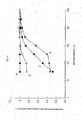
- Fig. 6 are a graph that depicts the property of various electrically conductive materials in terms of a relationship between the relative humidity and the electric double layer capacity and a table that indicates S BET , ⁇ ion and S ion of each of the electrically conductive materials.
- S BET S BET
- Carbon material A is Ketchen black EC (produced by Ketchen Black International Co., Ltd.); Carbon material B is a material which is prepared by making a heat treatment of 2000-3000 °C and 2 to 120 minutes to Ketchen black EC in an inert atmosphere; Carbon material C is acetylene black (SAB, produced by Denki Kagaku Kogyo Kabushiki Kaisha); and Carbon material D is acetylene black (OSAB, produced by Denki Kagaku Kogyo Kabushiki Kaisha).
- SAB acetylene black
- OSAB acetylene black
- the covering ratio ⁇ ion of the hydrophilic material used in the invention is within a range of ⁇ 20% of the maximum value of the covering ratio ⁇ ion of the hydrophilic material.
- the hydrophilic material effectively used in the hydrophilic porous layer is increased and thus the phase change to the vapor phase is promoted.
- the amount of the hydrophilic material in the system is increased, and thus, it is considered that the covering ratio ⁇ ion of the hydrophilic material, that corresponds to a contacting surface between the electrically conductive material and the hydrophilic material, is increased as a matter of course. That is, as is shown in the drawing of Fig. 5A , when the mass ratio between the hydrophilic material and the electrically conductive material is low, the covering ratio ⁇ ion that corresponds to the contacting surface between the electrically conductive material and the hydrophilic material is reduced.
- the hydrophilic material in the aggregates of electrically conductive material and hydrophilic material does not establish a mutually intimate contact thereamong thereby failing to form continuous liquid water transportation paths.
- the relationship between the mass ratio between the hydrophilic material and electrically conductive material and the covering ratio ⁇ ion of the hydrophilic material is so made that the covering ratio ⁇ ion of the hydrophilic material becomes constant once the mass ratio between the hydrophilic material and electrically conductive material exceeds a predetermined value.
- the covering ratio ⁇ ion of the hydrophilic material is within a range of ⁇ 20% of the maximum value of the covering ratio ⁇ ion of the hydrophilic material.
- the hydrophilic material and electrically conductive material make mutually intimate contact therebetween and the hydrophilic material establishes a mutually intimate contact thereamong thereby forming continuous liquid water transportation paths.
- the covering ratio ⁇ ion of the hydrophilic material is smaller than 0.7, and more preferable that the ratio is not smaller than 0.2 and smaller than 0.7, and much more preferable that the ratio is not smaller than 0.2 and smaller than 0.5.
- the covering ratio ⁇ ion of the hydrophilic material relative to the electrically conductive material is not smaller than 0.2 and smaller than 0.7, the amount of water content is increased and the water diffusion coefficient possessed by the hydrophilic material is increased.
- the amount of water that can be contained in the hydrophilic porous layer of the invention is increased and thus, the ability of water discharging from the catalyst layer is increased.
- fine bores 49 are formed as shown in Fig. 4 into which the hydrophilic material can not enter. Since the fine bores can hold liquid water, the amount of water content of the hydrophilic material in the vicinity of the fine bores is considered large as compared with that in case wherein such fine pores are not provided.
- the catalyst component of the invention is needed when the hydrophilic porous layer of the invention is used as an electrode catalyst.
- a cathode catalyst layer there is no special limitation so long as it exhibits catalysis to the reduction reaction of oxygen, and known catalysts are usable.
- an anode catalyst layer there is no special limitation so long as it exhibits catalysis to an oxidation reaction of hydrogen in addition to catalysis to the reduction reaction of oxygen, and known catalysts are usable.
- the catalyst component is selected from metals such as platinum, ruthenium, iridium, rhodium, palladium, osmium, tungsten, lead, iron, chromium, cobalt, nickel, manganese, vanadium, molybdenum, gallium, aluminum and the like, and alloy and the like thereof.
- the catalyst component used for the catalyst component membrane in the invention is preferably at least Pt or an alloy containing Pt.
- the composition of the above-mentioned alloy preferably contains 30 to 90 atomic % of platinum and 10 to 70 atomic % of a metal to be alloyed with platinum, according to kinds of metals to be alloyed with platinum. It is to be noted that the alloy is a generic name for ones which are prepared by adding one or more kinds of metal elements or non-metal elements to a metal element and which have properties of metals.
- the alloy there are an eutectic alloy which is, so to speak, a mixture wherein component elements form separate crystals, one in which component elements completely melt to form a solid solution, and one in which component elements form an intermetallic compound or a compound of metal and non-metal. In the invention, either one may used for the present invention.
- the catalyst component membrane may be of a layered structure including a plurality of layers.
- the catalyst component membrane may be of a double layer structure including a Pt layer and a Pt alloy layer or a layered structure including layers each containing other metals.
- the shape and size of the catalyst component in the invention are not particularly limited so that similar shape and size to those of known catalyst components may be used, in which the catalyst component is preferably granular.
- the mean particle diameter of a catalyst particle is preferably 1 to 30 nm, more preferably 1.5 to 20 nm, most preferably 2 to 10 nm, and particularly preferably 2 to 5 nm. If the mean particle diameter of the catalyst particle is within such a range, a balance between a catalyst utilization factor in connection with an effective electrode area where an electrochemical reaction proceeds and a convenience in catalyst-carrying may be suitably controlled.
- the mean particle diameter of the catalyst particle may be measured as a crystal size determined from the half bandwidth of a diffraction peak of the catalyst component in a X-ray diffraction or as a mean value of the particle diameter of the catalyst component obtained from the image of a transmission electron microscope.
- the second embodiment of the invention is a gas diffusion electrode which is characterized by having both a catalyst layer that includes aggregates of electrically conductive material and hydrophilic material, each aggregate having the catalyst component that forms in the hydrophilic material continuous liquid water transportation paths by establishing a mutually intimate contact between the hydrophilic material and the electrically conductive material that carries thereon the catalyst component and establishing a mutual connection between parts of the hydrophilic material, and a hydrophilic porous layer according to the invention, in which the catalyst layer and the hydrophilic porous layer are intimately arranged.
- the catalyst layer contains a catalyst component, a hydrophilic material and an electrically conductive material, and as the need arises, electrolyte and other suitable additives.
- the catalyst layer may be a layer that contains the aggregates of electrically conductive material and hydrophilic material and form therein transportation paths for water vapor in addition to the aggregates of electrically conductive material and hydrophilic material that contain the catalyst component.
- the thickness of the gas diffusion electrode may be decided by taking a special property of a membrane electrode assembly to be obtained. However, preferably, the thickness is 50 to 400 ⁇ m, more preferably 100 to 300 ⁇ m.
- a third embodiment of the invention is a membrane electrode assembly that comprises a polyelectrolyte membrane and paired gas diffusion electrode layers of the invention having the polyelectrolyte membrane sandwiched therebetween, or a membrane electrode assembly that comprises a polyelectrolyte membrane, paired catalyst layers of the invention having the polyelectrolyte membrane sandwiched therebetween and gas diffusion layers of the invention having the paired catalyst layers sandwiched therebetween.
- hydrophilic porous layer of the invention is preferable to use as an electrode catalyst layer and/or a gas diffusion layer.
- various construction elements of the membrane electrode assembly of the invention will be described.
- the polyelectrolyte membranes used for producing the membrane electrode assembly of the invention are not particularly limited.
- One example of the polyelectrolyte membranes is a membrane that includes a polyelectrolyte made of the same polyelectrolyte as the hydrophilic material used for the electrode catalyst layer.
- polyelectrolyte membranes examples include market placed polymer type electrolyte membranes such as perfluoro sulfonic acid membrane represented by Nafion (registered trade name) and Flemion (registered trade name), ion changing resin produced by Dow Chemical Company, etylen-tetra fluorinated ethylene copolymer resin membrane, fluorine-based polyelectrolyte membrane such as a resin membrane that uses as a base polymer trifluorostyrene, and hydrocarbon-based resin membrane with sulfonic acid group, a membrane produced by infiltrating liquid electrolyte into polymer fine porous membrane and a membrane produced by filling a porous member with a polyelectrolyte.
- polymer type electrolyte membranes such as perfluoro sulfonic acid membrane represented by Nafion (registered trade name) and Flemion (registered trade name), ion changing resin produced by Dow Chemical Company, e
- the polyelectrolyte used for the polyelectrolyte membrane and the polyelectrolyte used for the above-mentioned electrode catalyst layer may be of the same type or different type. However, from the viewpoint of improvement in the intimate contact property, it is preferable to use the same type.
- the thickness of the polyelectrolyte membrane may be decided by taking a special property of an electrolyte membrane electrode assembly to be obtained.
- the thickness is 1 to 50 ⁇ m, more preferably 2 to 30 ⁇ m, much more preferably, 5 to 30 ⁇ m. From the viewpoints of the strength under production process and the durability at the time of operation of the membrane electrode assembly, it is preferable that the thickness is greater than 1 ⁇ m, and from the viewpoint of the output property at the time of operation of the membrane electrode assembly, it is preferable that the thickness is smaller than 50 ⁇ m.
- a resin made of the fluorine-based polyelectrolyte and a resin made of hydrocarbon-based resin with sulfonic acid group can be used as is mentioned hereinabove.
- a membrane produced by infiltrating an electrolyte component, such as phosphoric acid, ionic liquid or the like, to a porous membrane made of polytetrafluoroethylene (PTFE), polyvinylidence fluoride (PVDF) or the like may be used.
- the catalyst layer of the invention is the layer in which the above-mentioned chemical formula-1 is actually carried out. Specifically, in the anode catalyst layer, oxidation reaction of hydrogen is carried out, and in the cathode catalyst layer, reduction reaction of oxygen is carried out.
- the catalyst layer contains a catalyst component, an electrically conductive carrier that carries thereon the catalyst component, and a polyelectrolyte having a proton conductivity.
- the catalyst component used for the anode side catalyst layer has no limitation in type so long as it exhibits catalysis to the oxidation reaction of hydrogen, and thus, known catalysts can be similarly used.
- the catalyst component used for the cathode side catalyst layer has no limitation in type so long as it exhibits catalysis to the reduction reaction of oxygen, and thus, known catalysts can be similarly used. Since the catalyst component for the catalyst layer is the same as that mentioned in the column of (Catalyst Component), explanation on the catalyst component will be omitted.
- the above-mentioned electrically conductive carrier functions as a carrier that carries thereon the above-mentioned catalyst components and as an electronically conductive path that effects electron transfer between it and the catalyst component.
- the electrically conductive carrier of the invention it is sufficient to have a specific surface area for carrying the catalyst component in a desired dispersed state and a sufficient electronic conductivity, and it is preferable to be formed of a carbon-based material whose main component is carbon.
- the carbon-based material include carbon particles formed of carbon black, graphitization-treated carbon black, activated carbon, coke, natural graphite, artificial graphite, carbon nanotube, carbon nanohorn, carbon fibril structure, and/or the like.
- main component is carbon means that carbon atom is contained as the main component, and therefore the fact is an idea including both a matter of being formed of only carbon atom and another matter of being substantially formed of carbon atom.
- element(s) other than carbon atom may be contained in the electrically conductive carrier in order to improve the characteristics of a fuel cell. It is to be noted that the fact that "substantially formed of carbon atom" means that about 2 to 3 mass % or less of impurity getting mixed is permissible.
- the electrically conductive carrier in the invention may use the same material as the electrically conductive material.
- the BET specific surface area of the above-mentioned electrically conductive carrier may be sufficient to allow the catalyst component to be carried under a highly dispersed state, in which it is preferably 20 to 1600 m 2 /g and more preferably 80 to 1200 m 2 /g. With the specific surface area within such a range, the balance between the dispersability of the catalyst component on the electrically conductive carrier and the effective utilization factor of the catalyst component can be suitably controlled.
- the size of the above-mentioned electrically conductive carrier is not particularly limited, in which it is good that a mean particle diameter is 5 to 200 nm, preferably about 10 to 100 nm from the viewpoints of convenience of carrying, catalyst utilization factor and controlling the thickness of the electrode catalyst layer within a suitable range.
- a carried amount of the catalyst component is preferably 10 to 80 mass %, more preferably 30 to 70 mass % relative to the whole amount of the electrode catalyst. If the carried amount of the catalyst component is within such a range, a balance between a dispersion degree of the catalyst component on the electrically conductive carrier and a catalyst performance can be suitably controlled. It is to be noted that the carried amount of the catalyst component can be measured by an inductively coupled plasma emission spectrochemical analysis method (ICP).
- ICP inductively coupled plasma emission spectrochemical analysis method
- graphitized electrically conductive material such as graphitization-treated carbon black is used in the above-mentioned catalyst layer, particularly in the anode-side catalyst layer, in which graphitized carbon material is more preferably used for the electrically conductive carrier because a corrosion resistance of the electrically conductive material can be improved.
- the graphitized electrically conductive material is small in cover area with the ion conductive material and therefore small in evaporation area for liquid water, so as to have fears of freezing at sub-zero temperature or flooding at normal temperature.
- the graphitization-treated carbon black is preferably spherical, in which the means lattice spacing d 002 of [002] planes calculated under X-ray diffraction is preferably 0.343 to 0.358 nm, and the BET specific surface area is preferably 100 to 300 m 2 /g.
- carrying the catalyst component on the above-mentioned electrically conductive carrier can be accomplished by known methods.
- the known methods such as impregnation method, liquid phase reduction carrying method, evaporation to dryness method, colloid adsorption method, evaporative decomposition method, reversed micelle (microemulsion) method, and the like can be used.
- marketed products may be used as the complex in which the catalyst component is carried on the electrically conductive material.
- marked products include, for example, one produced by Tanaka Kikinzoku Kogyo K.K., one produced by N.E. Chemcat Corporation, one produced by E-TEK one produced by Johnson Matthey, and the like.
- These electrode catalysts are ones in which platinum or platinum alloy is carried on a carbon carrier (a carried concentration of a catalyst species: 20 to 70 mass %).
- examples of the carbon carrier are Ketchen Black, Vulcan, acetylene black, Black Pearls, graphitization-treated carbon carrier which is previously heat-treated at a high temperature (for example, graphitization-treated Ketchen Black), carbon nanotube, carbon nanohorn, carbon fiber, mesoporous carbon, and the like.
- the catalyst layer in the invention contains, in addition to an electrode catalyst, an ion-conductive polyelectrolyte.
- the polyelectrolyte is not particularly limited, and thus known knowledge can be practically used.
- an ion exchange resin forming the above-mentioned electrolyte member can be added, as a polyelectrolyte, to the catalyst layer by preferably 50 to 150 mass parts relative to 100 mass parts of the electrically conductive carrier in the catalyst layer, and more preferably, by 70 to 130 mass parts relative to 100 mass parts of the carrier.
- the gas diffusion layer has a function to promote diffusion of gas (fuel gas or oxidizer gas) supplied to the system through a separator flow path into the catalyst layer and a function to serve as an electron conduction path.
- the material constituting the base material of the gas diffusion layer in the invention is not particularly limited, in which hitherto known knowledge can be suitably referred to.
- the material include sheet-like materials having electrical conductivity and porosity such as a fabric made of carbon, a paper-like body formed by paper-making, a felt, nonwoven fabric and the like.
- the thickness of the base material may be suitably decided upon taking account of the characteristics of the obtained gas diffusion layer, in which it is preferably about 30 to 500 ⁇ m. If the thickness of the base material is a value within such a range, a balance between a mechanical strength and diffusibility of gas and water can be suitably controlled.
- the gas diffusion layer possesses an excellent electronic conductivity, effective transport of electrons produced due to the power generation reaction is achieved and thus the performance of the fuel cell is increased. Furthermore, if the gas diffusion layer possesses an excellent water repellency, water produced can be effectively transported.
- the above-mentioned gas diffusion layer preferably includes a water repellent agent for the purpose of improving the water repellent property thereby preventing a flooding phenomena.
- the water repellent agent is not particularly limited, in which examples of it include a fluorine-based polymer material such as polytetrafluoroethylene (PTFE), polyvinylidene fluoride (PVdF), polyhexafluoropropylene, tetrafluoroethylene-hexafluoropropylene copolymer (FEP) and the like, polyprolylene, polyethylene, and the like.
- the gas diffusion layer may be provided, at the side of the catalyst layer, with a carbon particle layer (microporous layer: MPL) that includes binder and aggregate of carbon particles containing a water repellent agent. Additionally, a film itself including the carbon particle and binder may be used as the gas diffusion layer.
- MPL microporous layer
- the carbon particles contained in the carbon particle layer are not particularly limited, in which hitherto known materials such as carbon black, graphite, expandable graphite and the like can be suitably used.
- carbon black such as oil furnace black, channel black, lamp black, thermal black, acetylene black and the like can be preferably used.
- a mean particle diameter of the carbon particle is preferably about 10 to 100 nm.
- water repellent agent used in the carbon particle layer ones similar to the above-mentioned water repellent agents are given.
- fluorine-based polymer materials can be preferably used because of being excellent in water repellency and corrosion resistance during electrode reaction, and the like.
- the mixing ratio of the carbon particles and the water repellent agent is preferably about 90 : 10 to about 40 : 60 (carbon particles : water repellent agent) in mass ratio upon taking account of a balance between water repellent characteristics and electron conductivity. It is to be noted that a thickness of the carbon particle layer is not particularly limited, in which it may be suitably decided upon taking account of the water repellent characteristics of the obtained gas diffusion layer.
- an effective diffusion coefficient (D) of water vapor of the gas diffusion layer satisfies the equation "D ⁇ 2.0 x 10 -5 ⁇ ⁇ ⁇ m 2 /s" (wherein ⁇ : the porosity of the gas diffusion layer; and ⁇ : the inflection degree of the gas diffusion layer). More preferably, the coefficient(D) satisfies the equation "D ⁇ 3.39 x 10 -5 ⁇ ⁇ ⁇ m 2 /s". Within such ranges, lowering in gas transportability of the adjacent hydrophilic porous layer can be suppressed.
- the effective diffusion coefficient of the gas diffusion layer is higher than the above-mentioned value, a molecular diffusion is established in which collision among gas molecules become rate-limiting.
- a Knudsen diffusion is established in which collision of gas molecules with pore walls becomes rate-limiting thereby raising a case wherein diffusibility is rapidly lowered.
- the porosity ⁇ of the above-mentioned gas diffusion layer can be calculated from a porosity amount and a volume obtained by the mercury press-in method.
- the pore diameter of pores in the base material of the gas diffusion layer has the minimum value (viz., minimum pore diameter) not smaller than 1 ⁇ m.
- minimum pore diameter is not smaller than 1 ⁇ m, the diffusion of water vapor by Knudsen diffusion is reduced to a neglectable level thereby causing the diffusion of water by molecular diffusion to become remarkable, and thus, the transport speed of the water vapor can be much increased. Accordingly, the water discharging speed can be increased.
- the minimum pore diameter of the base material of the gas diffusion layer can be obtained from a fine pore distribution measurement by the mercury press-in method or the like.
- the upper limit value of the minimum pore diameter is not particularly limited, but, practically, it is about 10 ⁇ m.
- the gas diffusion layer comprises a hydrophilic porous layer that includes both a hydrophilic material (ion-conductive material) and an electrically conductive material covered with the hydrophilic material (ion-conductive material) and a porous base material of gas diffusion layer, and at least part of the hydrophilic porous layer is set in the base material of the gas diffusion layer and at least part of the base material of gas diffusion layer is subjected to a hydrophilic treatment to form a hydrophilically treated portion.
- the surface area of the gas-liquid interface wherein liquid water can evaporate can be much increased and thus the water discharging speed is much increased.
- water produced during sub-zero temperature electricity generation becomes difficult to be accumulated in the pores thereby suppressing lowering in diffusibility of reaction gas and thus making it possible to improve a sub-zero temperature electricity generation performance.
- the above-mentioned hydrophilically treated portion preferably includes one or more selected from the group consisting of an ion conductive material, a metal oxide, and a hydrophilic polymer.
- an ion conductive material include, for example, perfluorosulfonic acid, sulfonated polyetherether ketone and the like.
- the metal oxide include, for example, titanium oxide, zirconium oxide and the like.
- the hydrophilic polymer include, for example, polyacrylic acid, polyacrylamide and the like.
- At least part of the hydrophilic porous layer may be buried in the gas diffusion layer base material, but preferably, a section having a thickness of 10 to 100 % relative to the thickness of the hydrophilic porous layer is buried inside the gas diffusion layer base material.
- a section having a thickness of 10 % or more relative to the thickness of the hydrophilic porous layer is buried, a continuous hydrophilic network can be formed in the region from the hydrophilic porous layer to the gas diffusion layer base material.
- the entire construction of the hydrophilic porous layer is buried, i.e., the hydrophilic porous layer is formed inside the gas diffusion layer. This corresponds to a mode wherein 100 % in thickness of the hydrophilic porous layer is buried in the gas diffusion layer base material. With such mode, the above-mentioned effects can be particularly remarkably obtained.
- the binder refers to substances that have a role of binding.
- a fluorine-based resin that has a role of binding as well as a role of water repellency
- usage is not limited to such fluorine-based resin. That is, usage may be directed to a substance that is provided by mixing a separate binder and a separate water repellent agent.
- the amount of additive used as the need arises such as alcohols (methanol, ethanol, propanol and the like), water, water repellent agent and binder, is suitably selected in accordance with conditions.
- the production method for the hydrophilic porous layer in the invention is for example as follows. That is, an electrically conductive material of 2 to 13.3 mass %, a hydrophilic material of 1.7 to 12 mass % and a solvent of 80 to 95 mass % are mixed. Then, it is preferable that as the need arises, binder of 0 to 15 mass % is added to the mixture as the other additive to adjust an ink for the hydrophilic porous layer.
- the given base material on which the ink has been applied is dried.
- the catalyst component is previously applied to the electrically conductive material by using known methods, such as impregnation method, liquid phase reduction carrying method, evaporation to dryness method, colloid adsorption method, evaporative decomposition method, reversed micelle (microemulsion) method and the like.
- the electrically conductive material is subjected to a surface treatment with the aid of acid.
- an electrically conductive material of 2.1 to 15.7 mass % for example, an electrically conductive material of 2.1 to 15.7 mass %, a hydrophilic material of 1.1 to 11.5 mass % and a solvent of 80 to 95 mass % are mixed. Then, it is preferable that as the need arises, binder of 0 to 15 mass % is added to the mixture as the other additive to adjust the ink for the hydrophilic porous layer.
- the content of the catalyst component in the electrically conductive material is preferably 10 to 80 mass %, more preferably 30 to 70 mass %.
- the drying condition is not particularly limited, it is preferable that the drying is made at 20 to 170 °C for about 1 to 40 minutes. It is to be noted that the step of the heat treatment is sufficient to be made at any stage of the production process for the membrane electrode assembly, so that limitation is not made to a mode in which the ink for the hydrophilic porous layer is dried immediately after the ink for the hydrophilic porous layer is applied onto the base material.
- an atmosphere for drying is not particularly limited, in which drying is preferably made in the atmosphere of air or in the atmosphere of an inert gas.
- a step for drying the ink for the hydrophilic porous layer may be made at any step in the membrane electrode assembly production process, so that limitation is not made to a mode in which the ink for the hydrophilic porous layer is dried immediately after the ink for the hydrophilic porous layer is applied onto the base material.
- the base material on which the ink for the hydrophilic porous layer is to be applied may be suitably selected according to the mode of the finally obtained hydrophilic porous layer, and thus, the catalyst layer, the gas diffusion layer or a high polymer sheet such as the sheet of polytetrafruoro ethylene (PTFE) may be used.
- PTFE polytetrafruoro ethylene
- the ink for the hydrophilic porous layer in the invention contains an electrically conductive material, a hydrophilic material and a solvent and as the need arises a catalyst component, an electrolyte, a binder and a pore former.
- the pore diameter of pores in the hydrophilic porous layer can be increased. As a result, a transport resistance of vapor phase in the layer can be reduced.
- organic solvent propylene glycol, ethylene glycol or the like
- VGCF crystalline carbon fiber
- the pore former may be of a type that has the same solvent as that of a pore former that adjusts the ink for the hydrophilic porous layer in the invention.
- the solvent used for the hydrophilic porous layer is not particularly limited, its examples are water; alcohol such as methanol, ethanol, 1-propanol, 2-propanol, 1-butanol, 1-pentanol, 2-pentanol, 3-pentanol and the like; and polyalcohol such as ethylene glycol, propylene glycol, 1,2-butane diol, 1,3-butane diol, 1,4-butane diol, glycerol and the like. These may be used one kind singly or in combination of two or more kinds.
- pore former and solvent are important to control the porosity of the hydrophilic porous layer.
- a pore former viz., solvent mixed with a high boiling point organic solvent whose boiling point exceeds 150 °C
- a crystalline carbon fiber a pore former
- the mean pore diameter can be increased while the porosity can also be increased.
- the mean pore diameter can be increased, and the porosity can be also increased.
- Fig. 7 Difference in distribution of pore diameter of the hydrophilic porous layer according to the solvent kinds in the inks is shown in Fig. 7 .
- Pore Size Diameter indicates the pore diameter; Cumulative Intrusion (mL/g) indicates the cumulative volume; and Log Differential Intrusion (mL/g) indicates the differentiated pore volume.
- Examples of the high boiling point organic solvent whose boiling point exceeds 150 °C include ethylene glycol (boiling point: 197. 6 °C), propylene glycol (boiling point: 188.2 °C), 1,2-butane diol (boiling point: 190.5 °C), 1,3-butane diol (boiling point: 207.5 °C), 1,4-butane diol (boiling point: 229.2 °C), glycerol (boiling point: 290 °C), NMP (N-methylpyrrolidone) (boiling point: 202 °C), DMSO (dimethyl sulfoxide) (boiling point: 189 °C), and the like. These may be used one kind singly or in combination of two or more kinds. It is to be noted that the high boiling point organic solvent is preferably uniformly mixed with water.
- the solvent or dissolving agent in the present specification includes a dispersion medium in which solid contents such as binder, the electrically conductive material and the like are to be dispersed, i.e., all liquid contents other than solid contents and pore former. Accordingly, for example, in case of producing the ink for the hydrophilic porous layer by mixing both the hydrophilic material that is an ion conductive material dispersed in water and the organic solvent, the solvent described in the present specification means both the water and the organic solvent.
- a solid content rate of the ink for the hydrophilic porous layer in the invention is not particularly limited, it is normally about 5 to 20 mass %. With such range, a forming efficiency of the porous layer and a stability of the ink are improved.
- the hydrophilic porous layer in the invention is produced by using an ink that includes an electrically conductive material, a hydrophilic material and a solvent and has secondary particles of which mean particle diameter is not smaller than 0.5 ⁇ m and mode diameter of which is not smaller than 0.35 ⁇ m.
- the pore diameter of the pores in the hydrophilic porous layer can be increased.
- the transport resistance for the vapor phase in the layer can be decreased.
- the secondary particles in the ink that includes the electrically conductive material, the hydrophilic material and the solvent correspond secondary particles that are aggregates of the electrically conductive material and primary particles of the electrically conductive material in the invention, aggregates of the electrically conductive material and the hydrophilic material and/or precursors of the aggregates of the electrically conductive material and the hydrophilic material.
- the secondary particles are not smaller than 0.35 ⁇ m and not larger than 0.40 ⁇ m in mode diameter and not smaller than 0.5 ⁇ m and not larger than 0.8 ⁇ m in mean particle diameter, so that the pore diameter of pores in the hydrophilic porous layer can be increased.
- the method of adjusting the ink for the hydrophilic porous layer in the invention is not particularly limited, and a mixing order for the hydrophilic material, electrically conductive material, solvent and electrolyte and pore former which are employed if needed, is not particularly limited.
- the solution that contains the hydrophilic material in the invention may be adjusted personally or may use commercially available one.
- a dispersion solvent for the hydrophilic material in the solution that contains the above-mentioned hydrophilic material is not particularly limited, its examples are water, methanol, ethanol, 1-propanol, 2-propanol and the like. Considering the dispersability, water, ethanol and 1-propanol are desirable. These dispersion solvents may be used single or in combination of two or more kinds.
- a separate mixing step may be made in order to accomplish good mixing.
- a preferable example of such mixing step is to sufficiently disperse a catalyst ink by a ultrasonic homogenizer, or to sufficiently pulverize this mixture slurry by a sand grinder, a circulating ball mill, a circulating bead mill and the like, followed by making a vacuum degassing operation.
- the base material on which the ink for the hydrophilic porous layer is applied is dried.
- An applying method of the ink for the hydrophilic porous layer onto the surface of the base material or the electrolyte membrane is not particularly limited, and therefore known methods can be used. Specifically, known methods such as spray (spray applying) method, Gulliver printing method, die coater method, screen printing method, doctor blade method, transfer printing method and the like can be used. Additionally, an apparatus used for applying the catalyst ink onto the surface of the base material is also not particularly limited, in which known apparatuses can be used. Specifically, applying apparatuses such as a screen printer, a spray apparatus, a bar coater, a die coater, a reverse coater, a comma coater, a gravure coater, a spray coater, a doctor knife and the like can be used. It is to be noted that the applying step may be accomplished once or repeatedly several times.
- a production method for the gas diffusion electrode according to the present invention is preferably so made that the ink (1) for hydrophilic porous layer that contains the electrically conductive material, the hydrophilic material and the solvent and the ink (2) for hydrophilic porous layer that includes the electrically conductive material with the catalyst component carried thereon, the hydrophilic material and the solvent are applied in turn.
- Step 1 The ink (1) for the hydrophilic porous layer is produced by mixing the electrically conductive material of 2.1 to 15.7 mass %, the hydrophilic material of 1.1 to 11.5 mass % and the solvent of 80 to 95 mass %. Then, if need arises, other binder of 0 to 15 mass % is preferably add to the mixture to control the ink for the hydrophilic porous layer.
- the ink (2) for the hydrophilic porous layer is produced by mixing the catalyst component carrying electrically conductive material of 2.1 to 15.7 mass %, the hydrophilic material of 1.1 to 11.5 mass % and the solvent of 80 to 95 mass %. Then, if need arises, other binder of 0 to 15 mass % is preferably added to the mixture to control the ink for the hydrophilic porous layer.
- Step 2 After the ink (1) is applied to the base material, it is preferable to apply the ink (2) onto the ink (1) already applied to the base material. After the ink (1) is applied to the base material, a drying step may be employed or not employed.
- Step 3 It is preferable to employ a method in which by using a given method, a gas diffusion electrode, which has the hydrophilic porous layer that has the catalyst component carrying electrically conductive material stacked thereon and is obtained from the ink (2), is transfer-printed onto the electrolyte membrane provided on the hydrophilic porous layer obtained from the ink (1).
- Step 1 The ink (1) for the hydrophilic porous layer is produced by mixing the electrically conductive material of 2.1 to 15.7 mass %, the hydrophilic material of 1.1 to 11.5 mass % and the solvent of 80 to 95 mass %. Then, if need arises, other binder of 0 to 15 mass % is preferably added to the mixture to control the ink for the hydrophilic porous layer.
- the ink (2) for the hydrophilic porous layer is produced by mixing the catalyst component carrying electrically conductive material of 2.1 to 15.7 mass %, the hydrophilic material of 1.1 to 11.5 mass % and the solvent of 80 to 95 mass %. Then, if need arises, other binder of 0 to 15 mass % is preferably added to the mixture to control the ink for the hydrophilic porous layer.
- Step 2 After the ink (2) is applied to the electrolyte membrane, it is preferable to apply the ink (1) onto the ink (2) already applied to the electrolyte membrane.
- a drying step may be employed or not employed. However, it is preferable to employ the drying step.
- Step 3 The membrane electrode assembly is obtained which comprises the electrolyte membrane, the hydrophilic porous layer that includes the catalyst component carrying electrically conductive material and is obtained from the ink (2) and the hydrophilic porous layer that is obtained from the ink (1), these elements being stacked onto one another in order.
- a catalyst layer ink produced by mixing the catalyst component carrying electrically conductive material, the electrolyte and the like is prepared and the ink for the hydrophilic porous layer is provided by the above-mentioned method.
- a hydrophilic porous layer slurry is applied onto a base material such as a sheet formed of PTFE.
- the catalyst layer ink is applied to the hydrophilic porous layer slurry to form a catalyst layer.
- the hydrophilic porous layer - catalyst layer laminate obtained in the above-mentioned way is transfer-printed onto the electrolyte membrane for its production.
- the gas diffusion layer may be stacked on it. If desired, the production may be so made that the above-mentioned gas diffusion electrode is transfer-printed to the electrolyte membrane and fixed to the electrolyte membrane by the hot pressing method to produce the membrane electrode assembly.
- the transfer-printing by the hot pressing is carried out under a condition wherein 90 to 170 °C, 1 to 30 min and 0.5 to 1.5Mpa are kept.
- the step for drying the ink for the hydrophilic porous layer which has been explained in the above-mentioned production method for the hydrophilic porous layer, may be applied to any one of steps effected for the production of the membrane electrode assembly, that is, the drying step is not limited to a pattern in which just after the ink for the hydrophilic porous layer is applied to the base material, the kin for the hydrophilic porous layer is dried.
- the fuel cell in the invention has such a construction that the above-mentioned fuel cell membrane electrode assembly is sandwiched by a pair of separators.
- PEFC as a preferable embodiment using MEA according to the present invention will be described with reference to drawings.
- Fig. 11 is a schematic sectional view showing an example of the preferred embodiment of the invention which is a single cell of PEFC in which the fuel cell membrane electrode assembly is sandwiched between the paired separators.
- the fuel cell is so constructed that the fuel cell membrane electrode assembly 100' is sandwiched by an anode side separator 7 and a cathode side separator 2.
- Fuel gas and oxidizer gas to be supplied to the fuel cell membrane electrode assembly 100' are supplied through a plurality of gas supply grooves 3 and 4 that are formed respectively in the anode side separator 7 and cathode side separator 2.
- gaskets 20 are arranged to surround electrodes placed on outer surfaces of the fuel cell membrane electrode assembly 100'. Each gasket 20 is a seal member and may have such structure that it is secured to the outer surface of the solid polymer electrolyte membrane 8 of the fuel cell membrane electrode assembly 100' through an adhesive layer.
- Each gasket 20 has such a function as to assure sealing between the separator and the fuel cell membrane electrode assembly.
- the adhesive layer that is used if need arises is preferably disposed in the shape of a frame extending along the whole peripheral section of the electrolyte membrane and corresponding to the shape of the gasket, upon taking account of securing an adhesiveness.
- the gasket is disposed to surround the catalyst layer and the gas diffusion layer (or the gas diffusion electrode) and functions to prevent leaking of the supplied gas (fuel gas or oxidizer gas) from the gas diffusion layer.
- the material that constitutes the gasket is sufficient if it is impermeable to gas, particularly oxygen or hydrogen, and therefore is not particularly limited.
- the constituting material of the gasket include, for example, rubber materials such as fluorine-contained rubber, silicone rubber, ethylene propylene rubber (EPDM), polyisobutylene rubber and the like, and polymer materials such as polyethylene naphthalate (PEN), polyethylene terephthalate (PET), polytetrafluoroethylene (PTFE), polyvinylidene fluoride (PVdF) and the like. It is to be noted that it is a matter of course that other materials may be used.
- the size of the gasket is not particularly limited, in which it may be suitably decided taking account of a desired gas sealing ability and the relationship between it and the size of other members.
- PEFC solid polymer type fuel cell
- the membrane electrode assembly is sandwiched by the separators.
- PEFC has a stack structure in which a plurality of single cells are connected in series with each other.
- the separator functions to electrically connect respective MEAs in series with each other, and is provided with flow paths and a manifold for allowing different fluids such as fuel gas, oxidizer gas and coolant to flow and also functions to maintain a mechanical strength of the stack.
- the material that constitutes the separator is not particularly limited, in which hitherto known knowledge can be suitably referred to.
- the material include, for example, a carbon material such as dense carbon graphite, carbon plate and the like, and a metal material such as stainless steel and the like, and the like.
- the size of the separator and the shape of the flow paths are not particularly limited, in which they may be suitably determined taking account of the output characteristics of PEFC.
- the production method for PEFC is not particularly limited, in which PEFC can be produced by referring to hitherto known knowledge in the field of fuel cell.
- the polymer electrolyte type fuel cell As an example, however, an alkali type fuel cell, a direct methanol type fuel cell, a micro fuel cell and the like are given as a fuel cell in addition to the polymer electrolyte type fuel cell, in which the present invention is applicable to any fuel cells.
- the polymer electrolyte type fuel cell (PEFC) is preferable because of being possible to be small-sized and to be made highly dense and high in power output.
- the above-mentioned fuel cell is useful for a stationary power source in addition to a power source for a movable body such as a vehicle or the like whose mounting space is limited, and suitably used particularly for a vehicle which frequently makes starting/stopping of a system and power output fluctuation, more preferably suitably used for an automotive vehicle.
- the electrically conductive material for the ink for the hydrophilic porous layer carbon powder (Ketchen black EC, (produced by Ketchen Black International Co., Ltd.) was prepared. And as the hydrophilic material, an ionomer dispersant liquid (Nafion (registered trade name) D2020, produced by Dupont) was prepared. Then, these materials were so mixed that the carbon powder and the ionomer have a mass ratio (electrically conductive material / hydrophilic material) being 0.7 and as a solvent and a pore former, a propylene glycol solution (50 %) was added to the mixture so as to have a solid content rate of an ink being 12 mass %.
- both an electrode catalyst powder (TEC10E50E produced by Tanaka Kikinzoku Kogyo K.K.) and an ionomer dispersant liquid (Nafion (registered trade name) D2020, produced by Dupont) were prepared. Then, these powder and dispersant liquid were mixed so as to have a mass ratio of a carbon carrier and the ionomer being 0.9 and as a solvent and a pore former, a propylene glycol solution (50 %) was added to the mixture so as to have a solid content rate of the ink being 19 %.
- TEC10E50E produced by Tanaka Kikinzoku Kogyo K.K.
- an ionomer dispersant liquid Nafion (registered trade name) D2020, produced by Dupont
- a hydrophilic porous layer was applied onto a polytetrafluoroethylene (PTFE) base material by a screen printing method so as to have a carbon carried amount of about 0.3 mg ⁇ cm 2 . Thereafter, a heat treatment was made at 130 °C for 30 minutes in order to remove organic matters. With this, a hydrophilic porous membrane of Sample-A was produced. Onto the hydrophilic porous membrane, there was applied a catalyst layer so as to have a Pt carried amount of 0.05 mg ⁇ cm 2 . Thereafter, a heat treatment was again made at 130 °C for 30 minutes to produce a gas diffusion electrode layer of Sample-A.
- PTFE polytetrafluoroethylene
- the gas diffusion electrode layer produced in the above-mentioned way was transfer-printed onto an electrolyte membrane (Nafion (registered trade name) NR211, produced by Dupont) thereby to produce a membrane electrode assembly of Sample-A.
- the transfer-printing was carried out under the condition of 150 °C, 10 minutes and 0.8 MPa.
- the hydrophilic porous layer of Sample-A produced in the above-mentioned method was subjected to measurement of pore distribution through a mercury press-in method. The results are shown in Fig. 8 .
- the pore distribution of the hydrophilic porous layer was measured in a pore diameter range of 3nm to 400nm by using the automatic Porosimeter (Autopore IV 9510 produced by Micrometritics Instrument Corporation).
- the particle diameter of the secondary particles of the ink for the hydrophilic porous layer and its frequency distribution of the same were measured by using the laser diffraction/scattering type size distribution meter (Microtrac MT3000, produced by NIKKISO CO., LTD).
- 2-propanol was used as an environmental solvent and the measurement was so made that a suitable amount of diluted catalyst ink subjected to an ultrasound-dispersion was added to the solvent.
- the results are shown in Fig. 9 .
- the hydrophilic porous layer containing no catalyst component and the catalyst layer were respectively disposed at the different surfaces of an electrolyte membrane thereby producing the membrane electrode assembly.
- the assembly were interposed at its opposite surfaces between a pair of gas diffusion layers, further between carbon separators, and further between gold-plated collector plates thereby obtaining a cell similar to a usual fuel cell.
- the electric potential of the hydrophilic porous layer was scanned 5 to 10 times within a range of 0.2 to 0.6 V relative to a reference electrode using the catalyst layers respectively as the reference electrode and an opposite electrode. These scans were made at a scanning speed of 50 mV/s.
- carbon (KB) powder was observed by using HD-2000 (scanning electron microscope produced by Hitachi, Ltd.). The results are shown in Fig. 10 .
- the gas diffusion layer of the embodiment was observed by using a SEM (Scanning electron microscope produced by JEOL, Ltd., JSM-6380LA) and analyzed by an EPMA (Electron probe micro-analyzer).
- SEM scanning electron microscope produced by JEOL, Ltd., JSM-6380LA
- EPMA Electro probe micro-analyzer
- a membrane electrode assembly using the gas diffusion layer prepared by providing a hydrophilic treatment section to a gas diffusion layer base material H-060 produced by Toray Industries, Inc. as an anode (fuel electrode) and using GDL24BC produced by SGL Carbon Japan Co., Ltd. as a cathode (air electrode) was assembled in a small-size single cell, thereby confirming a sub-zero electricity generation performance. Specifically, first, nitrogen gas having a relative humidity of 60 % was supplied to the both electrodes at 50 °C for 3 hours for the purpose of conditioning. Subsequently, the temperature of the small-size single cell was cooled to -20 °C over about 1 hour.
- the time of from the initiation of electricity generation to the cell voltage of 0.2 V being reached was 222 seconds in case of the cell of the embodiment, relative to 212 seconds in case of the cell using the above-mentioned gas diffusion layer to which the hydrophilic treatment of the present invention had not undergone, as the anode.
- the cell of the embodiment was prolonged by 10 seconds or more in electricity generation capable time as compared with the cell to which no hydrophilic treatment had been made. Accordingly, according to the present invention, produced water can be effectively drained out from the membrane electrode assembly during a sub-zero temperature starting, and thus it is possible to suppress a voltage drop of the cell for a further long time.
Landscapes
- Chemical & Material Sciences (AREA)
- Chemical Kinetics & Catalysis (AREA)
- Electrochemistry (AREA)
- General Chemical & Material Sciences (AREA)
- Life Sciences & Earth Sciences (AREA)
- Engineering & Computer Science (AREA)
- Manufacturing & Machinery (AREA)
- Sustainable Development (AREA)
- Sustainable Energy (AREA)
- Composite Materials (AREA)
- Inert Electrodes (AREA)
- Fuel Cell (AREA)
Applications Claiming Priority (2)
| Application Number | Priority Date | Filing Date | Title |
|---|---|---|---|
| JP2009153012 | 2009-06-26 | ||
| PCT/JP2010/060825 WO2010150870A1 (ja) | 2009-06-26 | 2010-06-25 | 燃料電池用親水性多孔質層、ガス拡散電極およびその製造方法、ならびに膜電極接合体 |
Publications (1)
| Publication Number | Publication Date |
|---|---|
| EP2448047A1 true EP2448047A1 (en) | 2012-05-02 |
Family
ID=43386639
Family Applications (1)
| Application Number | Title | Priority Date | Filing Date |
|---|---|---|---|
| EP10792188A Withdrawn EP2448047A1 (en) | 2009-06-26 | 2010-06-25 | Hydrophilic porous layer for fuel cells, gas diffusion electrode and manufacturing method thereof, and membrane electrode assembly |
Country Status (6)
| Country | Link |
|---|---|
| US (1) | US20120100461A1 (https=) |
| EP (1) | EP2448047A1 (https=) |
| JP (1) | JP5488254B2 (https=) |
| CN (1) | CN102804466B (https=) |
| CA (1) | CA2766279A1 (https=) |
| WO (1) | WO2010150870A1 (https=) |
Cited By (1)
| Publication number | Priority date | Publication date | Assignee | Title |
|---|---|---|---|---|
| EP2869382A1 (en) * | 2013-10-30 | 2015-05-06 | Basf Se | Improved membrane electrode assemblies |
Families Citing this family (18)
| Publication number | Priority date | Publication date | Assignee | Title |
|---|---|---|---|---|
| WO2012053303A1 (ja) * | 2010-10-22 | 2012-04-26 | 日産自動車株式会社 | 固体高分子型燃料電池用電極触媒 |
| US9044566B2 (en) * | 2013-03-01 | 2015-06-02 | Reaction Systems, Llc | Advanced supported liquid membranes for carbon dioxide control in extravehicular activity applications |
| US10573901B2 (en) * | 2013-04-25 | 2020-02-25 | Tanaka Kikinzoku Kogyo K.K. | Catalyst and manufacturing method thereof, and electrode catalyst layer using the catalyst |
| CN105142784A (zh) | 2013-04-25 | 2015-12-09 | 日产自动车株式会社 | 催化剂以及使用该催化剂的电极催化剂层、膜电极接合体及燃料电池 |
| CN105453321B (zh) | 2013-05-16 | 2018-07-31 | 联合工艺公司 | 具有拥有最大水域团簇尺寸的水合离子交换膜的液流电池 |
| JP2015032415A (ja) * | 2013-08-01 | 2015-02-16 | 本田技研工業株式会社 | 電解質膜・電極構造体 |
| US10367218B2 (en) | 2014-10-29 | 2019-07-30 | Nissan Motor Co., Ltd. | Electrode catalyst layer for fuel cell, method for producing the same, and membrane electrode assembly and fuel cell using the catalyst layer |
| JP6571961B2 (ja) * | 2015-03-25 | 2019-09-04 | 株式会社東芝 | 燃料電池用電極、燃料電池用膜電極複合体および燃料電池 |
| US20180261866A1 (en) * | 2015-09-09 | 2018-09-13 | Nissan Motor Co., Ltd. | Fuel cell electrode catalyst layer and manufacturing method therefor, and membrane electrode assembly, fuel cell, and vehicle using catalyst layer |
| GB2556836B (en) * | 2015-09-17 | 2021-09-22 | Figaro Eng | Electrochemical gas sensor |
| DE102017204096A1 (de) * | 2017-03-13 | 2018-09-13 | Siemens Aktiengesellschaft | Herstellung von Gasdiffusionselektroden mit Ionentransport-Harzen zur elektrochemischen Reduktion von CO2 zu chemischen Wertstoffen |
| US11056698B2 (en) | 2018-08-02 | 2021-07-06 | Raytheon Technologies Corporation | Redox flow battery with electrolyte balancing and compatibility enabling features |
| WO2020031479A1 (ja) * | 2018-08-09 | 2020-02-13 | 三井金属鉱業株式会社 | 燃料電池用電極触媒層及びそれを用いた固体高分子形燃料電池 |
| CN111240376B (zh) * | 2018-11-29 | 2021-06-01 | 中国科学院大连化学物理研究所 | 一种被动式气压调节装置 |
| DE102019208171A1 (de) | 2019-06-05 | 2020-12-10 | Robert Bosch Gmbh | Brennstoffzelleneinheit |
| US11271226B1 (en) | 2020-12-11 | 2022-03-08 | Raytheon Technologies Corporation | Redox flow battery with improved efficiency |
| JP7563156B2 (ja) * | 2020-12-16 | 2024-10-08 | Toppanホールディングス株式会社 | 固体高分子形燃料電池用触媒インク |
| WO2024155622A1 (en) * | 2023-01-17 | 2024-07-25 | The Johns Hopkins University | Controlling water activity to promote selective electrochemical reactions |
Family Cites Families (22)
| Publication number | Priority date | Publication date | Assignee | Title |
|---|---|---|---|---|
| JP3162851B2 (ja) * | 1993-01-05 | 2001-05-08 | 三洋電機株式会社 | 電極/高分子電解質膜接合体の製造方法 |
| JPH07176310A (ja) * | 1993-12-20 | 1995-07-14 | Sanyo Electric Co Ltd | 電極及びその電極とイオン交換膜との接合体 |
| JP3555209B2 (ja) * | 1994-12-21 | 2004-08-18 | トヨタ自動車株式会社 | 燃料電池の発電層およびその製造方法 |
| CN1230933C (zh) * | 1996-12-27 | 2005-12-07 | 日本电池株式会社 | 气体扩散电极、固体聚合物电解质膜、及其生产方法和固体聚合物电解质燃料电池 |
| JP3903562B2 (ja) * | 1996-12-27 | 2007-04-11 | 株式会社ジーエス・ユアサコーポレーション | ガス拡散電極及び固体高分子電解質膜並びにそれらの製造方法、並びにそれを用いた固体高分子電解質型燃料電池 |
| JP3577402B2 (ja) * | 1997-07-28 | 2004-10-13 | 株式会社東芝 | 固体高分子型燃料電池 |
| JP2001345106A (ja) * | 2000-03-31 | 2001-12-14 | Japan Storage Battery Co Ltd | 燃料電池用電極およびその製造方法 |
| JP3594533B2 (ja) * | 2000-05-30 | 2004-12-02 | 三洋電機株式会社 | 燃料電池 |
| JP2002164056A (ja) * | 2000-11-22 | 2002-06-07 | Aisin Seiki Co Ltd | 固体高分子電解質型燃料電池及び電極、及びその電極の製造方法 |
| US6916575B2 (en) * | 2001-03-08 | 2005-07-12 | Matsushita Electric Industrial Co., Ltd. | Polymer electrolyte type fuel cell |
| JP3778506B2 (ja) | 2002-11-08 | 2006-05-24 | 本田技研工業株式会社 | 固体高分子型燃料電池用の電極 |
| JP2004296435A (ja) * | 2003-03-13 | 2004-10-21 | Toray Ind Inc | 電極触媒層およびその製造方法ならびにそれを用いた固体高分子型燃料電池 |
| JP4917737B2 (ja) * | 2003-11-12 | 2012-04-18 | 日産自動車株式会社 | 燃料電池用電解質膜および燃料電池 |
| US7157178B2 (en) * | 2003-11-24 | 2007-01-02 | General Motors Corporation | Proton exchange membrane fuel cell |
| CN1323455C (zh) * | 2004-10-10 | 2007-06-27 | 上海河森电气有限公司 | 一种电化学发电装置中导电与气体扩散层材料的制造方法 |
| JP4910305B2 (ja) * | 2005-05-12 | 2012-04-04 | 株式会社Gsユアサ | 固体高分子形燃料電池用触媒層およびそれを備えた固体高分子形燃料電池。 |
| JP5326185B2 (ja) * | 2005-09-28 | 2013-10-30 | 日産自動車株式会社 | ガス拡散電極用材料及びその製造方法 |
| JP5011867B2 (ja) * | 2006-07-21 | 2012-08-29 | トヨタ自動車株式会社 | 燃料電池用の膜電極接合体の製造方法 |
| JP2008027810A (ja) * | 2006-07-24 | 2008-02-07 | Toyota Motor Corp | 燃料電池、燃料電池用膜−電極接合体、および、燃料電池の製造方法 |
| US20080206615A1 (en) * | 2007-02-22 | 2008-08-28 | Paul Nicotera | Gas diffusion layer with controlled diffusivity over active area |
| JP2008270163A (ja) * | 2007-03-23 | 2008-11-06 | Toshiba Corp | 燃料電池 |
| JP5066998B2 (ja) * | 2007-04-25 | 2012-11-07 | 旭硝子株式会社 | 固体高分子形燃料電池用膜電極接合体 |
-
2010
- 2010-06-25 JP JP2010144940A patent/JP5488254B2/ja not_active Expired - Fee Related
- 2010-06-25 CN CN201080028661.5A patent/CN102804466B/zh not_active Expired - Fee Related
- 2010-06-25 US US13/380,709 patent/US20120100461A1/en not_active Abandoned
- 2010-06-25 WO PCT/JP2010/060825 patent/WO2010150870A1/ja not_active Ceased
- 2010-06-25 CA CA2766279A patent/CA2766279A1/en not_active Abandoned
- 2010-06-25 EP EP10792188A patent/EP2448047A1/en not_active Withdrawn
Non-Patent Citations (1)
| Title |
|---|
| See references of WO2010150870A1 * |
Cited By (2)
| Publication number | Priority date | Publication date | Assignee | Title |
|---|---|---|---|---|
| EP2869382A1 (en) * | 2013-10-30 | 2015-05-06 | Basf Se | Improved membrane electrode assemblies |
| US9537168B2 (en) | 2013-10-30 | 2017-01-03 | Basf Se | Membrane electrode assemblies |
Also Published As
| Publication number | Publication date |
|---|---|
| JP2011029170A (ja) | 2011-02-10 |
| CN102804466A (zh) | 2012-11-28 |
| US20120100461A1 (en) | 2012-04-26 |
| JP5488254B2 (ja) | 2014-05-14 |
| CN102804466B (zh) | 2015-12-16 |
| WO2010150870A1 (ja) | 2010-12-29 |
| CA2766279A1 (en) | 2010-12-29 |
Similar Documents
| Publication | Publication Date | Title |
|---|---|---|
| EP2448047A1 (en) | Hydrophilic porous layer for fuel cells, gas diffusion electrode and manufacturing method thereof, and membrane electrode assembly | |
| US9029045B2 (en) | Gas diffusion electrode and production method for same; membrane electrode assembly and production method for same | |
| CN104094460B (zh) | 燃料电池用电极催化剂层 | |
| KR102368761B1 (ko) | 촉매 | |
| EP2750226B1 (en) | Electrode catalyst layer for fuel cells, electrode for fuel cells, membrane electrode assembly for fuel cells, and fuel cell | |
| CN106922203B (zh) | 电极催化剂及其制造方法、电极催化剂层、膜电极接合体及燃料电池 | |
| US20160064744A1 (en) | Catalyst and electrode catalyst layer for fuel cell having the catalyst | |
| EP2824741B1 (en) | Electrolyte membrane electrode assembly | |
| US20160072133A1 (en) | Catalyst and electrode catalyst layer, membrane electrode assembly, and fuel cell using the catalyst | |
| US20160079605A1 (en) | Catalyst and electrode catalyst layer, membrane electrode assembly, and fuel cell using the catalyst | |
| Kannan et al. | Nanostructured gas diffusion and catalyst layers for proton exchange membrane fuel cells | |
| JP2016091605A (ja) | 燃料電池用電極触媒層の製造方法 | |
| WO2016067878A1 (ja) | 燃料電池用電極触媒層、その製造方法ならびに当該触媒層を用いる膜電極接合体および燃料電池 | |
| JP5884550B2 (ja) | アノードガス拡散層 | |
| JP2020057516A (ja) | 電極層ならびに当該電極層を用いた膜電極接合体および燃料電池 | |
| JP5544689B2 (ja) | 燃料電池用保水層およびその製造方法並びに電解質膜−電極接合体 | |
| JP5458774B2 (ja) | 電解質膜−電極接合体 | |
| KR20250172369A (ko) | 연료 전지용 전극 촉매층 및 연료 전지용 전극 촉매층의 제조 방법 | |
| JP2011070926A (ja) | 電解質膜−電極接合体 |
Legal Events
| Date | Code | Title | Description |
|---|---|---|---|
| PUAI | Public reference made under article 153(3) epc to a published international application that has entered the european phase |
Free format text: ORIGINAL CODE: 0009012 |
|
| 17P | Request for examination filed |
Effective date: 20120126 |
|
| AK | Designated contracting states |
Kind code of ref document: A1 Designated state(s): AL AT BE BG CH CY CZ DE DK EE ES FI FR GB GR HR HU IE IS IT LI LT LU LV MC MK MT NL NO PL PT RO SE SI SK SM TR |
|
| DAX | Request for extension of the european patent (deleted) | ||
| STAA | Information on the status of an ep patent application or granted ep patent |
Free format text: STATUS: THE APPLICATION HAS BEEN WITHDRAWN |
|
| 18W | Application withdrawn |
Effective date: 20160405 |