EP2447992A2 - System und Verfahren zur Wärmeverwaltung - Google Patents
System und Verfahren zur Wärmeverwaltung Download PDFInfo
- Publication number
- EP2447992A2 EP2447992A2 EP11186013A EP11186013A EP2447992A2 EP 2447992 A2 EP2447992 A2 EP 2447992A2 EP 11186013 A EP11186013 A EP 11186013A EP 11186013 A EP11186013 A EP 11186013A EP 2447992 A2 EP2447992 A2 EP 2447992A2
- Authority
- EP
- European Patent Office
- Prior art keywords
- fins
- synthetic
- synthetic jet
- engaging structure
- management system
- Prior art date
- Legal status (The legal status is an assumption and is not a legal conclusion. Google has not performed a legal analysis and makes no representation as to the accuracy of the status listed.)
- Withdrawn
Links
Images

Classifications
-
- H—ELECTRICITY
- H10—SEMICONDUCTOR DEVICES; ELECTRIC SOLID-STATE DEVICES NOT OTHERWISE PROVIDED FOR
- H10W—GENERIC PACKAGES, INTERCONNECTIONS, CONNECTORS OR OTHER CONSTRUCTIONAL DETAILS OF DEVICES COVERED BY CLASS H10
- H10W40/00—Arrangements for thermal protection or thermal control
- H10W40/40—Arrangements for thermal protection or thermal control involving heat exchange by flowing fluids
- H10W40/43—Arrangements for thermal protection or thermal control involving heat exchange by flowing fluids by flowing gases, e.g. forced air cooling
-
- B—PERFORMING OPERATIONS; TRANSPORTING
- B23—MACHINE TOOLS; METAL-WORKING NOT OTHERWISE PROVIDED FOR
- B23P—METAL-WORKING NOT OTHERWISE PROVIDED FOR; COMBINED OPERATIONS; UNIVERSAL MACHINE TOOLS
- B23P15/00—Making specific metal objects by operations not covered by a single other subclass or a group in this subclass
- B23P15/26—Making specific metal objects by operations not covered by a single other subclass or a group in this subclass heat exchangers or the like
-
- H—ELECTRICITY
- H05—ELECTRIC TECHNIQUES NOT OTHERWISE PROVIDED FOR
- H05K—PRINTED CIRCUITS; CASINGS OR CONSTRUCTIONAL DETAILS OF ELECTRIC APPARATUS; MANUFACTURE OF ASSEMBLAGES OF ELECTRICAL COMPONENTS
- H05K7/00—Constructional details common to different types of electric apparatus
- H05K7/20—Modifications to facilitate cooling, ventilating, or heating
- H05K7/20009—Modifications to facilitate cooling, ventilating, or heating using a gaseous coolant in electronic enclosures
- H05K7/20136—Forced ventilation, e.g. by fans
- H05K7/20172—Fan mounting or fan specifications
-
- H—ELECTRICITY
- H10—SEMICONDUCTOR DEVICES; ELECTRIC SOLID-STATE DEVICES NOT OTHERWISE PROVIDED FOR
- H10W—GENERIC PACKAGES, INTERCONNECTIONS, CONNECTORS OR OTHER CONSTRUCTIONAL DETAILS OF DEVICES COVERED BY CLASS H10
- H10W40/00—Arrangements for thermal protection or thermal control
- H10W40/01—Manufacture or treatment
- H10W40/03—Manufacture or treatment of arrangements for cooling
- H10W40/037—Assembling together parts thereof
-
- B—PERFORMING OPERATIONS; TRANSPORTING
- B23—MACHINE TOOLS; METAL-WORKING NOT OTHERWISE PROVIDED FOR
- B23P—METAL-WORKING NOT OTHERWISE PROVIDED FOR; COMBINED OPERATIONS; UNIVERSAL MACHINE TOOLS
- B23P2700/00—Indexing scheme relating to the articles being treated, e.g. manufactured, repaired, assembled, connected or other operations covered in the subgroups
- B23P2700/10—Heat sinks
-
- H—ELECTRICITY
- H10—SEMICONDUCTOR DEVICES; ELECTRIC SOLID-STATE DEVICES NOT OTHERWISE PROVIDED FOR
- H10W—GENERIC PACKAGES, INTERCONNECTIONS, CONNECTORS OR OTHER CONSTRUCTIONAL DETAILS OF DEVICES COVERED BY CLASS H10
- H10W40/00—Arrangements for thermal protection or thermal control
- H10W40/40—Arrangements for thermal protection or thermal control involving heat exchange by flowing fluids
- H10W40/47—Arrangements for thermal protection or thermal control involving heat exchange by flowing fluids by flowing liquids, e.g. forced water cooling
- H10W40/475—Arrangements for thermal protection or thermal control involving heat exchange by flowing fluids by flowing liquids, e.g. forced water cooling using jet impingement
-
- Y—GENERAL TAGGING OF NEW TECHNOLOGICAL DEVELOPMENTS; GENERAL TAGGING OF CROSS-SECTIONAL TECHNOLOGIES SPANNING OVER SEVERAL SECTIONS OF THE IPC; TECHNICAL SUBJECTS COVERED BY FORMER USPC CROSS-REFERENCE ART COLLECTIONS [XRACs] AND DIGESTS
- Y10—TECHNICAL SUBJECTS COVERED BY FORMER USPC
- Y10T—TECHNICAL SUBJECTS COVERED BY FORMER US CLASSIFICATION
- Y10T29/00—Metal working
- Y10T29/49—Method of mechanical manufacture
- Y10T29/4935—Heat exchanger or boiler making
Definitions
- the invention relates generally to thermal management systems, and more particularly, to systems and methods for packaging synthetic jets.
- thermal management in semiconductor devices was often addressed through the use of forced convective air cooling, either alone or in conjunction with various heat sink devices, and was accomplished through the use of fans.
- fan-based cooling systems are undesirable due to the noise attendant to their use.
- the use of fans requires relatively large moving parts, and correspondingly high power inputs, in order to achieve the desired level of heat transfer. As a result of the moving parts, fan reliability is also an issue
- fans are adequate for providing global movement of air over electronic devices, they generally provide insufficient localized cooling to provide adequate heat dissipation for the hot spots that typically exist in semiconductor devices and in many types of electronic equipment.
- thermal management systems have been developed which utilize synthetic jets. Such systems are more energy efficient than comparable fan-based systems, and also offer reduced levels of noise and electromagnetic interference.
- the use of synthetic jets has proven very efficient in providing localized heat dissipation, and hence can be used to address hot spots in semiconductor devices and electronic equipment. Synthetic jets may be used in conjunction with fan-based systems to provide thermal management systems that afford both global and localized heat dissipation.
- synthetic jets need to be packaged in fins that provide reduced thermal resistance and steer fluid flow in the jet, for optimal performance.
- such packaging is complex.
- a thermal management system in accordance with an embodiment of the invention, includes at least one heat sink including one or more respective fins, wherein the one or more fins include one or more respective cavities.
- the thermal management system also includes a synthetic jet stack including at least one synthetic jet mounted within each of the respective cavities employing at least one engaging structure to provide a rigid positioning of the synthetic jet stack within the fins, wherein the synthetic jet includes at least one orifice through which a fluid is ejected.
- a method for manufacturing a thermal management system includes disposing at least one heat sink comprising one or more respective fins, each of the fins including one or more respective cavities.
- the method also includes mounting a synthetic jet stack including at least one synthetic jet within each of the respective cavities, employing at least one engaging structure to provide a rigid positioning of the synthetic jet stack within the fins, wherein the synthetic jet includes at least one orifice through which a fluid is ejected.
- embodiments of the invention include systems and methods for packaging synthetic jet embedded fins.
- the systems and methods include various techniques of mechanically coupling the synthetic jet within the fins to provide high performance cooling.
- embodiments illustrated below include one synthetic jet attached to a single fin, it should be noted that the techniques are applicable to multiple synthetic jets attached to multiple fins and heat sinks.
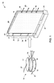
- FIG. 1 is a cross-sectional view of a thermal management system 10 including a wire frame 12.
- a synthetic jet 16 is mounted within a cavity 20 in a heat sink 24 including one or more respective fins 28.
- the synthetic jet 16 includes two piezo disks 15, 17 with an elastomeric wall 18 between them.
- the elastomeric wall is made of silicone material.
- the elastomeric wall 18 includes at least one orifice 19 for fluid flow. Electrical wires 21 attached to the piezo disk 17 ensure electrical connection to the synthetic jet 16.
- the synthetic jet 16 is inserted into the fin 28 via the wire frame 12.
- the wire frame or array of wires includes three wires 32, 34, 36 attached to the synthetic jet through holes (not shown) on the fin 28.
- Non-limiting example of material used in the wires 32, 34, and 36 are copper and aluminum.
- the fin is made of aluminum.
- the synthetic jet 16 also includes multiple orifices 19 through which a fluid 23 is ejected. In one embodiment, the fluid is air.
- a slot at a base center 37 of the fin 28 may be opened and a similar wire frame 12 may be employed therein. It will be appreciated that although one heat sink, one fin and synthetic jet is illustrated herein, there may be any number of heat sinks, fins and synthetic jets employed.
- FIG. 2 is a cross-sectional view of a thermal management system 40 including a gasket 42.
- the gasket 42 is disposed between an outer surface 44 of the piezo disk 17 ( FIG. 1 ) and an inner surface 27 of the fin 28.
- the outer surface 44 of the piezo disk 17 bellows in and out within the fin 28.
- a second gasket is adhesively coupled to the other piezo disk 15 ( FIG. 1 ).
- a couple of different manufacturing techniques may be employed for the mechanical coupling of the gasket 42 with the synthetic jet 16 inserted into the fin 28.
- the gasket 42 may be manufactured separately and an adhesive is applied on each side of the gasket.
- the gasket 42 is further attached to the jet 16 that is separately manufactured, with the adhesive on one side that would have enough tact at room temperature and the jet 16 is then inserted into the fin 28.
- heat or a chemical is applied to ensure desirable tact to the adhesive on the other side.
- the thickness of the gasket 42 may be selected based upon a desirable volume required for the piezo disk 17 to bellow back and forth. For example, if a desirable volume required for bellowing is 300 ⁇ m, the thickness of the gasket would be at least 300 ⁇ m to avoid collision of the jet 16 with the inner surface 27 of the fin 28.
- the gasket 42 is built onto the piezo disk 17 during the manufacturing of the synthetic jet 16 and an adhesive is further applied on an outer gasket material.
- the adhesive is activated either via mechanical pressure, heat, or chemical activation. Subsequently the adhesive bonds the gasket 42 to the inner suface 27 of the fin.
- the gasket is dispensed over the synthetic jet and after attachment to the fin, is cured at a specified temperature.
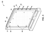
- FIG. 3 is a cross-sectional view of a thermal management system 60 including multiple bumps 62.
- the bumps 62 are formed at different locations 64 on an outer surface 44 of the piezo disk 17 ( FIG. 1 ) of the synthetic jet 16. Similar shaped dimples (not shown) are formed at the same locations on the inner side 27 of the fin 28 such that the bumps 62 align into respective dimples to provide desirable mechanical coupling of the synthetic jet 16 and the fin 28.
- dimples are formed by drilling holes on the inner side 27 of the fin 28 and later filling the holes with epoxy to establish smooth bumps over the surface.
- the bumps are formed by a stamping process via a dye. It will be appreciated that any number of dimples and bumps may be formed.
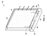
- FIG. 4 is a cross-sectional view of a thermal management system 80 including multiple locator pins 82, 84, 86 and 88.
- the locator pins are welded or soldered on an outer surface 44 of the piezo disk 17.
- two locator pins 82, 84 and 86, 88 are welded on each side of the piezo disk respectively.
- tight fitting holes 92 are drilled in the base/heat sink 24 ( FIG. 1 ) of the fin 28 to accept the locator pins.
- the locator pins ensure a tight mechanical coupling between the synthetic jet 16 and the fin 28. Again, any number of holes and locator pins may be employed.
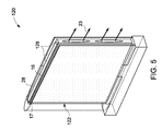
- FIG. 5 is a cross-sectional view of a thermal management system 120 including sheet 122 of non-conductive tape on a whole area of each surface 44 of the piezo disks 15, 17.
- the sheet 122 electrically separates the synthetic jet 16 from the fin 28 to avoid potential electric shorting of the jet 16 in contact with the metallic inner surface 27 of the fin 28.
- a non-limiting example of non-conductive tape is Kapton.
- a layer 128 of silicone is applied on a top opening 132 of the fin 28 to enclose synthetic jet 16 into the cavity of the fin 28. The layer 128 ensures secure coupling of the synthetic jet 16 with the fin 28.
- a smooth layer 128 also provides an aerodynamic surface for the air flow in the heatsink 24.
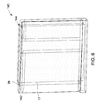
- FIG. 6 is a cross-sectional view of a thermal management system 140 including extruded synthetic jets 142.
- the extrusions 144 of the synthetic jet 142 enable top and bottom surfaces of the synthetic jet 142 to fit into external support slots that ensure a rigid attachment with the fin 28.
- the piezo disks 15, 17 are elongated above and below (if needed) the slot into which it is fitted.
- a silicone material (not shown) may be introduced in the extrusion slot to hold the synthetic jet 16.
- FIG. 7 is a top view of a thermal management system 180 including a fin cap 182.
- the fin cap 182 is disposed on a top opening 132 of the fin 28.
- the fin cap 182 is designed such that the synthetic jet 16 will be firmly enclosed within the fin 28, without being in contact with the cap.
- Through holes 186 may be formed in the fin cap 182 to facilitate a path for electrical connection of the synthetic jet 16.
- the shape of the fin cap 182 is similar to cross-section of the fin with a concave end. In another embodiment, the shape may be similar to cross-section of the fin with a short extruded wall fitting end.
- a single fin cap may be employed for each fin, or a top plate including a number of caps may cover all the fins.
- the fin cap 182 is adhesively coupled to the fin via a silicone or epoxy.
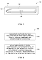
- FIG. 8 is a flow chart representing steps in an exemplary method 200 for manufacturing a thermal management system.
- the method 200 includes disposing at least one heat sink including one or more respective fins, wherein each of the fins includes one or more respective cavities in step 202.
- a synthetic jet stack including at least one synthetic jet is mounted in the fin in step 204, employing at least one engaging structure to provide rigid positioning of the synthetic jet stack within the fins.
- the synthetic jet includes at least one orifice through which a fluid is ejected.
- an engaging structure is employed by attaching an array of wires into each of the at least one synthetic jets to the respective one or more fins.
- the engaging structure is employed by adhesively coupling a gasket to an outer surface of the at least one synthetic jet and an inner surface of the fins.
- the engaging structure is employed by forming multiple bumps on an outer surface of the synthetic jet, and the multiple bumps are disposed upon multiple respective dimples embedded on the surface of the fins.
- the engaging structure is employed by disposing multiple locator pins on an outer surface of the synthetic jet, and the locator pins are fit into multiple respective holes drilled into the heat sink.
- the engaging structure is employed by adhering a sheet of non-conductive tape to each outer surface of the synthetic jets, and a layer of silicone is applied at a top opening side of the fins to enclose the synthetic jets into the cavities.
- the engaging structure is employed by forming extrusions in the synthetic jets, and the extrusions are fit into multiple external support slots on at least one of a top and a bottom surface of the fins, and a silicone adhesive is applied to the slots to ensure a rigid attachment.
- the engaging structure is employed by disposing a fin cap on a top opening of each of the respective fins such that the synthetic jets are rigidly disposed within the fins, wherein the fin cap includes one or more holes to facilitate electrical connection to the synthetic jets.
- the engaging structure is employed by disposing a top plate comprising multiple fin caps configured to cover each of the fins, such that the synthetic jets are rigidly disposed within the fins, the fin cap including one or more holes to facilitate electrical connection to the synthetic jets.
- thermal management system and method described above thus provide a way to achieve a convenient and efficient means of packaging synthetic jet embedded fins. This technique also provides energy efficient cooling of electronic devices. Further, such systems may be employed with low power fans in electronics to provide the desirable high performance cooling.
Landscapes
- Engineering & Computer Science (AREA)
- Microelectronics & Electronic Packaging (AREA)
- Physics & Mathematics (AREA)
- Thermal Sciences (AREA)
- Mechanical Engineering (AREA)
- Cooling Or The Like Of Electrical Apparatus (AREA)
- Cooling Or The Like Of Semiconductors Or Solid State Devices (AREA)
Applications Claiming Priority (1)
| Application Number | Priority Date | Filing Date | Title |
|---|---|---|---|
| US12/911,995 US9478479B2 (en) | 2010-10-26 | 2010-10-26 | Thermal management system and method |
Publications (2)
| Publication Number | Publication Date |
|---|---|
| EP2447992A2 true EP2447992A2 (de) | 2012-05-02 |
| EP2447992A3 EP2447992A3 (de) | 2013-01-16 |
Family
ID=45023568
Family Applications (1)
| Application Number | Title | Priority Date | Filing Date |
|---|---|---|---|
| EP11186013A Withdrawn EP2447992A3 (de) | 2010-10-26 | 2011-10-20 | System und Verfahren zur Wärmeverwaltung |
Country Status (5)
| Country | Link |
|---|---|
| US (2) | US9478479B2 (de) |
| EP (1) | EP2447992A3 (de) |
| CN (1) | CN102456645B (de) |
| BR (1) | BRPI1104371A2 (de) |
| CA (1) | CA2755589A1 (de) |
Cited By (4)
| Publication number | Priority date | Publication date | Assignee | Title |
|---|---|---|---|---|
| WO2014004056A1 (en) * | 2012-06-29 | 2014-01-03 | General Electric Company | Thermal management in optical and electronic devices |
| EP2698538A3 (de) * | 2012-08-15 | 2014-06-18 | General Electric Company | Multifunktioneller synthetischer Strahl und Verfahren zu seiner Herstellung |
| EP2866255A3 (de) * | 2013-10-28 | 2015-08-05 | General Electric Company | System und Verfahren für verbesserte Konvektionskühlung von temperaturabhängigen leistungserzeugenden und stromverbrauchenden Elektrovorrichtungen |
| WO2017099677A1 (en) * | 2015-12-09 | 2017-06-15 | Ozyegin Universitesi | Heat sink cooling with preferred synthetic jet cooling devices |
Families Citing this family (10)
| Publication number | Priority date | Publication date | Assignee | Title |
|---|---|---|---|---|
| US10274263B2 (en) | 2009-04-09 | 2019-04-30 | General Electric Company | Method and apparatus for improved cooling of a heat sink using a synthetic jet |
| CN104365187A (zh) * | 2012-05-03 | 2015-02-18 | 爱立信(中国)通信有限公司 | 用于冷却电信设备的方法和装置 |
| US20140268545A1 (en) * | 2013-02-22 | 2014-09-18 | Nuventix, Inc. | Modular synthetic jet ejector and systems incorporating the same |
| WO2014159881A1 (en) | 2013-03-14 | 2014-10-02 | General Electric Company | Low resonance acoustic synthetic jet structure |
| EP2969231B1 (de) | 2013-03-14 | 2019-10-23 | General Electric Company | Aufhängungsstruktur für synthetischen strahl |
| US9879661B2 (en) | 2014-08-29 | 2018-01-30 | General Electric Company | Vibrational fluid mover jet with active damping mechanism |
| US11222830B2 (en) * | 2018-01-03 | 2022-01-11 | Lenovo (Beijing) Co., Ltd. | Heat dissipation structure and electronic device |
| US11204204B2 (en) * | 2019-03-08 | 2021-12-21 | Toyota Motor Engineering & Manufacturing North America, Inc. | Acoustic absorber with integrated heat sink |
| US12414261B2 (en) * | 2021-06-25 | 2025-09-09 | Intel Corporation | Thermal management systems for electronic devices and related methods |
| CN115768077B (zh) * | 2022-12-01 | 2026-02-03 | 西安交通大学 | 一种射流散热装置 |
Family Cites Families (64)
| Publication number | Priority date | Publication date | Assignee | Title |
|---|---|---|---|---|
| US2766619A (en) | 1953-06-26 | 1956-10-16 | Tribus Myron | Ice detecting apparatus |
| DE2015694B2 (de) | 1970-04-02 | 1971-11-11 | Exatest Meßtechnik GmbH, 5090 Le verkusen | Verfahren zur beruehrungslosen messung der breite oder lage eines gegenstandes mittels eines sichtstrahls |
| US3692414A (en) | 1971-02-24 | 1972-09-19 | Harry L Hosterman | Non-contacting measuring probe |
| US4501319A (en) * | 1979-04-17 | 1985-02-26 | The United States Of America As Represented By The Secretary Of The Army | Piezoelectric polymer heat exchanger |
| US4498851A (en) * | 1980-05-02 | 1985-02-12 | Piezo Electric Products, Inc. | Solid state blower |
| DD218672A1 (de) | 1982-07-07 | 1985-02-13 | Ilmenau Tech Hochschule | Optisch-beruehrungslose mehrkordinaten-antasteinrichtung |
| US4583854A (en) | 1982-07-15 | 1986-04-22 | General Electric Company | High resolution electronic automatic imaging and inspecting system |
| US4745290A (en) | 1987-03-19 | 1988-05-17 | David Frankel | Method and apparatus for use in making custom shoes |
| US4736247A (en) | 1987-05-04 | 1988-04-05 | The United States Of America As Represented By The Administrator Of The National Aeronautics And Space Administration | Range and range rate system |
| JPH0164864U (de) * | 1987-10-21 | 1989-04-26 | ||
| US4966460A (en) | 1987-10-28 | 1990-10-30 | The Ingersoll Milling Machine Company | Laser gauging of rotary cutting tools |
| US4923000A (en) | 1989-03-03 | 1990-05-08 | Microelectronics And Computer Technology Corporation | Heat exchanger having piezoelectric fan means |
| US5369286A (en) | 1989-05-26 | 1994-11-29 | Ann F. Koo | Method and apparatus for measuring stress in a film applied to surface of a workpiece |
| DE9110287U1 (de) | 1991-08-20 | 1991-10-02 | Siemens AG, 8000 München | Einrichtung zur berührungslosen Messung der Kerndicke, des Durchmessers und des Rundlaufs von Microbohrern der Leiterplattentechnik |
| US5570186A (en) | 1992-04-28 | 1996-10-29 | Mtu Motoren- Und Turbinen-Union Munich Gmbh | Method for inspecting the curvature of a profile, such an edge of a turbine blade |
| US5760333A (en) * | 1992-08-06 | 1998-06-02 | Pfu Limited | Heat-generating element cooling device |
| US5445215A (en) | 1992-12-22 | 1995-08-29 | Herbert; Edward | Fan assembly with heat sink |
| US5477371A (en) | 1993-12-13 | 1995-12-19 | Shafir Production Systems Ltd. | Three-dimensional, non-contact scanning apparatus and method |
| US5568260A (en) | 1995-03-31 | 1996-10-22 | General Electric Company | Precision non-contact measurement system for curved workpieces |
| US5846081A (en) | 1995-08-23 | 1998-12-08 | Bushway; Geoffrey C. | Computerized instrument platform positioning system |
| JPH09139448A (ja) | 1995-11-13 | 1997-05-27 | Fujitsu Denso Ltd | 半導体の取付具及びその取付方法並びにこれを用いた半導体装置 |
| JP3159071B2 (ja) | 1996-08-01 | 2001-04-23 | 株式会社日立製作所 | 放熱フィンを有する電気装置 |
| US5781411A (en) | 1996-09-19 | 1998-07-14 | Gateway 2000, Inc. | Heat sink utilizing the chimney effect |
| JPH10141300A (ja) * | 1996-11-06 | 1998-05-26 | Honda Motor Co Ltd | 流体輸送装置 |
| US6016250A (en) | 1998-01-30 | 2000-01-18 | Credence Systems Corporation | Self-balancing thermal control device for integrated circuits |
| US6788807B1 (en) | 1998-02-13 | 2004-09-07 | Minolta Co., Ltd. | Three dimensional information measurement method and apparatus |
| US6185030B1 (en) | 1998-03-20 | 2001-02-06 | James W. Overbeck | Wide field of view and high speed scanning microscopy |
| JP2001075624A (ja) | 1999-07-01 | 2001-03-23 | Mori Seiki Co Ltd | Nc工作機械のツールパスデータ生成装置及びこれを備えた数値制御装置 |
| US6110306A (en) | 1999-11-18 | 2000-08-29 | The United States Of America As Represented By The Secretary Of The Navy | Complexed liquid fuel compositions |
| JP2001332671A (ja) | 2000-05-23 | 2001-11-30 | Nohira Seisakusho:Kk | ヒートシンク固定構造 |
| JP2002026214A (ja) | 2000-07-12 | 2002-01-25 | Sumitomo Metal Ind Ltd | 電子部品冷却装置 |
| US6296048B1 (en) * | 2000-09-08 | 2001-10-02 | Powerwave Technologies, Inc. | Heat sink assembly |
| US6666261B2 (en) * | 2001-06-15 | 2003-12-23 | Foxconn Precision Components Co., Ltd. | Liquid circulation cooler |
| DE10211070A1 (de) | 2002-03-13 | 2003-09-25 | Gurny Broesch Andrea | Vorrichtung zum Vermessen eines Messobjekts |
| US6588497B1 (en) * | 2002-04-19 | 2003-07-08 | Georgia Tech Research Corporation | System and method for thermal management by synthetic jet ejector channel cooling techniques |
| US6817405B2 (en) * | 2002-06-03 | 2004-11-16 | International Business Machines Corporation | Apparatus having forced fluid cooling and pin-fin heat sink |
| US20040263863A1 (en) | 2003-01-27 | 2004-12-30 | Rogers William E | System and method for design and manufacture of custom face masks |
| US7204615B2 (en) * | 2003-03-31 | 2007-04-17 | Lumination Llc | LED light with active cooling |
| US7027145B2 (en) | 2003-06-24 | 2006-04-11 | The Regents Of The University Of Michigan | Reconfigurable surface finish inspection apparatus for cylinder bores and other surfaces |
| CN1233038C (zh) | 2003-07-11 | 2005-12-21 | 北京工业大学 | 微射流阵列冷却热沉 |
| DE102004014153A1 (de) | 2004-03-23 | 2005-10-13 | IBTL - Ing. Büro Lang & Armlich GmbH | Koordinatenmessgerät mit Wechseloptik |
| US20060021736A1 (en) | 2004-07-29 | 2006-02-02 | International Rectifier Corporation | Pin type heat sink for channeling air flow |
| US7286347B2 (en) | 2004-08-10 | 2007-10-23 | Dupont Displays | Electronic device having a temperature control system |
| US7182124B2 (en) | 2004-08-31 | 2007-02-27 | Egbon Electronics Ltd. | Heat sink structure |
| US7252140B2 (en) | 2004-09-03 | 2007-08-07 | Nuveatix, Inc. | Apparatus and method for enhanced heat transfer |
| US7249625B2 (en) * | 2005-08-03 | 2007-07-31 | Cooler Master Co., Ltd. | Water-cooling heat dissipation device |
| US7607470B2 (en) * | 2005-11-14 | 2009-10-27 | Nuventix, Inc. | Synthetic jet heat pipe thermal management system |
| US7577491B2 (en) | 2005-11-30 | 2009-08-18 | General Electric Company | System and method for extracting parameters of a cutting tool |
| EP1797992A1 (de) | 2005-12-15 | 2007-06-20 | Ingersoll Machine Tools, Inc. | Bestimmung der Schneidewerkzeugdimensionen und des Rundlauffehlers unter Verwendung von akustischen Emissionen |
| WO2008048493A2 (en) | 2006-10-13 | 2008-04-24 | Nuventix, Inc. | Thermal management of very small form factor projectors with synthetic jets |
| US20080137289A1 (en) | 2006-12-08 | 2008-06-12 | General Electric Company | Thermal management system for embedded environment and method for making same |
| US7768655B2 (en) | 2006-12-20 | 2010-08-03 | General Electric Company | Methods and system for measuring an object |
| JP2008196989A (ja) | 2007-02-14 | 2008-08-28 | General Electric Co <Ge> | 切削工具のパラメータを抽出するためのシステム及び方法 |
| US20080310110A1 (en) | 2007-06-12 | 2008-12-18 | General Electric Company | System and method for mounting a cooling device and method of fabrication |
| US20090145581A1 (en) | 2007-12-11 | 2009-06-11 | Paul Hoffman | Non-linear fin heat sink |
| US7891410B1 (en) * | 2008-06-26 | 2011-02-22 | Lockheed Martin Corporation | Devices for heat exchange |
| US20090321046A1 (en) | 2008-06-30 | 2009-12-31 | Alcatel-Lucent Technologies Inc. | Flow diverters to enhance heat sink performance |
| US20100014251A1 (en) | 2008-07-15 | 2010-01-21 | Advanced Micro Devices, Inc. | Multidimensional Thermal Management Device for an Integrated Circuit Chip |
| US20100038056A1 (en) | 2008-08-15 | 2010-02-18 | Ellsworth Joseph R | High performance compact heat exchanger |
| US8453715B2 (en) | 2008-10-30 | 2013-06-04 | General Electric Company | Synthetic jet embedded heat sink |
| US8496049B2 (en) * | 2009-04-09 | 2013-07-30 | General Electric Company | Heat sinks with distributed and integrated jet cooling |
| US9615482B2 (en) * | 2009-12-11 | 2017-04-04 | General Electric Company | Shaped heat sinks to optimize flow |
| US8584735B2 (en) | 2009-07-28 | 2013-11-19 | Aerojet Rocketdyne Of De, Inc. | Cooling device and method with synthetic jet actuator |
| JP2011103395A (ja) | 2009-11-11 | 2011-05-26 | Sumitomo Electric Ind Ltd | 発熱部品の放熱構造及びこの放熱構造を有している回路装置 |
-
2010
- 2010-10-26 US US12/911,995 patent/US9478479B2/en active Active
-
2011
- 2011-10-20 EP EP11186013A patent/EP2447992A3/de not_active Withdrawn
- 2011-10-20 CA CA2755589A patent/CA2755589A1/en not_active Abandoned
- 2011-10-24 BR BRPI1104371-7A patent/BRPI1104371A2/pt not_active IP Right Cessation
- 2011-10-26 CN CN201110354647.0A patent/CN102456645B/zh active Active
-
2016
- 2016-10-20 US US15/298,677 patent/US20170040242A1/en not_active Abandoned
Non-Patent Citations (1)
| Title |
|---|
| None |
Cited By (9)
| Publication number | Priority date | Publication date | Assignee | Title |
|---|---|---|---|---|
| WO2014004056A1 (en) * | 2012-06-29 | 2014-01-03 | General Electric Company | Thermal management in optical and electronic devices |
| US9194575B2 (en) | 2012-06-29 | 2015-11-24 | General Electric Company | Thermal management in optical and electronic devices |
| EP2698538A3 (de) * | 2012-08-15 | 2014-06-18 | General Electric Company | Multifunktioneller synthetischer Strahl und Verfahren zu seiner Herstellung |
| US9215520B2 (en) | 2012-08-15 | 2015-12-15 | General Electric Company | Multi-function synthetic jet and method of manufacturing same |
| US10165343B2 (en) | 2012-08-15 | 2018-12-25 | General Electric Company | Multi-function synthetic jet and method of manufacturing same |
| EP2866255A3 (de) * | 2013-10-28 | 2015-08-05 | General Electric Company | System und Verfahren für verbesserte Konvektionskühlung von temperaturabhängigen leistungserzeugenden und stromverbrauchenden Elektrovorrichtungen |
| US9570643B2 (en) | 2013-10-28 | 2017-02-14 | General Electric Company | System and method for enhanced convection cooling of temperature-dependent power producing and power consuming electrical devices |
| WO2017099677A1 (en) * | 2015-12-09 | 2017-06-15 | Ozyegin Universitesi | Heat sink cooling with preferred synthetic jet cooling devices |
| US10629514B2 (en) | 2015-12-09 | 2020-04-21 | Ozyegin Universitesi | Heat sink cooling with preferred synthetic jet cooling devices |
Also Published As
| Publication number | Publication date |
|---|---|
| EP2447992A3 (de) | 2013-01-16 |
| CN102456645B (zh) | 2016-08-03 |
| CN102456645A (zh) | 2012-05-16 |
| CA2755589A1 (en) | 2012-04-26 |
| US20120097377A1 (en) | 2012-04-26 |
| BRPI1104371A2 (pt) | 2014-01-07 |
| US9478479B2 (en) | 2016-10-25 |
| US20170040242A1 (en) | 2017-02-09 |
Similar Documents
| Publication | Publication Date | Title |
|---|---|---|
| US9478479B2 (en) | Thermal management system and method | |
| US8885343B2 (en) | Heat dissipation from a control unit | |
| KR100665933B1 (ko) | 파워 세미컨덕터 모듈 | |
| KR200448519Y1 (ko) | 돌출형 ⅰc 패키지용 방열판 | |
| JP2009105394A (ja) | 内部冷却構造を有する回路基板を利用した電気アセンブリ | |
| US9974158B2 (en) | Air-cavity package with two heat dissipation interfaces | |
| EP3695438B1 (de) | Wärmesenke, chip mit integrierter schaltung und leiterplatte | |
| CN106098638A (zh) | 包括流体冷却通道的电子模块及其制造方法 | |
| US20180218955A1 (en) | Air-cavity package with enhanced package integration level and thermal performance | |
| KR20050077866A (ko) | 열방출형 반도체 패키지 및 그 제조방법 | |
| US20170287798A1 (en) | Baseplate for an electronic module and method of manufacturing the same | |
| CN105659400A (zh) | 电路和用于制造电路的方法 | |
| JP2016201186A (ja) | 電池モジュール | |
| JP4284636B2 (ja) | 金属基板 | |
| EP2548224B1 (de) | Kühlanordnung zur kühlung einer wärmeerzeugungskomponente | |
| CN101689538B (zh) | 制造固定功率模块的方法 | |
| US20040227230A1 (en) | Heat spreaders | |
| US10629354B2 (en) | Inductive component | |
| CN1983575A (zh) | 柔性芯片散热器和利用该散热器进行冷却的方法和系统 | |
| JPH0278255A (ja) | 樹脂封止型半導体装置 | |
| EP3214646A1 (de) | Wärmeableitende struktur | |
| JP5860665B2 (ja) | 熱管理システム及び方法 | |
| CN218526489U (zh) | 一种高散热芯片板体结构 | |
| US20240244754A1 (en) | Circuit Device | |
| JP2009253206A (ja) | 樹脂封止型半導体装置およびその実装構造 |
Legal Events
| Date | Code | Title | Description |
|---|---|---|---|
| PUAI | Public reference made under article 153(3) epc to a published international application that has entered the european phase |
Free format text: ORIGINAL CODE: 0009012 |
|
| AK | Designated contracting states |
Kind code of ref document: A2 Designated state(s): AL AT BE BG CH CY CZ DE DK EE ES FI FR GB GR HR HU IE IS IT LI LT LU LV MC MK MT NL NO PL PT RO RS SE SI SK SM TR |
|
| AX | Request for extension of the european patent |
Extension state: BA ME |
|
| PUAL | Search report despatched |
Free format text: ORIGINAL CODE: 0009013 |
|
| AK | Designated contracting states |
Kind code of ref document: A3 Designated state(s): AL AT BE BG CH CY CZ DE DK EE ES FI FR GB GR HR HU IE IS IT LI LT LU LV MC MK MT NL NO PL PT RO RS SE SI SK SM TR |
|
| AX | Request for extension of the european patent |
Extension state: BA ME |
|
| RIC1 | Information provided on ipc code assigned before grant |
Ipc: H01L 23/467 20060101AFI20121212BHEP Ipc: H05K 7/20 20060101ALI20121212BHEP |
|
| 17P | Request for examination filed |
Effective date: 20130716 |
|
| RBV | Designated contracting states (corrected) |
Designated state(s): AL AT BE BG CH CY CZ DE DK EE ES FI FR GB GR HR HU IE IS IT LI LT LU LV MC MK MT NL NO PL PT RO RS SE SI SK SM TR |
|
| 17Q | First examination report despatched |
Effective date: 20150805 |
|
| GRAP | Despatch of communication of intention to grant a patent |
Free format text: ORIGINAL CODE: EPIDOSNIGR1 |
|
| INTG | Intention to grant announced |
Effective date: 20180905 |
|
| STAA | Information on the status of an ep patent application or granted ep patent |
Free format text: STATUS: THE APPLICATION IS DEEMED TO BE WITHDRAWN |
|
| 18D | Application deemed to be withdrawn |
Effective date: 20190116 |