EP2447566A2 - Schwingungsdämpfer mit amplitudenselektiver Dämpfkraft - Google Patents
Schwingungsdämpfer mit amplitudenselektiver Dämpfkraft Download PDFInfo
- Publication number
- EP2447566A2 EP2447566A2 EP11182840A EP11182840A EP2447566A2 EP 2447566 A2 EP2447566 A2 EP 2447566A2 EP 11182840 A EP11182840 A EP 11182840A EP 11182840 A EP11182840 A EP 11182840A EP 2447566 A2 EP2447566 A2 EP 2447566A2
- Authority
- EP
- European Patent Office
- Prior art keywords
- piston
- piston rod
- rod
- vibration damper
- spring plate
- Prior art date
- Legal status (The legal status is an assumption and is not a legal conclusion. Google has not performed a legal analysis and makes no representation as to the accuracy of the status listed.)
- Withdrawn
Links
- 238000013016 damping Methods 0.000 title claims abstract description 17
- 239000007787 solid Substances 0.000 description 2
- 241000209035 Ilex Species 0.000 description 1
- 238000006073 displacement reaction Methods 0.000 description 1
- 230000000694 effects Effects 0.000 description 1
- 230000002093 peripheral effect Effects 0.000 description 1
Images

Classifications
-
- F—MECHANICAL ENGINEERING; LIGHTING; HEATING; WEAPONS; BLASTING
- F16—ENGINEERING ELEMENTS AND UNITS; GENERAL MEASURES FOR PRODUCING AND MAINTAINING EFFECTIVE FUNCTIONING OF MACHINES OR INSTALLATIONS; THERMAL INSULATION IN GENERAL
- F16F—SPRINGS; SHOCK-ABSORBERS; MEANS FOR DAMPING VIBRATION
- F16F9/00—Springs, vibration-dampers, shock-absorbers, or similarly-constructed movement-dampers using a fluid or the equivalent as damping medium
- F16F9/32—Details
- F16F9/44—Means on or in the damper for manual or non-automatic adjustment; such means combined with temperature correction
- F16F9/46—Means on or in the damper for manual or non-automatic adjustment; such means combined with temperature correction allowing control from a distance, i.e. location of means for control input being remote from site of valves, e.g. on damper external wall
- F16F9/464—Control of valve bias or pre-stress, e.g. electromagnetically
-
- F—MECHANICAL ENGINEERING; LIGHTING; HEATING; WEAPONS; BLASTING
- F16—ENGINEERING ELEMENTS AND UNITS; GENERAL MEASURES FOR PRODUCING AND MAINTAINING EFFECTIVE FUNCTIONING OF MACHINES OR INSTALLATIONS; THERMAL INSULATION IN GENERAL
- F16F—SPRINGS; SHOCK-ABSORBERS; MEANS FOR DAMPING VIBRATION
- F16F9/00—Springs, vibration-dampers, shock-absorbers, or similarly-constructed movement-dampers using a fluid or the equivalent as damping medium
- F16F9/32—Details
- F16F9/34—Special valve constructions; Shape or construction of throttling passages
-
- F—MECHANICAL ENGINEERING; LIGHTING; HEATING; WEAPONS; BLASTING
- F16—ENGINEERING ELEMENTS AND UNITS; GENERAL MEASURES FOR PRODUCING AND MAINTAINING EFFECTIVE FUNCTIONING OF MACHINES OR INSTALLATIONS; THERMAL INSULATION IN GENERAL
- F16F—SPRINGS; SHOCK-ABSORBERS; MEANS FOR DAMPING VIBRATION
- F16F9/00—Springs, vibration-dampers, shock-absorbers, or similarly-constructed movement-dampers using a fluid or the equivalent as damping medium
- F16F9/32—Details
-
- F—MECHANICAL ENGINEERING; LIGHTING; HEATING; WEAPONS; BLASTING
- F16—ENGINEERING ELEMENTS AND UNITS; GENERAL MEASURES FOR PRODUCING AND MAINTAINING EFFECTIVE FUNCTIONING OF MACHINES OR INSTALLATIONS; THERMAL INSULATION IN GENERAL
- F16F—SPRINGS; SHOCK-ABSORBERS; MEANS FOR DAMPING VIBRATION
- F16F9/00—Springs, vibration-dampers, shock-absorbers, or similarly-constructed movement-dampers using a fluid or the equivalent as damping medium
- F16F9/32—Details
- F16F9/50—Special means providing automatic damping adjustment, i.e. self-adjustment of damping by particular sliding movements of a valve element, other than flexions or displacement of valve discs; Special means providing self-adjustment of spring characteristics
- F16F9/512—Means responsive to load action, i.e. static load on the damper or dynamic fluid pressure changes in the damper, e.g. due to changes in velocity
- F16F9/5126—Piston, or piston-like valve elements
Definitions
- the invention relates to a vibration damper with amplitude-selective damping force according to the preamble of patent claim 1.
- the generic DE 100 41 199 C1 relates to a vibration damper, on the piston rod, a first piston is attached.
- the piston has damping valves for both directions of movement of the piston rod.
- the vibration damper has a second piston, which is designed to be displaceable relative to the force of at least one return spring relative to the piston rod.
- this piston has damping valves for both directions of movement of the piston rod.
- Such a vibration damper leads in comparison to a conventional vibration damper with only a solid piston to a much more comfortable ride.
- this emphasized comfort-oriented attitude is considered disadvantageous, since the vehicle is no longer so directly responsive to rapid changes in direction of travel.
- a similar effect occurs when such a vibration damper is used in a spring-loaded cab.
- the object of the present invention is to solve the problem known from the prior art in a generic vibration damper.
- the object is achieved in that the spring plate is designed to be axially adjustable by means of an actuator.
- the bias of the return spring is varied, which in turn the point of use of the axially movable second piston can be fixed.
- the actuating device has an actuating rod, which is in operative connection with the spring plate.
- the actuating rod can be controlled manually, electrically, pneumatically or hydraulically.
- the piston rod is hollow and within the hollow piston rod, the actuating rod is arranged.
- the piston rod has a longitudinal slot in which a transverse pin is guided axially movable, which cooperates with the spring plate, wherein the actuating rod engages the cross bolt.
- the actuating rod is formed by a sleeve which is guided on the piston rod.
- the actuating rod executes a rotational movement and this rotational movement is converted by means of a thread in an axial movement of the spring plate.
- FIG. 1 shows a section of a vibration damper 1 of any design.
- a piston rod 5 is mounted axially displaceable on which a first piston 7 is fixed.
- the piston has damping valves 9; 11 for both directions of movement of the piston rod fifth
- a second piston 13 On a lateral surface of the piston rod 5, a second piston 13 is guided displaceably.
- the piston 13 also has damping valves 15; 17 for two directions of movement of the piston rod 5, wherein the concrete structure of the damping valves 15; 17 is subordinate to the present invention.
- the second piston 13 is held on both sides by at least one return spring 19 - 25 in a defined starting position on the piston rod 5. With their end facing away from the piston, the return springs 19 - 25 are supported on a spring plate 27; 29 off. In this embodiment, two return springs are used on each side of the piston.
- the spring plate 27 is axially adjustable via an actuator 31.
- the piston rod 5 is hollow in this embodiment and within the hollow piston rod 5, an actuating rod 33 is arranged, which is in operative connection with the spring plate 27.
- the piston rod 5 has a longitudinal slot 35, in which a transverse pin 37 is guided axially movable, which cooperates with the spring plate 27, wherein the actuating rod 33 engages the transverse pin 37.
- the actuating rod 33 may be controlled manually or by external energy axially.
- the cross pin 37 can not move laterally out of the slot, a locking washer 39 is used, which is simply threaded onto the piston rod 5.
- a peripheral edge of the lock washer is in axial overlap with the two end faces of the transverse pin 37th
- the actuating rod 33 is formed by a sleeve which is guided on the piston rod 5.
- the piston rod 5 can then be provided as a solid component.
- the actuating rod 33 then protrudes beyond an unillustrated end of the cylinder.
- the actuating rod 33 performs a rotational movement and this rotational movement by means of a thread 41 in an axial movement the spring plate 27 is implemented.
- the actuating rod 33 is no longer in the rest position of the force of the return springs 19 - 25 exposed.
- the rotational movement of the sleeve 33 is transmitted to the spring plate 27 via any positive connection 43.
- the thread 41 between the spring plate 27 and the piston rod 5 is executed. It is also possible to provide the thread 41 between the piston rod 5 and the sleeve 33.
Landscapes
- Engineering & Computer Science (AREA)
- General Engineering & Computer Science (AREA)
- Mechanical Engineering (AREA)
- Physics & Mathematics (AREA)
- Electromagnetism (AREA)
- Fluid Mechanics (AREA)
- Fluid-Damping Devices (AREA)
Abstract
Schwingungsdämpfer (1), umfassend einen Zylinder (3), in dem eine Kolbenstange (5) axial verschiebbar gelagert ist, wobei an der Kolbenstange (5) ein erster Kolben (7) mit Dämpfventilen (9;11) fixiert ist, mit einem zweiten Kolben (13), der Dämpfventile (15;17) aufweist, wobei der zweite Kolben (13) gegen mindestens eine Rückstellfeder (19-25) eine axiale Relativbewegung zur Kolbenstange (5) ausführen kann, wobei sich die mindestens eine Rückstellfeder (19-25) mit ihrem dem zweiten Kolben (13) abgewandten Ende an einem Federteller (27;29) abstützt, der mittels einer Betätigungseinrichtung (31) axial verstellbar ausgeführt ist.
Description
- Die Erfindung betrifft einen Schwingungsdämpfer mit amplitudenselektiver Dämpfkraft gemäß dem Oberbegriff von Patentanspruch 1.
- Die gattungsbildende
DE 100 41 199 C1 betrifft einen Schwingungsdämpfer, an dessen Kolbenstange ein erster Kolben befestigt ist. Der Kolben verfügt über Dämpfventile für beide Bewegungsrichtungen der Kolbenstange. Des Weiteren verfügt der Schwingungsdämpfer über einen zweiten Kolben, der gegen die Kraft von mindestens einer Rückstellfeder relativ zur Kolbenstange verschiebbar ausgeführt ist. Auch dieser Kolben weist Dämpfventile für beide Bewegungsrichtungen der Kolbenstange auf. - Bei kleinen Hubbewegungen üben nur die Dämpfventile des fest mit der Kolbenstange verbundenen ersten Kolbens eine Dämpfkraft auf. Wenn die Hubbewegung so groß ist, dass der zweite Kolben die Rückstellfeder so weit vorgespannt hat, dass bei einer weiteren Kolbenstangenbewegung eine ortsfeste Betriebsstellung des zweiten Kolbens zur Kolbenstange vorliegt, dann überlagern sich die Dämpfkräfte der Dämpfventile der beiden Kolben.
- Ein derartiger Schwingungsdämpfer führt im Vergleich zu einem konventionellen Schwingungsdämpfer mit nur einem festen Kolben zu einem deutlich komfortableren Fahrverhalten. Insbesondere bei sportlicheren Fahrzeugen wird jedoch diese betont komfortorientierte Einstellung als nachteilig angesehen, da das Fahrzeug bei schnellen Fahrtrichtungsänderungen nicht mehr so direkt reagiert. Ein ähnlicher Effekt tritt auf, wenn ein derartiger Schwingungsdämpfer bei einer federnd gelagerten Fahrerkabine verwendet wird.
- Die Aufgabe der vorliegenden Erfindung besteht darin, das aus dem Stand der Technik bekannte Problem bei einem gattungsbildenden Schwingungsdämpfer zu lösen.
- Erfindungsgemäß wird die Aufgabe dadurch gelöst, dass der Federteller mittels einer Betätigungseinrichtung axial verstellbar ausgeführt ist.
- Durch die Axialverschiebung des Federtellers wird die Vorspannung der Rückstellfeder variiert, wodurch wiederum der Einsatzpunkt des axial beweglichen zweiten Kolbens festlegbar ist.
- Gemäß einem vorteilhaften Unteranspruch weist die Betätigungseinrichtung eine Betätigungsstange auf, die mit dem Federteller in Wirkverbindung steht. Die Betätigungsstange kann manuell, elektrisch, pneumatisch oder auch hydraulisch angesteuert werden.
- Bei einer ersten Ausführungsform ist die Kolbenstange hohl ausgeführt und innerhalb der hohlen Kolbenstange ist die Betätigungsstange angeordnet.
- Dabei weist die Kolbenstange einen Längsschlitz auf, in dem ein Querbolzen axial beweglich geführt ist, der mit dem Federteller zusammenwirkt, wobei die Betätigungsstange am Querbolzen angreift.
- Alternativ wird die Betätigungsstange von einer Hülse gebildet, die auf der Kolbenstange geführt ist.
- Man kann vorsehen, dass die Betätigungsstange eine Drehbewegung ausführt und diese Drehbewegung mittels eines Gewindes in eine Axialbewegung des Federtellers umgesetzt wird.
- Anhand der folgenden Figurenbeschreibung soll die Erfindung näher erläutert werden.
- Es zeigt:
- Fig. 1
- Ausführungsform der Erfindung mit einer hohlen Kolbenstange
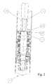
- Fig. 2
- Alternativvariante mit einer Hülse als Betätigungsstange
- Die
Figur 1 zeigt einen Ausschnitt aus einem Schwingungsdämpfer 1 beliebiger Bauform. In einem Zylinder 3 ist eine Kolbenstange 5 axial verschiebbar gelagert, an der ein erster Kolben 7 fixiert ist. Der Kolben verfügt Dämpfventile 9; 11 für beide Bewegungsrichtungen der Kolbenstange 5. - Auf einer Mantelfläche der Kolbenstange 5 ist ein zweiter Kolben 13 verschiebbar geführt. Der Kolben 13 verfügt ebenfalls über Dämpfventile 15; 17 für zwei Bewegungsrichtungen der Kolbenstange 5, wobei der konkrete Aufbau der Dämpfventile 15; 17 für die vorliegende Erfindung untergeordnet ist.
- Der zweite Kolben 13 wird beidseitig von mindestens einer Rückstellfeder 19 - 25 in einer definierten Ausgangsposition auf der Kolbenstange 5 gehalten. Mit ihren dem Kolben abgewandten Ende stützen sich die Rückstellfedern 19 - 25 an einem Federteller 27; 29 ab. In diesem Ausführungsbeispiel kommen zwei Rückstellfedern an jeder Kolbenseite zur Anwendung.
- Der Federteller 27 ist über eine Betätigungseinrichtung 31 axial verstellbar ausgeführt. Dafür ist die Kolbenstange 5 in diesem Ausführungsbeispiel hohl ausgeführt und innerhalb der hohlen Kolbenstange 5 ist eine Betätigungsstange 33 angeordnet ist, die mit dem Federteller 27 in Wirkverbindung steht. Die Kolbenstange 5 weist einen Längsschlitz 35 auf, in dem ein Querbolzen 37 axial beweglich geführt ist, der mit dem Federteller 27 zusammenwirkt, wobei die Betätigungsstange 33 am Querbolzen 37 angreift. Die Betätigungsstange 33 kann manuell oder durch Fremdenergie axial angesteuert sein. Damit sich der Querbolzen 37 seitlich nicht aus dem Schlitz bewegen kann, kommt eine Sicherungsscheibe 39 zur Anwendung, die einfach auf die Kolbenstange 5 aufgefädelt wird. Ein umlaufender Rand der Sicherungsscheibe steht in axialer Überdeckung mit den beiden Stirnseiten des Querbolzens 37.
- Zur Verstellung des Federtellers 27 wird auf die Betätigungsstange 33 eine Axialkraft ausgeübt. Dabei kann sich der Querbolzen 37 in dem Längsschlitz 35 der Kolbenstange 5 verschieben. Synchron wird dabei auch der Federteller 27 verschoben, wodurch sich die Vorspannung der Rückstellfedern 19 - 25 und damit auch der Einsatzpunkt des axial beweglichen Kolbens 13 verändert.
- Bei einer Alternativvariante wird die Betätigungsstange 33 von einer Hülse gebildet, die auf der Kolbenstange 5 geführt ist. Die Kolbenstange 5 kann dann als massives Bauteil vorgesehen sein. Die Betätigungsstange 33 ragt dann über ein nicht dargestelltes Ende des Zylinders heraus. Eine ebenfalls nicht dargestellte Kolbenstangendichtung gleitet dann auf der Betätigungsstange.
- Man kann auch vorsehen, dass die Betätigungsstange 33 eine Drehbewegung ausführt und diese Drehbewegung mittels eines Gewindes 41 in eine Axialbewegung des Federtellers 27 umgesetzt wird. Die Betätigungsstange 33 ist in der Ruheposition nicht mehr der Kraft der Rückstellfedern 19 - 25 ausgesetzt. Die Drehbewegung der Hülse 33 wird über eine beliebige Formschlussverbindung 43 auf den Federteller 27 übertragen. In diesem Fall ist das Gewinde 41 zwischen Federteller 27 und der Kolbenstange 5 ausgeführt. Man kann das Gewinde 41 auch zwischen der Kolbenstange 5 und der Hülse 33 vorsehen.
-
- 1
- Schwingungsdämpfer
- 3
- Zylinder
- 5
- Kolbenstange
- 7
- Kolben
- 9, 11
- Dämpfventile
- 13
- zweiter Kolben
- 15, 17
- Dämpfventile
- 19 - 25
- Rückstellfeder
- 27, 29
- Federteller
- 31
- Betätigungseinrichtung
- 33
- Betätigungsstange
- 35
- Längsschlitz
- 37
- Querbolzen
- 39
- Sicherungsscheibe
- 41
- Gewinde
- 43
- Formschlussverbindung
Claims (6)
- Schwingungsdämpfer (1), umfassend einen Zylinder (3), in dem eine Kolbenstange (5) axial verschiebbar gelagert ist, wobei an der Kolbenstange (5) ein erster Kolben (7) mit Dämpfventilen (9; 11) fixiert ist, mit einem zweiten Kolben (13), der Dämpfventile (15; 17) aufweist, wobei der zweite Kolben (13) gegen mindestens eine Rückstellfeder (19 - 25) eine axiale Relativbewegung zur Kolbenstange (5) ausführen kann, wobei sich die mindestens eine Rückstellfeder (19 - 25) mit ihrem dem zweiten Kolben (13) abgewandten Ende an einem Federteller (27; 29) abstützt,
dadurch gekennzeichnet,
dass der Federteller (27) mittels einer Betätigungseinrichtung (31) axial verstellbar ausgeführt ist. - Schwingungsdämpfer nach Anspruch 1,
dadurch gekennzeichnet,
dass die Betätigungseinrichtung (31) eine Betätigungsstange (33) aufweist, die mit dem Federteller (27) in Wirkverbindung steht. - Schwingungsdämpfer nach Anspruch 1,
dadurch gekennzeichnet,
dass die Kolbenstange (5) hohl ausgeführt ist und innerhalb der hohlen Kolbenstange (5) die Betätigungsstange (33) angeordnet ist. - Schwingungsdämpfer nach Anspruch 2,
dadurch gekennzeichnet,
dass die Kolbenstange (5) einen Längsschlitz (35) aufweist, in dem ein Querbolzen (37) axial beweglich geführt ist, der mit dem Federteller (27) zusammenwirkt, wobei die Betätigungsstange (33) am Querbolzen (37) angreift. - Schwingungsdämpfer nach Anspruch 2,
dadurch gekennzeichnet,
dass die Betätigungsstange (33) von einer Hülse gebildet wird, die auf der Kolbenstange (5) geführt ist. - Schwingungsdämpfer nach Anspruch 5,
dadurch gekennzeichnet,
dass die Betätigungsstange (33) eine Drehbewegung ausführt und diese Drehbewegung mittels eines Gewindes (41) in eine Axialbewegung des Federtellers (27) umgesetzt wird.
Applications Claiming Priority (1)
| Application Number | Priority Date | Filing Date | Title |
|---|---|---|---|
| DE102010049828A DE102010049828B4 (de) | 2010-10-27 | 2010-10-27 | Schwingungsdämpfer mit amplitudenselektiver Dämpfkraft |
Publications (1)
| Publication Number | Publication Date |
|---|---|
| EP2447566A2 true EP2447566A2 (de) | 2012-05-02 |
Family
ID=44720697
Family Applications (1)
| Application Number | Title | Priority Date | Filing Date |
|---|---|---|---|
| EP11182840A Withdrawn EP2447566A2 (de) | 2010-10-27 | 2011-09-27 | Schwingungsdämpfer mit amplitudenselektiver Dämpfkraft |
Country Status (3)
| Country | Link |
|---|---|
| EP (1) | EP2447566A2 (de) |
| KR (1) | KR20120044257A (de) |
| DE (1) | DE102010049828B4 (de) |
Cited By (1)
| Publication number | Priority date | Publication date | Assignee | Title |
|---|---|---|---|---|
| CN104986077A (zh) * | 2015-06-29 | 2015-10-21 | 苏州中航中振汽车饰件有限公司 | 体重区分式汽车座椅悬架 |
Citations (1)
| Publication number | Priority date | Publication date | Assignee | Title |
|---|---|---|---|---|
| DE10041199C1 (de) | 2000-08-23 | 2001-11-29 | Mannesmann Sachs Ag | Schwingungsdämpfer |
Family Cites Families (3)
| Publication number | Priority date | Publication date | Assignee | Title |
|---|---|---|---|---|
| DE2325247A1 (de) * | 1973-05-18 | 1974-12-05 | Daimler Benz Ag | Schwingungsdaempfer fuer fahrzeugabfederungen mit einer lastabhaengig arbeitenden hydraulischen daempfungsvorrichtung |
| DE19808698A1 (de) * | 1998-03-11 | 1999-09-16 | Schreiber Jens Uwe | Stoßdämpfer, der in der Druck- und Zugstufe separat regelbar ist |
| DE10237644B4 (de) * | 2002-08-13 | 2006-01-19 | Zf Sachs Ag | Federträger mit einem höhenverstellbaren Federteller |
-
2010
- 2010-10-27 DE DE102010049828A patent/DE102010049828B4/de not_active Expired - Fee Related
-
2011
- 2011-09-27 EP EP11182840A patent/EP2447566A2/de not_active Withdrawn
- 2011-10-26 KR KR1020110109637A patent/KR20120044257A/ko not_active Withdrawn
Patent Citations (1)
| Publication number | Priority date | Publication date | Assignee | Title |
|---|---|---|---|---|
| DE10041199C1 (de) | 2000-08-23 | 2001-11-29 | Mannesmann Sachs Ag | Schwingungsdämpfer |
Cited By (1)
| Publication number | Priority date | Publication date | Assignee | Title |
|---|---|---|---|---|
| CN104986077A (zh) * | 2015-06-29 | 2015-10-21 | 苏州中航中振汽车饰件有限公司 | 体重区分式汽车座椅悬架 |
Also Published As
| Publication number | Publication date |
|---|---|
| KR20120044257A (ko) | 2012-05-07 |
| DE102010049828B4 (de) | 2012-05-31 |
| DE102010049828A1 (de) | 2012-05-03 |
Similar Documents
| Publication | Publication Date | Title |
|---|---|---|
| EP2550168B1 (de) | Luftfederanordnung mit integriertem steuerventil | |
| AT519184B1 (de) | Längenverstellbares Pleuel mit Anschlagflächen | |
| DE102008035021B4 (de) | Greif- oder Spanneinheit | |
| DE102008063752B4 (de) | Kolbenstangenanbindung | |
| EP2998072B1 (de) | Federbeinspanner zum austausch einer feder oder eines stossdämpfers eines federbeins eines kraftfahrzeuges | |
| DE102008048507A1 (de) | Vorrichtung mit einstellbarer Spielfreiheit für ein Ansteuergerät | |
| EP1215412B1 (de) | Kolben-Zylinderaggregat mit einer Verstelleinrichtung | |
| EP2404066B1 (de) | Schwenkeinheit und anschlagmodul für eine schwenkeinheit | |
| DE102009049920A1 (de) | Spannvorrichtung | |
| EP3102445B1 (de) | Luftfederanordnung mit integriertem steuerventil und wippenförmigem betätigungsmittel | |
| DE102010049828B4 (de) | Schwingungsdämpfer mit amplitudenselektiver Dämpfkraft | |
| EP2602061B1 (de) | Betätigungsvorrichtung | |
| DE10062988B4 (de) | Hydraulische Betätigungseinrichtung an Kraftfahrzeugen | |
| DE102009013152A1 (de) | Dämpfungssystem zur Anschlagdämpfung | |
| DE102015112801A1 (de) | Gebereinheit | |
| DE102015119731A1 (de) | Dämpfervorrichtung | |
| DE102019118672B3 (de) | Greif- oder Spanneinheit mit Getriebeanordnung zur Aufrechterhaltung einer Greifkraft | |
| DE102017107673A1 (de) | Pleuel für eine variable Verdichtung einer Brennkraftmaschine | |
| DE102013002495B4 (de) | Kaltschmiedevorrichtung | |
| DE102008043247B3 (de) | Hypozykloidische Ausrückeinrichtung für eine Kraftfahrzeugkupplung | |
| WO2017207671A1 (de) | Längenverstellbare pleuelstange, vorrichtung zum einstellen eines verdichtungsverhältnisses und brennkraftmaschine | |
| DE102011081900A1 (de) | Haltevorrichtung für Kolbenstange | |
| WO2005064200A1 (de) | Mechanische spannvorrichtung für zugmittel mit gerichteter reibdämpfung | |
| DE112015004705T5 (de) | Stoßdämpfer | |
| EP1749790A2 (de) | System zur Verstellung eines Kranauslegers |
Legal Events
| Date | Code | Title | Description |
|---|---|---|---|
| PUAI | Public reference made under article 153(3) epc to a published international application that has entered the european phase |
Free format text: ORIGINAL CODE: 0009012 |
|
| AK | Designated contracting states |
Kind code of ref document: A2 Designated state(s): AL AT BE BG CH CY CZ DE DK EE ES FI FR GB GR HR HU IE IS IT LI LT LU LV MC MK MT NL NO PL PT RO RS SE SI SK SM TR |
|
| AX | Request for extension of the european patent |
Extension state: BA ME |
|
| STAA | Information on the status of an ep patent application or granted ep patent |
Free format text: STATUS: THE APPLICATION IS DEEMED TO BE WITHDRAWN |
|
| 18D | Application deemed to be withdrawn |
Effective date: 20160401 |