EP3102445B1 - Luftfederanordnung mit integriertem steuerventil und wippenförmigem betätigungsmittel - Google Patents
Luftfederanordnung mit integriertem steuerventil und wippenförmigem betätigungsmittel Download PDFInfo
- Publication number
- EP3102445B1 EP3102445B1 EP15702462.1A EP15702462A EP3102445B1 EP 3102445 B1 EP3102445 B1 EP 3102445B1 EP 15702462 A EP15702462 A EP 15702462A EP 3102445 B1 EP3102445 B1 EP 3102445B1
- Authority
- EP
- European Patent Office
- Prior art keywords
- air spring
- valve
- spring arrangement
- arrangement according
- actuating
- Prior art date
- Legal status (The legal status is an assumption and is not a legal conclusion. Google has not performed a legal analysis and makes no representation as to the accuracy of the status listed.)
- Active
Links
Images

Classifications
-
- B—PERFORMING OPERATIONS; TRANSPORTING
- B60—VEHICLES IN GENERAL
- B60G—VEHICLE SUSPENSION ARRANGEMENTS
- B60G15/00—Resilient suspensions characterised by arrangement, location or type of combined spring and vibration damper, e.g. telescopic type
- B60G15/08—Resilient suspensions characterised by arrangement, location or type of combined spring and vibration damper, e.g. telescopic type having fluid spring
- B60G15/12—Resilient suspensions characterised by arrangement, location or type of combined spring and vibration damper, e.g. telescopic type having fluid spring and fluid damper
-
- B—PERFORMING OPERATIONS; TRANSPORTING
- B60—VEHICLES IN GENERAL
- B60G—VEHICLE SUSPENSION ARRANGEMENTS
- B60G17/00—Resilient suspensions having means for adjusting the spring or vibration-damper characteristics, for regulating the distance between a supporting surface and a sprung part of vehicle or for locking suspension during use to meet varying vehicular or surface conditions, e.g. due to speed or load
- B60G17/02—Spring characteristics, e.g. mechanical springs and mechanical adjusting means
- B60G17/04—Spring characteristics, e.g. mechanical springs and mechanical adjusting means fluid spring characteristics
- B60G17/048—Spring characteristics, e.g. mechanical springs and mechanical adjusting means fluid spring characteristics with the regulating means inside the fluid springs
- B60G17/0485—Spring characteristics, e.g. mechanical springs and mechanical adjusting means fluid spring characteristics with the regulating means inside the fluid springs the springs being pneumatic springs with a flexible wall, e.g. with levelling valves
-
- B—PERFORMING OPERATIONS; TRANSPORTING
- B60—VEHICLES IN GENERAL
- B60G—VEHICLE SUSPENSION ARRANGEMENTS
- B60G17/00—Resilient suspensions having means for adjusting the spring or vibration-damper characteristics, for regulating the distance between a supporting surface and a sprung part of vehicle or for locking suspension during use to meet varying vehicular or surface conditions, e.g. due to speed or load
- B60G17/02—Spring characteristics, e.g. mechanical springs and mechanical adjusting means
- B60G17/04—Spring characteristics, e.g. mechanical springs and mechanical adjusting means fluid spring characteristics
- B60G17/052—Pneumatic spring characteristics
- B60G17/0523—Regulating distributors or valves for pneumatic springs
- B60G17/0525—Height adjusting or levelling valves
-
- B—PERFORMING OPERATIONS; TRANSPORTING
- B60—VEHICLES IN GENERAL
- B60G—VEHICLE SUSPENSION ARRANGEMENTS
- B60G17/00—Resilient suspensions having means for adjusting the spring or vibration-damper characteristics, for regulating the distance between a supporting surface and a sprung part of vehicle or for locking suspension during use to meet varying vehicular or surface conditions, e.g. due to speed or load
- B60G17/02—Spring characteristics, e.g. mechanical springs and mechanical adjusting means
- B60G17/04—Spring characteristics, e.g. mechanical springs and mechanical adjusting means fluid spring characteristics
- B60G17/052—Pneumatic spring characteristics
- B60G17/0523—Regulating distributors or valves for pneumatic springs
- B60G17/0528—Pressure regulating or air filling valves
-
- F—MECHANICAL ENGINEERING; LIGHTING; HEATING; WEAPONS; BLASTING
- F16—ENGINEERING ELEMENTS AND UNITS; GENERAL MEASURES FOR PRODUCING AND MAINTAINING EFFECTIVE FUNCTIONING OF MACHINES OR INSTALLATIONS; THERMAL INSULATION IN GENERAL
- F16F—SPRINGS; SHOCK-ABSORBERS; MEANS FOR DAMPING VIBRATION
- F16F9/00—Springs, vibration-dampers, shock-absorbers, or similarly-constructed movement-dampers using a fluid or the equivalent as damping medium
- F16F9/02—Springs, vibration-dampers, shock-absorbers, or similarly-constructed movement-dampers using a fluid or the equivalent as damping medium using gas only or vacuum
- F16F9/04—Springs, vibration-dampers, shock-absorbers, or similarly-constructed movement-dampers using a fluid or the equivalent as damping medium using gas only or vacuum in a chamber with a flexible wall
- F16F9/05—Springs, vibration-dampers, shock-absorbers, or similarly-constructed movement-dampers using a fluid or the equivalent as damping medium using gas only or vacuum in a chamber with a flexible wall the flexible wall being of the rolling diaphragm type
-
- F—MECHANICAL ENGINEERING; LIGHTING; HEATING; WEAPONS; BLASTING
- F16—ENGINEERING ELEMENTS AND UNITS; GENERAL MEASURES FOR PRODUCING AND MAINTAINING EFFECTIVE FUNCTIONING OF MACHINES OR INSTALLATIONS; THERMAL INSULATION IN GENERAL
- F16F—SPRINGS; SHOCK-ABSORBERS; MEANS FOR DAMPING VIBRATION
- F16F9/00—Springs, vibration-dampers, shock-absorbers, or similarly-constructed movement-dampers using a fluid or the equivalent as damping medium
- F16F9/32—Details
- F16F9/43—Filling or drainage arrangements, e.g. for supply of gas
-
- F—MECHANICAL ENGINEERING; LIGHTING; HEATING; WEAPONS; BLASTING
- F16—ENGINEERING ELEMENTS AND UNITS; GENERAL MEASURES FOR PRODUCING AND MAINTAINING EFFECTIVE FUNCTIONING OF MACHINES OR INSTALLATIONS; THERMAL INSULATION IN GENERAL
- F16F—SPRINGS; SHOCK-ABSORBERS; MEANS FOR DAMPING VIBRATION
- F16F9/00—Springs, vibration-dampers, shock-absorbers, or similarly-constructed movement-dampers using a fluid or the equivalent as damping medium
- F16F9/32—Details
- F16F9/50—Special means providing automatic damping adjustment, i.e. self-adjustment of damping by particular sliding movements of a valve element, other than flexions or displacement of valve discs; Special means providing self-adjustment of spring characteristics
- F16F9/512—Means responsive to load action, i.e. static load on the damper or dynamic fluid pressure changes in the damper, e.g. due to changes in velocity
- F16F9/5123—Means responsive to load action, i.e. static load on the damper or dynamic fluid pressure changes in the damper, e.g. due to changes in velocity responsive to the static or steady-state load on the damper
-
- B—PERFORMING OPERATIONS; TRANSPORTING
- B60—VEHICLES IN GENERAL
- B60G—VEHICLE SUSPENSION ARRANGEMENTS
- B60G2202/00—Indexing codes relating to the type of spring, damper or actuator
- B60G2202/30—Spring/Damper and/or actuator Units
- B60G2202/31—Spring/Damper and/or actuator Units with the spring arranged around the damper, e.g. MacPherson strut
- B60G2202/314—The spring being a pneumatic spring
-
- B—PERFORMING OPERATIONS; TRANSPORTING
- B60—VEHICLES IN GENERAL
- B60G—VEHICLE SUSPENSION ARRANGEMENTS
- B60G2204/00—Indexing codes related to suspensions per se or to auxiliary parts
- B60G2204/10—Mounting of suspension elements
- B60G2204/12—Mounting of springs or dampers
- B60G2204/126—Mounting of pneumatic springs
- B60G2204/1262—Mounting of pneumatic springs on a damper
-
- B—PERFORMING OPERATIONS; TRANSPORTING
- B60—VEHICLES IN GENERAL
- B60G—VEHICLE SUSPENSION ARRANGEMENTS
- B60G2204/00—Indexing codes related to suspensions per se or to auxiliary parts
- B60G2204/40—Auxiliary suspension parts; Adjustment of suspensions
- B60G2204/423—Rails, tubes, or the like, for guiding the movement of suspension elements
- B60G2204/4232—Sliding mounts
-
- B—PERFORMING OPERATIONS; TRANSPORTING
- B60—VEHICLES IN GENERAL
- B60G—VEHICLE SUSPENSION ARRANGEMENTS
- B60G2400/00—Indexing codes relating to detected, measured or calculated conditions or factors
- B60G2400/25—Stroke; Height; Displacement
- B60G2400/252—Stroke; Height; Displacement vertical
-
- B—PERFORMING OPERATIONS; TRANSPORTING
- B60—VEHICLES IN GENERAL
- B60G—VEHICLE SUSPENSION ARRANGEMENTS
- B60G2500/00—Indexing codes relating to the regulated action or device
- B60G2500/20—Spring action or springs
- B60G2500/204—Pressure regulating valves for air-springs
- B60G2500/2042—Air filling valves
-
- B—PERFORMING OPERATIONS; TRANSPORTING
- B60—VEHICLES IN GENERAL
- B60G—VEHICLE SUSPENSION ARRANGEMENTS
- B60G2500/00—Indexing codes relating to the regulated action or device
- B60G2500/20—Spring action or springs
- B60G2500/204—Pressure regulating valves for air-springs
- B60G2500/2044—Air exhausting valves
Definitions
- the invention relates to an air spring assembly having an integrated control valve arrangement for pressurizing a formed between an outer tube, a roll tube and these components connecting air spring bellows spring pressure chamber, wherein the control valve assembly consists of a single vent valve and a single vent valve by integrated mechanical actuation means in accordance with the Beerfederhub ein for loading or bleeding the spring pressure chamber can be actuated.
- the field of application of the invention extends primarily to the vehicle technology.
- vibration dampers which comprise a mostly hydraulic damping element and a hereby cooperating air spring arrangement.
- the damping element usually has a container tube which is connected to a roll tube of the air spring, wherein the roll tube is connected via a bellows acting as a bellows with a concentric and relative to the roll tube axially movably arranged outer tube.
- the bellows, the roll-off tube and the outer tube define a spring pressure chamber that is under spring pressure.
- the suspension of a cab on a chassis of a commercial vehicle is equipped to those of the road on the suspension to keep the vibrations introduced into the chassis largely away from the cab.
- From the DE 10 2010 012 346 A1 is an air spring assembly for a commercial vehicle, in which internally a control valve assembly is provided to supply or remove compressed air with respect to the spring pressure chamber. About also disposed within the spring pressure chamber mechanical actuating means, the control valve arrangement can be controlled depending on the height level. Usually, the spring pressure chamber is supplied with compressed air when the air spring drops to the minimum height level to restore the suspension characteristics. A venting of the spring pressure chamber, however, takes place when the height level of the spring assembly is to be reduced.
- control valve arrangement in this prior art consists of two individual valves for respectively ventilating and venting the spring pressure chamber. Both individual valves are arranged on the part of the roll-off tube and are actuated via a spring-biased mechanical actuating means, which is mounted on the part of the outer tube.
- the spring-biased mechanical actuating means acts against a likewise spring-biased actuating tappet of the two individual valves.
- this technical solution may result in an indefinite switching point for the valve actuation.
- the actuating tappets in this prior art are of different lengths and are actuated in the same direction, there may be undesirable overlaps of switching states.
- the EP 1 327 538 A2 discloses an air spring assembly with also integrated control valve assembly for loading or venting of the spring pressure chamber.
- the actuation of the control valve assembly takes place here via a likewise arranged within the air spring control, which acts on one of the two relatively movable air spring assemblies Abrollrohr or outer tube.
- the control element has an effective length, which is shorter than the stroke length of the air spring and is biased by a spring against one of the mutually movable air spring assemblies.
- the control is floating relative to two air spring assemblies, in which a second spring, the force direction is effective against the aforementioned first spring, the position of the control codetermines. Due to the floating bearing, undefined switching states can also occur over the lifetime. This means that a ventilation or venting of the spring pressure chamber is not reliably triggered as desired at a defined stroke position of the air spring assembly.
- the DE 100 03 054 A1 discloses another air spring assembly with integrated control valve assembly and mechanical actuation means for actuating the control valve assembly.
- the actuating means has a guideway and engages one of the two relatively movable air spring assemblies.
- the control valve assembly is designed as a rotary slide valve, wherein the guide rail of the actuating means is designed to be shorter than the stroke length of the air spring and the actuating means in releasable operative connection with the supporting this air spring assembly.
- the invention includes the technical teaching that the vent valve of the control valve assembly is disposed opposite the vent valve with actuating tappets facing each other, wherein the mechanical actuating means acting thereon comprise a Wegwipphebel mounted with one end in at least one guideway of the Abrollrohr or outer tube Actuator engages to act with the other end on the actuating plunger for switching the control valve assembly.
- the advantage of the solution according to the invention is, in particular, that due to the springless coupling of the mechanical actuating means to the control valve arrangement, related manufacturing tolerances and fatigue phenomena have no influence on the switching states of the control valve arrangement.
- Over the entire Heilfederhubweg the switching position of the ventilation valve and the vent valve and in particular the relative switching position is always defined to each other, so that in particular can not come to fürströmlexicen during a switching position change.
- the solution of the invention forms by the preferably over the entire Heilfederhubweg extending guideway for the Wennwipphebel a kind of forced operation of the valve actuation, which is achieved with a low technical component cost.
- the actuation tappets of venting valve and venting valve are arranged coaxially with respect to one another in order to integrate the valve arrangement in the region of the rolling-off tube in a space-saving manner.
- both the vent valve and the vent valve are designed as spring-return monostable 2/2-way slide valves.
- a feed pressure port P of the ventilation valve is connected to a working line connection A, which forwards the compressed air to the spring pressure chamber. In the locked position, this connection is interrupted.
- a connection of a working line port A which is in communication with the spring pressure chamber, with a vent port R, which leads to the atmosphere prepared. The blocking position prevents this connection.
- the mechanical actuating means for controlling the thus formed control valve arrangement are designed so that only either the vent valve or the vent valve is actuated, so that overlaps in the switching states can not take place.
- the at least one guide track having actuating element for the Heidelbergwipphebel is mounted on the part of a distal end via a hinge assembly on the outer tube.
- the joint arrangement compensates for non-axial relative movements between the outer tube and the rolling tube, so that jamming of relatively movable components can not occur.
- the actuating element is arranged on the part of the roll-off tube, so that the control valve arrangement is placed on the part of the outer tube.
- the actuating element is sleeve-shaped and has two guide webs arranged opposite one another on the outer lateral surface. This provides the prerequisite for the Wennwipphebel is formed fork-shaped at the end facing the actuating element and engages positively in the opposite guideways. As a result, a precise operating actuating mechanism for the control valve arrangement is achieved.
- the sleeve-shaped actuator can also be integrated space-saving within the air spring assembly.
- the actuating element in the roll-off against rotation about the longitudinal axis of the air suspension arrangement can be performed.
- the guideway comprises an upper web portion associated with the vent valve, which serves to pivot the rocker arm in the region of a low Luftfederhub too in the direction of actuation of the venting valve. During such operation of the vent valve, the vent valve remains unactuated.
- vent valve An actuation of the vent valve occurs when the rocker arm reaches the region of a lower web portion, which is achieved when the air spring assembly is in an upper Luftfederhub too. In this other switching position, the vent valve remains unactuated.
- the air spring arrangement consists essentially of an outer tube 1 with upper mounting lug 2 for attachment to a cab of a commercial vehicle, not shown, and a roll tube 3 with lower mounting lug 4 for attachment to the air spring assembly on a chassis of the commercial vehicle.
- the outer tube 1 is connected to the roll-off tube 3 by an air spring bellows 5, so that a spring-pressure chamber 6 is formed between the outer tube 1, the roll-off tube 3 and the air spring bellows 5.
- the air spring cooperates with an integrated hydraulic shock absorber 7, which serves to dampen the sprung mass.
- the spring pressure chamber 6 of the air spring assembly can be acted upon via an integrated control valve assembly consisting of a single vent valve 8 and a single vent valve 9, depending on the load with compressed air.
- the vent valve 8 and the vent valve 9 are actuated by also integrated mechanical actuating means comprising a actuated in accordance with the Heilfederhub ein Druckwipphebels 10.
- FIG. 2 engages the Wegwipphebel 10 on the part of the control valve assembly with one end to the opposite and frontally facing each other actuating plunger 8a of the vent valve 8 and actuating plunger 9a of the vent valve 9 at.
- the actuating plunger 8a of the venting valve 8 is arranged coaxially with the actuating plunger 9a of the venting valve 9.
- the vent valve 8 and the vent valve 9 are formed as spring-return monostable 2/2-way slide valves. While the venting valve 8 connects a feed pressure port P to a work line port A for pressurizing the spring pressure chamber (not shown), the spring pressure chamber can be vented with the vent valve 9 by connecting the work line port A to a vent port R.
- vent valve 8 and the vent valve 9 are mutually actuated by the Heidelbergwipphebel 10.
- the activation takes place in such a way that the venting valve (8) and the venting valve (9) are opened or closed by the web sections (12a, 12b), depending on the lifting movement of the spring arrangement, but not in a linearly proportional manner.
- the Wegwipphebel 10 cooperates with a sleeve-shaped actuating element 11.
- the control valve arrangement remote from the end of the rocker lever engages 10 in guideways 12, which extend along the entire Beerfederhubwegs the air spring assembly.
- the two on the sleeve-shaped actuator 11 opposite guide tracks 12 act with a fork-shaped end of the rocker arm 10 positively together.
- the actuator 11 is mounted on the part of a distal end via a ball joint assembly 13 on the outer tube 1 of the air spring assembly.
- the guideway 12 is composed of a plurality of functional sections and has an upper track portion 12a for pivoting the rocker arm 10 in the region of a low Heilfederhub too, a lower track portion 12b for pivoting the rocker arm 10 in the region of an upper Heilfederhub too and an intermediate and both track sections extending transversely middle web section 12 c, which holds the Wegwipphebel 10 at medium Vietnamesefederhub too in the neutral position, as in FIG. 1 shown.
Description
- Die Erfindung betrifft eine Luftfederanordnung mit einer integrierten Steuerventilanordnung zur Druckluftbeaufschlagung einer zwischen einem Außenrohr, einem Abrollrohr und einem diese Bauteile verbindenden Luftfederbalg gebildeten Federdruckkammer, wobei die Steuerventilanordnung aus einem einzelnen Belüftungsventil und einem einzelnen Entlüftungsventil besteht, die durch ebenfalls integrierte mechanische Betätigungsmittel nach Maßgabe der Luftfederhubstellung zum Be- oder Entlüften der Federdruckkammer betätigbar sind.
- Das Einsatzgebiet der Erfindung erstreckt sich vornehmlich auf die Fahrzeugtechnik. Im Bereich des Fahrwerks von Nutzfahrzeugen kommen beispielsweise Schwingungsdämpfer zum Einsatz, die ein meist hydraulisches Dämpfungselement und eine hiermit zusammenwirkende Luftfederanordnung umfassen. Im Sinne einer integrierten Bauweise weist das Dämpfungselement üblicherweise ein Behälterrohr auf, welches mit einem Abrollrohr der Luftfeder verbunden ist, wobei das Abrollrohr über einen als Rollbalg wirkenden Luftfederbalg mit einem konzentrisch und relativ zum Abrollrohr axial beweglich angeordneten Außenrohr verbunden ist. Der Luftfederbalg, das Abrollrohr sowie das Außenrohr begrenzen eine unter Luftdruck zur Federung stehende Federdruckkammer.
- Mit derartigen Schwingungsdämpfern ist beispielsweise die Aufhängung eines Fahrerhauses auf einem Fahrwerk eines Nutzfahrzeuges ausgestattet, um die von der Straße über die Radaufhängung in das Fahrwerk eingeleiteten Schwingungen vom Fahrerhaus weitgehend fern zu halten.
- Aus der
DE 10 2010 012 346 A1 geht eine Luftfederanordnung für ein Nutzfahrzeug hervor, bei welcher innenliegend eine Steuerventilanordnung vorgesehen ist, um Druckluft bezüglich der Federdruckkammer zu- oder abzuführen. Über ebenfalls innerhalb der Federdruckkammer angeordnete mechanische Betätigungsmittel ist die Steuerventilanordnung je nach Höhenniveau ansteuerbar. Gewöhnlich wird der Federdruckkammer Druckluft zugeführt, wenn die Luftfeder auf Mindesthöhenniveau abfällt, um die Federungseigenschaften wieder herzustellen. Eine Entlüftung der Federdruckkammer erfolgt dagegen dann, wenn das Höhenniveau der Federanordnung reduziert werden soll. - Zu diesem Zweck besteht die Steuerventilanordnung bei diesem Stand der Technik gemäß einer der Ausführungsformen aus zwei Einzelventilen zum jeweils Be- und Entlüften der Federdruckkammer. Beide Einzelventile sind seitens des Abrollrohrs angeordnet und werden über ein federvorgespanntes mechanisches Betätigungsmittel, dass seitens des Außenrohres angebracht ist, betätigt. Das federvorgespannte mechanische Betätigungsmittel wirkt dabei entgegen einem ebenfalls federvorgespannten Betätigungsstößel der beiden Einzelventile. Je nach Federstärke und Grad der Federermüdung kann sich durch diese technische Lösung ein unbestimmter Schaltpunkt für die Ventilbetätigung ergeben. Insbesondere weil die Betätigungsstößel bei diesem Stand der Technik von unterschiedlicher Länge sind und gleichsinnig betätigt werden, kann es zu unerwünschten Überlagerungen von Schaltzuständen kommen.
- Die
EP 1 327 538 A2 offenbart eine Luftfederanordnung mit ebenfalls integrierter Steuerventilanordnung zur Be- oder Entlüftung der Federdruckkammer. Die Betätigung der Steuerventilanordnung erfolgt hier über ein ebenfalls innerhalb der Luftfeder angeordnetes Steuerelement, das an einem der beiden relativ zueinander beweglichen Luftfederbaugruppen Abrollrohr oder Außenrohr angreift. Das Steuerelement weist eine Wirklänge auf, welche kürzer ist als die Hublänge der Luftfeder und von einer Feder gegen eine der zueinander beweglichen Luftfederbaugruppen vorgespannt ist. Darüber hinaus ist das Steuerelement relativ zu beiden Luftfederbaugruppen schwimmend gelagert, in dem eine zweite Feder, deren Kraftrichtung entgegen der vorgenannten ersten Feder wirksam ist, die Stellung des Steuerelements mitbestimmt. Durch die schwimmende Lagerung können sich ebenfalls über die Lebensdauer hinweg undefinierte Schaltzustände einstellen. Dies bedeutet, dass eine Be- oder Entlüftung der Federdruckkammer nicht wie gewünscht bei einer definierten Hubstellung der Luftfederanordnung zuverlässig ausgelöst wird. - Die
DE 100 03 054 A1 offenbart eine andere Luftfederanordnung mit integrierter Steuerventilanordnung sowie mechanische Betätigungsmittel zur Betätigung der Steuerventilanordnung. Das Betätigungsmittel weist eine Führungsbahn auf und greift an einem der beiden relativ zueinander beweglichen Luftfederbaugruppen an. Zusammenwirkend hiermit ist die Steuerventilanordnung als Drehschieberventil ausgebildet, wobei die Führungsbahn der Betätigungsmittel kürzer ausgeführt ist als die Hublänge der Luftfeder und die Betätigungsmittel in lösbarer Wirkverbindung mit der diese tragende Luftfederbaugruppe steht. Zwar ist durch diesen Mechanismus eine korrektere Ventilbetätigung erzielbar, allerdings erfolgt eine Ventilbetätigung nicht über den gesamten Luftfederhubweg, so dass es zumindest in extremen Endlagenpositionen zu undefinierten Schaltstellungen kommen kann. - Es ist daher die Aufgabe der vorliegenden Erfindung eine Luftfederanordnung mit einer integrierten Steuerventilanordnung der gattungsgemäßen Art dahingehend weiter zu verbessern, dass über die gesamte Lebenszeit eine zuverlässige Be- und Entlüftung der Federdruckkammer in allen Hubstellung sichergestellt wird.
- Die Aufgabe wird ausgehend von einer Luftfederanordnung gemäß dem Oberbegriff von Anspruch 1 in Verbindung mit dessen kennzeichnenden Merkmalen gelöst. Die nachfolgenden abhängigen Ansprüche geben vorteilhafte Weiterbildungen der Erfindung wieder.
- Die Erfindung schließt die technische Lehre ein, dass das Belüftungsventil der Steuerventilanordnung gegenüberliegend dem Entlüftungsventil mit einander zugewandten Betätigungsstößeln angeordnet ist, wobei die dazwischenliegend hierauf einwirkenden mechanischen Betätigungsmittel einen Schaltwipphebel umfassen, der mit dem einen Ende in mindestens einer Führungsbahn eines am Abrollrohr bzw. Außenrohr angebrachten Betätigungselements eingreift, um mit dem anderen Ende auf die Betätigungsstößel zum Schalten der Steuerventilanordnung einzuwirken.
- Der Vorteil der erfindungsgemäßen Lösung liegt insbesondere darin, dass durch die federlose Ankopplung der mechanischen Betätigungsmittel an die Steuerventilanordnung diesbezügliche Fertigungstoleranzen und Ermüdungserscheinungen keinen Einfluss auf die Schaltzustände der Steuerventilanordnung haben. Über den gesamten Luftfederhubweg ist die Schaltstellung des Belüftungsventils und des Entlüftungsventils und insbesondere die relative Schaltstellung zueinander stets definiert, so dass es insbesondere auch nicht zu Überströmverlusten während eines Schaltstellungswechsels kommen kann. Die erfindungsgemäße Lösung bildet durch die sich vorzugsweise über den gesamten Luftfederhubweg erstreckende Führungsbahn für den Schaltwipphebel eine Art Zwangsführung der Ventilbetätigung, welche mit einem geringen bauteiltechnischen Aufwand erreicht wird.
- Im Hinblick auf eine kompakte Lösung wird vorgeschlagen, dass die Betätigungsstößel von Belüftungsventil und Entlüftungsventil koaxial zueinander angeordnet sind, um die Ventilanordnung im Bereich des Abrollrohres bauraumsparend zu integrieren.
- Vorzugsweise sind sowohl das Belüftungsventil als auch das Entlüftungsventil als federrückgestellte monostabile 2/2-Wege-Schiebventile ausgebildet. Zur Belüftung wird ein Speisedruckanschluss P des Belüftungsventils mit einem Arbeitsleitungsanschluss A verbunden, welcher die Druckluft zur Federdruckkammer weiterleitet. In der Sperrstellung ist diese Verbindung unterbrochen. Beim Entlüftungsventil wird zur Entlüftung einer Verbindung eines Arbeitsleitungsanschlusses A, der mit der Federdruckkammer in Verbindung steht, mit einem Entlüftungsanschluss R, welcher zur Atmosphäre führt, hergestellt. Die Sperrstellung unterbindet diese Verbindung. Die mechanischen Betätigungsmittel zur Ansteuerung der so ausgebildeten Steuerventilanordnung sind so gestaltet, dass nur entweder das Belüftungsventil oder das Entlüftungsventil betätigbar ist, so dass Überschneidungen in den Schaltzuständen nicht stattfinden können.
- Gemäß einer bevorzugten Ausführungsform der Erfindung ist das mindestens eine Führungsbahn aufweisende Betätigungselement für den Schaltwipphebel seitens eines distalen Endes über eine Gelenkanordnung am Außenrohr angebracht. Durch die Gelenkanordnung werden nicht-axiale Relativbewegungen zwischen Außenrohr und Abrollrohr ausgeglichen, so dass es nicht zu einem Verklemmen von relativ zueinander beweglichen Bauteilen kommen kann. Im Rahmen der Erfindung ist es auch möglich, dass das Betätigungselement seitens des Abrollrohrs angeordnet ist, so dass die Steuerventilanordnung seitens des Außenrohrs platziert wird.
- Vorzugsweise ist das Betätigungselement hülsenförmig ausgebildet und weist zwei aneinander an der äußeren Mantelfläche gegenüberliegend angeordnete Führungsbahnen auf. Dies bietet die Voraussetzung dafür, dass der Schaltwipphebel an dem dem Betätigungselement zugewandeten Ende gabelförmig ausgebildet ist und in die einander gegenüberliegenden Führungsbahnen formschlüssig zum Eingriff kommt. Hierdurch wird eine präzise arbeitende Betätigungsmechanik für die Steuerventilanordnung erzielt. Das hülsenförmige Betätigungselement lässt sich darüber hinaus bauraumsparend innerhalb der Luftfederanordnung integrieren.
- Zusätzlich kann das Betätigungselement in dem Abrollrohr gegen Verdrehung um die Längsachse der Luftfederungsanordnung gesichert geführt sein.
- Gemäß einer bevorzugten Ausführungsform der Erfindung umfasst die Führungsbahn einen dem Belüftungsventil zugeordneten oberen Bahnabschnitt, welcher zum Schwenken des Schaltwipphebels im Bereich einer niedrigen Luftfederhubstellung in die Betätigungsrichtung des Belüftungsventils dient. Während einer solchen Betätigung des Belüftungsventils bleibt das Entlüftungsventil unbetätigt.
- Zu einer Betätigung des Entlüftungsventils kommt es, wenn der Schaltwipphebel in den Bereich eines unteren Bahnabschnittes gelangt, welcher erreicht wird, wenn sich die Luftfederanordnung in einer oberen Luftfederhubstellung befindet. In dieser anderen Schaltstellung bleibt das Belüftungsventil unbetätigt.
- Zwischen dem unteren und dem oberen Bahnabschnitt der mindestens einen Führungsbahn ist ein diese verbindender querverlaufender mittlerer Bahnabschnitt vorgesehen, welcher den Schaltwipphebel bei mittlerer Luftfederhubstellung in einer Neutralstellung hält. In dieser Neutralstellung wird weder das Belüftungsventil noch das Entlüftungsventil betätigt, da kein Bedarf besteht, die Federdruckkammer mit Druckluft aufzupumpen oder zu entlüften.
- Weitere die Erfindung verbessernden Maßnahmen werden nachstehend gemeinsam mit der Beschreibung eines bevorzugten Ausführungsbeispiels der Erfindung anhand der Figuren näher dargestellt. Es zeigt:
- Figur 1
- eine Seitenansicht einer Luftfederanordnung mit integrierter Steuerventilanordnung in einer mittleren Luftfederhubstellung,
- Figur 2
- eine schematische Darstellung der Steuerventilanordnung aus
Figur 1 , - Figur 3
- eine perspektivische Ansicht eines hülsenförmigen Betätigungselements mit gabelförmigem Schaltwipphebel,
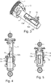
- Figur 4
- eine Seitenansicht einer Luftfederanordnung mit integrierter Steuerventilanordnung in einer oberen Luftfederhubstellung,
- Figur 5
- eine Seitenansicht einer Luftfederanordnung mit integrierter Steuerventilanordnung in einer unteren Luftfederhubstellung.
- Gemäß
Figur 1 besteht die Luftfederanordnung im Wesentlichen aus einem Außenrohr 1 mit oberer Befestigungsöse 2 zur Anbringung an ein Fahrerhaus eines nicht weiter dargestellten Nutzfahrzeuges sowie einem Abrollrohr 3 mit unterer Befestigungsöse 4 zur Anbringung in der Luftfederanordnung an einem Fahrgestell des Nutzfahrzeuges. Das Außenrohr 1 ist mit dem Abrollrohr 3 durch einen Luftfederbalg 5 verbunden, so dass sich zwischen dem Außenrohr 1, dem Abrollrohr 3 und dem Luftfederbalg 5 eine Federdruckkammer 6 bildet. Die Luftfeder wirkt mit einem integriertem hydraulischen Stoßdämpfer 7 zusammen, welcher zum Abdämpfen der gefederten Masse dient. - Die Federdruckkammer 6 der Luftfederanordnung lässt sich über eine integrierte Steuerventilanordnung, bestehend aus einem einzelnen Belüftungsventil 8 und einem einzelnen Entlüftungsventil 9, je nach Belastung mit Druckluft beaufschlagen. Das Belüftungsventil 8 und das Entlüftungsventil 9 sind durch ebenfalls integrierte mechanische Betätigungsmittel, umfassend einen nach Maßgabe der Luftfederhubstellung betätigten Schaltwipphebels 10 ansteuerbar.
- Gemäß
Figur 2 greift der Schaltwipphebel 10 seitens der Steuerventilanordnung mit dem einen Ende an den einander gegenüberliegenden und stirnseitig einander zugewandten Betätigungsstößel 8a des Belüftungsventils 8 sowie Betätigungsstößel 9a des Entlüftungsventils 9 an. Der Betätigungsstößel 8a des Belüftungsventils 8 ist koaxial zum Betätigungsstößel 9a des Entlüftungsventils 9 angeordnet. Das Belüftungsventil 8 und das Entlüftungsventil 9 sind als federrückgestellte monostabile 2/2-Wege-Schieberventile ausgebildet. Während das Belüftungsventil 8 einen Speisedruckanschluss P mit einem Arbeitsleitungsanschluss A zur Beaufschlagung - der nicht weiter dargestellten - Federdruckkammer verbindet, kann die Federdruckkammer mit dem Entlüftungsventil 9 entlüftet werden, indem der Arbeitsleitungsanschluss A mit einem Entlüftungsanschluss R verbunden wird. Das Belüftungsventil 8 und das Entlüftungsventil 9 sind über den Schaltwipphebel 10 wechselseitig betätigbar. Die Ansteuerung erfolgt derart, dass von den Bahnabschnitten (12a; 12b) das Belüftungsventil (8) und das Entlüftungsventil (9) zwar abhängig von der Hubbewegung der Federanordnung, aber nicht linear proportional damit geöffnet oder geschlossen werden. - Gemäß
Figur 3 wirkt der Schaltwipphebel 10 mit einem hülsenförmigen Betätigungselement 11 zusammen. Hierzu greift das der Steuerventilanordnung abgewandte Ende des Schaltwipphebels 10 in Führungsbahnen 12 ein, welche sich längs des gesamten Luftfederhubwegs der Luftfederanordnung erstrecken. Die beiden am hülsenförmigen Betätigungselement 11 einander gegenüberliegenden Führungsbahnen 12 (wovon hier lediglich eine Führungsbahn erkennbar ist) wirken mit einem gabelförmigen Ende des Schaltwipphebels 10 formschlüssig zusammen. Das Betätigungselement 11 ist seitens eines distalen Endes über eine Kugelgelenkanordnung 13 am Außenrohr 1 der Luftfederanordnung angebracht. - Die Führungsbahn 12 ist aus mehreren funktionalen Abschnitten zusammengesetzt und weist einen oberen Bahnabschnitt 12a zum Schwenken des Schaltwipphebels 10 im Bereich einer niedrigen Luftfederhubstellung, einen unteren Bahnabschnitt 12b zum Schwenken des Schaltwipphebels 10 im Bereich einer oberen Luftfederhubstellung und einen dazwischen liegenden und beide Bahnabschnitte quer verbindend verlaufenden mittleren Bahnabschnitt 12c, welcher den Schaltwipphebel 10 bei mittlerer Luftfederhubstellung in der Neutralstellung hält, so wie in
Figur 1 gezeigt. - Dem gegenüber befindet sich gemäß
Figur 4 der Schaltwipphebel 10 im Bereich des unteren Bahnabschnitts 12b. Diese Stellung des Schaltwipphebels 10 wird im Bereich der oberen Luftfederhubstellung erreicht, bei welcher das Außenrohr 1 gegenüber dem Abrollrohr 3 ausgefahren ist. Im Bereich dieser oberen Luftfederhubstellung wird das Entlüftungsventil 9 betätigt und das Belüftungsventil 8 bleibt unbetätigt. In Folge dessen findet eine Entlüftung der - hier nicht weiter dargestellten - Federdruckkammer zur Absenkung des Luftfederniveaus statt. - Bei der in
Figur 5 dargestellten niedrigen Luftfederhubstellung befindet sich das Außenrohr 1 gegenüber dem Abrollrohr 3 in der eingefahrenen Position. Hierbei gelangt der Schaltwipphebel 10 in den Bereich des oberen Bahnabschnittes 12a, wodurch das Belüftungsventil 8 betätigt wird und das Entlüftungsventil 9 in der unbetätigten Schaltstellung verbleibt. In Folge dessen findet eine Belüftung der - hier ebenfalls nicht weiter dargestellten - Federdruckkammer zur Anhebung des Luftfederniveaus statt. -
- 1
- Außenrohr
- 2
- Befestigungsöse
- 3
- Abrollrohr
- 4
- Befestigungsöse
- 5
- Luftfederbalg
- 6
- Federdruckkammer
- 7
- Stoßdämpfer
- 8
- Belüftungsventil
- 9
- Entlüftungsventil
- 10
- Schaltwipphebel
- 11
- Befestigungselement
- 12
- Führungsbahn (-abschnitt)
- 13
- Kugelgelenkanordnung
- A
- Arbeitsleitungsanschluss
- P
- Speisedruckanschluss
- R
- Entlüftungsanschluss
Claims (13)
- Luftfederanordnung mit einer integrierten Steuerventilanordnung zur Druckluftbeaufschlagung einer zwischen einem Außenrohr (1), einem Abrollrohr (3) und einem diese Bauteile verbindenden Luftfederbalg (5) gebildeten Federdruckkammer (6), wobei die Steuerventilanordnung aus einem einzelnen Belüftungsventil (8) und einem einzelnen Entlüftungsventil (9) besteht, die durch ebenfalls integrierte mechanische Betätigungsmittel nach Maßgabe der Luftfederhubstellung zum Be- oder Entlüften der Federdruckkammer (6) betätigbar sind,
dadurch gekennzeichnet, dass das Belüftungsventil (8) gegenüberliegend dem Entlüftungsventil (9) mit einander zugewandten Betätigungsstößeln (8a; 9a) seitens des Außenrohres (1) oder des Abrollrohres (3) angeordnet ist, wobei die dazwischenliegend hierauf einwirkenden mechanischen Betätigungsmittel einen Schaltwipphebel (10) umfassen, der mit dem einen Ende mit mindestens einer Führungsbahn (12) eines am Abrollrohr (3) bzw. Außenrohr (1) angebrachten Betätigungselements (11) eingreift, um mit dem anderen Ende auf die Betätigungsstößel (8a, 8b) zum Schalten der Steuerventilanordnung einzuwirken. - Luftfederanordnung nach Anspruch 1,
dadurch gekennzeichnet, dass sich die Führungsbahn (12) des Betätigungselements (11) über den gesamten Luftfederhubweg erstreckt. - Luftfederanordnung nach Anspruch 1,
dadurch gekennzeichnet, dass die Betätigungsstößel (8a; 9a) von Belüftungsventil (8) und Entlüftungsventil (9) koaxial zueinander angeordnet sind. - Luftfederanordnung nach Anspruch 1,
dadurch gekennzeichnet, dass das Belüftungsventil (8) und das Entlüftungsventil (9) als federrückgestellte monostabile 2/2-Wege-Ventil in Schieber- oder Sitzventilbauweise ausgebildet sind. - Luftfederanordnung nach Anspruch 1,
dadurch gekennzeichnet, dass sich die geöffneten Strömungsquerschnitte des Belüftungsventils (8) und/oder des Entlüftungsventils (9) abhängig von der linearen Bewegung der schieberartigen Betätigungsstößels (8a; 9a) ändern. - Luftfederanordnung nach Anspruch 1,
dadurch gekennzeichnet, dass das Betätigungselement (11) seitens eines distalen Endes über eine zu der Längsachse der Luftfederanordnung koaxialen Kugelgelenkanordnung (13) am Außenrohr (1) angebracht ist. - Luftfederanordnung nach Anspruch 1,
dadurch gekennzeichnet, dass das Betätigungselement (11) in dem Abrollrohr (3) gegen Verdrehung um die Längsachse der Luftfederungsanordnung gesichert geführt ist. - Luftfederanordnung nach Anspruch 1,
dadurch gekennzeichnet, dass das Betätigungselement (11) hülsenförmig ausgebildet ist und zwei einander an der Mantelfläche gegenüberliegend angeordnete Führungsbahnen (12) aufweist. - Luftfederanordnung nach Anspruch 6,
dadurch gekennzeichnet, dass die beiden einander gegenüberliegenden Führungsbahnen (12) des Betätigungselements (11) mit einem gabelförmigen Ende des Schaltwipphebel (10) formschlüssig zusammenwirken. - Luftfederanordnung nach Anspruch 1,
dadurch gekennzeichnet, dass die mindestens einer Führungsbahn (12) einen dem Belüftungsventil (8) zugeordneten oberen Bahnabschnitt (12a) zum Schwenken des Schaltwipphebels (10) im Bereich einer niedrigen Luftfederhubstellung in die Betätigungsrichtung des Belüftungsventils (8) umfasst, wobei das Entlüftungsventils (9) unbetätigt bleibt. - Luftfederanordnung nach Anspruch 1,
dadurch gekennzeichnet, dass die mindestens einer Führungsbahn (12) einen dem Entlüftungsventil (9) zugeordneten unteren Bahnabschnitt (12b) zum Schwenken des Schaltwipphebels (10) im Bereich einer oberen Luftfederhubstellung in die Betätigungsrichtung des Entlüftungsventils (9) umfasst, wobei das Belüftungsventils (8) unbetätigt bleibt. - Luftfederanordnung nach Anspruch 10 und 11,
dadurch gekennzeichnet, dass von den Bahnabschnitten (12a; 12b) das Belüftungsventil (8) und/oder das Entlüftungsventil (9) zwar abhängig von der Hubbewegung der Federanordnung, aber nicht linear proportional damit geöffnet oder geschlossen werden. - Luftfederanordnung nach Anspruch 8 und 9,
dadurch gekennzeichnet, dass zwischen dem unteren und dem oberen Bahnabschnitt (12b; 12a) ein diese verbindender mittlerer Bahnabschnitt (12c) vorgesehen ist, welcher den Schaltwipphebel (10) bei mittlerer Luftfederhubstellung in einer Neutralstellung hält, um weder das Belüftungsventil (8) noch das Entlüftungsventil (9) zu betätigen.
Applications Claiming Priority (2)
| Application Number | Priority Date | Filing Date | Title |
|---|---|---|---|
| DE102014101279.8A DE102014101279A1 (de) | 2014-02-03 | 2014-02-03 | Luftfederanordnung mit integriertem Steuerventil und wippenförmigem Betätigungsmittel |
| PCT/EP2015/052059 WO2015114134A1 (de) | 2014-02-03 | 2015-02-02 | Luftfederanordnung mit integriertem steuerventil und wippenförmigem betätigungsmittel |
Publications (2)
| Publication Number | Publication Date |
|---|---|
| EP3102445A1 EP3102445A1 (de) | 2016-12-14 |
| EP3102445B1 true EP3102445B1 (de) | 2017-10-25 |
Family
ID=52446366
Family Applications (1)
| Application Number | Title | Priority Date | Filing Date |
|---|---|---|---|
| EP15702462.1A Active EP3102445B1 (de) | 2014-02-03 | 2015-02-02 | Luftfederanordnung mit integriertem steuerventil und wippenförmigem betätigungsmittel |
Country Status (5)
| Country | Link |
|---|---|
| EP (1) | EP3102445B1 (de) |
| CN (1) | CN106061766B (de) |
| DE (1) | DE102014101279A1 (de) |
| RU (1) | RU2636625C1 (de) |
| WO (1) | WO2015114134A1 (de) |
Families Citing this family (3)
| Publication number | Priority date | Publication date | Assignee | Title |
|---|---|---|---|---|
| CN113062945B (zh) * | 2021-04-30 | 2022-12-23 | 济南弋泽展特机械有限公司 | 一种空气弹簧减振器长度调节阀 |
| CN114135618B (zh) * | 2021-11-26 | 2023-02-28 | 湖北惠工精机科技有限公司 | 一种空气弹簧集成的高度阀 |
| CN114542599B (zh) * | 2022-02-15 | 2023-12-26 | 浙江正裕工业股份有限公司 | 一种滑块装配总成、气囊装配总成及减震器 |
Family Cites Families (16)
| Publication number | Priority date | Publication date | Assignee | Title |
|---|---|---|---|---|
| US2978256A (en) * | 1957-07-11 | 1961-04-04 | Gen Motors Corp | Dual height suspension control mechanism |
| US2916298A (en) * | 1957-10-02 | 1959-12-08 | Mcmullin Harold Breniman | Air suspension means for vehicles |
| DE4409252C2 (de) * | 1994-03-18 | 1997-04-10 | Fichtel & Sachs Ag | Luftfederungsanlage |
| DE10003045C2 (de) * | 1999-03-16 | 2002-05-02 | Zf Sachs Ag | Luftfederungsanlage |
| DE10003054A1 (de) | 2000-01-25 | 2001-07-26 | Josef Bobinger | Vorrichtung zum Zerkleinern von Schnittgut, vorzugsweise von Holz |
| DE10129143C1 (de) * | 2001-06-16 | 2002-06-13 | Haldex Brake Prod Gmbh | Pneumatisches Schaltventil für Anlagen zum Heben und Senken des Fahrzeugaufbaus von luftgefederten Fahrzeugen |
| DE10200553C1 (de) | 2002-01-09 | 2003-07-31 | Zf Sachs Ag | Luftfeder mit integriertem Steuerventil |
| US20060237884A1 (en) * | 2003-06-04 | 2006-10-26 | Arvinmeritor Technology, Llc | Vehicle suspension damper with integral height leveling valve |
| DE102008002222B3 (de) * | 2008-06-05 | 2009-11-19 | Zf Friedrichshafen Ag | Luftfeder mit integriertem Steuerventil |
| FR2948608B1 (fr) * | 2009-07-30 | 2011-09-30 | Wabco France | Suspension pneumatique et utilisation pour cabine de camion |
| KR20110048180A (ko) * | 2009-11-02 | 2011-05-11 | 주식회사 만도 | 공기현가장치 |
| DE102009046290B3 (de) * | 2009-11-02 | 2011-07-14 | Haldex Brake Products GmbH, 69123 | Kabinenluftfedermodul |
| DE102010012346B4 (de) | 2010-03-22 | 2021-01-07 | Knorr-Bremse Systeme für Nutzfahrzeuge GmbH | Luftfederanordnung mit integriertem Steuerventil |
| DE102011108249B4 (de) * | 2011-07-22 | 2013-10-24 | Carl Freudenberg Kg | Luftfeder mit einer Steuereinrichtung zur Steuerung der Niveaulage eines Fahrzeugs bzw. einer Fahrerkabine |
| DE102011114570B4 (de) * | 2011-09-30 | 2016-12-15 | Vibracoustic Cv Air Springs Gmbh | Luftfederanordnung oder Luftfederdämpfer mit integrierter Ventilsteuerung |
| CN202703168U (zh) * | 2012-05-30 | 2013-01-30 | 安路普(北京)汽车技术有限公司 | 一种空气悬架 |
-
2014
- 2014-02-03 DE DE102014101279.8A patent/DE102014101279A1/de not_active Ceased
-
2015
- 2015-02-02 RU RU2016135650A patent/RU2636625C1/ru active
- 2015-02-02 WO PCT/EP2015/052059 patent/WO2015114134A1/de active Application Filing
- 2015-02-02 EP EP15702462.1A patent/EP3102445B1/de active Active
- 2015-02-02 CN CN201580006998.9A patent/CN106061766B/zh active Active
Non-Patent Citations (1)
| Title |
|---|
| None * |
Also Published As
| Publication number | Publication date |
|---|---|
| CN106061766A (zh) | 2016-10-26 |
| WO2015114134A1 (de) | 2015-08-06 |
| DE102014101279A1 (de) | 2015-08-06 |
| CN106061766B (zh) | 2018-03-27 |
| EP3102445A1 (de) | 2016-12-14 |
| RU2636625C1 (ru) | 2017-11-24 |
Similar Documents
| Publication | Publication Date | Title |
|---|---|---|
| EP2550168B1 (de) | Luftfederanordnung mit integriertem steuerventil | |
| EP1986874B2 (de) | Ventileinrichtung zur manuellen veränderung der niveaulage eines luftgefederten fahrzeuges | |
| DE19801055C1 (de) | Hydropneumatische Feder | |
| WO2007033718A1 (de) | Stabilisator-baugruppe für ein kraftfahrzeug | |
| EP1750958A1 (de) | Stabilisatoranordnung für ein kraftfahrzeug mit verstellbarer pendelstütze | |
| EP1327539A2 (de) | Luftfederbein für Kraftfahrzeuge | |
| EP3102445B1 (de) | Luftfederanordnung mit integriertem steuerventil und wippenförmigem betätigungsmittel | |
| DE10003045C2 (de) | Luftfederungsanlage | |
| WO2007033626A1 (de) | Federvorrichtung, insbesondere für einen fahrersitz | |
| EP2897821B1 (de) | Luftfederanordnung mit integriertem steuerventil | |
| EP3102446B1 (de) | Luftfederanordnung mit integriertem steuerventil und stangenförmigem betätigungsmittel | |
| EP0398008B1 (de) | Eingangsseitig mit einem Niveauregelventil verbindbares sowie auch elektrisch ansteuerbares Schaltventil mit den Stellungen Heben, Senken, Fahrt und Stop | |
| EP2951067B1 (de) | Hubzylinder zur betätigung einer magnetschienenbremse | |
| DE19648859C2 (de) | Selbstpumpendes hydropneumatisches Federbein mit innerer Niveauregelung | |
| DE102007052038A1 (de) | Hydraulischer Stabilisator, insbesondere für Fahrwerke und Fahrerhausauflagerungen | |
| DE10330877B4 (de) | Fahrwerkslager | |
| DE102018215138A1 (de) | Aktive federungsvorrichtung | |
| DE19529389C2 (de) | Selbstpumpendes hydropneumatisches Federbein mit innerer Niveauregulierung | |
| DE102017003400A1 (de) | Dreistellungsaktuator für ein automatisiertes Schaltgetriebe | |
| DE102008017763B4 (de) | Selbstpumpende hydropneumatische Feder-Dämpfer-Einheit | |
| DE928932C (de) | Abfederung eines Fahrzeugaufbaus | |
| EP1321318B1 (de) | Hydropneumatische Feder | |
| DE1110026B (de) | Verzoegerungsventil fuer im offenen System arbeitende pneumatische Federungen, insbesondere fuer Fahrzeuge | |
| DE102012201679A1 (de) | Anhebesystem für eine Achse eines Fahrzeugs |
Legal Events
| Date | Code | Title | Description |
|---|---|---|---|
| PUAI | Public reference made under article 153(3) epc to a published international application that has entered the european phase |
Free format text: ORIGINAL CODE: 0009012 |
|
| 17P | Request for examination filed |
Effective date: 20160905 |
|
| AK | Designated contracting states |
Kind code of ref document: A1 Designated state(s): AL AT BE BG CH CY CZ DE DK EE ES FI FR GB GR HR HU IE IS IT LI LT LU LV MC MK MT NL NO PL PT RO RS SE SI SK SM TR |
|
| AX | Request for extension of the european patent |
Extension state: BA ME |
|
| RIN1 | Information on inventor provided before grant (corrected) |
Inventor name: KANTOR, KORNEL Inventor name: DALI, ISTVAN Inventor name: VASS, ZOLTAN Inventor name: KONCZ, LASZLO |
|
| DAX | Request for extension of the european patent (deleted) | ||
| GRAP | Despatch of communication of intention to grant a patent |
Free format text: ORIGINAL CODE: EPIDOSNIGR1 |
|
| INTG | Intention to grant announced |
Effective date: 20170623 |
|
| GRAS | Grant fee paid |
Free format text: ORIGINAL CODE: EPIDOSNIGR3 |
|
| GRAA | (expected) grant |
Free format text: ORIGINAL CODE: 0009210 |
|
| AK | Designated contracting states |
Kind code of ref document: B1 Designated state(s): AL AT BE BG CH CY CZ DE DK EE ES FI FR GB GR HR HU IE IS IT LI LT LU LV MC MK MT NL NO PL PT RO RS SE SI SK SM TR |
|
| REG | Reference to a national code |
Ref country code: GB Ref legal event code: FG4D Free format text: NOT ENGLISH |
|
| REG | Reference to a national code |
Ref country code: CH Ref legal event code: EP |
|
| REG | Reference to a national code |
Ref country code: AT Ref legal event code: REF Ref document number: 939567 Country of ref document: AT Kind code of ref document: T Effective date: 20171115 |
|
| REG | Reference to a national code |
Ref country code: IE Ref legal event code: FG4D Free format text: LANGUAGE OF EP DOCUMENT: GERMAN |
|
| REG | Reference to a national code |
Ref country code: DE Ref legal event code: R096 Ref document number: 502015002196 Country of ref document: DE |
|
| REG | Reference to a national code |
Ref country code: SE Ref legal event code: TRGR |
|
| REG | Reference to a national code |
Ref country code: FR Ref legal event code: PLFP Year of fee payment: 4 |
|
| REG | Reference to a national code |
Ref country code: NL Ref legal event code: MP Effective date: 20171025 |
|
| REG | Reference to a national code |
Ref country code: LT Ref legal event code: MG4D |
|
| PG25 | Lapsed in a contracting state [announced via postgrant information from national office to epo] |
Ref country code: NL Free format text: LAPSE BECAUSE OF FAILURE TO SUBMIT A TRANSLATION OF THE DESCRIPTION OR TO PAY THE FEE WITHIN THE PRESCRIBED TIME-LIMIT Effective date: 20171025 |
|
| PG25 | Lapsed in a contracting state [announced via postgrant information from national office to epo] |
Ref country code: LT Free format text: LAPSE BECAUSE OF FAILURE TO SUBMIT A TRANSLATION OF THE DESCRIPTION OR TO PAY THE FEE WITHIN THE PRESCRIBED TIME-LIMIT Effective date: 20171025 Ref country code: FI Free format text: LAPSE BECAUSE OF FAILURE TO SUBMIT A TRANSLATION OF THE DESCRIPTION OR TO PAY THE FEE WITHIN THE PRESCRIBED TIME-LIMIT Effective date: 20171025 Ref country code: NO Free format text: LAPSE BECAUSE OF FAILURE TO SUBMIT A TRANSLATION OF THE DESCRIPTION OR TO PAY THE FEE WITHIN THE PRESCRIBED TIME-LIMIT Effective date: 20180125 Ref country code: ES Free format text: LAPSE BECAUSE OF FAILURE TO SUBMIT A TRANSLATION OF THE DESCRIPTION OR TO PAY THE FEE WITHIN THE PRESCRIBED TIME-LIMIT Effective date: 20171025 |
|
| PG25 | Lapsed in a contracting state [announced via postgrant information from national office to epo] |
Ref country code: BG Free format text: LAPSE BECAUSE OF FAILURE TO SUBMIT A TRANSLATION OF THE DESCRIPTION OR TO PAY THE FEE WITHIN THE PRESCRIBED TIME-LIMIT Effective date: 20180125 Ref country code: GR Free format text: LAPSE BECAUSE OF FAILURE TO SUBMIT A TRANSLATION OF THE DESCRIPTION OR TO PAY THE FEE WITHIN THE PRESCRIBED TIME-LIMIT Effective date: 20180126 Ref country code: HR Free format text: LAPSE BECAUSE OF FAILURE TO SUBMIT A TRANSLATION OF THE DESCRIPTION OR TO PAY THE FEE WITHIN THE PRESCRIBED TIME-LIMIT Effective date: 20171025 Ref country code: LV Free format text: LAPSE BECAUSE OF FAILURE TO SUBMIT A TRANSLATION OF THE DESCRIPTION OR TO PAY THE FEE WITHIN THE PRESCRIBED TIME-LIMIT Effective date: 20171025 Ref country code: IS Free format text: LAPSE BECAUSE OF FAILURE TO SUBMIT A TRANSLATION OF THE DESCRIPTION OR TO PAY THE FEE WITHIN THE PRESCRIBED TIME-LIMIT Effective date: 20180225 Ref country code: RS Free format text: LAPSE BECAUSE OF FAILURE TO SUBMIT A TRANSLATION OF THE DESCRIPTION OR TO PAY THE FEE WITHIN THE PRESCRIBED TIME-LIMIT Effective date: 20171025 |
|
| REG | Reference to a national code |
Ref country code: DE Ref legal event code: R097 Ref document number: 502015002196 Country of ref document: DE |
|
| PG25 | Lapsed in a contracting state [announced via postgrant information from national office to epo] |
Ref country code: CZ Free format text: LAPSE BECAUSE OF FAILURE TO SUBMIT A TRANSLATION OF THE DESCRIPTION OR TO PAY THE FEE WITHIN THE PRESCRIBED TIME-LIMIT Effective date: 20171025 Ref country code: EE Free format text: LAPSE BECAUSE OF FAILURE TO SUBMIT A TRANSLATION OF THE DESCRIPTION OR TO PAY THE FEE WITHIN THE PRESCRIBED TIME-LIMIT Effective date: 20171025 Ref country code: SK Free format text: LAPSE BECAUSE OF FAILURE TO SUBMIT A TRANSLATION OF THE DESCRIPTION OR TO PAY THE FEE WITHIN THE PRESCRIBED TIME-LIMIT Effective date: 20171025 Ref country code: CY Free format text: LAPSE BECAUSE OF FAILURE TO SUBMIT A TRANSLATION OF THE DESCRIPTION OR TO PAY THE FEE WITHIN THE PRESCRIBED TIME-LIMIT Effective date: 20171025 Ref country code: DK Free format text: LAPSE BECAUSE OF FAILURE TO SUBMIT A TRANSLATION OF THE DESCRIPTION OR TO PAY THE FEE WITHIN THE PRESCRIBED TIME-LIMIT Effective date: 20171025 |
|
| PG25 | Lapsed in a contracting state [announced via postgrant information from national office to epo] |
Ref country code: SM Free format text: LAPSE BECAUSE OF FAILURE TO SUBMIT A TRANSLATION OF THE DESCRIPTION OR TO PAY THE FEE WITHIN THE PRESCRIBED TIME-LIMIT Effective date: 20171025 Ref country code: PL Free format text: LAPSE BECAUSE OF FAILURE TO SUBMIT A TRANSLATION OF THE DESCRIPTION OR TO PAY THE FEE WITHIN THE PRESCRIBED TIME-LIMIT Effective date: 20171025 |
|
| PLBE | No opposition filed within time limit |
Free format text: ORIGINAL CODE: 0009261 |
|
| STAA | Information on the status of an ep patent application or granted ep patent |
Free format text: STATUS: NO OPPOSITION FILED WITHIN TIME LIMIT |
|
| REG | Reference to a national code |
Ref country code: CH Ref legal event code: PL |
|
| PG25 | Lapsed in a contracting state [announced via postgrant information from national office to epo] |
Ref country code: MT Free format text: LAPSE BECAUSE OF FAILURE TO SUBMIT A TRANSLATION OF THE DESCRIPTION OR TO PAY THE FEE WITHIN THE PRESCRIBED TIME-LIMIT Effective date: 20171025 Ref country code: MC Free format text: LAPSE BECAUSE OF FAILURE TO SUBMIT A TRANSLATION OF THE DESCRIPTION OR TO PAY THE FEE WITHIN THE PRESCRIBED TIME-LIMIT Effective date: 20171025 |
|
| 26N | No opposition filed |
Effective date: 20180726 |
|
| REG | Reference to a national code |
Ref country code: IE Ref legal event code: MM4A |
|
| PG25 | Lapsed in a contracting state [announced via postgrant information from national office to epo] |
Ref country code: CH Free format text: LAPSE BECAUSE OF NON-PAYMENT OF DUE FEES Effective date: 20180228 Ref country code: LI Free format text: LAPSE BECAUSE OF NON-PAYMENT OF DUE FEES Effective date: 20180228 Ref country code: SI Free format text: LAPSE BECAUSE OF FAILURE TO SUBMIT A TRANSLATION OF THE DESCRIPTION OR TO PAY THE FEE WITHIN THE PRESCRIBED TIME-LIMIT Effective date: 20171025 Ref country code: LU Free format text: LAPSE BECAUSE OF NON-PAYMENT OF DUE FEES Effective date: 20180202 |
|
| PG25 | Lapsed in a contracting state [announced via postgrant information from national office to epo] |
Ref country code: IE Free format text: LAPSE BECAUSE OF NON-PAYMENT OF DUE FEES Effective date: 20180202 |
|
| PG25 | Lapsed in a contracting state [announced via postgrant information from national office to epo] |
Ref country code: TR Free format text: LAPSE BECAUSE OF FAILURE TO SUBMIT A TRANSLATION OF THE DESCRIPTION OR TO PAY THE FEE WITHIN THE PRESCRIBED TIME-LIMIT Effective date: 20171025 |
|
| PG25 | Lapsed in a contracting state [announced via postgrant information from national office to epo] |
Ref country code: PT Free format text: LAPSE BECAUSE OF FAILURE TO SUBMIT A TRANSLATION OF THE DESCRIPTION OR TO PAY THE FEE WITHIN THE PRESCRIBED TIME-LIMIT Effective date: 20171025 |
|
| PG25 | Lapsed in a contracting state [announced via postgrant information from national office to epo] |
Ref country code: RO Free format text: LAPSE BECAUSE OF FAILURE TO SUBMIT A TRANSLATION OF THE DESCRIPTION OR TO PAY THE FEE WITHIN THE PRESCRIBED TIME-LIMIT Effective date: 20171025 Ref country code: MK Free format text: LAPSE BECAUSE OF NON-PAYMENT OF DUE FEES Effective date: 20171025 Ref country code: HU Free format text: LAPSE BECAUSE OF FAILURE TO SUBMIT A TRANSLATION OF THE DESCRIPTION OR TO PAY THE FEE WITHIN THE PRESCRIBED TIME-LIMIT; INVALID AB INITIO Effective date: 20150202 |
|
| PG25 | Lapsed in a contracting state [announced via postgrant information from national office to epo] |
Ref country code: AL Free format text: LAPSE BECAUSE OF FAILURE TO SUBMIT A TRANSLATION OF THE DESCRIPTION OR TO PAY THE FEE WITHIN THE PRESCRIBED TIME-LIMIT Effective date: 20171025 |
|
| REG | Reference to a national code |
Ref country code: AT Ref legal event code: MM01 Ref document number: 939567 Country of ref document: AT Kind code of ref document: T Effective date: 20200202 |
|
| PGFP | Annual fee paid to national office [announced via postgrant information from national office to epo] |
Ref country code: IT Payment date: 20210226 Year of fee payment: 7 Ref country code: FR Payment date: 20210218 Year of fee payment: 7 |
|
| PG25 | Lapsed in a contracting state [announced via postgrant information from national office to epo] |
Ref country code: AT Free format text: LAPSE BECAUSE OF NON-PAYMENT OF DUE FEES Effective date: 20200202 |
|
| PGFP | Annual fee paid to national office [announced via postgrant information from national office to epo] |
Ref country code: SE Payment date: 20210222 Year of fee payment: 7 Ref country code: GB Payment date: 20210222 Year of fee payment: 7 Ref country code: BE Payment date: 20210218 Year of fee payment: 7 |
|
| REG | Reference to a national code |
Ref country code: SE Ref legal event code: EUG |
|
| REG | Reference to a national code |
Ref country code: BE Ref legal event code: MM Effective date: 20220228 |
|
| GBPC | Gb: european patent ceased through non-payment of renewal fee |
Effective date: 20220202 |
|
| PG25 | Lapsed in a contracting state [announced via postgrant information from national office to epo] |
Ref country code: SE Free format text: LAPSE BECAUSE OF NON-PAYMENT OF DUE FEES Effective date: 20220203 |
|
| PG25 | Lapsed in a contracting state [announced via postgrant information from national office to epo] |
Ref country code: FR Free format text: LAPSE BECAUSE OF NON-PAYMENT OF DUE FEES Effective date: 20220228 |
|
| PG25 | Lapsed in a contracting state [announced via postgrant information from national office to epo] |
Ref country code: GB Free format text: LAPSE BECAUSE OF NON-PAYMENT OF DUE FEES Effective date: 20220202 |
|
| PG25 | Lapsed in a contracting state [announced via postgrant information from national office to epo] |
Ref country code: BE Free format text: LAPSE BECAUSE OF NON-PAYMENT OF DUE FEES Effective date: 20220228 |
|
| PG25 | Lapsed in a contracting state [announced via postgrant information from national office to epo] |
Ref country code: IT Free format text: LAPSE BECAUSE OF NON-PAYMENT OF DUE FEES Effective date: 20220202 |
|
| PGFP | Annual fee paid to national office [announced via postgrant information from national office to epo] |
Ref country code: DE Payment date: 20230216 Year of fee payment: 9 |
|
| P01 | Opt-out of the competence of the unified patent court (upc) registered |
Effective date: 20230508 |