EP2447006B1 - Power tool with a light for illuminating a workpiece - Google Patents
Power tool with a light for illuminating a workpiece Download PDFInfo
- Publication number
- EP2447006B1 EP2447006B1 EP11183126.9A EP11183126A EP2447006B1 EP 2447006 B1 EP2447006 B1 EP 2447006B1 EP 11183126 A EP11183126 A EP 11183126A EP 2447006 B1 EP2447006 B1 EP 2447006B1
- Authority
- EP
- European Patent Office
- Prior art keywords
- power tool
- transmission
- light
- output spindle
- coupled
- Prior art date
- Legal status (The legal status is an assumption and is not a legal conclusion. Google has not performed a legal analysis and makes no representation as to the accuracy of the status listed.)
- Active
Links
- 230000005540 biological transmission Effects 0.000 claims description 39
- 239000012636 effector Substances 0.000 claims description 26
- 238000004804 winding Methods 0.000 claims description 26
- 230000007246 mechanism Effects 0.000 claims description 11
- 230000033001 locomotion Effects 0.000 claims description 8
- 230000009467 reduction Effects 0.000 claims description 5
- 230000008878 coupling Effects 0.000 claims 2
- 238000010168 coupling process Methods 0.000 claims 2
- 238000005859 coupling reaction Methods 0.000 claims 2
- 239000000969 carrier Substances 0.000 claims 1
- XLDBTRJKXLKYTC-UHFFFAOYSA-N 2,3,4,4'-tetrachlorobiphenyl Chemical compound C1=CC(Cl)=CC=C1C1=CC=C(Cl)C(Cl)=C1Cl XLDBTRJKXLKYTC-UHFFFAOYSA-N 0.000 description 24
- 239000004020 conductor Substances 0.000 description 12
- 238000004146 energy storage Methods 0.000 description 7
- 239000004033 plastic Substances 0.000 description 4
- 229920003023 plastic Polymers 0.000 description 4
- 238000004382 potting Methods 0.000 description 3
- 239000000853 adhesive Substances 0.000 description 2
- 230000001070 adhesive effect Effects 0.000 description 2
- 230000002411 adverse Effects 0.000 description 2
- 238000005452 bending Methods 0.000 description 2
- 239000003086 colorant Substances 0.000 description 2
- 150000001875 compounds Chemical class 0.000 description 2
- 238000010276 construction Methods 0.000 description 2
- 230000000994 depressogenic effect Effects 0.000 description 2
- 230000007613 environmental effect Effects 0.000 description 2
- 239000011810 insulating material Substances 0.000 description 2
- 230000013011 mating Effects 0.000 description 2
- 239000012780 transparent material Substances 0.000 description 2
- HOBRTVXSIVSXIA-UHFFFAOYSA-N 1,2,3,5-tetrachloro-4-phenylbenzene Chemical compound ClC1=C(Cl)C(Cl)=CC(Cl)=C1C1=CC=CC=C1 HOBRTVXSIVSXIA-UHFFFAOYSA-N 0.000 description 1
- 239000003990 capacitor Substances 0.000 description 1
- 230000008859 change Effects 0.000 description 1
- 239000000356 contaminant Substances 0.000 description 1
- 230000001419 dependent effect Effects 0.000 description 1
- 239000012777 electrically insulating material Substances 0.000 description 1
- 230000003993 interaction Effects 0.000 description 1
- 238000004519 manufacturing process Methods 0.000 description 1
- 239000000463 material Substances 0.000 description 1
- 238000000034 method Methods 0.000 description 1
- 230000037361 pathway Effects 0.000 description 1
- 229910000679 solder Inorganic materials 0.000 description 1
- 230000020347 spindle assembly Effects 0.000 description 1
- 238000009987 spinning Methods 0.000 description 1
- 230000003068 static effect Effects 0.000 description 1
- 230000001629 suppression Effects 0.000 description 1
- 230000000007 visual effect Effects 0.000 description 1
- 229910052724 xenon Inorganic materials 0.000 description 1
- FHNFHKCVQCLJFQ-UHFFFAOYSA-N xenon atom Chemical compound [Xe] FHNFHKCVQCLJFQ-UHFFFAOYSA-N 0.000 description 1
Images


Classifications
-
- B—PERFORMING OPERATIONS; TRANSPORTING
- B25—HAND TOOLS; PORTABLE POWER-DRIVEN TOOLS; MANIPULATORS
- B25B—TOOLS OR BENCH DEVICES NOT OTHERWISE PROVIDED FOR, FOR FASTENING, CONNECTING, DISENGAGING OR HOLDING
- B25B23/00—Details of, or accessories for, spanners, wrenches, screwdrivers
- B25B23/18—Devices for illuminating the head of the screw or the nut
-
- B—PERFORMING OPERATIONS; TRANSPORTING
- B23—MACHINE TOOLS; METAL-WORKING NOT OTHERWISE PROVIDED FOR
- B23B—TURNING; BORING
- B23B45/00—Hand-held or like portable drilling machines, e.g. drill guns; Equipment therefor
-
- B—PERFORMING OPERATIONS; TRANSPORTING
- B23—MACHINE TOOLS; METAL-WORKING NOT OTHERWISE PROVIDED FOR
- B23Q—DETAILS, COMPONENTS, OR ACCESSORIES FOR MACHINE TOOLS, e.g. ARRANGEMENTS FOR COPYING OR CONTROLLING; MACHINE TOOLS IN GENERAL CHARACTERISED BY THE CONSTRUCTION OF PARTICULAR DETAILS OR COMPONENTS; COMBINATIONS OR ASSOCIATIONS OF METAL-WORKING MACHINES, NOT DIRECTED TO A PARTICULAR RESULT
- B23Q17/00—Arrangements for observing, indicating or measuring on machine tools
- B23Q17/24—Arrangements for observing, indicating or measuring on machine tools using optics or electromagnetic waves
- B23Q17/2404—Arrangements for improving direct observation of the working space, e.g. using mirrors or lamps
-
- B—PERFORMING OPERATIONS; TRANSPORTING
- B25—HAND TOOLS; PORTABLE POWER-DRIVEN TOOLS; MANIPULATORS
- B25B—TOOLS OR BENCH DEVICES NOT OTHERWISE PROVIDED FOR, FOR FASTENING, CONNECTING, DISENGAGING OR HOLDING
- B25B21/00—Portable power-driven screw or nut setting or loosening tools; Attachments for drilling apparatus serving the same purpose
- B25B21/02—Portable power-driven screw or nut setting or loosening tools; Attachments for drilling apparatus serving the same purpose with means for imparting impact to screwdriver blade or nut socket
-
- B—PERFORMING OPERATIONS; TRANSPORTING
- B25—HAND TOOLS; PORTABLE POWER-DRIVEN TOOLS; MANIPULATORS
- B25B—TOOLS OR BENCH DEVICES NOT OTHERWISE PROVIDED FOR, FOR FASTENING, CONNECTING, DISENGAGING OR HOLDING
- B25B23/00—Details of, or accessories for, spanners, wrenches, screwdrivers
- B25B23/0057—Socket or nut ejector means
-
- B—PERFORMING OPERATIONS; TRANSPORTING
- B25—HAND TOOLS; PORTABLE POWER-DRIVEN TOOLS; MANIPULATORS
- B25B—TOOLS OR BENCH DEVICES NOT OTHERWISE PROVIDED FOR, FOR FASTENING, CONNECTING, DISENGAGING OR HOLDING
- B25B23/00—Details of, or accessories for, spanners, wrenches, screwdrivers
- B25B23/14—Arrangement of torque limiters or torque indicators in wrenches or screwdrivers
- B25B23/141—Mechanical overload release couplings
-
- B—PERFORMING OPERATIONS; TRANSPORTING
- B25—HAND TOOLS; PORTABLE POWER-DRIVEN TOOLS; MANIPULATORS
- B25F—COMBINATION OR MULTI-PURPOSE TOOLS NOT OTHERWISE PROVIDED FOR; DETAILS OR COMPONENTS OF PORTABLE POWER-DRIVEN TOOLS NOT PARTICULARLY RELATED TO THE OPERATIONS PERFORMED AND NOT OTHERWISE PROVIDED FOR
- B25F5/00—Details or components of portable power-driven tools not particularly related to the operations performed and not otherwise provided for
- B25F5/02—Construction of casings, bodies or handles
- B25F5/021—Construction of casings, bodies or handles with guiding devices
-
- F—MECHANICAL ENGINEERING; LIGHTING; HEATING; WEAPONS; BLASTING
- F21—LIGHTING
- F21L—LIGHTING DEVICES OR SYSTEMS THEREOF, BEING PORTABLE OR SPECIALLY ADAPTED FOR TRANSPORTATION
- F21L13/00—Electric lighting devices with built-in electric generators
-
- F—MECHANICAL ENGINEERING; LIGHTING; HEATING; WEAPONS; BLASTING
- F21—LIGHTING
- F21S—NON-PORTABLE LIGHTING DEVICES; SYSTEMS THEREOF; VEHICLE LIGHTING DEVICES SPECIALLY ADAPTED FOR VEHICLE EXTERIORS
- F21S9/00—Lighting devices with a built-in power supply; Systems employing lighting devices with a built-in power supply
- F21S9/04—Lighting devices with a built-in power supply; Systems employing lighting devices with a built-in power supply the power supply being a generator
-
- H—ELECTRICITY
- H01—ELECTRIC ELEMENTS
- H01R—ELECTRICALLY-CONDUCTIVE CONNECTIONS; STRUCTURAL ASSOCIATIONS OF A PLURALITY OF MUTUALLY-INSULATED ELECTRICAL CONNECTING ELEMENTS; COUPLING DEVICES; CURRENT COLLECTORS
- H01R39/00—Rotary current collectors, distributors or interrupters
- H01R39/64—Devices for uninterrupted current collection
-
- H—ELECTRICITY
- H02—GENERATION; CONVERSION OR DISTRIBUTION OF ELECTRIC POWER
- H02K—DYNAMO-ELECTRIC MACHINES
- H02K16/00—Machines with more than one rotor or stator
- H02K16/005—Machines with only rotors, e.g. counter-rotating rotors
-
- H—ELECTRICITY
- H02—GENERATION; CONVERSION OR DISTRIBUTION OF ELECTRIC POWER
- H02K—DYNAMO-ELECTRIC MACHINES
- H02K7/00—Arrangements for handling mechanical energy structurally associated with dynamo-electric machines, e.g. structural association with mechanical driving motors or auxiliary dynamo-electric machines
- H02K7/18—Structural association of electric generators with mechanical driving motors, e.g. with turbines
- H02K7/1807—Rotary generators
-
- H—ELECTRICITY
- H02—GENERATION; CONVERSION OR DISTRIBUTION OF ELECTRIC POWER
- H02K—DYNAMO-ELECTRIC MACHINES
- H02K7/00—Arrangements for handling mechanical energy structurally associated with dynamo-electric machines, e.g. structural association with mechanical driving motors or auxiliary dynamo-electric machines
- H02K7/10—Structural association with clutches, brakes, gears, pulleys or mechanical starters
- H02K7/116—Structural association with clutches, brakes, gears, pulleys or mechanical starters with gears
-
- H—ELECTRICITY
- H02—GENERATION; CONVERSION OR DISTRIBUTION OF ELECTRIC POWER
- H02K—DYNAMO-ELECTRIC MACHINES
- H02K7/00—Arrangements for handling mechanical energy structurally associated with dynamo-electric machines, e.g. structural association with mechanical driving motors or auxiliary dynamo-electric machines
- H02K7/14—Structural association with mechanical loads, e.g. with hand-held machine tools or fans
Definitions
- the present invention relates to a power tool with a light for illuminating a workpiece.
- Power tools are often used in a variety of conditions ranging from well-lit indoor work spaces to outside construction sites or other areas that are not always well-lit. Accordingly, it is desirable to provide a method or apparatus that permits a power tool to have a lighting feature that will illuminate the workpiece that is being machined or worked on by the power tool. Such a lighting feature will assist a user to be able to adequately see the workpiece or work area that is being worked on or machined by the power tool even in substandard light conditions.
- US 2002/0172035 discloses a power tool with a lighting device mounted on its housing to illuminate the area around the tool bit and a portion of the workpiece that will be machined by the tool bit.
- An electric light of the lighting device may be connected to a power source circuit via an electric line that includes electric wires.
- a wire guide preferably supports or retains at least a portion of the electric line.
- US 5,793,130 discloses a miniature electric generator and lighting apparatus for use in a power-driven tool.
- the apparatus includes a rotor assembly having a permanent magnet, and a stator assembly within which the shaft and magnet are received.
- the stator assembly includes a pair of electrically conductive arms extending on opposite sides of the rotor, an electrically conductive shank connecting the arms together, and a winding of electrically conductive wire presenting a pair of opposed ends.
- a lamp is connected to the ends of the winding by a circuit so that it is powered upon rotation of the shaft.
- a housing assembly supports the stator assembly 24 on the output shaft of the tool, and is secured to the tool.
- DE 2362550 discloses a drill chuck which is driven via a shaft by an electric motor disposed in a handheld drill housing.
- a light source is disposed in the chuck displaced from the axis of the drill bit and focused on the workpiece adjacent the end of the drill bit by lenses.
- the light source is powered from batteries located in the handgrip and connected to the chuck via slip rings.
- the circle of light described by the focused light source on the workpiece may be aligned by eye with a scribed circle on the workpiece and inclination of the drill away from the vertical will be manifested by distortion of the circle of light.
- DE 3831344 discloses a power tool in accordance with the preamble of Claim 1 of the appendant claims.
- the present invention provides a power tool according to Claim 1.
- the present invention provides a power tool according to Claim 9.
- An embodiment in accordance with the present invention provides a power tool having a light ring configured to shine light onto a workpiece being operated upon by the power tool.
- light emitting elements such as light emitting diodes (LEDs) are placed in an annular or ring shape around part of the end effector and are configured to shine forward to illuminate the tool or accessory held by the end effector and the workpiece being machined by the tool.
- the end effector may be a tool or accessory holder mounted to an output spindle of the tool.
- Examples of end effectors that may be used in accordance with the invention may be the 7000 Series chuck manufactured and marketed by the Jacobs Chuck Manufacturing Company of Clemson, SC and quick change chucks and bit holders similar to those which are found on products such as a DC825KA Impact Driver and the driver that is disclosed in U.S. Application Serial No. 12/394,426 and a DC815KA Impact Driver that are manufactured and marketed by the DeWalt Industrial Tool Company of Baltimore, MD.
- LED lights are discussed here as an example and do not limit embodiments in accordance with the invention to tools using LEDs.
- the LED lights, or other lighting elements, and associated parts are locked to the housing of the tool and do not rotate when the power tool is operated.
- the lights may be powered by the same power source that provides power to the power tool's motor.
- it is a battery that powers the power tool and in the case of corded tools it is AC current provided from source voltage through a cord. This AC current may be modified according to the needs of the lighting device being employed.
- a rectifer may be employed to convert AC current to DC.
- FIG. 1 shows a power driver 20.
- the power driver 20 has a housing 22.
- the housing may be of a clam shell type or any other suitable type housing.
- the power driver 20 may have a nose cone 23 located at the front portion of the power driver 20.
- a handle 24 projects downwardly from the housing 22 and is terminated with a battery 26.
- the battery 26 provides the power to turn the end effector 28.
- the end effector 28 may be configured to hold an accessory or tool such as a drill bit or a driving type accessory such as a Philips or standard screwdriver. Other types of tools or accessories may be held and used in the end effector 28 as can appreciated by one skilled in the art.
- the movement of the end effector 28 may be controlled by the trigger 30.
- the trigger 30 may selectively provide power from the battery 26 to the motor 32 located within the housing 22. In some embodiments of the invention, the more the trigger or switch 30 is depressed the more power may be applied to the motor 32 which may cause the end effector 28 to spin faster.
- the power driver 20 may be equipped with a clutch collar 34.
- Other embodiments in accordance with the invention may not have a rotating clutch collar, but rather a different rotating collar mechanism.
- the rotating collar mechanism may be a drill/hammer mode selector, a gear shifter, an on/off switch, a tool variable speed control or other rotating collar control mechanism.
- this specification will refer to a clutch collar as an example but does not limit embodiments in accordance with the invention to tools having clutch collars.
- the clutch collar 34 can provide protection for interior portions of the power driver 20, particularly the transmission and other internal components of the power driver 20 that may be mounted on the nose cone 23.
- the clutch collar 34 may be rotated to adjust the transmission.
- An example of a clutch and transmission that may work in accordance with the invention is shown in U.S. Patent No.
- a light ring 38 is located on a front portion of the power tool 20 just behind the end effector 28 in a recess 39 in the clutch collar 34.
- FIG. 2 a partial perspective view of a front portion of the power driver 20 is shown.
- An indicator 37 may be located on the nose cone 23.
- the indicator 37 may provide a reference for the user for determining the angular position of the clutch collar 34 and a reference point for comparing the numbers on the numbered scale 36.
- the light ring 38 is located within a recess 39 of the clutch collar 34.
- the light ring 38 may include a cover 40.
- the cover 40 may protect interior components of the tool from moisture or other contaminants.
- the cover 40 may include blisters 42 located on the cover 40 as to be directly over the LEDs 58 (as shown in FIG. 5 ).
- the blisters 42 may be translucent or clear in order to permit light generated by the LEDs 58 to pass through.
- the blisters 42 may direct or focus the light.
- the blisters 42 may be round, rectangular, square or any other shape.
- the blisters 42 are shaped to correspond with the shape of the lighting elements 58.
- the light may simply pass through the blisters 42.
- the remainder of the cover 40 may be a dark color. Other color schemes may be used in accordance with the invention.
- the cover 40 is held axially in place from moving in a forward direction toward the end effector 28 by retaining ring 44.
- the retaining ring 44 is mounted on a retainer 46 which is part of the nose cone 37 as better illustrated in FIGS. 13 and 14 and described in more detail later below.
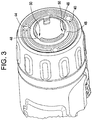
- FIG. 3 is a similar view to that shown in FIG. 2 , however, the end effector 28 is removed to better illustrate certain features associated with the retaining ring 44 and the retainer 46.
- FIG. 3 shows portions 48 of the retaining ring 44 exposed in gap 50 that would fit within the groove 52 if it were not in the gap 50.
- the retaining ring 44 fits within a groove 52 in the retainer 46. When the retaining ring 44 is placed in the groove 52 the retaining ring 44 is secured in place. The retaining ring 44 prevents the cover 40 from axially moving forward toward the end effector 28.
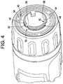
- FIG. 4 is a similar view as that shown in FIG. 3 , however, the retaining ring 44 has been removed as well as the end effector 28 to better illustrate features of the cover 40 and the retainer 46.
- the cover 40 includes tabs 56, which are located within the gaps 50 of the retainer 46. The tab 56 and gap 50 combination keep the cover 40 aligned and from rotating around the retainer 46.
- the groove 52 is also illustrated in FIG. 4 in which the retaining ring 44 is located as shown in FIG. 3 .
- FIG. 5 illustrates other aspects of the light ring 38, which are normally contained within the clutch collar 34 and located behind the cover 40.
- light emitting diodes or LEDs 58 are located at various points around the light ring 38.
- the LEDs 58 emit white light although in other embodiments the LEDs 58 might emit other colors of light.
- different LEDs on the same tool could emit different colors of light. While the embodiment shown in FIG. 5 illustrates three LEDs 58 any number of LEDs may be used in accordance with the invention including one or more.
- the LEDs 58 are mounted to a ring-shaped printed circuit board or PCB 60.
- the PCB 60 and LEDs 58 are fit into a trench 61 in the wire way 62.
- the wire way 62 and trench 61 may allow for potting of the PCB if necessary.
- the wire way 62 provides protection and structural strength for the PCB so that undue mechanical loads are not placed upon the PCB 60. Such support is desirable as a PCB 60 may be fragile and subject to breaking or malfunctioning.
- the wire way 62 may include snap-in features 64 which allow the PCB 60 to be pushed into the wire way 62 and then the snap-in features 64 snap out once the PCB 60 is located within the wire way 62.
- the snap-in features 64 prevent the PCB 60 from coming out of the wire way 62.
- the wire way 62 may include grooves 66.
- Tabs 68 located on the PCB 62 may fit within the grooves 66 within the wire way 62.
- the tabs 68 and grooves 66 combination help the PCB 60 and the wire way 62 be aligned and may prevent or resist the PCB 60 from rotating with respect to the wire way 62.
- the wire way 62 may include a PCB holding portion 70 which is generally circular in shape and a wire supporting portion 72.
- the wire supporting portion 72 may include a channel 74 which is sized and located to contain wires 76.
- the wires 76 may provide power to the PCB 60 which in turns provides power to illuminate the LEDs 58.
- the wire supporting portion 72 of the wire way 62 provides a structure for the wires 76 to be supported in and provides protection for the wires 76.
- the wires 76 may terminate with a plug 78.
- the plug 78 may fit into plug supporting structure 80 located within the wire supporting portion 72 so that the plug 78, which is made of a more rigid material than the wires 76, is held securely to the wire way 62 via the plug supporting structure 80.
- the plug 78 may be press fit into the wire supporting portion 72 of the wire way 62.
- the circuit to which the PCB 60 is connected may also include an electromagnetic surge suppression circuit (such as a zener diode) for static and over-voltage protection.
- the circuit may also include a resistor or resistors to drop the voltage from the battery pack voltage to an appropriate level for the LEDs.
- Some embodiments do not have a separate PCB, wire guide, wires and connector.
- plated plastics can be used whereby the wire guide could be first molded into a shape similar to the wire guide 62 as shown.
- tracks like on a standard PCB
- the components could then be soldered to this one piece, and would be electrically connected back to the place where the wires would connect it to the switch. This would greatly simplify the assembly.
- FIG. 6 is a partial perspective view of a bottom portion of the wire way 62.
- the wire way 62 may be equipped with a collar stopping tab 82 which will be explained in more detail below as FIG. 12 is discussed.
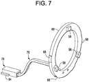
- FIG. 7 is a perspective view similar to that shown in FIG. 5 , however, the wire way 62 has been removed in order to better illustrate some of the features shown in FIG. 7 .
- the LEDs 58 are mounted onto the PCB 60.
- the PCB 60 shows the tabs 68. While the embodiments shown in the figures show five tabs 68, one skilled in the art can appreciate that other numbers of tabs or other features may be employed in order to help keep the PCB aligned and/or rotationally locked to the wire way 68.
- the wires 76 are attached to a rear portion of the PCB 60.
- the plug 78 includes the plug stopping structure 84 which butts against a portion of the wire way 68 to prevent the plug 78 from being inserted too far into the wire way 62.
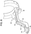
- FIG. 8 illustrates the plug stopping structure 84 located on the plug 78 butted against the wire supporting portion 72 of the wire way 62.
- the wires 76 are located within the channel 74.
- the plug 78 snaps into the wire supporting portion 72 and the wires 76 may be pressed into the channel 74 in a press fit manner to secure the wires 76 into the channel 74.
- a rear portion of the collar stopping tab 82 is also illustrated in FIG. 8 .
- FIG. 9 illustrates the housing 22 and the wire way 62.
- the nose cone 23 has been removed in order to better illustrate how the plug 78 attaches to a receiving plug 86.
- the plug 78 is slid into the receiving plug 76.
- the plug stopping structure 84 slides into slots 87 located on the receiving plug 86.
- power from the wires 88 is communicated to the wire 76.
- the joint made of the plug 78 and the receiving plug 86 provide a rigid support for the connection of the wires 76 and 88.
- the wires 88 may receive power from the battery 26 as controlled by the trigger 30.
- the wires 88 extend out of a switch body associated with the trigger 30.
- a switch body could have connectors to which the wires 88 are soldered or otherwise connected.
- the trigger switch may include electronics for variable speed control.
- the wires 88 may be soldered to a PCB located inside the switch body.
- FIG. 10 is a partial perspective view of the guide 62 showing several additional elements on the guide 62.
- a clutch adjusting nut 90 is butted against the guide 62.
- the stop tab 82 is fit into a notch 92 in the clutch adjusting nut 90.
- the notch 92 in the clutch adjusting nut 90 aligns to the stopping tab 82 on the guide 62 to assist in providing proper assembly of the threads between the adjusting nut 90 and the nose cone 23 during assembly.
- the notch 92 and the clutch adjusting nut 90 may have chamfered edges 96 to the notch walls 94.
- the chamfered edges 96 may assist in the stopping tab 82 to be seated in the notch 92 and the clutch adjusting nut 90.
- a combination of the notch 92 and the clutch adjusting nut 70 and the stopping tab 82 in combination with the other tabs and notch combinations 50, 56, 66, 68 can assure that the cover 40, the nose cone 23, the wire way 62, the PCB 60, and the clutch adjusting nut 90 are aligned with respect to each other.
- the clutch adjusting nut 90 includes a ridge 100. As shown in FIG. 10 a clutch spring 102 urges at one end against the ridge 100 and at the opposite end of the clutch spring 102, the clutch spring 102 urges against a clutch washer 104. The clutch spring 102 exerts a force on the ridge 100 of the clutch adjusting nut 90 which in turn urges the wire way 62 against the cover 40 and ultimately against the retaining ring 44. The force exerted by the clutch spring 102 keeps the light ring assembly 38 in axial position. As shown in FIG. 11 the clutch washer 104 urges against the nose cone 23.
- FIG. 11 illustrates the clutch washer 104, clutch spring 102, and the clutch adjusting nut 90 mounted to the nose cone 23.
- the clutch collar 34 is shown in a forward axial position and not yet installed on the power tool 20 in order to expose the clutch washer 104, the clutch spring 102 and the clutch adjusting nut 90.
- a tab 98 on the clutch adjusting nut 90 is scored with marks or notches 106 on one of the adjustment tabs 98.
- the scoring 106 provides a visual aid when assembling the collar 34 to properly align the clutch collar 34.
- the adjustment tab 98 on the clutch adjusting nut 90 is aligned with a desired notch 108 in the clutch collar 34. Once the desired notch 108 is aligned with the desired adjustment tab 98, the clutch collar 34 can be fitted onto the power tool 20.
- the indicator 34 and the numbered scale 36 may also provide assistance in aligning the clutch collar 34 to provide proper assembly of the clutch collar 34 onto the nose cone 23.
- FIG. 12 is a partial perspective view of the clutch collar 34 installed onto the guide 62. Other elements have been omitted from FIG. 12 in order to better show the interaction between the guide 62 and the clutch collar 34.
- the clutch collar 34 in some embodiments in accordance with the invention, is rotatable.
- the clutch collar 34 is rotatable on the power tool 20 in order to provide different torque and/or speed settings for the end effector 28. It may be desirable to limit the rotation of the clutch collar 34 in both directions to establish a maximum setting for turning the clutch collar clockwise and a maximum setting when turning the clutch collar counterclockwise as shown in FIG. 12 . Making maximum and minimum settings is, in some embodiments, accomplished by using the collar stopping tab 82 which butts against the stop 110 on the clutch collar 34.
- the wall 112 on the stop 110 butts against a wall 114 on the collar stopping tab 82 to provide a limit to clutch collar 34 rotation in a clockwise direction as viewed in FIG. 12 .
- the same stop 110 and collar stopping tab 82 provide a stop for rotating the clutch collar 34 in the opposite direction (i.e., counterclockwise as viewed in FIG. 12 ). This is accomplished when the clutch collar 34 is rotated so that the opposite wall 116 on the stop 110 butts against the opposite wall 118 on the tab 82.
- FIG. 12 also illustrates additional notches 108 in the clutch collar 34 for providing detents when the clutch collar 34 is rotated to various settings with respect to the nose cone 23.
- FIG. 13 is a partial perspective view of the guide 62 mounted onto a stem portion 120 of the nose cone 23.
- a lock portion 124 of the guide 62 fits into a groove 122 of the stem portion 120 of the nose cone 23.
- the groove 122 is sized and dimensioned so that the lock portion 124 of the wire supporting portion 72 of the guide 62 fits within the groove 122 and locks the guide 62 to be angularly fixed with respect to the nose cone 23.
- the locks 124 located on the wire supporting portion 72 of the guide 62 are wider than the rest of the wire supporting portion 72 and aid in permitting the guide 62 to be securely seated in the groove 122 of the stem portion 120 of the nose cone 23.
- a second groove 126 is in the nose cone 23 for allowing the wire supporting portion 72 of the guide 62 to fit within the groove 126 of the nose cone 23.
- the retainer 46 on the nose cone 23 and the groove 52 of the nose cone 23 are also shown forward of the guide 62. The above described features also help align the guide 62 with respect to the nose cone 23.
- the retainer 46 is integral with the stem 120 and the nose cone 23. In other embodiments of the inventions, they may be separable parts.
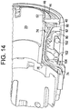
- FIG. 14 is a partial cutaway perspective view of the nose cone 23 and additional parts described below.
- FIG. 14 shows how the parts described herein are assembled together according to some embodiments of the invention.
- the transmission, spindle, and other parts associated with turning the end effector have been omitted to more clearly show the parts described herein.
- the retaining ring 44 is seated within the groove 52 of the retainer 46.
- the retaining ring 44 provides a limit of forward axial movement of the cover 40, the guide 62, and the clutch adjusting nut 90.
- the clutch spring 102 presses against the clutch washer 104 to urge the clutch adjusting nut 90 to urge the guide 62, PCB 60, and cover 40 against the retaining ring 44.
- the wires 76 are located in a channel 74 defined by the guide 62 and the nose cone 23. The wires 76 are protected from the spinning parts of the end effector mechanism.
- the light ring 38 can be used on other rotary power tools such as impact drivers, drills, hammer drills, routers.
- FIG. 15 illustrates a perspective rear view of a holder 140 that is used on a power tool that is not equipped with a collar as described in the embodiments above.
- the holder 140 holds the light ring 38.
- the light ring 38 includes the PCB 60 similar to that described above.
- the PCB 60 and the holder 140 may include snap-in features 64 similar to that described above so that the PCB 60 snaps into and is secured in the holder 140.
- a circular cover 40 may be mounted to the holder 140 in front of the PCB 60 similar to embodiments described above.
- the cover 40 may include snap-in elements that correspond with snap-in elements on the holder 140.
- the lens 40 may be secured in place with a retaining ring system similar to that described above.
- the holder 140 may attach to the nose cone 23 with snap-in elements located on both the holder 140 and the nose ring 23 similar to the snap-in features 64 described in the embodiments above.
- the light ring holder 140 may be secured in place in a variety of ways including, but not limited to, a retaining ring system similar to the embodiments described above.
- the holder 140 includes a housing portion 142, a chin shroud 144, and a wire way portion 146.
- Wires 76 connect the PCB 60 (which contains light emitting elements similar to those described above) with a plug 78.
- the holder 140 does not fully support the wires 76 along the full length of the wires 76 all the way to the plug 78. Rather, the wire way portion 146 stops at some point along the length of the wires 76, leaving the wires 76 and the plug 78 to be not supported by the holder 140.
- FIG. 16 is a partial perspective view of a power tool 147 that does not have a rotatable clutch collar but rather is equipped with the holder 140.
- the cover 40 is shown mounted in a recess in the holder 140.
- the holder 140 is mounted to the nose cone 23 which is supported by the housing 22.
- a fastener hole 148 is shown in the housing 22.
- the fastener hole 148 provides a place for a fastener such as a screw or bolt to connect the two halves of the clam shell type housing 22 together. While the fastener is not shown in FIG. 16 , it will be appreciated that when the power tool 147 is fully constructed that a fastener will be located in the fastener hole 148 to connect the two halves of the clam shell housing 22 together.
- FIG. 16 The chin shroud 144 is located on the holder 140 and provides a housing for a portion of the wires 76 so that the wires 76 are not exposed outside of the power tool 147.
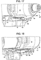
- FIGS. 17 and 18 show the power tool 147 with part of the housing 22 removed.
- the housing 22 is a clam shell type housing and one of the clam shells is removed exposing the clam shell housing 22 located on the far side of the power tool 147.
- the holder 140 is shown mounted to the nose cone 23.
- a fastener hole tube 150 located in the fastener hole 148 is shown.
- the wires 76 are routed around the hole tube 150 and are located in the interior 152 of the housing 22.
- the wires 76 are terminated with a plug 78 also located in the interior 152 of the housing 22.
- the interior 152 of the housing defines a space or pathway for the wires 76 and the plug 78.
- the chin shroud 144 defines a wire way portion 146 through which the wires 76 are strung.
- the chin shroud 144 also includes retaining structure 154 which is set in a retaining area 156 defined by the housing 22.
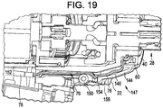
- FIG. 19 is a partial perspective cut-away view showing the end effector 28 associated with the power tool 147 extending through the cover 40 located in front of the PCB 60.
- LEDs (not shown in FIG. 19 ) are located on the PCB 60 and configured to light the tool or workpiece being worked on by the power tool 147.
- the wires 76 provide power between the PCB 60 and a power source connected via the plug 78 to power source.
- the wires 76 are located in the wire way portion 146 of the chin shroud 144 and the interior 152 of the housing 22.
- the chin shroud 144 has the retaining structure 154 located in the retaining area 156 defined by the housing 22.
- driver 20 ( Fig. 1 ) has been illustrated and described herein as including a lighting system that is disposed between a gear case and a rotating collar 34 ( Fig. 1 ) of the driver 20 ( Fig. 1 ) and/or forwardly of a housing 22 ( Fig. 1 ) and/or a gear case or nose cone 23 ( Fig. 1 ), it will be appreciated that the driver could be constructed somewhat differently.
- another driver constructed in accordance with the teachings of the present disclosure is generally indicated by reference numeral 400.
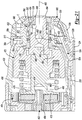
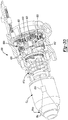
- the driver 400 can include a housing assembly 22a, a motor 402, a transmission 404, an output spindle 406, a battery pack 408 and a lighting system 410.
- the driver 400 is depicted as being an impact driver that operates the output spindle 406 in a rotary manner similar to that which is disclosed in U.S. Application Serial No. 12/769,981 .
- the driver 400 could be configured as a screwdriver, drill driver, hammer drill driver, and/or rotary hammer to provide a rotary and/or axial output or could be configured to provide an axial output (e.g., hammer).
- the housing assembly 22a can be configured to house the motor 402, the transmission 404 and at least a portion of the output spindle 406.
- the housing assembly 22a includes a clam shell housing 416, which is formed by a pair of clam shell halves, and a gear case assembly 418 that includes a first gear case member 420, a second gear case member 422, and a cover 424.
- the first gear case member 420 can define a first case portion 430 and a second case portion 432.
- the first case portion 430 can be mounted to the clam shell housing 416 and extend forwardly therefrom.
- the first case portion 430 can define an internal cavity 436 into which the transmission 404 can be received.
- the second case portion 432 can be coupled to or integrally formed with the first case portion 430 and can extend forwardly therefrom.
- the second case portion 432 can define a spindle aperture 440 and a mounting boss 442.
- the spindle aperture 440 can intersect the internal cavity 436 to define a passageway through which the output spindle can be received.
- the second gear case member 422 can define a bearing mount 450 and one or more through-holes 452.
- the bearing mount 450 can be configured to receive a spindle support bearing 454 therein.
- the second gear case member 422 can be received on the mounting boss 442 and can be secured thereto via a plurality of fasteners 456. It will be appreciated that the mounting boss 442 is configured to align the spindle support bearing 454 to the rotational axis 460 of the output spindle 406.
- the motor 402, the battery pack 408 and the transmission 404 can be conventional in their construction and operation.
- the motor 402 can be housed in the clam shell housing 416 and can be electrically coupled to the battery pack 408 through a trigger (switch) 30a.
- the battery pack 408 can be releasably coupled to the clam shell housing 416.
- the transmission 404 can be any type of transmission, such as a multi-stage planetary transmission, and can have an input member, that can be driven by an output shaft 464 of the motor 402, and an output member that can be drivingly coupled to the output spindle 406.
- the transmission 404 includes a single stage planetary reduction 470 and a Potts-type impact mechanism 472.
- a sun gear 474 associated with the planetary reduction 470 serves as the transmission input, while a planet carrier 476 associated with the planetary reduction serves as an output of the planetary reduction 470.
- the impact mechanism 472 can include an input spindle 480, which can receive rotary power from the planet carrier 476, a hammer 482, which can be mounted on the input spindle 480, a cam mechanism (not specifically shown), an impact spring 486 and an anvil 488.
- the cam mechanism can couple the hammer 482 to the input spindle 480 in a manner that permits limited rotational and axial movement of the hammer 482 relative to the input spindle 480.
- the impact spring 486 can bias the hammer 482 into a position where the cam mechanism rotatably couples the hammer 482 to the input spindle 480.
- the anvil 488 which can be mounted for rotation on the input spindle 480, is configured to engage the hammer 482 such that rotational energy in the hammer 482 can be transmitted to the anvil 488.
- the output spindle 406 can be integrally formed with the anvil 488 and can have a shaft member 490, a chuck portion 492, and a journal portion 494 that can be disposed on a side of the chuck portion 492 opposite the shaft member 490.
- the shaft member 490 can be supported for rotation about the rotational axis 460 by a bushing 500 that is disposed in the first case portion 430 of the first gear case member 420.
- the chuck portion 492 can be disposed forwardly of the first gear case member 420 and can be configured to receive a tool bit, such as a 1 ⁇ 4 inch hex bit, therein.
- the journal portion 494 can be a distal end of the output spindle 406 and can be received in the spindle support bearing 454 in the second gear case member 422 such that the end of the output spindle 406 opposite the input spindle 480 is journally supported by the second gear case member 422.
- the lighting system 410 can include a light ring 38a and a circuit assembly 510.
- the light ring 38a can comprise a holder 140a and a wireway 62a.
- the holder 140a can be formed in a generally semi-annular (e.g., horseshoe) shape that is configured to be mounted about a portion of the mechanism that unlatches the chuck or bit holder, as well as be matingly received on the mounting boss 442 of the first gear case member 420 such that the light ring 38a is rotationally fixed to the housing assembly 22a.
- the holder 140b can define a trench 61a, which can be configured to receive the circuit assembly 510, and a plurality of LED apertures 520 that can extend axially through the holder 140a in-line with the through-holes 452 in the second gear case member 422.
- the wireway 62a can define a wire channel 524, as well as an operator mount 526 that can be configured to receive there through an axially movable button 528 that can be employed to unlatch the bit holder C.
- the button 528 can be coupled to a lever 530, which is fitted to a bit holder sleeve 532, and can be biased outwardly from the clam shell housing 416 via a button spring 534.
- the bit holder sleeve 532 can be axially movably mounted on the chuck portion 492 of the output spindle 406 between a first or latched position, in which a locking ball 538 is urged radially inwardly into the hollow interior of the chuck portion 492, and a second or unlatched position in which the locking ball 538 may be moved radially outwardly so that a tool bit received in the chuck portion 492 can be withdrawn from the output spindle 406.
- the wireway 62a can effectively close an opening about the button 528 between the gear case assembly 418 and the clam shell housing 416.
- the circuit assembly 510 can include a circuit board 60a, a plurality of LED's 58a and a wire harness 550.
- the circuit board 60a can be formed of an insulating material and can include wires or conductors (not specifically shown) that can electrically couple the wire harness 550 and the LED's 58a.
- the circuit board 60a is a printed circuit board that is formed in a semi-annular shape that is configured to be received in the correspondingly shaped trench 61a formed in the light ring 38a.
- the LED's 58a can be fixedly coupled to the circuit board 60a and can be disposed in-line with the LED apertures 520 formed in the light ring 38a.
- the wire harness 550 can comprise a plurality of wires 76a and a plug 78a.
- the wires 76a can include first and second wires (not specifically shown) that can be coupled to the conductors of the circuit board 60a and to the conductors (not specifically shown) in the plug 78a to transmit electrical power between the plug 78a and the LED's 58a.
- the wires 76a can be received in the wireway 62a in the light ring 38a and can be festooned or routed through a wire channel 524 formed in the clam shell housing 416.
- the plug 78a can be configured to matingly engage a corresponding plug (not specifically shown) to electrically couple the circuit assembly 510 to a source of electrical power.
- the corresponding plug is electrically coupled to a trigger 30a that is coupled to the battery pack 408.
- the trigger 30a can be configured to transmit electrical power from the battery pack 408 to the circuit assembly 510 in a desired manner, such as during operation of the motor 402, or during operation of the motor 402, as well as for a predetermined amount of time after operation of the motor 402.
- the circuit assembly 510 can be coupled to the light ring 38a in any desired manner, including adhesives, potting compounds, clips and fasteners.
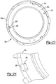
- the light ring 38a comprises a plurality of retaining tabs 560 that can extend through tab apertures 562 in the circuit board 60a.
- the tabs 560 can be initially formed to extend in an axial direction that is generally parallel to the rotational axis 460 of the output spindle 406, which can facilitate the axial translation of the circuit board 60a into the trench 61a, and can be deformed in whole or in part to retain the circuit board 60a within the trench 61a.
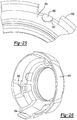
- the tabs 560 can be deformed by twisting or bending, but in the example provided, each of the tabs 560 is heated and bent over at a right angle as shown in Figure 25 so as to lie over a portion of the circuit board 60a adjacent a corresponding one of the tab apertures 562.
- the cover 424 can be fixedly coupled to the second gear case member 422 in any desired manner, such as via mating sets of ribs and grooves 590. It will be appreciated that mating features (not specifically shown) may be formed into the cover 424 and the second gear case member 422 that inhibit rotation of the cover 424 relative to the second gear case member 422 when the cover 424 is engaged to the second gear case member 422.
- the cover 424 can define a set of second through-holes 592, as well as a button stop 594.
- the set of second through-holes 592 can be disposed in-line with the through-holes 452 in the second gear case member 422 and the LED's 58a in the circuit assembly 510 such that light generated by the LED's 58a can be transmitted through the second gear case member 422 and the cover 424 to illuminate an area forwardly of the gear case assembly 418 and the output spindle 406.
- the button stop 594 can be disposed forwardly of the button 528 and can be employed to limit forward axial movement of the button 528.
- various devices may be incorporated into the driver 400.
- such devices may be located in one or both of the through-holes 452 in the second gear case member 422 and the second through-holes 592 in the cover 424.
- one or more resilient elements may be disposed between the light ring 38a and the gear case assembly 418 to generate or limit an axially directed clamping force that is exerted onto the light ring 38a.
- four resilient dampers 598 are mounted to second gear case member 422 and abut the front axial face of the light ring 38a. The resilient dampers 598 are compressed when the second gear case member 422 is fastened to the first gear case member 420 to thereby apply a clamping force to the light ring 38a that inhibits movement of the light ring 38a relative to the gear case assembly 418.
- a driver which does not form part of the invention is generally indicated by reference numeral 600.
- the driver 600 can be a drill/driver of the type that is disclosed in U.S. Patent Application Serial No. 12/610,762 , except that a lighting system is incorporated into the driver 600.
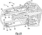
- the lighting system 410b includes a first portion 610, which can be mounted to an output spindle assembly 611, and a second portion 612 that can be coupled for rotation with a drill chuck Cb.
- the first portion 610 can comprise a set of spring contacts 620 that can be electrically coupled to a source of electrical power (e.g., to a battery pack via a trigger switch).
- the spring contacts 620 can comprise a first spring contact 620a and a second spring contact 620b that can be electrically isolated from one another.
- the first spring contact 620a can be offset in a radial direction by a first distance from a rotational axis 460b of the output spindle 406b, while the second spring contact 620b can be offset in a radial direction by a second distance that is different from the first distance.
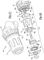
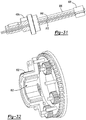
- the second portion 612 can comprise a sleeve 630, a coupler 632, a bushing 634, a holder 140b, a circuit assembly 510b, a cover 636 and a retaining ring 638.
- the sleeve 630 can be received about the chuck Cb and can be configured to receive a rotary input from an operator to open or close the jaws (not shown) of the chuck Cb.
- the chuck Cb can be any type of chuck Cb, such as a keyless chuck.
- the coupler 632 can include an annular plate 640, first and second conductor tracks 642 and 644, respectively, and a plug 78b.
- the annular plate 640 can be formed of an electrically insulating material, such as a durable relatively nonconductive plastic (i.e., a plastic that is electrically insulating when an electrical potential that is less than 50 or 100 volts is applied to it).
- the annular plate 640 can be fixedly mounted on the spindle 650 of the chuck Cb.
- the spindle 650 of the chuck Cb can be engaged to the output spindle 406b by any desired means.
- the spindle 650 of the chuck Cb is threaded onto the output spindle 406b via left-handed threads and a spindle retaining fastener 652 is fitted through the spindle 650 and threadably engaged to the output spindle 406b. Accordingly, it will be appreciated that as the spindle 650 of the chuck Cb is coupled for rotation with the output spindle 406b, the annular plate 640 will also rotate with the output spindle 406b by virtue of its connection to the spindle 650 of the chuck Cb.
- the first and second conductor tracks 642 and 644 can be mounted to a first side of the annular plate 640 and can be disposed concentrically such that they are electrically isolated from one another.
- the first and second conductor tracks 642 and 644 can be configured to electrically engage the first and second spring contacts 620a and 620b, respectively.
- the plug 78b can be fixedly coupled to a second side of the annular plate 640 and can comprise terminals (not specifically shown) that can be electrically coupled to the first and second conductor tracks 642 and 644.
- the terminals extend through the annular plate 640 so as to intersect respective portions of the first and second conductor tracks 642 and 644 and solder is employed to electrically couple the terminals and the first and second conductor tracks 642 and 644.
- the bushing 634 can be received between the spindle 650 of the chuck Cb and the sleeve 630 on a side of the chuck Cb opposite the annular plate 640.
- a slot or groove 656 can be formed in the bushing 634.
- the holder 140b can be an annular structure that can define an annular trench 61b.
- the circuit assembly 510b can include a circuit board 60b, a plurality of LED's 58b and a wire harness 550b.
- the circuit board 60b can be formed of an insulating material and can include wires or conductors (not specifically shown) that can electrically couple the wire harness 550b and the LED's 58b.
- the circuit board 60b is a printed circuit board that is formed in an annular shape that is configured to be received in the correspondingly shaped trench 61b formed in the holder 140b.
- the LED's 58b can be fixedly coupled to the circuit board 60b on a side opposite the holder 140b.
- the wire harness 550b can comprise a plurality of wires 76b including first and second wires (not specifically shown) that can be coupled to the conductors of the circuit board 60b and to the conductors (not specifically shown) in the plug 78b to transmit electrical power between the plug 78b and the LED's 58b.
- the wires 76b can be received in the radial space between the spindle 650 of the chuck Cb and the sleeve 630 and can extend longitudinally through the groove 656 in the bushing 634.
- the circuit assembly 510b can be coupled to the holder 140b in any desired manner, including adhesives, potting compounds, clips and fasteners.
- the holder 140b comprises a plurality of retaining tabs 560b that can extend through tab apertures (not specifically shown) in the circuit board 60b.
- the tabs 560b can be initially formed to extend in an axial direction that is generally parallel to the rotational axis 460b of the spindle 650 of the chuck Cb, which can facilitate the axial translation of the circuit board 60b into the trench 61b, and can be deformed in whole or in part to retain the circuit board 60b within the trench 61b.
- the tabs 560b can be deformed by twisting or bending, but in the example provided, each of the tabs 560b is heated and bent over at a right angle so as to lie over a portion of the circuit board 60b adjacent a corresponding one of the tab apertures.
- the cover 636 can be an annular structure that can be fitted to an axial end of the sleeve 630 opposite the coupler 632 and can aid in axially fixing the holder 140b in place in the sleeve 630 against a front face of the bushing 634.
- the cover 636 can be formed of a transparent material that can be clear or colored. The transparent material can be formed such that light received from the LED's 58b will exit the cover 636 in a desired manner. For example, the light exiting the cover 636 can be spread or concentrated over a desired area to illuminate one or more relatively large areas and/or one or more relatively small points.
- the retaining ring 638 can be received in a ring groove 680 in the spindle 650 of the chuck Cb and can be configured to limit forward motion of the cover 636 relative to the sleeve 630 to thereby maintain the cover 636 on the spindle 650 of the chuck Cb.
- the driver 800 can be a drill driver of the type that is disclosed in U.S. Pat. No. 12/610,762 , except that a lighting system is incorporated into the tool.
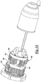
- the lighting system 410c includes a generator 810, a conductive connector 812, an energy storage device 814 and a circuit assembly 510c.
- the generator 810 can comprise one or more field windings 820 and one or more sets of magnets 822.
- the field winding(s) 820 can be mounted on a generator shaft portion 826 of the output spindle 406c of the driver 800.
- the output spindle 406c can be coupled (e.g., via a spindle lock) to an output member of an output stage 830 of a multi-stage planetary transmission 404c.
- the generator shaft portion 826 of the output spindle 406c in this example can extend rearwardly of the output stage 830 to orient each field winding 820 with a component within the transmission 404c or driven by the transmission 404c that is configured to rotate at a speed that is higher than the rotational speed at which the output spindle 406c is driven.
- the generator shaft portion 826 extends rearwardly into a sun gear 832 that provides a rotary input to the output stage 830 of the transmission 404c.
- Each set of magnets 822 can be mounted to a rotating element of the transmission 404c (or an element rotated by the transmission 404c) and can be arranged concentrically about an associated field winding 820.
- each set of magnets 822 is fixedly coupled to the sun gear 832 of the output stage 830 of the transmission 404c. It will be appreciated that during operation of the driver 800, each set of magnets 822 will rotate at a speed that is higher than the rotational speed of its associated field winding 820 and that as a result of the speed differential, an electric current will be induced in the field winding(s) 820. Stated another way, each set of magnets 822 and its associated field winding 820 comprise a generator that generates an electric current when rotary power is input to the transmission 404c during operation of the driver 800.
- the conductive connector 812 can be configured to electrically couple the generator 810 to the energy storage device 814 and/or to the circuit assembly 510c.
- the output spindle 406c has a hollow longitudinally-extending cavity 840 into which the conductive connector 812 is received.
- the conductive connector 812 can comprise a pair of wires that can be received through the cavity 840 such that the conductive connector 812 is mounted coaxially within the output spindle 406c.
- the energy storage device 814 can be electrically coupled the generator 810 and the circuit assembly 510c in any desired manner and can be any type of energy storage device, including a rechargeable battery.
- the energy storage device 814 is a capacitor that is mounted in a chuck Cc that is coupled to the output spindle 406c for rotation therewith. It will be appreciated, however, that the energy storage device 814 could be mounted within the output spindle 406c in the alternative.
- the circuit assembly 510c can be electrically coupled to the generator 810 and/or to the energy storage device 814 (e.g., via the conductive connector 812) and can be mounted within the chuck Cc.
- the circuit assembly 510c can comprise one or more LED's 58c that can be driven by the electrical energy generated by the generator 810.
- the generator 810 has been illustrated and described as including one or more field windings that mounted on an output spindle of a tool, it will be appreciated that the generator could be constructed somewhat differently.
- the set of magnets 822' can be mounted to a planet carrier 880 of a first planetary stage 882 while the field windings 820' can be mounted to a planet carrier 884 of a second planetary stage 886 as shown in Figure 33 such that the set of magnets 822' rotate at a rotational speed that is higher than a rotational speed at which the field windings 820' rotate.
- the set of magnets is received within the field winding.
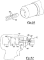
- the set of magnets 822" is mounted on a drive shaft 900 that receives rotary power directly from a motor 402c" that drives the transmission 404c".
- the drive shaft 900 extends through the transmission 404c" and into the chuck Cc" such that a distal end of the drive shaft 900 is mounted coaxially within the field winding 820" that is also housed in the chuck Cc".
- the set of magnets 822" can be mounted to the distal end of the drive shaft 900.
- the set of magnets 822" can comprise two or more magnets that can be spaced apart axially along a portion of the distal end of the drive shaft 900.
- the drive shaft 900"' is mounted to a component within the transmission 404c"' or that is driven by the transmission 404c"' so as to permit the drive shaft 900"' to rotate at a speed that is higher than the rotational speed of the output spindle 406c.
- the drive shaft 900"' is coupled for rotation with a planet carrier 910 associated with a second stage 912 of the transmission 404c"' that is intermediate input and output stages 914 and 916 of the transmission 404c"'.
Landscapes
- Engineering & Computer Science (AREA)
- Mechanical Engineering (AREA)
- Power Engineering (AREA)
- General Engineering & Computer Science (AREA)
- Life Sciences & Earth Sciences (AREA)
- Sustainable Development (AREA)
- Sustainable Energy (AREA)
- Physics & Mathematics (AREA)
- Optics & Photonics (AREA)
- Details Of Spanners, Wrenches, And Screw Drivers And Accessories (AREA)
- Non-Portable Lighting Devices Or Systems Thereof (AREA)
Description
- The present invention relates to a power tool with a light for illuminating a workpiece.
- Power tools are often used in a variety of conditions ranging from well-lit indoor work spaces to outside construction sites or other areas that are not always well-lit. Accordingly, it is desirable to provide a method or apparatus that permits a power tool to have a lighting feature that will illuminate the workpiece that is being machined or worked on by the power tool. Such a lighting feature will assist a user to be able to adequately see the workpiece or work area that is being worked on or machined by the power tool even in substandard light conditions.
-
US 2002/0172035 discloses a power tool with a lighting device mounted on its housing to illuminate the area around the tool bit and a portion of the workpiece that will be machined by the tool bit. An electric light of the lighting device may be connected to a power source circuit via an electric line that includes electric wires. In order to facilitate the wiring operation, a wire guide preferably supports or retains at least a portion of the electric line. -
US 5,793,130 discloses a miniature electric generator and lighting apparatus for use in a power-driven tool. The apparatus includes a rotor assembly having a permanent magnet, and a stator assembly within which the shaft and magnet are received. The stator assembly includes a pair of electrically conductive arms extending on opposite sides of the rotor, an electrically conductive shank connecting the arms together, and a winding of electrically conductive wire presenting a pair of opposed ends. A lamp is connected to the ends of the winding by a circuit so that it is powered upon rotation of the shaft. A housing assembly supports thestator assembly 24 on the output shaft of the tool, and is secured to the tool. -
DE 2362550 discloses a drill chuck which is driven via a shaft by an electric motor disposed in a handheld drill housing. A light source is disposed in the chuck displaced from the axis of the drill bit and focused on the workpiece adjacent the end of the drill bit by lenses. The light source is powered from batteries located in the handgrip and connected to the chuck via slip rings. In operation, the circle of light described by the focused light source on the workpiece may be aligned by eye with a scribed circle on the workpiece and inclination of the drill away from the vertical will be manifested by distortion of the circle of light. -
DE 3831344 discloses a power tool in accordance with the preamble of Claim 1 of the appendant claims. - Because power tools may be used in adverse environmental conditions, it is desirable to protect such a lighting feature from the adverse environmental conditions.
- In one aspect, the present invention provides a power tool according to Claim 1.
- In another aspect, the present invention provides a power tool according to Claim 9.
- Preferred, and other optional, features of the invention are described and defined in the dependent claims.
- Further areas of applicability will become apparent from the description provided herein. The description and specific examples in this summary are intended for purposes of illustration.
- The drawings described herein are for illustrative purposes only of selected embodiments and not all possible implementations.
-
FIG. 1 is a side view illustrating a power tool in accordance with an embodiment of the invention. -
FIG. 2 is a perspective view illustrating a front portion of a power tool in accordance with an embodiment of the invention. -
FIG. 3 is a perspective close-up view of the power tool ofFIG. 2 with the end effector removed in order to more distinctly show surrounding elements. -
FIG. 4 is a perspective view similar to that shown inFIG. 3 with a retaining ring removed in order to more clearly show surrounding elements. -
FIG. 5 is a perspective view of a wire guide and printed circuit board (PCB) having light emitting diode (LED) elements. -
FIG. 6 is a partial perspective view of a bottom portion of the wire guide and PCB. -
FIG. 7 is a perspective view of the PCB and wires with the wire guide removed. -
FIG. 8 is a partial perspective rear view of the wire guide, PCB, and wires. -
FIG. 9 is a partial exploded perspective view of the wire guide and a power tool having some elements removed to better show other elements. -
FIG. 10 is a partial perspective view of a wire guide, clutch adjusting nut, clutch spring, and clutch washer mounted on the wire guide. -
FIG. 11 is a partial perspective view of a power tool and clutch collar where the clutch collar is shown in a forward position to illustrate the clutch adjusting nut, clutch spring, and clutch washer mounted to the nose cone. -
FIG. 12 is a partial rear perspective view of the wire guide mounted on the clutch collar. -
FIG. 13 is a partial perspective view of the wire guide mounted onto the nose cone. -
FIG. 14 is a partial cutaway perspective view of a nose cone as well as other elements mounted to the nose cone. The end effector and power transmission elements are removed for clarity. -
FIG. 15 is a perspective rear view of a holder in accordance with another embodiment of the invention. -
FIG. 16 is a partial perspective view of a power tool equipped with a holder similar to that shown inFIG. 15 . -
FIG. 17 is a partial perspective view with part of the housing removed of a power tool equipped with a holder similar to that shown inFIG. 15 . -
FIG. 18 is a partial perspective view of a power tool with part of the housing removed to expose interior components. -
FIG. 19 is a partial perspective cut-away view of a power tool equipped with a holder similar to that shown inFIG. 15 . The cut-away view illustrates some of the internal components of the power tool. -
FIG. 20 is a perspective view of another power tool constructed in accordance with the teachings of the present disclosure. -
FIG. 21 is a longitudinal section view of a portion of the power tool ofFIG. 20 . -
FIG. 22 is a partially exploded perspective view of the power tool ofFIG. 20 . -
FIG. 23 is a rear elevation view of a portion of the power tool ofFIG. 20 , illustrating a portion of a light ring in more detail prior to the deformation of a plurality of tabs on a holder. -
FIG. 24 is an enlarged perspective view of a portion of the light ring illustrated inFIG. 23 . -
FIG. 25 is an enlarged perspective view of a portion of the light ring shown after the plurality of tabs on the holder have been deformed to retain a circuit board to the holder. -
FIG. 26 is a perspective view of a portion of the power tool ofFIG. 20 , illustrating a cover associated with a gear case. -
FIG. 27 is a perspective view of a portion of a power tool which does not form part of the invention. -
FIG. 28 is an exploded perspective view of a portion of the power tool ofFIG. 27 . -
FIG. 29 is a longitudinal cross-sectional view of a portion of the power tool ofFIG. 27 . -
FIG. 30 is a perspective, partially sectioned view of a portion of yet another power tool constructed in accordance with the teachings of the present disclosure. -
FIG. 31 is a perspective, partially sectioned view of a portion of the power tool ofFIG. 30 , illustrating an output spindle and a field winding in more detail. -
FIG. 32 is a perspective, partially sectioned view of a portion of the power tool ofFIG. 30 , illustrating a sun gear and a set of magnets in more detail. -
FIG. 33 is a perspective view of a portion of another power tool constructed in accordance with the teachings of the present disclosure. -
FIG. 34 is a schematic illustration of another power tool constructed in accordance with the teachings of the present disclosure. -
FIG. 35 is an enlarged portion ofFIG. 34 , illustrating the set of magnets and the field winding positioned within the chuck. -
FIG. 36 is a schematic illustration of an alternative manner of mounting the set of magnets to the drive shaft. -
FIG. 37 is a schematic illustration of another power tool constructed in accordance with the teachings of the present disclosure. - Corresponding reference numerals indicate corresponding parts throughout the several views of the drawings.
- The invention will now be described with reference to the drawing figures, in which like reference numerals refer to like parts throughout. An embodiment in accordance with the present invention provides a power tool having a light ring configured to shine light onto a workpiece being operated upon by the power tool.
- According to some embodiments of the invention, light emitting elements, such as light emitting diodes (LEDs), are placed in an annular or ring shape around part of the end effector and are configured to shine forward to illuminate the tool or accessory held by the end effector and the workpiece being machined by the tool. The end effector may be a tool or accessory holder mounted to an output spindle of the tool. Examples of end effectors that may be used in accordance with the invention may be the 7000 Series chuck manufactured and marketed by the Jacobs Chuck Manufacturing Company of Clemson, SC and quick change chucks and bit holders similar to those which are found on products such as a DC825KA Impact Driver and the driver that is disclosed in
U.S. Application Serial No. 12/394,426 and a DC815KA Impact Driver that are manufactured and marketed by the DeWalt Industrial Tool Company of Baltimore, MD. - While several different types of lighting elements can be used in accordance with the invention, such as light bulbs (for example, xenon bulbs) or other lighting elements, LED lights are discussed here as an example and do not limit embodiments in accordance with the invention to tools using LEDs. The LED lights, or other lighting elements, and associated parts are locked to the housing of the tool and do not rotate when the power tool is operated. The lights may be powered by the same power source that provides power to the power tool's motor. In the case of most cordless power tools, it is a battery that powers the power tool and in the case of corded tools it is AC current provided from source voltage through a cord. This AC current may be modified according to the needs of the lighting device being employed. In the case of LED lights, a rectifer may be employed to convert AC current to DC.
- An embodiment in accordance with the invention is illustrated in
FIG. 1. FIG. 1 shows apower driver 20. Thepower driver 20 has ahousing 22. The housing may be of a clam shell type or any other suitable type housing. Thepower driver 20 may have anose cone 23 located at the front portion of thepower driver 20. Ahandle 24 projects downwardly from thehousing 22 and is terminated with abattery 26. Thebattery 26 provides the power to turn theend effector 28. - The
end effector 28 may be configured to hold an accessory or tool such as a drill bit or a driving type accessory such as a Philips or standard screwdriver. Other types of tools or accessories may be held and used in theend effector 28 as can appreciated by one skilled in the art. The movement of theend effector 28 may be controlled by thetrigger 30. Thetrigger 30 may selectively provide power from thebattery 26 to themotor 32 located within thehousing 22. In some embodiments of the invention, the more the trigger or switch 30 is depressed the more power may be applied to themotor 32 which may cause theend effector 28 to spin faster. - The
power driver 20 may be equipped with aclutch collar 34. Other embodiments in accordance with the invention may not have a rotating clutch collar, but rather a different rotating collar mechanism. The rotating collar mechanism may be a drill/hammer mode selector, a gear shifter, an on/off switch, a tool variable speed control or other rotating collar control mechanism. However, this specification will refer to a clutch collar as an example but does not limit embodiments in accordance with the invention to tools having clutch collars. Theclutch collar 34 can provide protection for interior portions of thepower driver 20, particularly the transmission and other internal components of thepower driver 20 that may be mounted on thenose cone 23. Theclutch collar 34 may be rotated to adjust the transmission. An example of a clutch and transmission that may work in accordance with the invention is shown inU.S. Patent No. 7,066,691 . Of course, most any type of clutch and transmission may be used in accordance with the invention. Different angular positions of theclutch collar 34 may provide different amounts of torque and/or speed to theend effector 28 for a giventrigger 30 position. A numberedscale 36 may appear on theclutch collar 34 in order to provide a user an indication of the setting of theclutch collar 34. In some embodiments the user may turn theclutch collar 34 to a desired position by hand. - A
light ring 38 is located on a front portion of thepower tool 20 just behind theend effector 28 in arecess 39 in theclutch collar 34. - In
FIG. 2 , a partial perspective view of a front portion of thepower driver 20 is shown. Anindicator 37 may be located on thenose cone 23. Theindicator 37 may provide a reference for the user for determining the angular position of theclutch collar 34 and a reference point for comparing the numbers on the numberedscale 36. Thelight ring 38 is located within arecess 39 of theclutch collar 34. Thelight ring 38 may include acover 40. Thecover 40 may protect interior components of the tool from moisture or other contaminants. Thecover 40 may includeblisters 42 located on thecover 40 as to be directly over the LEDs 58 (as shown inFIG. 5 ). Theblisters 42 may be translucent or clear in order to permit light generated by theLEDs 58 to pass through. In some embodiments theblisters 42 may direct or focus the light. Theblisters 42 may be round, rectangular, square or any other shape. In some embodiments theblisters 42 are shaped to correspond with the shape of thelighting elements 58. In other embodiments the light may simply pass through theblisters 42. The remainder of thecover 40 may be a dark color. Other color schemes may be used in accordance with the invention. - The
cover 40 is held axially in place from moving in a forward direction toward theend effector 28 by retainingring 44. The retainingring 44 is mounted on aretainer 46 which is part of thenose cone 37 as better illustrated inFIGS. 13 and14 and described in more detail later below. -
FIG. 3 is a similar view to that shown inFIG. 2 , however, theend effector 28 is removed to better illustrate certain features associated with the retainingring 44 and theretainer 46.FIG. 3 showsportions 48 of the retainingring 44 exposed ingap 50 that would fit within thegroove 52 if it were not in thegap 50. The retainingring 44 fits within agroove 52 in theretainer 46. When the retainingring 44 is placed in thegroove 52 the retainingring 44 is secured in place. The retainingring 44 prevents thecover 40 from axially moving forward toward theend effector 28. -
FIG. 4 is a similar view as that shown inFIG. 3 , however, the retainingring 44 has been removed as well as theend effector 28 to better illustrate features of thecover 40 and theretainer 46. Thecover 40 includestabs 56, which are located within thegaps 50 of theretainer 46. Thetab 56 andgap 50 combination keep thecover 40 aligned and from rotating around theretainer 46. Thegroove 52 is also illustrated inFIG. 4 in which the retainingring 44 is located as shown inFIG. 3 . -
FIG. 5 illustrates other aspects of thelight ring 38, which are normally contained within theclutch collar 34 and located behind thecover 40. As part of thelight ring 38, light emitting diodes orLEDs 58 are located at various points around thelight ring 38. In some embodiments in accordance with the invention, theLEDs 58 emit white light although in other embodiments theLEDs 58 might emit other colors of light. In some embodiments different LEDs on the same tool could emit different colors of light. While the embodiment shown inFIG. 5 illustrates threeLEDs 58 any number of LEDs may be used in accordance with the invention including one or more. - The
LEDs 58 are mounted to a ring-shaped printed circuit board orPCB 60. ThePCB 60 andLEDs 58 are fit into atrench 61 in thewire way 62. Thewire way 62 andtrench 61 may allow for potting of the PCB if necessary. Thewire way 62 provides protection and structural strength for the PCB so that undue mechanical loads are not placed upon thePCB 60. Such support is desirable as aPCB 60 may be fragile and subject to breaking or malfunctioning. Thewire way 62 may include snap-infeatures 64 which allow thePCB 60 to be pushed into thewire way 62 and then the snap-infeatures 64 snap out once thePCB 60 is located within thewire way 62. The snap-infeatures 64 prevent thePCB 60 from coming out of thewire way 62. - The
wire way 62 may includegrooves 66.Tabs 68 located on thePCB 62 may fit within thegrooves 66 within thewire way 62. Thetabs 68 andgrooves 66 combination help thePCB 60 and thewire way 62 be aligned and may prevent or resist thePCB 60 from rotating with respect to thewire way 62. - The
wire way 62 may include aPCB holding portion 70 which is generally circular in shape and awire supporting portion 72. Thewire supporting portion 72 may include achannel 74 which is sized and located to containwires 76. Thewires 76 may provide power to thePCB 60 which in turns provides power to illuminate theLEDs 58. Thewire supporting portion 72 of thewire way 62 provides a structure for thewires 76 to be supported in and provides protection for thewires 76. Thewires 76 may terminate with aplug 78. Theplug 78 may fit intoplug supporting structure 80 located within thewire supporting portion 72 so that theplug 78, which is made of a more rigid material than thewires 76, is held securely to thewire way 62 via theplug supporting structure 80. In some embodiments, theplug 78 may be press fit into thewire supporting portion 72 of thewire way 62. The circuit to which thePCB 60 is connected may also include an electromagnetic surge suppression circuit (such as a zener diode) for static and over-voltage protection. The circuit may also include a resistor or resistors to drop the voltage from the battery pack voltage to an appropriate level for the LEDs. - Some embodiments do not have a separate PCB, wire guide, wires and connector. For example, plated plastics can be used whereby the wire guide could be first molded into a shape similar to the
wire guide 62 as shown. Secondly, tracks (like on a standard PCB) could be created on this plastic piece, and could include all of the pads to mount LEDs and other components, the tracks, or "wires," from the front of the tool back to the connector area, and could even include the male end of the connector. The components (diodes, resistors, etc.) could then be soldered to this one piece, and would be electrically connected back to the place where the wires would connect it to the switch. This would greatly simplify the assembly. -
FIG. 6 is a partial perspective view of a bottom portion of thewire way 62. Thewire way 62 may be equipped with acollar stopping tab 82 which will be explained in more detail below asFIG. 12 is discussed. -
FIG. 7 is a perspective view similar to that shown inFIG. 5 , however, thewire way 62 has been removed in order to better illustrate some of the features shown inFIG. 7 . TheLEDs 58 are mounted onto thePCB 60. ThePCB 60 shows thetabs 68. While the embodiments shown in the figures show fivetabs 68, one skilled in the art can appreciate that other numbers of tabs or other features may be employed in order to help keep the PCB aligned and/or rotationally locked to thewire way 68. - The
wires 76 are attached to a rear portion of thePCB 60. Theplug 78 includes theplug stopping structure 84 which butts against a portion of thewire way 68 to prevent theplug 78 from being inserted too far into thewire way 62. -
FIG. 8 illustrates theplug stopping structure 84 located on theplug 78 butted against thewire supporting portion 72 of thewire way 62. Thewires 76 are located within thechannel 74. In some embodiments, theplug 78 snaps into thewire supporting portion 72 and thewires 76 may be pressed into thechannel 74 in a press fit manner to secure thewires 76 into thechannel 74. A rear portion of thecollar stopping tab 82 is also illustrated inFIG. 8 . -
FIG. 9 illustrates thehousing 22 and thewire way 62. Thenose cone 23 has been removed in order to better illustrate how theplug 78 attaches to a receivingplug 86. Theplug 78 is slid into the receivingplug 76. Theplug stopping structure 84 slides intoslots 87 located on the receivingplug 86. Once theplug 78 and the receivingplug 86 have been mated together, power from thewires 88 is communicated to thewire 76. The joint made of theplug 78 and the receivingplug 86 provide a rigid support for the connection of thewires wires 88 may receive power from thebattery 26 as controlled by thetrigger 30. In some embodiments thewires 88 extend out of a switch body associated with thetrigger 30. In other embodiments, a switch body could have connectors to which thewires 88 are soldered or otherwise connected. The trigger switch may include electronics for variable speed control. Thewires 88 may be soldered to a PCB located inside the switch body. - In accordance with some embodiments of the invention, when the
trigger 30, as shown inFIG. 1 , is depressed, power is sent to thewires 88 and inturn 76 to illuminate the LEDs. -
FIG. 10 is a partial perspective view of theguide 62 showing several additional elements on theguide 62. Aclutch adjusting nut 90 is butted against theguide 62. Thestop tab 82 is fit into anotch 92 in theclutch adjusting nut 90. Thenotch 92 in theclutch adjusting nut 90 aligns to the stoppingtab 82 on theguide 62 to assist in providing proper assembly of the threads between the adjustingnut 90 and thenose cone 23 during assembly. In some embodiments and as shown inFIG. 10 , thenotch 92 and theclutch adjusting nut 90 may have chamferededges 96 to thenotch walls 94. The chamfered edges 96 may assist in the stoppingtab 82 to be seated in thenotch 92 and theclutch adjusting nut 90. - According to some embodiments, a combination of the
notch 92 and theclutch adjusting nut 70 and the stoppingtab 82 in combination with the other tabs and notchcombinations cover 40, thenose cone 23, thewire way 62, thePCB 60, and theclutch adjusting nut 90 are aligned with respect to each other. - The
clutch adjusting nut 90 includes aridge 100. As shown inFIG. 10 aclutch spring 102 urges at one end against theridge 100 and at the opposite end of theclutch spring 102, theclutch spring 102 urges against aclutch washer 104. Theclutch spring 102 exerts a force on theridge 100 of theclutch adjusting nut 90 which in turn urges thewire way 62 against thecover 40 and ultimately against the retainingring 44. The force exerted by theclutch spring 102 keeps thelight ring assembly 38 in axial position. As shown inFIG. 11 theclutch washer 104 urges against thenose cone 23. -
FIG. 11 illustrates theclutch washer 104,clutch spring 102, and theclutch adjusting nut 90 mounted to thenose cone 23. Theclutch collar 34 is shown in a forward axial position and not yet installed on thepower tool 20 in order to expose theclutch washer 104, theclutch spring 102 and theclutch adjusting nut 90. - To provide ease in the assembly of the
power tool 20, atab 98 on theclutch adjusting nut 90 is scored with marks ornotches 106 on one of theadjustment tabs 98. The scoring 106 provides a visual aid when assembling thecollar 34 to properly align theclutch collar 34. Theadjustment tab 98 on theclutch adjusting nut 90 is aligned with a desirednotch 108 in theclutch collar 34. Once the desirednotch 108 is aligned with the desiredadjustment tab 98, theclutch collar 34 can be fitted onto thepower tool 20. In some embodiments, theindicator 34 and the numberedscale 36 may also provide assistance in aligning theclutch collar 34 to provide proper assembly of theclutch collar 34 onto thenose cone 23. -
FIG. 12 is a partial perspective view of theclutch collar 34 installed onto theguide 62. Other elements have been omitted fromFIG. 12 in order to better show the interaction between theguide 62 and theclutch collar 34. Theclutch collar 34, in some embodiments in accordance with the invention, is rotatable. Theclutch collar 34 is rotatable on thepower tool 20 in order to provide different torque and/or speed settings for theend effector 28. It may be desirable to limit the rotation of theclutch collar 34 in both directions to establish a maximum setting for turning the clutch collar clockwise and a maximum setting when turning the clutch collar counterclockwise as shown inFIG. 12 . Making maximum and minimum settings is, in some embodiments, accomplished by using thecollar stopping tab 82 which butts against thestop 110 on theclutch collar 34. Thewall 112 on thestop 110 butts against awall 114 on thecollar stopping tab 82 to provide a limit toclutch collar 34 rotation in a clockwise direction as viewed inFIG. 12 . Thesame stop 110 andcollar stopping tab 82 provide a stop for rotating theclutch collar 34 in the opposite direction (i.e., counterclockwise as viewed inFIG. 12 ). This is accomplished when theclutch collar 34 is rotated so that theopposite wall 116 on thestop 110 butts against theopposite wall 118 on thetab 82. -
FIG. 12 also illustratesadditional notches 108 in theclutch collar 34 for providing detents when theclutch collar 34 is rotated to various settings with respect to thenose cone 23. -
FIG. 13 is a partial perspective view of theguide 62 mounted onto astem portion 120 of thenose cone 23. Alock portion 124 of theguide 62 fits into agroove 122 of thestem portion 120 of thenose cone 23. Thegroove 122 is sized and dimensioned so that thelock portion 124 of thewire supporting portion 72 of theguide 62 fits within thegroove 122 and locks theguide 62 to be angularly fixed with respect to thenose cone 23. Thelocks 124 located on thewire supporting portion 72 of theguide 62 are wider than the rest of thewire supporting portion 72 and aid in permitting theguide 62 to be securely seated in thegroove 122 of thestem portion 120 of thenose cone 23. - A
second groove 126 is in thenose cone 23 for allowing thewire supporting portion 72 of theguide 62 to fit within thegroove 126 of thenose cone 23. Theretainer 46 on thenose cone 23 and thegroove 52 of thenose cone 23 are also shown forward of theguide 62. The above described features also help align theguide 62 with respect to thenose cone 23. - According to some embodiments, the
retainer 46 is integral with thestem 120 and thenose cone 23. In other embodiments of the inventions, they may be separable parts. -
FIG. 14 is a partial cutaway perspective view of thenose cone 23 and additional parts described below.FIG. 14 shows how the parts described herein are assembled together according to some embodiments of the invention. The transmission, spindle, and other parts associated with turning the end effector have been omitted to more clearly show the parts described herein. The retainingring 44 is seated within thegroove 52 of theretainer 46. The retainingring 44 provides a limit of forward axial movement of thecover 40, theguide 62, and theclutch adjusting nut 90. Theclutch spring 102 presses against theclutch washer 104 to urge theclutch adjusting nut 90 to urge theguide 62,PCB 60, and cover 40 against the retainingring 44. Thewires 76 are located in achannel 74 defined by theguide 62 and thenose cone 23. Thewires 76 are protected from the spinning parts of the end effector mechanism. - Although an example of the
light ring 38 is shown on apower driver 20, it will be appreciated that thelight ring 38 can be used on other rotary power tools such as impact drivers, drills, hammer drills, routers. - An example embodiment in accordance with the invention where a
light ring 38 is mounted on a different power tool than shown in the previous FIGS. is shown inFIGS. 15 through 19 .FIG. 15 illustrates a perspective rear view of aholder 140 that is used on a power tool that is not equipped with a collar as described in the embodiments above. Theholder 140 holds thelight ring 38. Thelight ring 38 includes thePCB 60 similar to that described above. ThePCB 60 and theholder 140 may include snap-infeatures 64 similar to that described above so that thePCB 60 snaps into and is secured in theholder 140. - A
circular cover 40 may be mounted to theholder 140 in front of thePCB 60 similar to embodiments described above. Thecover 40 may include snap-in elements that correspond with snap-in elements on theholder 140. In other embodiments in accordance with the invention, thelens 40 may be secured in place with a retaining ring system similar to that described above. - The
holder 140 may attach to thenose cone 23 with snap-in elements located on both theholder 140 and thenose ring 23 similar to the snap-infeatures 64 described in the embodiments above. In other embodiments in accordance with the invention, thelight ring holder 140 may be secured in place in a variety of ways including, but not limited to, a retaining ring system similar to the embodiments described above. - As shown in
FIG. 15 , theholder 140 includes ahousing portion 142, achin shroud 144, and awire way portion 146.Wires 76 connect the PCB 60 (which contains light emitting elements similar to those described above) with aplug 78. In contrast to thewire way 62 described in the embodiments above, theholder 140 does not fully support thewires 76 along the full length of thewires 76 all the way to theplug 78. Rather, thewire way portion 146 stops at some point along the length of thewires 76, leaving thewires 76 and theplug 78 to be not supported by theholder 140. -
FIG. 16 is a partial perspective view of apower tool 147 that does not have a rotatable clutch collar but rather is equipped with theholder 140. Thecover 40 is shown mounted in a recess in theholder 140. Theholder 140 is mounted to thenose cone 23 which is supported by thehousing 22. Afastener hole 148 is shown in thehousing 22. Thefastener hole 148 provides a place for a fastener such as a screw or bolt to connect the two halves of the clamshell type housing 22 together. While the fastener is not shown inFIG. 16 , it will be appreciated that when thepower tool 147 is fully constructed that a fastener will be located in thefastener hole 148 to connect the two halves of theclam shell housing 22 together. Other embodiments of the invention may connect the clamshells of thehousing 22 in other ways. Some embodiments of the invention may include one piece housings or other types of housings than the clam shell housing shown inFIG. 16 . Thechin shroud 144 is located on theholder 140 and provides a housing for a portion of thewires 76 so that thewires 76 are not exposed outside of thepower tool 147. -
FIGS. 17 and 18 show thepower tool 147 with part of thehousing 22 removed. Thehousing 22 is a clam shell type housing and one of the clam shells is removed exposing theclam shell housing 22 located on the far side of thepower tool 147. Theholder 140 is shown mounted to thenose cone 23. Afastener hole tube 150 located in thefastener hole 148 is shown. Thewires 76 are routed around thehole tube 150 and are located in theinterior 152 of thehousing 22. Thewires 76 are terminated with aplug 78 also located in theinterior 152 of thehousing 22. - The
interior 152 of the housing defines a space or pathway for thewires 76 and theplug 78. Thechin shroud 144 defines awire way portion 146 through which thewires 76 are strung. Thechin shroud 144 also includes retainingstructure 154 which is set in a retainingarea 156 defined by thehousing 22. When the two clam shells of theclam shell housing 22 are mounted together and fastened together with a fastener located in thefastener hole 148 andfastener hole tube 150, the retainingstructure 154 on thechin shroud 144 is trapped in the retainingarea 156 thereby holding thechin shroud 144 andholder 140 in place on thepower tool 147. Operation of thelight ring 38 is similar to that described in the embodiments above. -
FIG. 19 is a partial perspective cut-away view showing theend effector 28 associated with thepower tool 147 extending through thecover 40 located in front of thePCB 60. As described above, LEDs (not shown inFIG. 19 ) are located on thePCB 60 and configured to light the tool or workpiece being worked on by thepower tool 147. Thewires 76 provide power between thePCB 60 and a power source connected via theplug 78 to power source. Thewires 76 are located in thewire way portion 146 of thechin shroud 144 and theinterior 152 of thehousing 22. Thechin shroud 144 has the retainingstructure 154 located in the retainingarea 156 defined by thehousing 22. - While the driver 20 (
Fig. 1 ) has been illustrated and described herein as including a lighting system that is disposed between a gear case and a rotating collar 34 (Fig. 1 ) of the driver 20 (Fig. 1 ) and/or forwardly of a housing 22 (Fig. 1 ) and/or a gear case or nose cone 23 (Fig. 1 ), it will be appreciated that the driver could be constructed somewhat differently. With reference toFigures 20 through 22 , for example, another driver constructed in accordance with the teachings of the present disclosure is generally indicated byreference numeral 400. Thedriver 400 can include ahousing assembly 22a, amotor 402, atransmission 404, anoutput spindle 406, abattery pack 408 and alighting system 410. In the particular example provided, thedriver 400 is depicted as being an impact driver that operates theoutput spindle 406 in a rotary manner similar to that which is disclosed inU.S. Application Serial No. 12/769,981 . Those of skill in the art will appreciate that thedriver 400 could be configured as a screwdriver, drill driver, hammer drill driver, and/or rotary hammer to provide a rotary and/or axial output or could be configured to provide an axial output (e.g., hammer). - The
housing assembly 22a can be configured to house themotor 402, thetransmission 404 and at least a portion of theoutput spindle 406. In the example provided, thehousing assembly 22a includes aclam shell housing 416, which is formed by a pair of clam shell halves, and agear case assembly 418 that includes a firstgear case member 420, a secondgear case member 422, and acover 424. - The first
gear case member 420 can define afirst case portion 430 and asecond case portion 432. Thefirst case portion 430 can be mounted to theclam shell housing 416 and extend forwardly therefrom. Thefirst case portion 430 can define aninternal cavity 436 into which thetransmission 404 can be received. Thesecond case portion 432 can be coupled to or integrally formed with thefirst case portion 430 and can extend forwardly therefrom. Thesecond case portion 432 can define aspindle aperture 440 and a mounting boss 442. Thespindle aperture 440 can intersect theinternal cavity 436 to define a passageway through which the output spindle can be received. - The second
gear case member 422 can define abearing mount 450 and one or more through-holes 452. Thebearing mount 450 can be configured to receive a spindle support bearing 454 therein. The secondgear case member 422 can be received on the mounting boss 442 and can be secured thereto via a plurality offasteners 456. It will be appreciated that the mounting boss 442 is configured to align the spindle support bearing 454 to therotational axis 460 of theoutput spindle 406. - The
motor 402, thebattery pack 408 and thetransmission 404 can be conventional in their construction and operation. Briefly, themotor 402 can be housed in theclam shell housing 416 and can be electrically coupled to thebattery pack 408 through a trigger (switch) 30a. Thebattery pack 408 can be releasably coupled to theclam shell housing 416. Thetransmission 404 can be any type of transmission, such as a multi-stage planetary transmission, and can have an input member, that can be driven by anoutput shaft 464 of themotor 402, and an output member that can be drivingly coupled to theoutput spindle 406. In the particular example provided, thetransmission 404 includes a single stageplanetary reduction 470 and a Potts-type impact mechanism 472. Asun gear 474 associated with theplanetary reduction 470 serves as the transmission input, while aplanet carrier 476 associated with the planetary reduction serves as an output of theplanetary reduction 470. Theimpact mechanism 472 can include aninput spindle 480, which can receive rotary power from theplanet carrier 476, ahammer 482, which can be mounted on theinput spindle 480, a cam mechanism (not specifically shown), animpact spring 486 and ananvil 488. The cam mechanism can couple thehammer 482 to theinput spindle 480 in a manner that permits limited rotational and axial movement of thehammer 482 relative to theinput spindle 480. Theimpact spring 486 can bias thehammer 482 into a position where the cam mechanism rotatably couples thehammer 482 to theinput spindle 480. Theanvil 488, which can be mounted for rotation on theinput spindle 480, is configured to engage thehammer 482 such that rotational energy in thehammer 482 can be transmitted to theanvil 488. - The
output spindle 406 can be integrally formed with theanvil 488 and can have ashaft member 490, achuck portion 492, and ajournal portion 494 that can be disposed on a side of thechuck portion 492 opposite theshaft member 490. Theshaft member 490 can be supported for rotation about therotational axis 460 by abushing 500 that is disposed in thefirst case portion 430 of the firstgear case member 420. Thechuck portion 492 can be disposed forwardly of the firstgear case member 420 and can be configured to receive a tool bit, such as a ¼ inch hex bit, therein. Thejournal portion 494 can be a distal end of theoutput spindle 406 and can be received in the spindle support bearing 454 in the secondgear case member 422 such that the end of theoutput spindle 406 opposite theinput spindle 480 is journally supported by the secondgear case member 422. - The
lighting system 410 can include alight ring 38a and acircuit assembly 510. - The
light ring 38a can comprise aholder 140a and awireway 62a. Theholder 140a can be formed in a generally semi-annular (e.g., horseshoe) shape that is configured to be mounted about a portion of the mechanism that unlatches the chuck or bit holder, as well as be matingly received on the mounting boss 442 of the firstgear case member 420 such that thelight ring 38a is rotationally fixed to thehousing assembly 22a. Theholder 140b can define atrench 61a, which can be configured to receive thecircuit assembly 510, and a plurality ofLED apertures 520 that can extend axially through theholder 140a in-line with the through-holes 452 in the secondgear case member 422. Thewireway 62a can define awire channel 524, as well as anoperator mount 526 that can be configured to receive there through an axiallymovable button 528 that can be employed to unlatch the bit holder C. Thebutton 528 can be coupled to alever 530, which is fitted to abit holder sleeve 532, and can be biased outwardly from theclam shell housing 416 via abutton spring 534. Thebit holder sleeve 532 can be axially movably mounted on thechuck portion 492 of theoutput spindle 406 between a first or latched position, in which alocking ball 538 is urged radially inwardly into the hollow interior of thechuck portion 492, and a second or unlatched position in which thelocking ball 538 may be moved radially outwardly so that a tool bit received in thechuck portion 492 can be withdrawn from theoutput spindle 406. Thewireway 62a can effectively close an opening about thebutton 528 between thegear case assembly 418 and theclam shell housing 416. - The
circuit assembly 510 can include acircuit board 60a, a plurality of LED's 58a and awire harness 550. Thecircuit board 60a can be formed of an insulating material and can include wires or conductors (not specifically shown) that can electrically couple thewire harness 550 and the LED's 58a. In the particular example provided, thecircuit board 60a is a printed circuit board that is formed in a semi-annular shape that is configured to be received in the correspondingly shapedtrench 61a formed in thelight ring 38a. The LED's 58a can be fixedly coupled to thecircuit board 60a and can be disposed in-line with theLED apertures 520 formed in thelight ring 38a. If desired, the LED's 58a can extend into or through theLED apertures 520. Thewire harness 550 can comprise a plurality of wires 76a and aplug 78a. The wires 76a can include first and second wires (not specifically shown) that can be coupled to the conductors of thecircuit board 60a and to the conductors (not specifically shown) in theplug 78a to transmit electrical power between theplug 78a and the LED's 58a. The wires 76a can be received in thewireway 62a in thelight ring 38a and can be festooned or routed through awire channel 524 formed in theclam shell housing 416. Theplug 78a can be configured to matingly engage a corresponding plug (not specifically shown) to electrically couple thecircuit assembly 510 to a source of electrical power. In the particular example provided, the corresponding plug is electrically coupled to atrigger 30a that is coupled to thebattery pack 408. Thetrigger 30a can be configured to transmit electrical power from thebattery pack 408 to thecircuit assembly 510 in a desired manner, such as during operation of themotor 402, or during operation of themotor 402, as well as for a predetermined amount of time after operation of themotor 402. - The
circuit assembly 510 can be coupled to thelight ring 38a in any desired manner, including adhesives, potting compounds, clips and fasteners. In the particular example provided, thelight ring 38a comprises a plurality of retainingtabs 560 that can extend throughtab apertures 562 in thecircuit board 60a. With additional reference toFigures 23 and 24 , thetabs 560 can be initially formed to extend in an axial direction that is generally parallel to therotational axis 460 of theoutput spindle 406, which can facilitate the axial translation of thecircuit board 60a into thetrench 61a, and can be deformed in whole or in part to retain thecircuit board 60a within thetrench 61a. Thetabs 560 can be deformed by twisting or bending, but in the example provided, each of thetabs 560 is heated and bent over at a right angle as shown inFigure 25 so as to lie over a portion of thecircuit board 60a adjacent a corresponding one of the tab apertures 562. - With renewed reference to
Figures 20 through 22 and additional reference toFigure 26 , thecover 424 can be fixedly coupled to the secondgear case member 422 in any desired manner, such as via mating sets of ribs andgrooves 590. It will be appreciated that mating features (not specifically shown) may be formed into thecover 424 and the secondgear case member 422 that inhibit rotation of thecover 424 relative to the secondgear case member 422 when thecover 424 is engaged to the secondgear case member 422. Thecover 424 can define a set of second through-holes 592, as well as abutton stop 594. The set of second through-holes 592 can be disposed in-line with the through-holes 452 in the secondgear case member 422 and the LED's 58a in thecircuit assembly 510 such that light generated by the LED's 58a can be transmitted through the secondgear case member 422 and thecover 424 to illuminate an area forwardly of thegear case assembly 418 and theoutput spindle 406. Thebutton stop 594 can be disposed forwardly of thebutton 528 and can be employed to limit forward axial movement of thebutton 528. - It will be appreciated that if desired, various devices (not shown), such as lenses and/or diffusers, may be incorporated into the
driver 400. For example, such devices may be located in one or both of the through-holes 452 in the secondgear case member 422 and the second through-holes 592 in thecover 424. - If desired, one or more resilient elements may be disposed between the
light ring 38a and thegear case assembly 418 to generate or limit an axially directed clamping force that is exerted onto thelight ring 38a. In the particular example provided, four resilient dampers 598 are mounted to secondgear case member 422 and abut the front axial face of thelight ring 38a. The resilient dampers 598 are compressed when the secondgear case member 422 is fastened to the firstgear case member 420 to thereby apply a clamping force to thelight ring 38a that inhibits movement of thelight ring 38a relative to thegear case assembly 418. - With reference to
Figures 27 through 29 , a driver which does not form part of the invention is generally indicated byreference numeral 600. Thedriver 600 can be a drill/driver of the type that is disclosed inU.S. Patent Application Serial No. 12/610,762 , except that a lighting system is incorporated into thedriver 600. In the example provided, thelighting system 410b includes afirst portion 610, which can be mounted to anoutput spindle assembly 611, and asecond portion 612 that can be coupled for rotation with a drill chuck Cb. - The
first portion 610 can comprise a set ofspring contacts 620 that can be electrically coupled to a source of electrical power (e.g., to a battery pack via a trigger switch). Thespring contacts 620 can comprise afirst spring contact 620a and asecond spring contact 620b that can be electrically isolated from one another. Thefirst spring contact 620a can be offset in a radial direction by a first distance from arotational axis 460b of the output spindle 406b, while thesecond spring contact 620b can be offset in a radial direction by a second distance that is different from the first distance. - The
second portion 612 can comprise asleeve 630, acoupler 632, abushing 634, aholder 140b, acircuit assembly 510b, acover 636 and a retainingring 638. Thesleeve 630 can be received about the chuck Cb and can be configured to receive a rotary input from an operator to open or close the jaws (not shown) of the chuck Cb. It will be appreciated that the chuck Cb can be any type of chuck Cb, such as a keyless chuck. - The
coupler 632 can include anannular plate 640, first and second conductor tracks 642 and 644, respectively, and aplug 78b. Theannular plate 640 can be formed of an electrically insulating material, such as a durable relatively nonconductive plastic (i.e., a plastic that is electrically insulating when an electrical potential that is less than 50 or 100 volts is applied to it). Theannular plate 640 can be fixedly mounted on thespindle 650 of the chuck Cb. Thespindle 650 of the chuck Cb can be engaged to the output spindle 406b by any desired means. In the particular example provided, thespindle 650 of the chuck Cb is threaded onto the output spindle 406b via left-handed threads and aspindle retaining fastener 652 is fitted through thespindle 650 and threadably engaged to the output spindle 406b. Accordingly, it will be appreciated that as thespindle 650 of the chuck Cb is coupled for rotation with the output spindle 406b, theannular plate 640 will also rotate with the output spindle 406b by virtue of its connection to thespindle 650 of the chuck Cb. The first and second conductor tracks 642 and 644 can be mounted to a first side of theannular plate 640 and can be disposed concentrically such that they are electrically isolated from one another. The first and second conductor tracks 642 and 644 can be configured to electrically engage the first andsecond spring contacts plug 78b can be fixedly coupled to a second side of theannular plate 640 and can comprise terminals (not specifically shown) that can be electrically coupled to the first and second conductor tracks 642 and 644. In the particular example provided, the terminals extend through theannular plate 640 so as to intersect respective portions of the first and second conductor tracks 642 and 644 and solder is employed to electrically couple the terminals and the first and second conductor tracks 642 and 644. - The
bushing 634 can be received between thespindle 650 of the chuck Cb and thesleeve 630 on a side of the chuck Cb opposite theannular plate 640. A slot or groove 656 can be formed in thebushing 634. - The
holder 140b can be an annular structure that can define anannular trench 61b. - The
circuit assembly 510b can include acircuit board 60b, a plurality of LED's 58b and awire harness 550b. Thecircuit board 60b can be formed of an insulating material and can include wires or conductors (not specifically shown) that can electrically couple thewire harness 550b and the LED's 58b. In the particular example provided, thecircuit board 60b is a printed circuit board that is formed in an annular shape that is configured to be received in the correspondingly shapedtrench 61b formed in theholder 140b. The LED's 58b can be fixedly coupled to thecircuit board 60b on a side opposite theholder 140b. Thewire harness 550b can comprise a plurality of wires 76b including first and second wires (not specifically shown) that can be coupled to the conductors of thecircuit board 60b and to the conductors (not specifically shown) in theplug 78b to transmit electrical power between theplug 78b and the LED's 58b. The wires 76b can be received in the radial space between thespindle 650 of the chuck Cb and thesleeve 630 and can extend longitudinally through thegroove 656 in thebushing 634. - The
circuit assembly 510b can be coupled to theholder 140b in any desired manner, including adhesives, potting compounds, clips and fasteners. In the particular example provided, theholder 140b comprises a plurality of retainingtabs 560b that can extend through tab apertures (not specifically shown) in thecircuit board 60b. Thetabs 560b can be initially formed to extend in an axial direction that is generally parallel to therotational axis 460b of thespindle 650 of the chuck Cb, which can facilitate the axial translation of thecircuit board 60b into thetrench 61b, and can be deformed in whole or in part to retain thecircuit board 60b within thetrench 61b. Thetabs 560b can be deformed by twisting or bending, but in the example provided, each of thetabs 560b is heated and bent over at a right angle so as to lie over a portion of thecircuit board 60b adjacent a corresponding one of the tab apertures. - The
cover 636 can be an annular structure that can be fitted to an axial end of thesleeve 630 opposite thecoupler 632 and can aid in axially fixing theholder 140b in place in thesleeve 630 against a front face of thebushing 634. Thecover 636 can be formed of a transparent material that can be clear or colored. The transparent material can be formed such that light received from the LED's 58b will exit thecover 636 in a desired manner. For example, the light exiting thecover 636 can be spread or concentrated over a desired area to illuminate one or more relatively large areas and/or one or more relatively small points. - The retaining
ring 638 can be received in aring groove 680 in thespindle 650 of the chuck Cb and can be configured to limit forward motion of thecover 636 relative to thesleeve 630 to thereby maintain thecover 636 on thespindle 650 of the chuck Cb. - With reference to
Figures 30 through 32 , another driver constructed in accordance with the teachings of the present disclosure is generally indicated byreference numeral 800. Thedriver 800 can be a drill driver of the type that is disclosed inU.S. Pat. No. 12/610,762 lighting system 410c includes agenerator 810, aconductive connector 812, anenergy storage device 814 and acircuit assembly 510c. - The
generator 810 can comprise one ormore field windings 820 and one or more sets ofmagnets 822. The field winding(s) 820 can be mounted on agenerator shaft portion 826 of theoutput spindle 406c of thedriver 800. As will be appreciated from the aforementioned '762 patent application, theoutput spindle 406c can be coupled (e.g., via a spindle lock) to an output member of anoutput stage 830 of a multi-stageplanetary transmission 404c. Thegenerator shaft portion 826 of theoutput spindle 406c in this example can extend rearwardly of theoutput stage 830 to orient each field winding 820 with a component within thetransmission 404c or driven by thetransmission 404c that is configured to rotate at a speed that is higher than the rotational speed at which theoutput spindle 406c is driven. In the example provided, thegenerator shaft portion 826 extends rearwardly into asun gear 832 that provides a rotary input to theoutput stage 830 of thetransmission 404c. Each set ofmagnets 822 can be mounted to a rotating element of thetransmission 404c (or an element rotated by thetransmission 404c) and can be arranged concentrically about an associated field winding 820. In the particular example provided, the set ofmagnets 822 is fixedly coupled to thesun gear 832 of theoutput stage 830 of thetransmission 404c. It will be appreciated that during operation of thedriver 800, each set ofmagnets 822 will rotate at a speed that is higher than the rotational speed of its associated field winding 820 and that as a result of the speed differential, an electric current will be induced in the field winding(s) 820. Stated another way, each set ofmagnets 822 and its associated field winding 820 comprise a generator that generates an electric current when rotary power is input to thetransmission 404c during operation of thedriver 800. - The
conductive connector 812 can be configured to electrically couple thegenerator 810 to theenergy storage device 814 and/or to thecircuit assembly 510c. In the example provided, theoutput spindle 406c has a hollow longitudinally-extendingcavity 840 into which theconductive connector 812 is received. Theconductive connector 812 can comprise a pair of wires that can be received through thecavity 840 such that theconductive connector 812 is mounted coaxially within theoutput spindle 406c. - The
energy storage device 814 can be electrically coupled thegenerator 810 and thecircuit assembly 510c in any desired manner and can be any type of energy storage device, including a rechargeable battery. In the particular example provided, theenergy storage device 814 is a capacitor that is mounted in a chuck Cc that is coupled to theoutput spindle 406c for rotation therewith. It will be appreciated, however, that theenergy storage device 814 could be mounted within theoutput spindle 406c in the alternative. - The
circuit assembly 510c can be electrically coupled to thegenerator 810 and/or to the energy storage device 814 (e.g., via the conductive connector 812) and can be mounted within the chuck Cc. Thecircuit assembly 510c can comprise one or more LED's 58c that can be driven by the electrical energy generated by thegenerator 810. - While the
generator 810 has been illustrated and described as including one or more field windings that mounted on an output spindle of a tool, it will be appreciated that the generator could be constructed somewhat differently. For example, the set of magnets 822' can be mounted to aplanet carrier 880 of a firstplanetary stage 882 while the field windings 820' can be mounted to aplanet carrier 884 of a secondplanetary stage 886 as shown inFigure 33 such that the set of magnets 822' rotate at a rotational speed that is higher than a rotational speed at which the field windings 820' rotate. - In the examples of
Figures 34 through 37 , the set of magnets is received within the field winding. InFigures 34 and 35 , the set ofmagnets 822" is mounted on adrive shaft 900 that receives rotary power directly from amotor 402c" that drives thetransmission 404c". Thedrive shaft 900 extends through thetransmission 404c" and into the chuck Cc" such that a distal end of thedrive shaft 900 is mounted coaxially within the field winding 820" that is also housed in the chuck Cc". The set ofmagnets 822" can be mounted to the distal end of thedrive shaft 900. With reference toFigures 35 and36 , the set ofmagnets 822" can comprise two or more magnets that can be spaced apart axially along a portion of the distal end of thedrive shaft 900. InFigure 37 , thedrive shaft 900"' is mounted to a component within thetransmission 404c"' or that is driven by thetransmission 404c"' so as to permit thedrive shaft 900"' to rotate at a speed that is higher than the rotational speed of theoutput spindle 406c. In the example illustrated, thedrive shaft 900"' is coupled for rotation with aplanet carrier 910 associated with asecond stage 912 of thetransmission 404c"' that is intermediate input andoutput stages transmission 404c"'. - The foregoing description of the embodiments has been provided for purposes of illustration and description. It is not intended to be exhaustive. Individual elements or features of a particular embodiment are generally not limited to that particular embodiment, but, where applicable, are interchangeable and can be used in a selected embodiment, even if not specifically shown or described.
Claims (12)
- A power tool comprising:a housing assembly (22a) having a housing structure (416) and a case (418) that is coupled to the housing structure, the case comprising a first case member (420) and a second case member (422);an output spindle (406) at least partially received in the case (418);a first bearing mounted to the first case member (420), the first bearing being configured to support a first axial end of the output spindle (406);a motor (402) housed in the housing assembly (22a) and providing a source of rotary power;a transmission (404) housed in the housing assembly and drivingly coupling the motor (402) to the output spindle (406); anda light system (410) comprising a light ring (38a) and a circuit assembly (510), the circuit assembly comprising a light emitting element (58a) and being received in the light ring, the light ring being received axially between the first (420) and second (422) case members;characterized in that: a second bearing (454) is mounted to the second case member (422), the second bearing being configured to support a second, opposite axial end of the output spindle (406); andthe circuit assembly (510) includes a circuit board (60a) that is fixedly coupled to the light ring (38a).
- The power tool of Claim 1, wherein the transmission (404) comprises a gear reduction; and/or wherein the transmission (404) comprises a rotary impact mechanism.
- The power tool of one of Claim 1 or Claim 2, wherein the second case member (422) comprises a through-hole (452) that is disposed in-line with the light emitting element (58a); and/or wherein the light ring (38a) forms a portion of an exterior surface of the power tool.
- The power tool of one of Claims 1 - 3, further comprising a resilient element (598) disposed between the light ring (38a) and the case (418), the resilient element exerting a clamping force onto the light ring to inhibit axial movement of the light ring relative to the case.
- The power tool of any preceding claim, further comprising a cover (424) that is coupled to the second case member (422) on a side opposite the first case member (420).
- The power tool of any preceding claim, wherein the light ring (38a) comprises a holder into which the circuit board (60a) is received, preferably wherein the holder comprises tabs (560) that are deformed to fixedly couple the circuit board to the holder.
- The power tool of Claim 6, wherein the light ring (38a) comprises a wireway (62a) for receipt of a wire harness (550) that is electrically coupled to the circuit board (60a), preferably wherein the wireway (62a) closes an opening formed in the housing when the light ring (38a) is mounted to the case (418) and the case is mounted to the housing structure (416).
- The power tool of one of Claims 1 - 7, wherein the light emitting element (58a) is a light emitting diode.
- A power tool comprising:an output spindle (406c);a motor providing a source of rotary power;a transmission (404c) drivingly coupling the motor to the output spindle (406c);an end effector (Cc) coupled to the output spindle (406c) for movement therewith;a housing into which the output spindle (406c), the motor and the transmission (404c) are received;a generator (810); anda light (58c) coupled to the generator (810) for receipt of electrical power therefrom;wherein the generator (810) comprises a field winding (820) and a set of magnets (822), wherein the field winding (820) is coupled for rotation with a first one of an output shaft of the motor, a first rotating component of or driven by the transmission (404c), a second rotating component of or driven by the transmission (404c), the output spindle (406c) and the end effector (Cc) such that the field winding (820) rotates at a first rotational speed when the motor is operating, and wherein the set of magnets (822) is coupled for rotation with a second, different one of the output shaft of the motor, the first rotating component of or driven by the transmission (404c), the second rotating component of or driven by the transmission (404c), the output spindle (406c) and the end effector (Cc) such that the set of magnets (822) rotates at a second rotational speed when the motor is operating, the second rotational speed being different from the first rotational speed such that an electric current is produced in the field winding (820).
- The power tool of Claim 9, wherein the field winding (820) is mounted on the first rotating component, the set of magnets (822) is mounted on the second rotating component, and the first and second rotating components are planet carriers in adjacent stages of the transmission (404c).
- The power tool of Claim 9 or Claim 10, wherein the set of magnets (822) is mounted on the first rotating component and the field winding (820) is mounted on the output spindle (406c); and/or wherein the first rotating component is a sun gear.
- The power tool of one of Claims 9 - 11, wherein one of the field winding (820) and the set of magnets (822) is mounted on a drive shaft that is directly coupled to the output shaft of the motor and wherein the field winding (820) is located within the end effector (Cc); and/or wherein one of the field winding (820) and the set of magnets (822) is mounted on a drive shaft that is directly coupled the first component and wherein the field winding (820) is located within the end effector (Cc).
Applications Claiming Priority (1)
| Application Number | Priority Date | Filing Date | Title |
|---|---|---|---|
| US12/895,051 US8317350B2 (en) | 2009-02-25 | 2010-09-30 | Power tool with a light for illuminating a workpiece |
Publications (3)
| Publication Number | Publication Date |
|---|---|
| EP2447006A2 EP2447006A2 (en) | 2012-05-02 |
| EP2447006A3 EP2447006A3 (en) | 2016-04-20 |
| EP2447006B1 true EP2447006B1 (en) | 2019-05-08 |
Family
ID=44905425
Family Applications (1)
| Application Number | Title | Priority Date | Filing Date |
|---|---|---|---|
| EP11183126.9A Active EP2447006B1 (en) | 2010-09-30 | 2011-09-28 | Power tool with a light for illuminating a workpiece |
Country Status (3)
| Country | Link |
|---|---|
| US (3) | US8317350B2 (en) |
| EP (1) | EP2447006B1 (en) |
| CN (1) | CN202592344U (en) |
Families Citing this family (68)
| Publication number | Priority date | Publication date | Assignee | Title |
|---|---|---|---|---|
| US20110058356A1 (en) | 2009-02-25 | 2011-03-10 | Black & Decker Inc. | Power tool with light emitting assembly |
| US8317350B2 (en) | 2009-02-25 | 2012-11-27 | Black & Decker Inc. | Power tool with a light for illuminating a workpiece |
| US8328381B2 (en) | 2009-02-25 | 2012-12-11 | Black & Decker Inc. | Light for a power tool and method of illuminating a workpiece |
| US8584770B2 (en) * | 2010-03-23 | 2013-11-19 | Black & Decker Inc. | Spindle bearing arrangement for a power tool |
| US9028088B2 (en) | 2010-09-30 | 2015-05-12 | Black & Decker Inc. | Lighted power tool |
| US9328915B2 (en) | 2010-09-30 | 2016-05-03 | Black & Decker Inc. | Lighted power tool |
| US12059780B2 (en) | 2010-09-30 | 2024-08-13 | Black & Decker Inc. | Lighted power tool |
| DE102011077440A1 (en) * | 2011-06-14 | 2012-12-20 | Robert Bosch Gmbh | Hand tool |
| US9242355B2 (en) | 2012-04-17 | 2016-01-26 | Black & Decker Inc. | Illuminated power tool |
| DE102012209916A1 (en) * | 2012-06-13 | 2013-12-19 | Hilti Aktiengesellschaft | machine tool |
| CN102699383A (en) * | 2012-06-27 | 2012-10-03 | 大连四达高技术发展有限公司 | Sealed lighting mechanism |
| DE202012007997U1 (en) * | 2012-08-21 | 2013-12-04 | Apex Brands, Inc. | Hand tool, in particular soldering iron |
| CN103231350A (en) * | 2013-04-24 | 2013-08-07 | 上海拓步企业发展有限公司 | Electric tool with rotatable multi-lamp lighting structure |
| FR3007308B1 (en) * | 2013-06-20 | 2015-07-03 | Castorama France | PORTABLE DRILLING MACHINE |
| CN104669208B (en) * | 2013-12-02 | 2016-04-20 | 上海袋式除尘配件有限公司 | A kind of Pneumatic knocking hammer |
| US9592591B2 (en) | 2013-12-06 | 2017-03-14 | Ingersoll-Rand Company | Impact tools with speed controllers |
| JP6297940B2 (en) * | 2014-01-16 | 2018-03-20 | 株式会社マキタ | Electric machinery / equipment |
| CN104889943B (en) * | 2014-03-07 | 2017-06-30 | 南京德朔实业有限公司 | Power tool |
| US10040181B2 (en) * | 2014-03-07 | 2018-08-07 | Chervon (Hk) Limited | Hand-held power tool with lighting element |
| CN108616154B (en) | 2014-05-18 | 2021-09-14 | 百得有限公司 | Electric tool system |
| FR3022477B1 (en) * | 2014-06-19 | 2017-02-24 | Castorama France | DRILLING MACHINE |
| US9682466B2 (en) | 2014-09-10 | 2017-06-20 | Elmer A. Wessel | Ring light |
| EP3819083B1 (en) * | 2015-06-05 | 2023-05-24 | Ingersoll-Rand Industrial U.S., Inc. | Impact tool with ring gear alignment features |
| WO2016196984A1 (en) | 2015-06-05 | 2016-12-08 | Ingersoll-Rand Company | Power tools with user-selectable operational modes |
| US10418879B2 (en) | 2015-06-05 | 2019-09-17 | Ingersoll-Rand Company | Power tool user interfaces |
| WO2016196918A1 (en) | 2015-06-05 | 2016-12-08 | Ingersoll-Rand Company | Power tool user interfaces |
| US10668614B2 (en) | 2015-06-05 | 2020-06-02 | Ingersoll-Rand Industrial U.S., Inc. | Impact tools with ring gear alignment features |
| WO2016196899A1 (en) | 2015-06-05 | 2016-12-08 | Ingersoll-Rand Company | Power tool housings |
| WO2016196905A1 (en) * | 2015-06-05 | 2016-12-08 | Ingersoll-Rand Company | Lighting systems for power tools |
| US20170106523A1 (en) * | 2015-10-16 | 2017-04-20 | Jenn Feng New Energy Co., Ltd. | Electric tool with lighting function |
| US10377008B2 (en) * | 2015-10-30 | 2019-08-13 | Transform Sr Brands Llc | Position feedback control method and power tool |
| US10174934B2 (en) | 2015-12-10 | 2019-01-08 | Robert Bosch Tool Corporation | Rotary power tool lighting system |
| US10207380B2 (en) | 2016-12-09 | 2019-02-19 | Black & Decker Inc. | Power tool and light unit |
| CN212366942U (en) | 2017-02-13 | 2021-01-15 | 米沃奇电动工具公司 | Brushless DC motor and motor assembly |
| US10926368B2 (en) | 2017-09-27 | 2021-02-23 | Ingersoll-Rand Industrial U.S., Inc. | Part illumination status lights |
| CN108119689A (en) * | 2018-01-12 | 2018-06-05 | 佛山市云米电器科技有限公司 | A kind of tap structure |
| CN108173391B (en) * | 2018-01-23 | 2019-07-26 | 奇瑞新能源汽车技术有限公司 | A kind of mechanical oscillation-device for converting electric energy of integrated mechanical rectification mechanism |
| RU2688027C1 (en) * | 2018-02-07 | 2019-05-17 | Вячеслав Сергеевич Перфильев | Drill, screwdriver or bench cartridge with target illumination |
| AU2019101751A4 (en) * | 2018-02-19 | 2020-11-05 | Milwaukee Electric Tool Corporation | Impact tool |
| DE102018208048A1 (en) * | 2018-05-23 | 2019-11-28 | Robert Bosch Gmbh | Hand tool |
| US11209156B2 (en) | 2018-08-14 | 2021-12-28 | Gerardo Molina | Systems and methods for a detachable lighting accessory for a power tool |
| DE202018104797U1 (en) * | 2018-08-21 | 2019-11-26 | Robert Bosch Gmbh | Hand tool |
| WO2020123245A1 (en) * | 2018-12-10 | 2020-06-18 | Milwaukee Electric Tool Corporation | High torque impact tool |
| CN215789519U (en) * | 2018-12-21 | 2022-02-11 | 米沃奇电动工具公司 | Impact tool |
| EP3908428A4 (en) * | 2019-01-09 | 2023-02-22 | Milwaukee Electric Tool Corporation | Rotary impact tool |
| CN216398138U (en) * | 2019-02-18 | 2022-04-29 | 米沃奇电动工具公司 | Impact tool |
| US11511402B2 (en) | 2019-03-26 | 2022-11-29 | Black & Decker Inc. | Screwdriver and tool holder |
| CN112087013B (en) * | 2019-06-14 | 2023-03-14 | 宝时得科技(中国)有限公司 | Charging state display method and device, battery pack, electric tool and charging equipment |
| JP7320419B2 (en) | 2019-09-27 | 2023-08-03 | 株式会社マキタ | rotary impact tool |
| JP7386027B2 (en) * | 2019-09-27 | 2023-11-24 | 株式会社マキタ | rotary impact tool |
| WO2021076388A1 (en) * | 2019-10-17 | 2021-04-22 | Apex Brands, Inc. | Light ring for a soldering iron |
| US11453106B2 (en) | 2019-10-25 | 2022-09-27 | Milwaukee Electric Tool Corporation | Rotary power tool having work light brightness control unit |
| TWI712467B (en) * | 2019-11-08 | 2020-12-11 | 國立勤益科技大學 | Intelligent data sensing and torque analysis dynamic data link cloud numerical analysis and timely feedback system |
| CN218698263U (en) | 2020-02-04 | 2023-03-24 | 米沃奇电动工具公司 | Impact tool |
| DE102020206936A1 (en) * | 2020-02-17 | 2021-08-19 | Robert Bosch Gesellschaft mit beschränkter Haftung | Hand machine tool with a torque adjustment device |
| DE102020201946A1 (en) | 2020-02-17 | 2021-08-19 | Robert Bosch Gesellschaft mit beschränkter Haftung | Hand machine tool with a work area lighting |
| US11772245B2 (en) | 2020-02-24 | 2023-10-03 | Milwaukee Electric Tool Corporation | Impact tool |
| USD948978S1 (en) | 2020-03-17 | 2022-04-19 | Milwaukee Electric Tool Corporation | Rotary impact wrench |
| CN111503100B (en) * | 2020-05-14 | 2022-08-12 | 韶关学院 | Magnetic drive temporary fastener |
| US20220009072A1 (en) * | 2020-07-09 | 2022-01-13 | Snap-On Incorporated | Ergonomic housing for a power tool |
| US11951596B2 (en) | 2020-08-05 | 2024-04-09 | Milwaukee Electric Tool Corporation | Rotary impact tool |
| US11213937B1 (en) * | 2020-09-22 | 2022-01-04 | Snap-On Incorporated | Tool illumination source |
| US11478909B2 (en) * | 2020-09-28 | 2022-10-25 | Shih-Hao Lai | Warning apparatus of an extensive shaft for a torque tool |
| US11845173B2 (en) | 2020-10-16 | 2023-12-19 | Milwaukee Electric Tool Corporation | Anti bind-up control for power tools |
| CN112453572B (en) * | 2020-11-07 | 2022-01-25 | 赛拓工具(江苏)有限公司 | Diamond saw blade and laser welding preparation method thereof |
| US20230182270A1 (en) | 2021-12-13 | 2023-06-15 | Makita Corporation | Impact tool |
| DE102021214857A1 (en) | 2021-12-22 | 2023-06-22 | Robert Bosch Gesellschaft mit beschränkter Haftung | hand tool |
| US20240253200A1 (en) * | 2023-01-27 | 2024-08-01 | Black & Decker Inc. | Angled tool accessory holder |
Family Cites Families (375)
| Publication number | Priority date | Publication date | Assignee | Title |
|---|---|---|---|---|
| DE1410234U (en) | ||||
| US1565566A (en) | 1923-06-25 | 1925-12-15 | Western Electric Co | Translating device |
| FR667849A (en) | 1929-01-21 | 1929-10-24 | Autonomous lighting device for portable electric drills or similar devices | |
| US2038911A (en) | 1935-06-19 | 1936-04-28 | Stutz Adam | Dental light |
| DE689848C (en) | 1939-07-30 | 1940-04-05 | Braun & Braun | Tools, in particular screwdrivers, with lighting equipment |
| US2242536A (en) | 1940-03-01 | 1941-05-20 | Glen E Montgomery | Work illuminating tool |
| US2310166A (en) | 1941-01-24 | 1943-02-02 | Singer Mfg Co | Lighting device for portable electric tools |
| US2525414A (en) | 1946-06-15 | 1950-10-10 | Willard G Kleinschmidt | Work illuminating tool handle |
| US2525588A (en) | 1946-12-12 | 1950-10-10 | Leroy F Cameron | Illuminated electric drill and the like |
| US2517882A (en) | 1947-08-11 | 1950-08-08 | Johnson Moses | Illuminated hand held motor tool |
| US2702649A (en) | 1951-07-13 | 1955-02-22 | Allan K Neilson | Adjustable container for service parts |
| US2855675A (en) | 1951-07-17 | 1958-10-14 | Kolthoff Aage Thorvald | Vest blade armhole slide |
| US2736792A (en) | 1952-06-24 | 1956-02-28 | Frederick F Freeland | Illuminated tool |
| US2730263A (en) | 1953-03-13 | 1956-01-10 | Allan K Neilson | Adjustable container for service parts |
| CH323681A (en) | 1954-04-23 | 1957-08-15 | Raimann Gmbh B | Directional lighting system on woodworking machines, e.g. B. gang saws, circular saws or the like |
| US2855679A (en) | 1955-11-08 | 1958-10-14 | Howard G Gibble | Gage attachment for drills |
| US2773974A (en) | 1955-12-05 | 1956-12-11 | Markett George | Flashlight screw driver |
| US2852051A (en) | 1957-01-03 | 1958-09-16 | Clarence T Bickner | Power operated hand manipulated router |
| US3144584A (en) | 1961-11-22 | 1964-08-11 | Loral Electronic Corp | Portable stroboscope |
| US3109238A (en) * | 1961-11-28 | 1963-11-05 | Samuel B Marks | Portable dental drill |
| US3393309A (en) | 1965-10-20 | 1968-07-16 | Rockwell Mfg Co | Power-operated tool |
| US3499226A (en) | 1968-01-22 | 1970-03-10 | Randcar Corp | Machine indicator |
| FR1602185A (en) | 1968-04-13 | 1970-10-19 | ||
| DE1808818A1 (en) | 1968-11-14 | 1970-06-11 | Carl Von Der Crone & Co | Tool, in particular screwdriver, with lighting device accommodated in the handle part |
| DE6806826U (en) | 1968-11-12 | 1969-03-13 | Carl Von Der Crone & Co Fa | TOOLS, IN PARTICULAR SCREWDRIVERS, WITH LIGHTING DEVICE INCLUDED IN THE HANDLE. |
| US3595132A (en) | 1969-05-12 | 1971-07-27 | Ralph S Thacker | Depth-controlled drill presses |
| US3681627A (en) | 1969-07-07 | 1972-08-01 | Gulton Ind Inc | Sonically operated tool and sonic motor therefor |
| US3561462A (en) | 1969-10-10 | 1971-02-09 | Branson Instr | Ultrasonic drive assembly for machine tool |
| US3656727A (en) | 1970-08-03 | 1972-04-18 | Wright Tool And Forge Co The | Hanger bracket means |
| US3729658A (en) | 1972-06-09 | 1973-04-24 | I Voitov | Circular rotary magnetic chuck for metal-working machines |
| DE2362550A1 (en) * | 1973-12-17 | 1975-06-19 | Hedinger Wilhelm | Hand drill with optical centring device - has focussed light source disposed in chuck displaced from drill axis |
| US3919541A (en) | 1974-07-11 | 1975-11-11 | Albert A Chao | Screw driver{3 s light |
| US3983976A (en) | 1975-06-09 | 1976-10-05 | The Raymond Lee Organization, Inc. | Portable secretary |
| US3977278A (en) | 1975-06-18 | 1976-08-31 | Lawrence Peska Associates, Inc. | Automotive electric impact wrench |
| DE2529668A1 (en) | 1975-07-03 | 1977-01-20 | Ewald Ebenhan | Electric hand-drill with inbuilt light - has light switched on by drill switch and shining on drill bit |
| DK74376A (en) | 1976-02-23 | 1977-08-24 | F Gunnersen | SCREWDRIVER |
| US4131203A (en) | 1977-01-13 | 1978-12-26 | Aladdin Industries, Incorporated | Wall mounted modular units |
| US4078869A (en) | 1977-01-17 | 1978-03-14 | Honeycutt Damon P | Two-way right angle drill |
| US4089031A (en) | 1977-03-24 | 1978-05-09 | Stevens Troy Franklin | Safety protection circuit |
| US4133507A (en) | 1977-04-27 | 1979-01-09 | Comerco, Inc. | System for mounting storage units |
| US4160570A (en) | 1978-02-03 | 1979-07-10 | Aladdin Industries, Incorporated | Wall mounted modules for packaging, merchandising and storage |
| DE2819691A1 (en) | 1978-05-05 | 1979-11-15 | Guenter Thenee | Illuminated writing implement or tool holder - uses illuminated ring with light conductive channels, and internal light source |
| US4399226A (en) | 1978-09-28 | 1983-08-16 | Minnesota Mining And Manufacturing Company | Tagging with microcapsules containing perfluoroalkyl pentafluorosulfide |
| US4246506A (en) | 1978-11-02 | 1981-01-20 | Vartanian Gurgen P | Current supplying device for rotor winding of electric machine |
| DE2902772C2 (en) | 1979-01-25 | 1981-02-12 | Heinz 5300 Bonn Konen | Multi-function rear light for road vehicles |
| FR2447766A1 (en) | 1979-02-02 | 1980-08-29 | Skil Nederland Nv | KEYLESS CHUCK |
| US4330274A (en) | 1981-03-30 | 1982-05-18 | Joshua Friedman | Lighting system for a dental handpiece |
| AT372593B (en) | 1981-07-29 | 1983-10-25 | Siemens Ag | DENTAL HANDPIECE ARRANGEMENT |
| DE3131344A1 (en) | 1981-08-07 | 1983-02-24 | Siemens Ag | CONTROL METHOD AND CONTROL DEVICE FOR A PULSE INVERTER |
| US4429463A (en) | 1981-10-21 | 1984-02-07 | Angell Bruce R | Machinist electro-mechanical dynamic datum point locator tool |
| US4540318A (en) | 1982-07-29 | 1985-09-10 | Robert Bosch, Gmbh | Rotary electrical tool with speed control, especially drill |
| DE3374181D1 (en) | 1982-11-10 | 1987-12-03 | Roehm Guenter H | Power-actuated clamping chuck |
| US4480295A (en) | 1983-03-21 | 1984-10-30 | Shuster Frank J | Work surface light |
| US4611716A (en) | 1985-04-29 | 1986-09-16 | Sorlien Mark D | Closable hanging vessel and method of use |
| DE3525352A1 (en) | 1985-07-16 | 1987-01-22 | Wolfgang Ebenhan | Device for electrical hand-held drilling machines, consisting of a light source, which is provided in the housing of the electrical drilling machine and is preferably supplied from the power supply of the latter, for illuminating the drilling point |
| US4648610A (en) | 1985-07-22 | 1987-03-10 | Hegyi James A | Light emitting roller skate wheels |
| DE8529779U1 (en) | 1985-10-19 | 1985-12-05 | Gander, Bernhard, 7515 Linkenheim-Hochstetten | Power tool |
| JPS62120945A (en) | 1985-11-20 | 1987-06-02 | Tokyo Keiki Co Ltd | Tool holder |
| US4678922A (en) | 1985-12-05 | 1987-07-07 | Leininger Jon J | Air motor having integral generator |
| US4703850A (en) | 1986-06-02 | 1987-11-03 | Jimmie Walker | Shoe box |
| US4839777A (en) | 1986-08-15 | 1989-06-13 | Alliko Unlimited, Corp. | Illuminated article |
| EP0280527A3 (en) | 1987-02-24 | 1990-06-13 | Yang Tai-Her | Modular manual electric appliance |
| JPS6460447A (en) | 1987-08-31 | 1989-03-07 | Koito Mfg Co Ltd | Illuminating device |
| US4833782A (en) | 1987-06-01 | 1989-05-30 | Robert E. Strauss | Saber saw tracing light |
| JP2880725B2 (en) | 1988-06-14 | 1999-04-12 | 三井化学株式会社 | Method for producing crosslinked polyolefin |
| US4899971A (en) | 1988-08-01 | 1990-02-13 | Plastic Development, Inc. | Display assembly |
| DE3831344C2 (en) | 1988-09-15 | 1993-10-07 | Fein C & E | Electric hand machine tool with switchable workplace lighting |
| US5003434A (en) | 1988-09-30 | 1991-03-26 | Den-Tal-Ez, Inc. | Miniature hand-held spot source of illumination |
| US4930628A (en) | 1988-11-21 | 1990-06-05 | Aladdin Industries Inc. | Storage and display case having pivotally mounted cover |
| JP2763138B2 (en) | 1989-06-23 | 1998-06-11 | 株式会社東芝 | Portable information devices |
| JPH0379279A (en) | 1989-08-15 | 1991-04-04 | Hayashi Tokei Kogyo Kk | Motor driver |
| DE8912224U1 (en) | 1989-10-13 | 1990-12-20 | Pelzel, Wolfgang | Work equipment |
| JPH03138168A (en) | 1989-10-25 | 1991-06-12 | Canon Inc | Recorder |
| IT223418Z2 (en) | 1990-02-07 | 1995-07-19 | Spiranyl S A R 1 S R L | DEVICE FOR SCREWING AND UNSCREWING SCREWS, BOLTS AND NUTS. |
| WO1991017456A1 (en) | 1990-05-07 | 1991-11-14 | Furuno Electric Company, Limited | Measuring device provided with device for displaying tide/tidal current data |
| FR2673369A1 (en) | 1991-02-28 | 1992-09-04 | Micro Mega Sa | DEVICE FOR CONNECTING DENTISTRY HANDPIECES PROVIDED WITH ELECTRICAL MEANS FOR LIGHTING THE WORKPLACE. |
| US5313527A (en) | 1991-06-07 | 1994-05-17 | Paragraph International | Method and apparatus for recognizing cursive writing from sequential input information |
| US5133455A (en) | 1991-08-14 | 1992-07-28 | Jessie Chow | Tool box |
| US5169225A (en) | 1991-11-25 | 1992-12-08 | Milwaukee Electric Tool Corporation | Power tool with light |
| EP0546844B1 (en) | 1991-12-12 | 1997-06-18 | AVIX Inc. | Baton using light emitting cell array to form a display |
| JPH05309508A (en) | 1992-05-11 | 1993-11-22 | Shibaura Eng Works Co Ltd | Power tool |
| US5637973A (en) | 1992-06-18 | 1997-06-10 | Kabushiki Kaisha Yaskawa Denki | Noncontacting electric power transfer apparatus, noncontacting signal transfer apparatus, split-type mechanical apparatus employing these transfer apparatus and a control method for controlling same |
| US5267129A (en) | 1992-07-24 | 1993-11-30 | Pnu-Light Tool Works, Inc. | Pneumatic lighting apparatus |
| US5319527A (en) | 1992-11-20 | 1994-06-07 | Delco Electronics Corporation | Illuminated instrumentation display |
| US5276595A (en) | 1993-02-02 | 1994-01-04 | Patrie Bryan J | Color-coded toilet light assembly |
| JPH06246645A (en) | 1993-02-18 | 1994-09-06 | Kazuo Yamazaki | Multi-power tool plus tightener |
| JP3214961B2 (en) | 1993-08-31 | 2001-10-02 | 株式会社デンソー | Piezoelectric element driving device |
| DE4336730A1 (en) | 1993-10-28 | 1995-05-04 | Marquardt Gmbh | Electric tool (power tool) |
| US5412476A (en) | 1993-11-16 | 1995-05-02 | Optima Industries, Inc. | Drill bit position sensor |
| US5538423A (en) | 1993-11-26 | 1996-07-23 | Micro Motors, Inc. | Apparatus for controlling operational parameters of a surgical drill |
| US5427002A (en) | 1994-04-19 | 1995-06-27 | Edman; Brian R. | Power drive unit for hand tools |
| DE4420999C2 (en) | 1994-06-17 | 2003-10-09 | Hilti Ag | Hollow drilling tool with exchangeable center drill |
| US5412546A (en) | 1994-07-20 | 1995-05-02 | Huang; Chen S. | Power wrench |
| US5477434A (en) | 1994-07-21 | 1995-12-19 | Fisher Tool Co., Inc. | Extension bar with built-in light used in conjuction with a portable driving tool |
| US5525842A (en) | 1994-12-02 | 1996-06-11 | Volt-Aire Corporation | Air tool with integrated generator and light ring assembly |
| USD380952S (en) | 1995-02-28 | 1997-07-15 | Lg Industrial Systems Co., Ltd. | Cordless drill |
| US5473519A (en) | 1995-03-09 | 1995-12-05 | Ingersoll-Rand Company | Light ring for power tools |
| JPH08252778A (en) | 1995-03-17 | 1996-10-01 | Shinkichi Tashiro | Rotary tool having illumination |
| GB2304622B (en) | 1995-09-11 | 1999-03-24 | Black & Decker Inc | Depth of cut mechanism |
| GB2305128B (en) | 1995-09-14 | 1998-05-06 | Glow Ball Ltd | Luminous device |
| US5628556A (en) | 1995-12-22 | 1997-05-13 | Hrabar; Kristin | Illuminating nut driver |
| JP4039703B2 (en) | 1996-03-08 | 2008-01-30 | 日立工機株式会社 | Impact driver |
| JPH1034564A (en) | 1996-07-24 | 1998-02-10 | Kyushu Hitachi Maxell Ltd | Small electrical equipment and battery pack for small electrical equipment |
| JPH1034566A (en) | 1996-07-24 | 1998-02-10 | Kyushu Hitachi Maxell Ltd | Power tool with lighting |
| JPH1034565A (en) | 1996-07-24 | 1998-02-10 | Kyushu Hitachi Maxell Ltd | Power tool with lighting |
| US5797670A (en) | 1996-08-23 | 1998-08-25 | American Industrial Design Co., Inc. | Portable power tool light, accessory mounting belt, and method of using same |
| US5767670A (en) * | 1996-08-29 | 1998-06-16 | Texas Instruments Incorporated | Method and apparatus for providing improved temperature compensated output for variable differential transformer system |
| US5845986A (en) | 1996-09-24 | 1998-12-08 | Breen; William Charles | Light for manual rotary tool |
| US5713656A (en) | 1996-09-25 | 1998-02-03 | Lin; Ching Chou | Screw driver having a light device |
| US6243240B1 (en) | 1996-12-17 | 2001-06-05 | Sony Corporation | Non-contact type transmission device and rotary magnetic head unit having the non-contact type transmission device |
| TW402856B (en) | 1996-12-26 | 2000-08-21 | Palite Corp | LED illuminator |
| US5720542A (en) | 1997-01-22 | 1998-02-24 | Birge, Jr.; William F. | Tool system for reaching a confined location |
| US5793130A (en) | 1997-02-07 | 1998-08-11 | Anderson; Marty J. | Miniature electric generator and lighting apparatus |
| US5924615A (en) | 1997-02-20 | 1999-07-20 | Mcgarrah; Tony D. | Hanging storage box for truck beds |
| US5873647A (en) | 1997-03-27 | 1999-02-23 | Kurtz; Rodney | Nozzle mounted lamp |
| EP1021936A1 (en) | 1997-05-22 | 2000-07-26 | Gregory W. Schmidt | An illumination device using pulse width modulation of a led |
| DE29709437U1 (en) | 1997-05-31 | 1997-09-18 | Herbert, Karl-Walter, 91091 Großenseebach | Processing machine for manual operation, in particular hand milling machine for woodworking, with lighting |
| CA2337203A1 (en) | 1997-07-10 | 1999-01-21 | Avos Developments Limited | Illumination for power tools |
| US6067714A (en) | 1997-10-03 | 2000-05-30 | Sharper Image Corporation | Turbo cleaning illuminated personal groomer |
| JPH11111002A (en) | 1997-10-03 | 1999-04-23 | Sekisui Chem Co Ltd | Power tool |
| DE29719020U1 (en) | 1997-10-25 | 1997-12-11 | Böhrs, Horst, 32312 Lübbecke | Artisanal work tool |
| US5970616A (en) | 1997-12-22 | 1999-10-26 | Wahl Clipper Corporation | Hair trimmer with lighted rotating head |
| US6168301B1 (en) | 1998-04-17 | 2001-01-02 | Marvin R. Martinez | Wheel luminaire |
| DE29807070U1 (en) | 1998-04-21 | 1998-06-10 | Böhrs, Horst, 32312 Lübbecke | Artisanal work tool |
| TW345260U (en) | 1998-07-13 | 1998-11-11 | wen-song Li | Flashlight structure with screw driver |
| US6036332A (en) | 1998-07-16 | 2000-03-14 | Antal; Charles B. | Illuminating centerpunch |
| US5913596A (en) | 1998-07-20 | 1999-06-22 | Lin; Wan-Chang | Multifunctional screwdriver |
| US6079846A (en) | 1998-08-10 | 2000-06-27 | Huang; Yung Hsu | Socket having a light device |
| US6033082A (en) | 1998-08-31 | 2000-03-07 | Lin; Ching Chou | Tool having an improved light device |
| US6257077B1 (en) | 1998-09-08 | 2001-07-10 | Alan C. Patterson | Remotely powered sensing arrangement for a rotatable device |
| US6178081B1 (en) | 1998-09-10 | 2001-01-23 | Electro-Matic Products Co. | Controller for electric permanent chuck |
| DE29818802U1 (en) | 1998-10-22 | 1999-01-28 | Lee, Wen-Sung, Taichung | Screwdriver with lighting device |
| US5980077A (en) | 1998-12-16 | 1999-11-09 | Shiao; Hsuan-Sen | Illuminating driving tool |
| TW389142U (en) | 1999-02-03 | 2000-05-01 | Mobiletron Electronics Co Ltd | Power tool with illumination device |
| US6086217A (en) | 1999-02-11 | 2000-07-11 | Paul L. Lee | Tool with a light received therein |
| US6168287B1 (en) | 1999-03-09 | 2001-01-02 | Kuo-Chen Liu | Combination of an electric-powered tool and an illuminating device received in the tool |
| GB2349353A (en) | 1999-04-30 | 2000-11-01 | Chang Chen Chi | A ratchet screwdriver with illumination means |
| DE29909592U1 (en) | 1999-06-01 | 1999-08-05 | Lin, Chang-Ming, Wu Jih Hsiang, Taichung | Screwdriver with lighting device |
| US6145995A (en) | 1999-06-04 | 2000-11-14 | Hung; Kun-Chih | Precision screwdriver |
| US6213620B1 (en) | 1999-06-24 | 2001-04-10 | Sunny (En-Liung) Huang | Assembled opener with an illumination device |
| JP2001025982A (en) | 1999-07-13 | 2001-01-30 | Makita Corp | Power tool with lighting system improved in operability, and its use |
| US6179433B1 (en) | 1999-07-16 | 2001-01-30 | Hsuan-Sen Shiao | Driving tool with illuminating capability |
| WO2001008228A1 (en) | 1999-07-26 | 2001-02-01 | Labosphere Institute | Bulk lens, light emitting body, lighting device and optical information system |
| IT1313279B1 (en) | 1999-07-30 | 2002-07-17 | Makita S P A | LIGHTING DEVICE FOR ELECTRIC MACHINE TOOLS AND MACHINE TOOL INCLUDING SUCH DEVICE. |
| US6183103B1 (en) | 1999-08-09 | 2001-02-06 | Alltrade Inc. | Driver extension bar with selective illumination |
| US6126295A (en) | 1999-08-13 | 2000-10-03 | Alltrade Inc. | Fiber optic lighting system for ratcheting wrench |
| USD449506S1 (en) | 1999-08-18 | 2001-10-23 | Tom Haung | Small screwdriver with a lamp |
| US6224229B1 (en) | 1999-08-18 | 2001-05-01 | Ching Chou Lin | Rotatable driving tool having light device |
| US6135608A (en) | 1999-08-27 | 2000-10-24 | Lin; Fang-Lan | Hand tool and lamp arrangement |
| US6206538B1 (en) | 1999-08-30 | 2001-03-27 | David B. Lemoine | Miser light for cordless battery operated hand tools |
| US6280047B1 (en) | 1999-10-12 | 2001-08-28 | Kun Chen Chen | Screwdriver |
| US6260980B1 (en) | 1999-10-18 | 2001-07-17 | Great Neck Saw Manufacturers, Inc. | Pick-up tool |
| US20020040880A1 (en) | 1999-10-22 | 2002-04-11 | Vasudeva Kailash C. | Drop-bin containers and holders for same |
| US6322177B1 (en) | 1999-10-22 | 2001-11-27 | Maxtech Manufacturing Inc. | Drop-bin containers and holders for same |
| US6161256A (en) | 1999-11-03 | 2000-12-19 | Quiring; Herbert J. | Drill handle cover |
| GB0003202D0 (en) | 2000-02-11 | 2000-04-05 | Black & Decker Inc | Level indicator |
| US6443675B1 (en) | 2000-02-17 | 2002-09-03 | Roto Zip Tool Corporation | Hand-held power tool |
| US6238058B1 (en) | 2000-03-20 | 2001-05-29 | Chang-Ming Lin | Means for adjusting the illuminating angle of lighting device of socket wrench |
| US6283607B1 (en) | 2000-03-20 | 2001-09-04 | Chang-Ming Lin | Structure for adjusting the illuminating angle of lighting device of socket wrench |
| FR2806823B1 (en) | 2000-03-23 | 2002-06-14 | Onera (Off Nat Aerospatiale) | INSTALLATION WITH PIEZOELECTRIC ELEMENT FOR THE EQUIPMENT OF A STRUCTURE; PIEZOELECTRIC ELEMENT FOR SUCH AN INSTALLATION |
| JP3874990B2 (en) | 2000-04-18 | 2007-01-31 | 株式会社マキタ | Lighting equipment for cutting machine |
| JP2001300867A (en) | 2000-04-21 | 2001-10-30 | Makita Corp | Adapter for power tool |
| US6260979B1 (en) | 2000-04-27 | 2001-07-17 | Chang-Ming Lin | Structure for angular adjustment of lighting device of socket wrench |
| US6237767B1 (en) | 2000-06-07 | 2001-05-29 | Tze-Ming Lee | Tool box |
| US6318875B1 (en) | 2000-08-25 | 2001-11-20 | Kristin Hrabar | Illuminated nut driver |
| US6497494B1 (en) | 2000-09-12 | 2002-12-24 | Chang-Ming Lin | Lighting device for a socket wrench |
| US6401996B1 (en) | 2000-09-29 | 2002-06-11 | Bel-Art Products, Inc. | Article carrying attachment for walkers and the like |
| US20020054491A1 (en) | 2000-11-03 | 2002-05-09 | Iram Casas | Lighting apparatus for tools |
| JP2002154074A (en) | 2000-11-16 | 2002-05-28 | Makita Corp | Lighting system for power tool |
| JP2002166374A (en) | 2000-12-04 | 2002-06-11 | Nissan Motor Co Ltd | Illumination device for rotary tool |
| DE10113385C1 (en) | 2001-03-16 | 2002-08-29 | Schott Glas | Fresnels |
| US6501199B2 (en) | 2001-03-22 | 2002-12-31 | Hung Pao-Chuang | Automatic wheel-driven generating means and lighting device thereof |
| DE20105420U1 (en) | 2001-03-28 | 2001-06-13 | Liao, Shu-Yuan, Taichung | Lighting device for tools |
| US6502947B2 (en) | 2001-03-30 | 2003-01-07 | Mitsubishi Rayon Co., Ltd. | Planar light source device and liquid crystal display apparatus |
| US6478442B2 (en) | 2001-04-04 | 2002-11-12 | Sheng Ho Chen | Screwdriver having a light emitting device |
| JP2002307325A (en) | 2001-04-09 | 2002-10-23 | Makita Corp | Electric power tool |
| US7682036B2 (en) | 2001-04-11 | 2010-03-23 | General Manufacturing, Inc. | Intrinsically safe light |
| US6857756B2 (en) | 2001-04-11 | 2005-02-22 | General Manufacturing, Inc. | LED work light |
| US6467577B1 (en) | 2001-04-12 | 2002-10-22 | Edward A. Charlebois, Jr. | Ladder mate |
| JP3998920B2 (en) | 2001-04-16 | 2007-10-31 | 株式会社マキタ | Electric tool lighting device |
| DE10119010C2 (en) | 2001-04-18 | 2003-05-28 | Visteon Global Tech Inc | Lighting arrangement for the ignition lock of a motor vehicle |
| US20020154499A1 (en) | 2001-04-18 | 2002-10-24 | Kai-Cheng Hsieh | Screwdriver with an indicator bulb |
| US7048133B2 (en) | 2001-04-23 | 2006-05-23 | Black & Decker Inc. | Storage container |
| FR2823777B1 (en) * | 2001-04-24 | 2003-06-20 | Norinco | ROADWAY EQUIPMENT READY FOR INSTALLATION, AND CORRESPONDING INSTALLATION METHOD |
| JP2002337101A (en) | 2001-05-15 | 2002-11-27 | Makita Corp | Jigsaw |
| JP3916883B2 (en) | 2001-05-15 | 2007-05-23 | 株式会社マキタ | Electric tool |
| GB2375497A (en) | 2001-05-16 | 2002-11-20 | Kuo-Chen Liu | Illuminated tool |
| TW577465U (en) | 2001-06-01 | 2004-02-21 | Jian-Shin Ke | Conductive device for cathode conductive wheel |
| US6622537B2 (en) | 2001-07-16 | 2003-09-23 | Newfrey Llc | Deadbolt with LED and wiring harness |
| US6810596B2 (en) | 2001-07-26 | 2004-11-02 | Black & Decker Inc. | Drill level indicator |
| JP4153183B2 (en) | 2001-07-26 | 2008-09-17 | 株式会社マキタ | Reciprocating saw |
| CA2392848A1 (en) | 2001-07-26 | 2003-01-26 | Black & Decker Inc. | Drill level indicator |
| JP2003059313A (en) | 2001-08-15 | 2003-02-28 | Koito Mfg Co Ltd | Vehicule lighting device |
| US6364033B1 (en) | 2001-08-27 | 2002-04-02 | Techtronic Industries Co. Ltd. | Portable electric tool |
| US6713905B2 (en) | 2001-08-30 | 2004-03-30 | S-B Power Tool Company | Electric-motor rotary power tool having a light source with a self-generating power supply |
| US6729743B2 (en) | 2001-09-21 | 2004-05-04 | Jay V Gillette | Flashlight with bracket device for cordless drill |
| TW484492U (en) | 2001-09-26 | 2002-04-21 | Jr-Ching Shie | Aid-lighting for hand tools |
| US6868967B2 (en) | 2001-10-02 | 2005-03-22 | Mibro Partners | Tool box |
| US6565227B1 (en) | 2001-11-13 | 2003-05-20 | Greg Davis | Method and device for tool alignment |
| JP4169184B2 (en) | 2001-11-15 | 2008-10-22 | 株式会社マキタ | Impact tool |
| US6644825B2 (en) | 2001-11-19 | 2003-11-11 | Hwai-Tay Lin | Nail-driving tool with an illumination device |
| US6511201B1 (en) | 2001-12-05 | 2003-01-28 | Dale K Elrod | Air gun with integral air powered light |
| JP2003200363A (en) | 2001-12-26 | 2003-07-15 | Makita Corp | Battery type power tool |
| US6979104B2 (en) | 2001-12-31 | 2005-12-27 | R.J. Doran & Co. LTD | LED inspection lamp |
| GB2403800B (en) | 2001-12-31 | 2006-06-07 | Brasscorp Ltd | LED inspection lamp and LED spot light |
| JP2003211374A (en) | 2002-01-21 | 2003-07-29 | Hitachi Koki Co Ltd | Power tool |
| US7066691B2 (en) | 2002-01-25 | 2006-06-27 | Black & Decker Inc. | Power drill/driver |
| DE20201300U1 (en) | 2002-01-28 | 2003-07-03 | Gebrüder Heller Dinklage GmbH, 49413 Dinklage | Drill crown, has drilling debris removal grooves extending from open side of crown between two cutting tools to crown base |
| JP3980900B2 (en) | 2002-02-05 | 2007-09-26 | 株式会社マキタ | Angle drill |
| US6575590B1 (en) | 2002-03-01 | 2003-06-10 | Jake Wadsworth | Light system for battery powered drill |
| US7282818B2 (en) | 2002-04-10 | 2007-10-16 | Credo Technology Corporation | Power hand tool having a proximity detector |
| US7253541B2 (en) | 2002-04-10 | 2007-08-07 | S-B Power Tool Corporation | Power hand tool having a proximity detector |
| TW573654U (en) | 2002-04-23 | 2004-01-21 | Bau-Chuan Hung | Automatic electric power generating and illuminating apparatus and retaining structure |
| JP4345260B2 (en) | 2002-05-20 | 2009-10-14 | パナソニック株式会社 | Electric tool with additional function |
| US9451968B2 (en) | 2002-05-31 | 2016-09-27 | Vidacare LLC | Powered drivers, intraosseous devices and methods to access bone marrow |
| US6617737B1 (en) | 2002-06-13 | 2003-09-09 | One World Technologies, Inc. | Apparatus and method of powering light source |
| US6663260B1 (en) | 2002-07-23 | 2003-12-16 | Dwayne A. Tieszen | Equipment work light ring |
| US6939022B2 (en) | 2002-07-23 | 2005-09-06 | Timothy Reed Brooks | Illumination means for a chainsaw |
| US7104690B2 (en) | 2002-07-26 | 2006-09-12 | X-Ray Optical Systems, Inc. | Diagnosing system for an x-ray source assembly |
| US6905015B2 (en) | 2002-08-26 | 2005-06-14 | All Trade Tools Llc | Tool case with cover member support |
| DE20215382U1 (en) | 2002-10-07 | 2003-03-20 | Merlaku, Kastriot, 80807 München | Method for illuminating work area of electric drill |
| DE10246772A1 (en) | 2002-10-07 | 2004-04-22 | Kastriot Merlaku | Electric or battery drill with illumination has white light emitting diode(s) for illuminating a working station or drilling point; LED is placed in small housing, can be removed and used as torch |
| US20040084342A1 (en) | 2002-11-01 | 2004-05-06 | Tsung-Chieh Chang | Magnetic positioning plate of toolbox |
| US7195428B2 (en) | 2002-11-11 | 2007-03-27 | Ford Global Technologies, Llc | Gundrill |
| US7147411B2 (en) | 2002-11-11 | 2006-12-12 | Ford Global Technologies, Llc | Gundrill |
| JP2004174667A (en) | 2002-11-27 | 2004-06-24 | Makita Corp | Chuck for power tool and power tool |
| US6863544B2 (en) | 2002-11-27 | 2005-03-08 | Bendix Commercial Vehicle Systems Llc | Remote diagnostic unit enclosure assembly |
| ITVI20030002A1 (en) | 2003-01-09 | 2004-07-10 | Dolking Ltd | SPEED CONTROL DEVICE IN PARTICULAR |
| US6921235B2 (en) | 2003-01-13 | 2005-07-26 | Sean & Stephen Corp. | Laser centering mechanism of a drilling machine |
| JP4567294B2 (en) | 2003-02-07 | 2010-10-20 | 株式会社マキタ | Electric tool |
| US6814461B2 (en) | 2003-03-03 | 2004-11-09 | One World Technologies Limited | Battery-operated power tool with light source |
| US6964545B1 (en) | 2003-03-27 | 2005-11-15 | Languasco Ronald S | Apparatus including flash light and bit holder for attachment to an electric drill |
| US20050218023A1 (en) | 2003-04-24 | 2005-10-06 | Winnard Stanley D | Apparatus for releasably holding tool |
| US20050221664A1 (en) | 2003-04-24 | 2005-10-06 | Winnard Stanley D | Apparatus for releasably holding tool |
| US6991105B2 (en) | 2003-04-24 | 2006-01-31 | Winnard Stanley D | Apparatus for releasably holding a tool |
| USD493345S1 (en) | 2003-04-28 | 2004-07-27 | Michael P. Allison | Convex-lens lighted tool driver |
| TWM243309U (en) | 2003-05-13 | 2004-09-11 | Mobiletron Electronics Co Ltd | Lighting/illuminating structure for electric screwdriver |
| DE20310541U1 (en) | 2003-07-09 | 2003-09-11 | Chu, Wu-Lung, Ta Li, Taichung | Electric motor powered screw or nut setting or opening tool, comprises power supply unit which consists of battery, electric double-layered capacitor and charging seat, and has LED lighting and indicator lamp |
| EP1660918B1 (en) | 2003-07-29 | 2017-03-15 | Light Engine Limited | Circumferentially emitting luminaires and lens elements formed by transverse-axis profile-sweeps |
| US7357526B2 (en) | 2003-08-22 | 2008-04-15 | Milwaukee Electric Tool Corporation | Power tool and accessory |
| US7080964B2 (en) | 2003-08-26 | 2006-07-25 | Credo Technology Corporation | Tool chuck having a light transmitting capability |
| US7568288B2 (en) | 2003-08-26 | 2009-08-04 | Credo Technology Corporation | Power hand tool right angle attachment having a light source with a self-generating power supply |
| DE10340178B3 (en) | 2003-09-01 | 2005-04-07 | Hilti Ag | power tool |
| US7101058B2 (en) | 2003-10-07 | 2006-09-05 | Robert Bosch Gmbh | Light assembly |
| US6916106B2 (en) | 2003-10-10 | 2005-07-12 | Acumen, Inc. | Bicycle repair tool assembly |
| DE10347945A1 (en) | 2003-10-15 | 2005-05-19 | Robert Bosch Gmbh | Additional handle |
| US7025485B2 (en) | 2003-10-29 | 2006-04-11 | Guide Corporation | High mount stop lamp with printed circuit board |
| WO2005047937A2 (en) | 2003-11-12 | 2005-05-26 | Ocular Instruments, Inc. | Lens for producing stereoscopic images |
| DE10356384A1 (en) | 2003-12-03 | 2005-06-30 | E. Zoller GmbH & Co. KG Einstell- und Messgeräte | Lighting system of light emitting diodes is used to illuminate tip of cutting tool in measuring system |
| TWM248566U (en) | 2003-12-18 | 2004-11-01 | Mobiletron Electronics Co Ltd | Electric tool |
| DE10361121A1 (en) | 2003-12-22 | 2005-07-21 | Schott Ag | Optical arrangement with stepped lens |
| DE502004012477D1 (en) | 2003-12-22 | 2011-06-16 | Auer Lighting Gmbh | Fresnels |
| US6929410B2 (en) | 2003-12-23 | 2005-08-16 | Indigo Systems Corporation | Camera shutter |
| JP4019054B2 (en) | 2004-02-09 | 2007-12-05 | リョービ株式会社 | Electric tool |
| US7926187B2 (en) | 2004-02-20 | 2011-04-19 | Milwaukee Electric Tool Corporation | Band saw |
| DE102004011575A1 (en) | 2004-03-10 | 2005-09-29 | Ernst Krsanowski | Power drill, comprising four lamps for creation of intersection of light rays used for positioning of tool |
| TWI231251B (en) | 2004-03-12 | 2005-04-21 | Hou-Fei Hu | Improved hanging storage box |
| US7054411B2 (en) | 2004-04-01 | 2006-05-30 | General Electric Company | Multichannel contactless power transfer system for a computed tomography system |
| DE102004017384A1 (en) | 2004-04-08 | 2005-10-27 | Robert Bosch Gmbh | Electric hand tool |
| US20050247585A1 (en) | 2004-05-04 | 2005-11-10 | Breckwoldt Claude K | Lid for storing a tool |
| US7296905B2 (en) | 2004-05-05 | 2007-11-20 | Black & Decker Inc. | Power tool work light |
| US20050248933A1 (en) | 2004-05-07 | 2005-11-10 | Chen Chang H | Light emitting device capable of being combined to a tool |
| US7095142B2 (en) | 2004-05-21 | 2006-08-22 | H&S Autoshot Manufacturing | Pneumatic tool with integrated electricity generator |
| DE102004024990A1 (en) | 2004-05-21 | 2005-12-08 | Robert Bosch Gmbh | Eindringtiefenbestimmungsvorrichtung |
| US20080244910A1 (en) | 2004-05-28 | 2008-10-09 | Scientific Molding Corporation Ltd. | Hand-Held Circular Saw, In Particular Plunge-Cut Saw |
| TWI235099B (en) | 2004-06-09 | 2005-07-01 | Ind Tech Res Inst | Lighting device for pneumatic/hydraulic tool |
| DE102004051913A1 (en) | 2004-08-09 | 2006-02-23 | Robert Bosch Gmbh | Cordless Screwdriver |
| US7552781B2 (en) | 2004-10-20 | 2009-06-30 | Black & Decker Inc. | Power tool anti-kickback system with rotational rate sensor |
| US20060104732A1 (en) | 2004-11-12 | 2006-05-18 | Yao-Ju Huang | Power Tool |
| GB2420400B (en) | 2004-11-17 | 2007-05-02 | Black & Decker Inc | Power tool with illumination device |
| DE202004019853U1 (en) | 2004-12-15 | 2005-02-24 | C. & E. Fein Gmbh | Machine for screwing or drilling |
| US20060176682A1 (en) | 2005-02-09 | 2006-08-10 | Mobiletron Electronics Co., Ltd. | Power hand tool |
| JP4456499B2 (en) | 2005-02-10 | 2010-04-28 | 株式会社マキタ | Work tools |
| JP4643298B2 (en) | 2005-02-14 | 2011-03-02 | 株式会社マキタ | Impact tool |
| US7404696B2 (en) | 2005-02-18 | 2008-07-29 | Black & Decker Inc. | Drill driver with chuck-mounted drill accessories |
| US20060234846A1 (en) | 2005-04-15 | 2006-10-19 | E-Z Red Company | Tool holder |
| US7339323B2 (en) | 2005-04-29 | 2008-03-04 | 02Micro International Limited | Serial powering of an LED string |
| US20080150439A1 (en) | 2005-04-29 | 2008-06-26 | O2Micro. Inc. | Serial powering of an light emitting diode string |
| DE102005021383A1 (en) | 2005-05-04 | 2006-11-09 | Robert Bosch Gmbh | Rechargeable battery-electric hand tool machine, has LED diode utilized as light source, which switches on light system, where light of diode is erected on operating field, and diode and light control system are arranged in light pipe |
| US8121754B2 (en) | 2005-06-10 | 2012-02-21 | Michelin Recherche Et Technique | Inductive coupling of pulses from piezoelectric device |
| US7331685B2 (en) | 2005-06-28 | 2008-02-19 | Basso Industry Corp. | Nailer with an illumination device |
| US20060289595A1 (en) | 2005-06-28 | 2006-12-28 | Basso Industry Corp. | Nailer with an illumination device |
| US7278751B2 (en) | 2005-07-05 | 2007-10-09 | Shih-Chieh Chang | Screwdriver with illumination |
| US20070138971A1 (en) | 2005-08-15 | 2007-06-21 | Liang Chen | AC-to-DC voltage converter as power supply for lamp |
| TWM287505U (en) | 2005-08-24 | 2006-02-11 | Aebos Technology Co Ltd | Electrical device |
| US7682035B2 (en) | 2005-09-01 | 2010-03-23 | Robert Bosch Gmbh | Housing device for hand-held power tool |
| CN101268583B (en) | 2005-09-20 | 2010-08-25 | 麦太保有限公司 | Accumulator group and handheld electric tool |
| TWM286752U (en) | 2005-09-28 | 2006-02-01 | Hung-Wen Lin | Hand tool with illumination function |
| US7200516B1 (en) | 2005-09-30 | 2007-04-03 | Cowley Brian J | Alignment accessory for portable drills and the like |
| US7303007B2 (en) | 2005-10-07 | 2007-12-04 | Weatherford Canada Partnership | Method and apparatus for transmitting sensor response data and power through a mud motor |
| US7197113B1 (en) | 2005-12-01 | 2007-03-27 | General Electric Company | Contactless power transfer system |
| TWM297820U (en) | 2006-02-15 | 2006-09-21 | Tranmax Machinery Co Ltd | Open circuit controller of electric ratchet wrench |
| JP4656420B2 (en) | 2006-02-22 | 2011-03-23 | 日立工機株式会社 | Portable circular saw |
| JP2009531182A (en) | 2006-03-23 | 2009-09-03 | ディメイン テクノロジー プロプライエタリー リミテッド | Power tool protection |
| US20070239233A1 (en) | 2006-04-07 | 2007-10-11 | Life Without Pain L.L.C. | Surface mount light emitting diode medical apparatus |
| EP1870022B1 (en) | 2006-06-22 | 2016-05-11 | W & H Dentalwerk Bürmoos GmbH | Medical handle with a lighting device and method of manufacturing |
| EP1882553B1 (en) | 2006-07-26 | 2011-09-21 | Hitachi Koki Co., Ltd. | Power tool equipped with light |
| US20080041746A1 (en) | 2006-08-15 | 2008-02-21 | Fu-Jui Hsiao | Toolbox |
| US7600885B2 (en) | 2006-08-16 | 2009-10-13 | Icc Innovative Concepts Corporation | Drill incorporating detachable rechargeable flashlight module |
| US20090080987A1 (en) | 2006-08-16 | 2009-03-26 | Icc Innovative Concepts Corporation | Portable electric drill with directional indicators |
| TWM306168U (en) | 2006-09-13 | 2007-02-11 | Hou-Fei Hu | Tool box with displaying and carrying |
| US20080068827A1 (en) | 2006-09-19 | 2008-03-20 | Ming-Chi Chang | Hand tool with an illumination device |
| DE102006045157B4 (en) | 2006-09-25 | 2020-06-18 | Robert Bosch Gmbh | Hand tool |
| DE102006049925A1 (en) | 2006-10-19 | 2008-04-24 | Inversio Procurement Gmbh | External energy operated tools e.g. circular saw, lighting device, has points of light discharge required for lighting integrated directly into tool or into adjacent, non-active or moved parts e.g. tool protection system |
| US7705482B2 (en) | 2006-10-30 | 2010-04-27 | H&S Autoshot Mfg. Co. Ltd. | Tool having integrated electricity generator with external stator |
| USD557099S1 (en) | 2006-12-08 | 2007-12-11 | Fen-Ling Lin | Screwdriver |
| EP1932608B1 (en) | 2006-12-15 | 2011-07-06 | Black & Decker, Inc. | Drill/Driver |
| US20080144309A1 (en) | 2006-12-18 | 2008-06-19 | Mr. Christmas Incorporated | Lighted cooking utensil |
| TWM322309U (en) | 2006-12-20 | 2007-11-21 | Yung-Shiu Huang | Waist-belt, instant-opening type tool box |
| US20080158861A1 (en) | 2006-12-27 | 2008-07-03 | Jeng Sheng Co., Ltd. | Illuminated socket device |
| US7654178B2 (en) | 2007-01-02 | 2010-02-02 | Hall David R | Hydraulic chuck with independently moveable jaws |
| TWM319129U (en) | 2007-03-20 | 2007-09-21 | Unity Opto Technology Co Ltd | Structure of tool capable of lighting |
| US7331113B1 (en) | 2007-04-19 | 2008-02-19 | Algird Patrick | Tool alignment device |
| WO2008133339A1 (en) | 2007-04-23 | 2008-11-06 | Hitachi Koki Co., Ltd. | Electrical power tool |
| DE102007019434B4 (en) | 2007-04-25 | 2023-05-25 | Robert Bosch Gmbh | Hand tool machine, in particular drilling or screwing device, with micro switch |
| DE102007019436A1 (en) | 2007-04-25 | 2008-10-30 | Robert Bosch Gmbh | Hand tool, in particular drilling or screwing |
| US20080278931A1 (en) | 2007-05-11 | 2008-11-13 | Unity Opto Technology Co., Ltd. | Tool structure with illumination |
| US7510296B2 (en) | 2007-06-19 | 2009-03-31 | Donald Nevin | LED illuminated screwdriver |
| US7699176B2 (en) | 2007-06-22 | 2010-04-20 | Fu-Hui Lin | Tool box with pivotable storage racks |
| US7866839B2 (en) | 2007-07-09 | 2011-01-11 | Ming-Chuan Chien | Hand tool with illuminating device |
| US20090013477A1 (en) | 2007-07-13 | 2009-01-15 | Agronin Michael L | Combination tool for electrical tasks |
| DE202007010340U1 (en) | 2007-07-25 | 2007-10-25 | Gong Fong Enterprise Co., Ltd., Kuan Tien Shiang | Lighting for a hand tool |
| US7736009B2 (en) | 2007-08-30 | 2010-06-15 | Quattrini Richard J | Dustpan with integral illumination source |
| US20090077817A1 (en) | 2007-09-21 | 2009-03-26 | Black & Decker Inc. | Dash-dot laser cutting guide tiltable from a housing for battery replacement |
| US9981327B2 (en) | 2007-09-21 | 2018-05-29 | Black & Decker Inc. | Cutting angle indicator in jigsaw housing with dust extraction |
| US8033026B2 (en) | 2007-09-21 | 2011-10-11 | Black & Decker Inc. | Adjustable and removable keel assembly and blade guide for a jigsaw |
| US20090077819A1 (en) | 2007-09-21 | 2009-03-26 | Black & Decker Inc. | Cutting Angle Indicator in Jigsaw Housing with Positive Lock in Separately Assembled Shoe Sub-Assembly |
| US8360593B2 (en) | 2007-09-28 | 2013-01-29 | Seoul Semiconductor Co., Ltd. | LED package and back light unit using the same |
| JP2009119571A (en) | 2007-11-16 | 2009-06-04 | Makita Corp | Power tool |
| US7703950B2 (en) | 2007-11-21 | 2010-04-27 | C-R Control Systems, Inc. | Side-emitting lens for LED lamp |
| US7850325B2 (en) | 2007-11-30 | 2010-12-14 | Black & Decker Inc. | Light source and wiring configuration for power tool |
| US8047242B2 (en) | 2007-12-07 | 2011-11-01 | Black & Decker Inc. | Power tool with spindle lock |
| DE102007061741A1 (en) | 2007-12-20 | 2009-06-25 | Robert Bosch Gmbh | Machine tool with a work area lighting |
| US20090159677A1 (en) | 2007-12-20 | 2009-06-25 | General Electric Company | Contactless power and data transfer system and method |
| US7717619B2 (en) | 2008-01-18 | 2010-05-18 | General Electric Company | Contactless power and data transmission apparatus |
| DE102009007566A1 (en) | 2008-02-09 | 2009-08-27 | Marquardt Gmbh | Electrical consumer, in particular power tool or other electrical appliance |
| EP2255433A1 (en) | 2008-02-15 | 2010-12-01 | Noliac A/S | Resonant power converter comprising a matched piezoelectric transformer |
| JP5323364B2 (en) | 2008-02-15 | 2013-10-23 | 株式会社マキタ | Electric tool |
| JP2009214239A (en) | 2008-03-11 | 2009-09-24 | Makita Corp | Electric power tool |
| US20090256319A1 (en) | 2008-04-09 | 2009-10-15 | Seymour Daniel R | Quick change chuck with led lighting |
| DE102008001753A1 (en) | 2008-05-14 | 2009-11-19 | Robert Bosch Gmbh | Machine tool, in particular hand-held machine tool |
| JP5255920B2 (en) | 2008-06-16 | 2013-08-07 | 株式会社マキタ | Power tools |
| US20100002415A1 (en) | 2008-07-01 | 2010-01-07 | Munn Jennifer R | Machine with uv illumination |
| US20100000094A1 (en) | 2008-07-01 | 2010-01-07 | Rachel Lombardo | Power tool with uv illumination |
| US7963195B2 (en) | 2008-08-25 | 2011-06-21 | Black & Decker Inc. | Powered ratchet assembly |
| US8342705B2 (en) | 2008-09-02 | 2013-01-01 | Jacobs Chuck Manufacturing Company | Removable work light assembly for a hand tool |
| US20100072833A1 (en) | 2008-09-24 | 2010-03-25 | Icc Innovative Concepts Corporation | Electric drill with charge state and directional indicator |
| US20100074700A1 (en) | 2008-09-24 | 2010-03-25 | Icc Innovative Concepts Corporation | Electric drill with high efficiency illuminator |
| US20100071921A1 (en) | 2008-09-24 | 2010-03-25 | Icc Innovative Concepts Corporation | Environmentally advantageous electric drill with efficiency promoting charge state indicator |
| DE102008042426A1 (en) | 2008-09-29 | 2010-04-01 | Robert Bosch Gmbh | Hand tool |
| CN201320752Y (en) | 2008-10-09 | 2009-10-07 | 南京德朔实业有限公司 | Electric tool |
| EP2199024B1 (en) * | 2008-12-16 | 2018-09-05 | Robert Bosch Gmbh | Hand-held power tool |
| US20100148505A1 (en) | 2008-12-16 | 2010-06-17 | Dunlap Gregory M | Contact-less power and signal transmission device for a high power level transformer |
| DE202008016901U1 (en) | 2008-12-19 | 2009-03-12 | Matschoß, Philipp | Handle for construction machinery with angle indication by laser light signal |
| KR20100094851A (en) | 2009-02-19 | 2010-08-27 | 삼성전자주식회사 | Light guide plate having a filled-in type light emitting structure, method of fabricating the same and display apparatus employing the same |
| US8328381B2 (en) | 2009-02-25 | 2012-12-11 | Black & Decker Inc. | Light for a power tool and method of illuminating a workpiece |
| US20110058356A1 (en) | 2009-02-25 | 2011-03-10 | Black & Decker Inc. | Power tool with light emitting assembly |
| US8317350B2 (en) * | 2009-02-25 | 2012-11-27 | Black & Decker Inc. | Power tool with a light for illuminating a workpiece |
| JP2010207972A (en) | 2009-03-11 | 2010-09-24 | Masahiko Jin | Spindle device |
| CN101852611B (en) | 2009-03-30 | 2013-01-30 | 南京德朔实业有限公司 | Homologous double-laser line marking device applied to tool and line marking method thereof |
| JP5415159B2 (en) | 2009-06-16 | 2014-02-12 | 株式会社マキタ | Electric tool |
| US8157002B2 (en) | 2009-07-21 | 2012-04-17 | Smith International Inc. | Slip ring apparatus for a rotary steerable tool |
| US8523791B2 (en) | 2009-08-11 | 2013-09-03 | Laboratoire Naturel Paris, Llc | Multi-modal drug delivery system |
| KR100961258B1 (en) | 2009-11-17 | 2010-06-03 | 주식회사 스타라이팅 | Light combinated with cable |
| US8128250B2 (en) | 2010-01-11 | 2012-03-06 | Robert Bosch Gmbh | Articulating drill with illumination |
| DE102010008102A1 (en) | 2010-02-15 | 2011-08-18 | Andreas Stihl AG & Co. KG, 71336 | Implement with a display device |
| US9722334B2 (en) | 2010-04-07 | 2017-08-01 | Black & Decker Inc. | Power tool with light unit |
| US9028088B2 (en) | 2010-09-30 | 2015-05-12 | Black & Decker Inc. | Lighted power tool |
| DE102011075663A1 (en) | 2011-05-11 | 2012-11-15 | Robert Bosch Gmbh | Hand-held machine tool i.e. battery-rotary impact screw driver, has lighting unit for section-wise lighting of working field assigned to machine tool during operation and comprising lighting elements, and lens arranged at locking device |
| DE102011077442A1 (en) | 2011-06-14 | 2012-12-20 | Robert Bosch Gmbh | Hand tool |
| DE102011077441A1 (en) | 2011-06-14 | 2012-12-20 | Robert Bosch Gmbh | Hand tool |
| DE102011077451A1 (en) | 2011-06-14 | 2012-12-20 | Robert Bosch Gmbh | Hand tool |
| DE102011077443A1 (en) | 2011-06-14 | 2012-12-20 | Robert Bosch Gmbh | Hand tool |
| DE102011077440A1 (en) | 2011-06-14 | 2012-12-20 | Robert Bosch Gmbh | Hand tool |
| DE102011077444A1 (en) | 2011-06-14 | 2012-12-20 | Robert Bosch Gmbh | Hand tool |
-
2010
- 2010-09-30 US US12/895,051 patent/US8317350B2/en active Active
-
2011
- 2011-09-28 EP EP11183126.9A patent/EP2447006B1/en active Active
- 2011-09-30 CN CN2011203734831U patent/CN202592344U/en not_active Expired - Fee Related
-
2012
- 2012-09-14 US US13/616,610 patent/US8506108B2/en active Active
-
2013
- 2013-07-18 US US13/944,922 patent/US9352458B2/en active Active
Non-Patent Citations (1)
| Title |
|---|
| None * |
Also Published As
| Publication number | Publication date |
|---|---|
| US20130003358A1 (en) | 2013-01-03 |
| US9352458B2 (en) | 2016-05-31 |
| US20110188232A1 (en) | 2011-08-04 |
| US8317350B2 (en) | 2012-11-27 |
| EP2447006A3 (en) | 2016-04-20 |
| CN202592344U (en) | 2012-12-12 |
| US20130301244A1 (en) | 2013-11-14 |
| US8506108B2 (en) | 2013-08-13 |
| EP2447006A2 (en) | 2012-05-02 |
Similar Documents
| Publication | Publication Date | Title |
|---|---|---|
| EP2447006B1 (en) | Power tool with a light for illuminating a workpiece | |
| EP2223783B1 (en) | Light for a power tool and method of illuminating a workpiece | |
| US8820955B2 (en) | Power tool with light emitting assembly | |
| US11090784B2 (en) | Screw-tightening power tool | |
| US8042966B2 (en) | Hand-held power tool | |
| EP2687338B1 (en) | Lighted Power Tool | |
| EP2551066B1 (en) | Lighted power tool | |
| CN220348268U (en) | Impact tool and rotary power tool | |
| CN210173433U (en) | Screw fastening tool | |
| US20240208031A1 (en) | Hand-Held Power Tool | |
| US20230166387A1 (en) | Impact tool | |
| US20200177047A1 (en) | Power tool | |
| EP3427900B1 (en) | Power tool including power tool base couplable with power tool implements | |
| CN113263469A (en) | Hand-held power tool with a work area lighting device | |
| CN117444907A (en) | Hand-held power tool | |
| JP2024081603A (en) | Hand-held tool machine | |
| CN110815138A (en) | Electric tool |
Legal Events
| Date | Code | Title | Description |
|---|---|---|---|
| PUAI | Public reference made under article 153(3) epc to a published international application that has entered the european phase |
Free format text: ORIGINAL CODE: 0009012 |
|
| AK | Designated contracting states |
Kind code of ref document: A2 Designated state(s): AL AT BE BG CH CY CZ DE DK EE ES FI FR GB GR HR HU IE IS IT LI LT LU LV MC MK MT NL NO PL PT RO RS SE SI SK SM TR |
|
| AX | Request for extension of the european patent |
Extension state: BA ME |
|
| PUAL | Search report despatched |
Free format text: ORIGINAL CODE: 0009013 |
|
| AK | Designated contracting states |
Kind code of ref document: A3 Designated state(s): AL AT BE BG CH CY CZ DE DK EE ES FI FR GB GR HR HU IE IS IT LI LT LU LV MC MK MT NL NO PL PT RO RS SE SI SK SM TR |
|
| AX | Request for extension of the european patent |
Extension state: BA ME |
|
| RIC1 | Information provided on ipc code assigned before grant |
Ipc: F21S 9/04 20060101ALI20160314BHEP Ipc: B23B 31/00 20060101ALI20160314BHEP Ipc: B23Q 17/24 20060101ALI20160314BHEP Ipc: H02K 7/18 20060101ALI20160314BHEP Ipc: B25B 21/00 20060101AFI20160314BHEP Ipc: B23B 45/00 20060101ALI20160314BHEP Ipc: B25B 21/02 20060101ALI20160314BHEP Ipc: B25B 23/00 20060101ALI20160314BHEP Ipc: H02K 16/00 20060101ALI20160314BHEP Ipc: B25B 23/14 20060101ALI20160314BHEP Ipc: B25F 5/02 20060101ALI20160314BHEP Ipc: H01R 39/64 20060101ALI20160314BHEP Ipc: F21L 13/00 20060101ALI20160314BHEP Ipc: B25B 23/18 20060101ALI20160314BHEP |
|
| STAA | Information on the status of an ep patent application or granted ep patent |
Free format text: STATUS: REQUEST FOR EXAMINATION WAS MADE |
|
| 17P | Request for examination filed |
Effective date: 20161019 |
|
| RBV | Designated contracting states (corrected) |
Designated state(s): AL AT BE BG CH CY CZ DE DK EE ES FI FR GB GR HR HU IE IS IT LI LT LU LV MC MK MT NL NO PL PT RO RS SE SI SK SM TR |
|
| STAA | Information on the status of an ep patent application or granted ep patent |
Free format text: STATUS: EXAMINATION IS IN PROGRESS |
|
| 17Q | First examination report despatched |
Effective date: 20180130 |
|
| GRAP | Despatch of communication of intention to grant a patent |
Free format text: ORIGINAL CODE: EPIDOSNIGR1 |
|
| STAA | Information on the status of an ep patent application or granted ep patent |
Free format text: STATUS: GRANT OF PATENT IS INTENDED |
|
| INTG | Intention to grant announced |
Effective date: 20181214 |
|
| RIN1 | Information on inventor provided before grant (corrected) |
Inventor name: KUSMIERSKI, ROBERT G. Inventor name: GEHRET, ROBERT Inventor name: HATFIELD, ERIC E. Inventor name: KROUT, DANIEL L. Inventor name: DIXON, EVA J. Inventor name: MILLER, AMANDA Inventor name: ROBERTSON, COREY G. Inventor name: GARBER, STUART Inventor name: ZELLERHOF, JOERG Inventor name: NORONA, JOAO Inventor name: DELCAMP, JEFFREY Inventor name: CLEANTHOUS, ARIS C. Inventor name: PUZIO, DANIEL Inventor name: OSBORNE, STEPHEN P. Inventor name: FRIEDMAN, BRIAN E. |
|
| GRAS | Grant fee paid |
Free format text: ORIGINAL CODE: EPIDOSNIGR3 |
|
| GRAJ | Information related to disapproval of communication of intention to grant by the applicant or resumption of examination proceedings by the epo deleted |
Free format text: ORIGINAL CODE: EPIDOSDIGR1 |
|
| GRAL | Information related to payment of fee for publishing/printing deleted |
Free format text: ORIGINAL CODE: EPIDOSDIGR3 |
|
| STAA | Information on the status of an ep patent application or granted ep patent |
Free format text: STATUS: EXAMINATION IS IN PROGRESS |
|
| GRAR | Information related to intention to grant a patent recorded |
Free format text: ORIGINAL CODE: EPIDOSNIGR71 |
|
| STAA | Information on the status of an ep patent application or granted ep patent |
Free format text: STATUS: GRANT OF PATENT IS INTENDED |
|
| GRAA | (expected) grant |
Free format text: ORIGINAL CODE: 0009210 |
|
| STAA | Information on the status of an ep patent application or granted ep patent |
Free format text: STATUS: THE PATENT HAS BEEN GRANTED |
|
| INTC | Intention to grant announced (deleted) | ||
| INTG | Intention to grant announced |
Effective date: 20190328 |
|
| AK | Designated contracting states |
Kind code of ref document: B1 Designated state(s): AL AT BE BG CH CY CZ DE DK EE ES FI FR GB GR HR HU IE IS IT LI LT LU LV MC MK MT NL NO PL PT RO RS SE SI SK SM TR |
|
| REG | Reference to a national code |
Ref country code: GB Ref legal event code: FG4D |
|
| REG | Reference to a national code |
Ref country code: CH Ref legal event code: EP Ref country code: AT Ref legal event code: REF Ref document number: 1129449 Country of ref document: AT Kind code of ref document: T Effective date: 20190515 |
|
| REG | Reference to a national code |
Ref country code: DE Ref legal event code: R096 Ref document number: 602011058693 Country of ref document: DE Ref country code: IE Ref legal event code: FG4D |
|
| REG | Reference to a national code |
Ref country code: NL Ref legal event code: MP Effective date: 20190508 |
|
| REG | Reference to a national code |
Ref country code: LT Ref legal event code: MG4D |
|
| PG25 | Lapsed in a contracting state [announced via postgrant information from national office to epo] |
Ref country code: FI Free format text: LAPSE BECAUSE OF FAILURE TO SUBMIT A TRANSLATION OF THE DESCRIPTION OR TO PAY THE FEE WITHIN THE PRESCRIBED TIME-LIMIT Effective date: 20190508 Ref country code: LT Free format text: LAPSE BECAUSE OF FAILURE TO SUBMIT A TRANSLATION OF THE DESCRIPTION OR TO PAY THE FEE WITHIN THE PRESCRIBED TIME-LIMIT Effective date: 20190508 Ref country code: SE Free format text: LAPSE BECAUSE OF FAILURE TO SUBMIT A TRANSLATION OF THE DESCRIPTION OR TO PAY THE FEE WITHIN THE PRESCRIBED TIME-LIMIT Effective date: 20190508 Ref country code: NO Free format text: LAPSE BECAUSE OF FAILURE TO SUBMIT A TRANSLATION OF THE DESCRIPTION OR TO PAY THE FEE WITHIN THE PRESCRIBED TIME-LIMIT Effective date: 20190808 Ref country code: HR Free format text: LAPSE BECAUSE OF FAILURE TO SUBMIT A TRANSLATION OF THE DESCRIPTION OR TO PAY THE FEE WITHIN THE PRESCRIBED TIME-LIMIT Effective date: 20190508 Ref country code: PT Free format text: LAPSE BECAUSE OF FAILURE TO SUBMIT A TRANSLATION OF THE DESCRIPTION OR TO PAY THE FEE WITHIN THE PRESCRIBED TIME-LIMIT Effective date: 20190908 Ref country code: AL Free format text: LAPSE BECAUSE OF FAILURE TO SUBMIT A TRANSLATION OF THE DESCRIPTION OR TO PAY THE FEE WITHIN THE PRESCRIBED TIME-LIMIT Effective date: 20190508 Ref country code: ES Free format text: LAPSE BECAUSE OF FAILURE TO SUBMIT A TRANSLATION OF THE DESCRIPTION OR TO PAY THE FEE WITHIN THE PRESCRIBED TIME-LIMIT Effective date: 20190508 Ref country code: NL Free format text: LAPSE BECAUSE OF FAILURE TO SUBMIT A TRANSLATION OF THE DESCRIPTION OR TO PAY THE FEE WITHIN THE PRESCRIBED TIME-LIMIT Effective date: 20190508 |
|
| PG25 | Lapsed in a contracting state [announced via postgrant information from national office to epo] |
Ref country code: BG Free format text: LAPSE BECAUSE OF FAILURE TO SUBMIT A TRANSLATION OF THE DESCRIPTION OR TO PAY THE FEE WITHIN THE PRESCRIBED TIME-LIMIT Effective date: 20190808 Ref country code: RS Free format text: LAPSE BECAUSE OF FAILURE TO SUBMIT A TRANSLATION OF THE DESCRIPTION OR TO PAY THE FEE WITHIN THE PRESCRIBED TIME-LIMIT Effective date: 20190508 Ref country code: LV Free format text: LAPSE BECAUSE OF FAILURE TO SUBMIT A TRANSLATION OF THE DESCRIPTION OR TO PAY THE FEE WITHIN THE PRESCRIBED TIME-LIMIT Effective date: 20190508 Ref country code: GR Free format text: LAPSE BECAUSE OF FAILURE TO SUBMIT A TRANSLATION OF THE DESCRIPTION OR TO PAY THE FEE WITHIN THE PRESCRIBED TIME-LIMIT Effective date: 20190809 |
|
| REG | Reference to a national code |
Ref country code: AT Ref legal event code: MK05 Ref document number: 1129449 Country of ref document: AT Kind code of ref document: T Effective date: 20190508 |
|
| PG25 | Lapsed in a contracting state [announced via postgrant information from national office to epo] |
Ref country code: SK Free format text: LAPSE BECAUSE OF FAILURE TO SUBMIT A TRANSLATION OF THE DESCRIPTION OR TO PAY THE FEE WITHIN THE PRESCRIBED TIME-LIMIT Effective date: 20190508 Ref country code: EE Free format text: LAPSE BECAUSE OF FAILURE TO SUBMIT A TRANSLATION OF THE DESCRIPTION OR TO PAY THE FEE WITHIN THE PRESCRIBED TIME-LIMIT Effective date: 20190508 Ref country code: DK Free format text: LAPSE BECAUSE OF FAILURE TO SUBMIT A TRANSLATION OF THE DESCRIPTION OR TO PAY THE FEE WITHIN THE PRESCRIBED TIME-LIMIT Effective date: 20190508 Ref country code: AT Free format text: LAPSE BECAUSE OF FAILURE TO SUBMIT A TRANSLATION OF THE DESCRIPTION OR TO PAY THE FEE WITHIN THE PRESCRIBED TIME-LIMIT Effective date: 20190508 Ref country code: RO Free format text: LAPSE BECAUSE OF FAILURE TO SUBMIT A TRANSLATION OF THE DESCRIPTION OR TO PAY THE FEE WITHIN THE PRESCRIBED TIME-LIMIT Effective date: 20190508 Ref country code: CZ Free format text: LAPSE BECAUSE OF FAILURE TO SUBMIT A TRANSLATION OF THE DESCRIPTION OR TO PAY THE FEE WITHIN THE PRESCRIBED TIME-LIMIT Effective date: 20190508 |
|
| REG | Reference to a national code |
Ref country code: DE Ref legal event code: R097 Ref document number: 602011058693 Country of ref document: DE |
|
| PG25 | Lapsed in a contracting state [announced via postgrant information from national office to epo] |
Ref country code: SM Free format text: LAPSE BECAUSE OF FAILURE TO SUBMIT A TRANSLATION OF THE DESCRIPTION OR TO PAY THE FEE WITHIN THE PRESCRIBED TIME-LIMIT Effective date: 20190508 Ref country code: IT Free format text: LAPSE BECAUSE OF FAILURE TO SUBMIT A TRANSLATION OF THE DESCRIPTION OR TO PAY THE FEE WITHIN THE PRESCRIBED TIME-LIMIT Effective date: 20190508 |
|
| PLBE | No opposition filed within time limit |
Free format text: ORIGINAL CODE: 0009261 |
|
| STAA | Information on the status of an ep patent application or granted ep patent |
Free format text: STATUS: NO OPPOSITION FILED WITHIN TIME LIMIT |
|
| PG25 | Lapsed in a contracting state [announced via postgrant information from national office to epo] |
Ref country code: TR Free format text: LAPSE BECAUSE OF FAILURE TO SUBMIT A TRANSLATION OF THE DESCRIPTION OR TO PAY THE FEE WITHIN THE PRESCRIBED TIME-LIMIT Effective date: 20190508 |
|
| 26N | No opposition filed |
Effective date: 20200211 |
|
| PG25 | Lapsed in a contracting state [announced via postgrant information from national office to epo] |
Ref country code: PL Free format text: LAPSE BECAUSE OF FAILURE TO SUBMIT A TRANSLATION OF THE DESCRIPTION OR TO PAY THE FEE WITHIN THE PRESCRIBED TIME-LIMIT Effective date: 20190508 |
|
| PG25 | Lapsed in a contracting state [announced via postgrant information from national office to epo] |
Ref country code: MC Free format text: LAPSE BECAUSE OF FAILURE TO SUBMIT A TRANSLATION OF THE DESCRIPTION OR TO PAY THE FEE WITHIN THE PRESCRIBED TIME-LIMIT Effective date: 20190508 Ref country code: SI Free format text: LAPSE BECAUSE OF FAILURE TO SUBMIT A TRANSLATION OF THE DESCRIPTION OR TO PAY THE FEE WITHIN THE PRESCRIBED TIME-LIMIT Effective date: 20190508 |
|
| REG | Reference to a national code |
Ref country code: CH Ref legal event code: PL |
|
| PG25 | Lapsed in a contracting state [announced via postgrant information from national office to epo] |
Ref country code: LU Free format text: LAPSE BECAUSE OF NON-PAYMENT OF DUE FEES Effective date: 20190928 Ref country code: IE Free format text: LAPSE BECAUSE OF NON-PAYMENT OF DUE FEES Effective date: 20190928 Ref country code: CH Free format text: LAPSE BECAUSE OF NON-PAYMENT OF DUE FEES Effective date: 20190930 Ref country code: LI Free format text: LAPSE BECAUSE OF NON-PAYMENT OF DUE FEES Effective date: 20190930 |
|
| REG | Reference to a national code |
Ref country code: BE Ref legal event code: MM Effective date: 20190930 |
|
| PG25 | Lapsed in a contracting state [announced via postgrant information from national office to epo] |
Ref country code: BE Free format text: LAPSE BECAUSE OF NON-PAYMENT OF DUE FEES Effective date: 20190930 |
|
| PG25 | Lapsed in a contracting state [announced via postgrant information from national office to epo] |
Ref country code: FR Free format text: LAPSE BECAUSE OF NON-PAYMENT OF DUE FEES Effective date: 20190930 |
|
| PG25 | Lapsed in a contracting state [announced via postgrant information from national office to epo] |
Ref country code: CY Free format text: LAPSE BECAUSE OF FAILURE TO SUBMIT A TRANSLATION OF THE DESCRIPTION OR TO PAY THE FEE WITHIN THE PRESCRIBED TIME-LIMIT Effective date: 20190508 |
|
| PG25 | Lapsed in a contracting state [announced via postgrant information from national office to epo] |
Ref country code: IS Free format text: LAPSE BECAUSE OF FAILURE TO SUBMIT A TRANSLATION OF THE DESCRIPTION OR TO PAY THE FEE WITHIN THE PRESCRIBED TIME-LIMIT Effective date: 20190908 |
|
| PG25 | Lapsed in a contracting state [announced via postgrant information from national office to epo] |
Ref country code: HU Free format text: LAPSE BECAUSE OF FAILURE TO SUBMIT A TRANSLATION OF THE DESCRIPTION OR TO PAY THE FEE WITHIN THE PRESCRIBED TIME-LIMIT; INVALID AB INITIO Effective date: 20110928 Ref country code: MT Free format text: LAPSE BECAUSE OF FAILURE TO SUBMIT A TRANSLATION OF THE DESCRIPTION OR TO PAY THE FEE WITHIN THE PRESCRIBED TIME-LIMIT Effective date: 20190508 |
|
| PG25 | Lapsed in a contracting state [announced via postgrant information from national office to epo] |
Ref country code: MK Free format text: LAPSE BECAUSE OF FAILURE TO SUBMIT A TRANSLATION OF THE DESCRIPTION OR TO PAY THE FEE WITHIN THE PRESCRIBED TIME-LIMIT Effective date: 20190508 |
|
| PGFP | Annual fee paid to national office [announced via postgrant information from national office to epo] |
Ref country code: GB Payment date: 20230810 Year of fee payment: 13 |
|
| PGFP | Annual fee paid to national office [announced via postgrant information from national office to epo] |
Ref country code: DE Payment date: 20230802 Year of fee payment: 13 |