EP2443983B1 - Haushaltgerät mit unten liegender Wärmepumpe - Google Patents
Haushaltgerät mit unten liegender Wärmepumpe Download PDFInfo
- Publication number
- EP2443983B1 EP2443983B1 EP12000527.7A EP12000527A EP2443983B1 EP 2443983 B1 EP2443983 B1 EP 2443983B1 EP 12000527 A EP12000527 A EP 12000527A EP 2443983 B1 EP2443983 B1 EP 2443983B1
- Authority
- EP
- European Patent Office
- Prior art keywords
- dishwasher according
- heat pump
- casing part
- pump
- tank
- Prior art date
- Legal status (The legal status is an assumption and is not a legal conclusion. Google has not performed a legal analysis and makes no representation as to the accuracy of the status listed.)
- Active
Links
Images
Classifications
-
- A—HUMAN NECESSITIES
- A47—FURNITURE; DOMESTIC ARTICLES OR APPLIANCES; COFFEE MILLS; SPICE MILLS; SUCTION CLEANERS IN GENERAL
- A47L—DOMESTIC WASHING OR CLEANING; SUCTION CLEANERS IN GENERAL
- A47L15/00—Washing or rinsing machines for crockery or tableware
- A47L15/42—Details
- A47L15/48—Drying arrangements
- A47L15/483—Drying arrangements by using condensers
-
- A—HUMAN NECESSITIES
- A47—FURNITURE; DOMESTIC ARTICLES OR APPLIANCES; COFFEE MILLS; SPICE MILLS; SUCTION CLEANERS IN GENERAL
- A47L—DOMESTIC WASHING OR CLEANING; SUCTION CLEANERS IN GENERAL
- A47L15/00—Washing or rinsing machines for crockery or tableware
- A47L15/42—Details
- A47L15/4251—Details of the casing
-
- A—HUMAN NECESSITIES
- A47—FURNITURE; DOMESTIC ARTICLES OR APPLIANCES; COFFEE MILLS; SPICE MILLS; SUCTION CLEANERS IN GENERAL
- A47L—DOMESTIC WASHING OR CLEANING; SUCTION CLEANERS IN GENERAL
- A47L15/00—Washing or rinsing machines for crockery or tableware
- A47L15/42—Details
- A47L15/4291—Recovery arrangements, e.g. for the recovery of energy or water
-
- D—TEXTILES; PAPER
- D06—TREATMENT OF TEXTILES OR THE LIKE; LAUNDERING; FLEXIBLE MATERIALS NOT OTHERWISE PROVIDED FOR
- D06F—LAUNDERING, DRYING, IRONING, PRESSING OR FOLDING TEXTILE ARTICLES
- D06F39/00—Details of washing machines not specific to a single type of machines covered by groups D06F9/00 - D06F27/00
- D06F39/12—Casings; Tubs
-
- Y—GENERAL TAGGING OF NEW TECHNOLOGICAL DEVELOPMENTS; GENERAL TAGGING OF CROSS-SECTIONAL TECHNOLOGIES SPANNING OVER SEVERAL SECTIONS OF THE IPC; TECHNICAL SUBJECTS COVERED BY FORMER USPC CROSS-REFERENCE ART COLLECTIONS [XRACs] AND DIGESTS
- Y02—TECHNOLOGIES OR APPLICATIONS FOR MITIGATION OR ADAPTATION AGAINST CLIMATE CHANGE
- Y02B—CLIMATE CHANGE MITIGATION TECHNOLOGIES RELATED TO BUILDINGS, e.g. HOUSING, HOUSE APPLIANCES OR RELATED END-USER APPLICATIONS
- Y02B30/00—Energy efficient heating, ventilation or air conditioning [HVAC]
- Y02B30/52—Heat recovery pumps, i.e. heat pump based systems or units able to transfer the thermal energy from one area of the premises or part of the facilities to a different one, improving the overall efficiency
-
- Y—GENERAL TAGGING OF NEW TECHNOLOGICAL DEVELOPMENTS; GENERAL TAGGING OF CROSS-SECTIONAL TECHNOLOGIES SPANNING OVER SEVERAL SECTIONS OF THE IPC; TECHNICAL SUBJECTS COVERED BY FORMER USPC CROSS-REFERENCE ART COLLECTIONS [XRACs] AND DIGESTS
- Y02—TECHNOLOGIES OR APPLICATIONS FOR MITIGATION OR ADAPTATION AGAINST CLIMATE CHANGE
- Y02B—CLIMATE CHANGE MITIGATION TECHNOLOGIES RELATED TO BUILDINGS, e.g. HOUSING, HOUSE APPLIANCES OR RELATED END-USER APPLICATIONS
- Y02B40/00—Technologies aiming at improving the efficiency of home appliances, e.g. induction cooking or efficient technologies for refrigerators, freezers or dish washers
Definitions
- the invention relates to a dishwasher with a housing, a tub arranged in the housing and with a heat pump.
- the object is to provide a dishwasher of this type with an appropriate mechanical structure.
- the housing of the device is divided into an upper housing part and a lower housing part, the lower housing part being located below the upper housing part and the two housing parts being separable from one another.
- the heat pump and in particular its compressor, evaporator, throttle element or expansion valve and condenser, will arranged in the lower part of the housing.
- a device control (9) and a process water system (8) comprising a circulation pump and a waste water pump are arranged in the upper housing part (2).
- the two housing parts are "separable from each other" in the sense that they can be separated from each other and reversibly without destroying parts.
- the arrangement of the heat pump in the lower housing part also has the advantage that the heavy components (in particular the compressor) are arranged deep, while the components accessible to the user, in particular the tub, are arranged high and are easily accessible.
- a hinge is provided which pivotally connects the two housing parts. This facilitates access to the lower housing part and to the underside of the upper housing part.
- the upper part of the housing can be pivoted to the side in a simple manner. Compressors must not be tilted. Another advantage is that the compressor always remains in the installed position even when servicing.
- the heat pump can be in thermal contact with a tank.
- a tank in particular in the form of a water tank, is preferably also arranged in the lower housing part.
- the invention is shown in the form of a dishwasher.
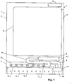
- This has a housing 1, which is divided into an upper housing part 2 and a lower housing part 3.
- the upper housing part 2 there is a tub 5, the interior of which is accessible to the user via a user door 6 on the front 7 of the device.
- the dishes are cleaned in this tub in a known manner.
- the two housing parts 2, 3 are pivotally connected to one another via a hinge 4.
- the hinge 4 has a horizontal pivot axis in the region of the front 7 or another side of the device.
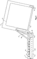
- the hinge 4 allows the two housing parts 2, 3 from the in Fig. 1 normal position shown in the in Fig. 2 bring shown maintenance position.
- the upper housing part 2 In the normal position, the upper housing part 2 is located vertically above the lower housing part 3, so that the upper housing part 2 rests on the lower housing part 3 and the lower housing part 3 forms a base of the device.
- the upper housing part 2 In the in Fig. 2 shown maintenance position, the upper housing part 2 is slightly more than the normal position than 90 ° so that it lies on the ground. As a result, the interior of the lower housing part 3 is accessible from above, as is the underside of the upper housing part.
- a process water system 8 which is shown only schematically as a functional block in the figures.
- it includes a circulation pump and a wastewater pump.
- the former serves to pump the process water in a circuit
- the second serves to drain process water that is no longer required.
- Corresponding process water systems are known for dishwashers and washing machines, for example from EP 2 206 824 and EP 2 215 955 .
- spray arms (not shown) are also provided in the tub 5, through which the process water is pumped in the circuit.
- a controller 9 of the device is also arranged in the upper housing part.
- a heat pump comprising a compressor 10, a condenser 11, an expansion valve (not shown) and an evaporator 12 is provided in the lower housing part.
- the condenser 11 and the evaporator 12 are preferably metal pipes with high thermal conductivity, e.g. around copper pipes (or aluminum or stainless steel).
- the function of the heat pump in the present example essentially corresponds to that according to EP 2 206 824 , ie it has the task of supplying heat to the process water if necessary.
- This heat becomes like at EP 2 206 824 withdrawn from a water tank 13.
- the water tank 13 is cooled, preferably below the freezing point of the water therein.
- Water is understood to mean a liquid which consists of at least 25% water. Instead of water, however, there can also be another heat storage material in the tank 13.
- the tank 13 is arranged in the lower housing part and is in thermal contact with the evaporator 12 of the heat pump.
- the evaporator 12 runs in loops or turns, in particular in a meandering shape, through the tank 13 in order to achieve a large heat transfer surface.
- the condenser 11 is located above the tank 13. It is preferably separated from the interior of the tank 13 by a cover 14.
- the lid 14 can be thermally insulated.
- the condenser 11 is part of a coaxial heat exchanger 15 arranged above the tank 13, through which process water is led from the upper housing part 2 in order to heat this process water.
- Flexible hoses 16, 17 serve to connect the heat exchanger 15 to the process water system 8 in the upper housing part 2.
- the hoses are designed so that they can pivot between the normal position ( Fig. 1 ) and the maintenance position ( Fig. 2 ) without damage or can be separated easily or automatically.
- plug connections can also be used.
- a pump 18 is also provided, which serves to pump the process water between the upper and lower housing parts.
- this pump can be dispensed with by supplying the condenser with the circulation pump of the dishwasher.
- An important task of the pump 18 is to convey process water from the heat exchanger 15 into the upper housing part and to empty the heat exchanger 15 in order to avoid standing water. This improves device hygiene and prevents odors.
- the compressor 10 of the heat pump is arranged on the side of the tank 13, that is to say horizontally next to the tank, so that despite its height it fits well in the lower housing part 3.
- the arrangement shown allows a compact structure of the components required in connection with the heat pump.
- the upper housing part 2 and the lower housing part 3 are first connected to one another via the hinge 4 in FIG Fig. 2 maintenance position shown interconnected. Then the hoses 16 and 17 are assembled. Then the upper part in the in Fig. 1 shown normal position can be pivoted.
- Another advantage is that the device can be easily opened by a single person when servicing. This saves costs for a second person or a device that would be required to separate the upper part of the device.
Landscapes
- Engineering & Computer Science (AREA)
- Textile Engineering (AREA)
- Structures Of Non-Positive Displacement Pumps (AREA)
- Washing And Drying Of Tableware (AREA)
- Heat-Pump Type And Storage Water Heaters (AREA)
Description
- Die Erfindung betrifft einen Geschirrspüler mit einem Gehäuse, einem im Gehäuse angeordneten Bottich und mit einer Wärmepumpe.
- Geräte dieser Art sind in
EP 2 206 824 undEP 2 215 955 beschrieben. Dabei dient die Wärmepumpe dazu, die Energieeffizienz des Geräts zu verbessern. Der mechanische Aufbau der Geräte wird in diesen Dokumenten allerdings nicht näher beschrieben. InWO 2006/097901 ist eine Wasch/Trocknerkombination mit einer Wärmepumpe im Sockelteil beschrieben, wobei sich zum Reinigen von Filtern der Oberteil mit der Waschmaschine vom Unterteil mit der Wärmepumpe trennen lässt. - Es stellt sich die Aufgabe, einen Geschirrspüler dieser Art mit einem zweckmässigen mechanischen Aufbau bereitzustellen.
- Diese Aufgabe wird vom Geschirrspüler gemäss Anspruch 1 gelöst. Demgemäss ist das Gehäuse des Geräts also in einen oberen Gehäuseteil und einen unteren Gehäuseteil unterteilt, wobei der untere Gehäuseteil sich unterhalb des oberen Gehäuseteils befindet und wobei die beiden Gehäuseteile voneinander trennbar sind. Die Wärmepumpe, und insbesondere deren Kompressor, Verdampfer, Drosselorgan bzw. Expansionsventil und Kondensator, wird im unteren Gehäuseteil angeordnet. Und im oberen Gehäuseteil (2) sind eine Gerätesteuerung (9) und ein Prozesswassersystem (8) umfassend eine Zirkulationspumpe und eine Abwasserpumpe angeordnet. Auf diese Weise entsteht ein modularer Aufbau, bei welchem die Komponenten der Wärmepumpe gut zugänglich sind, und bei welchem auch die Unterseite des oberen Gehäuseteils gut erreicht werden kann.
- Die beiden Gehäuseteile sind in dem Sinne "voneinander trennbar", dass sie ohne Zerstörung von Teilen und reversibel voneinander getrennt werden können.
- Die Anordnung der Wärmepumpe im unteren Gehäuseteil hat weiter den Vorteil, dass die schweren Komponenten (insbesondere der Kompressor) tief angeordnet sind, während die dem Benutzer zugänglichen Komponenten, insbesondere der Bottich, hoch angeordnet und gut zugänglich sind.
- In einer besonders bevorzugten Ausführung ist ein Scharnier vorgesehen, das die beiden Gehäuseteile schwenkbar verbindet. Dies erleichtert den Zugang zum unteren Gehäuseteil sowie zur Unterseite des oberen Gehäuseteils. Der obere Gehäuseteil kann in einfacher Weise zur Seite geschwenkt werden. Kompressoren dürfen nicht gekippt werden. Ein weiterer Vorteil ist somit, dass der Kompressor auch im Servicefall immer in der aufgestellten Lage bleibt.
- Wie insbesondere in
EP 2 206 824 gelehrt, kann der Wärmepumpe in thermischem Kontakt mit einem Tank stehen. Ein derartiger Tank, insbesondere in Form eines Wassertanks, wird vorzugsweise auch im unteren Gehäuseteil angeordnet. - Weitere Ausgestaltungen, Vorteile und Anwendungen der Erfindung ergeben sich aus den abhängigen Ansprüchen und aus der nun folgenden Beschreibung anhand der Figuren. Dabei zeigen:
-
Fig. 1 einen Schnitt durch einen Geschirrspüler, und -
Fig. 2 den Geschirrspüler nachFig. 1 mit umgeschwenkten oberen Gehäuseteil. - In den Figuren wird die Erfindung in Form eines Geschirrspülers dargestellt. Dieser besitzt ein Gehäuse 1, welches in einen oberen Gehäuseteil 2 und einen unteren Gehäuseteil 3 unterteilt ist.
- Im oberen Gehäuseteil 2 befindet sich ein Bottich 5, dessen Innenraum für den Benutzer über eine Benutzertüre 6 an der Vorderseite 7 des Geräts zugänglich ist. In diesem Bottich wird das Spülgut in bekannter Weise gereinigt.
- Die beiden Gehäuseteile 2, 3 sind über ein Scharnier 4 schwenkbar miteinander verbunden. Im gezeigten Beispiel besitzt das Scharnier 4 eine horizontale Schwenkachse im Bereich der Vorderseite 7 oder einer anderen Seite des Geräts.
- Das Scharnier 4 erlaubt es, die beiden Gehäuseteile 2, 3 aus der in
Fig. 1 gezeigten Normalposition in die inFig. 2 gezeigte Wartungsposition zu bringen. In der Normalposition befindet sich der obere Gehäuseteil 2 vertikal über dem unteren Gehäuseteil 3, so dass der obere Gehäuseteil 2 auf dem unteren Gehäuseteil 3 ruht und der untere Gehäuseteil 3 einen Sockel des Geräts bildet. In der inFig. 2 gezeigten Wartungsposition ist der obere Gehäuseteil 2 gegenüber der Normalposition um etwas mehr als 90° verschwenkt worden, so dass er am Boden aufliegt. Dadurch wird das Innere des unteren Gehäuseteils 3 von oben zugänglich, ebenso wie die Unterseite des oberen Gehäuseteils. - Im oberen Gehäuseteil 2 befindet sich ein Prozesswassersystem 8, das in den Figuren nur schematisch als Funktionsblock dargestellt ist. Es umfasst insbesondere eine Zirkulationspumpe sowie eine Abwasserpumpe. Erstere dient dazu, das Prozesswasser in einem Kreislauf umzupumpen, Zweitere dient dem Abführen von nicht mehr benötigtem Prozesswasser. Entsprechende Prozesswassersysteme sind für Geschirrspüler und Waschmaschinen bekannt, beispielsweise aus
EP 2 206 824 undEP 2 215 955 . Bei einem Geschirrspüler sind im Bottich 5 zudem in bekannter Weise Sprüharme (nicht gezeigt) vorgesehen, durch welche das Prozesswasser im Kreislauf gepumpt wird. - Im oberen Gehäuseteil ist weiter eine Steuerung 9 des Geräts angeordnet.
- Im unteren Gehäuseteil ist eine Wärmepumpe umfassend einen Kompressor 10, einen Kondensator 11, ein Expansionsventil (nicht gezeigt) sowie einen Verdampfer 12 vorgesehen. Beim Kondensator 11 und dem Verdampfer 12 handelt es sich vorzugsweise um Metallrohre mit hoher Wärmeleitfähigkeit, z.B. um Kupferrohre (oder Aluminium oder Edelstahl).
- Die Funktionsweise der Wärmepumpe entspricht im vorliegenden Beispiel im Wesentlichen jener gemäss
EP 2 206 824 , d.h. sie hat die Aufgabe, dem Prozesswasser bei Bedarf Wärme zuzuführen. Diese Wärme wird wie beiEP 2 206 824 einem Wassertank 13 entzogen. Dabei wird der Wassertank 13 abgekühlt, vorzugsweise unter den Gefrierpunkt des sich darin befindlichen Wassers. Unter "Wasser" ist dabei eine Flüssigkeit zu verstehen, welche zumindest aus 25% Wasser besteht. Anstelle von Wasser kann sich jedoch auch ein anderes Wärmespeichermaterial im Tank 13 befinden. - Der Tank 13 ist im unteren Gehäuseteil angeordnet und steht in thermischem Kontakt mit dem Verdampfer 12 der Wärmepumpe. Der Verdampfer 12 verläuft in Schleifen oder Windungen, insbesondere mäanderförmig, durch den Tank 13, um eine grosse Wärmeübergangs-Oberfläche zu erreichen.
- Oberhalb des Tanks 13 befindet sich der Kondensator 11. Vorzugsweise ist er vom Innenraum des Tanks 13 durch einen Deckel 14 getrennt. Der Deckel 14 kann wärmeisoliert sein. Der Kondensator 11 ist Teil eines über dem Tank 13 angeordneten Koaxial-Wärmetauschers 15, durch welchen Prozesswasser aus dem oberen Gehäuseteil 2 geführt wird, um dieses Prozesswasser zu erwärmen. Flexible Schläuche 16, 17 dienen dazu, den Wärmetauscher 15 mit dem Prozesswassersystem 8 im oberen Gehäuseteil 2 zu verbinden. Die Schläuche sind so ausgelegt, dass sie die Schwenkbewegung zwischen der Normalposition (
Fig. 1 ) und der Wartungsposition (Fig. 2 ) ohne Schaden zulassen oder einfach oder automatisch getrennt werden können. - Anstelle oder zusätzlich zu den flexiblen Schläuchen 16, 17 können auch Steckverbindungen eingesetzt werden.
- Im unteren Gehäuseteil 3 ist weiter eine Pumpe 18 vorgesehen, welche dazu dient, das Prozesswasser zwischen oberem und unterem Gehäuseteil umzupumpen. Alternativ kann auf diese Pumpe verzichtet werden, indem der Kondensator mit der Umwälzpumpe des Geschirrspülers versorgt wird. Eine wichtige Aufgabe der Pumpe 18 ist es, Prozesswasser aus dem Wärmetauscher 15 in den oberen Gehäuseteil zu fördern und den Wärmetauscher 15 so zu entleeren, um Standwasser zu vermeiden. Damit wird die Gerätehygiene verbessert und Geruchsbildung vermieden.
- Der Kompressor 10 der Wärmepumpe ist seitlich des Tanks 13, d.h. horizontal neben dem Tank, angeordnet, so dass er trotz seiner Höhe gut im unteren Gehäuseteil 3 Platz findet.
- Die gezeigte Anordnung erlaubt einen kompakten Aufbau der im Zusammenhang mit der Wärmepumpe benötigten Komponenten.
- Da die ganze Wärmepumpe im unteren Gehäuseteil angeordnet ist, kann sie einfach ausgewechselt werden. Dies ist deshalb von besonderer Bedeutung, weil eine Reparatur allfälliger Schäden an der Wärmepumpe und des Kältemittelkreises in der Regel nicht vor Ort, sondern in einer Werkstatt durchgeführt werden muss.
- Da zudem die wichtigsten, im Zusammenhang mit der Wärmepumpe benötigten Komponenten (insbesondere der Kompressor 10, der Verdampfer 11, der Kondensator 12, der Tank 13 und gegebenenfalls die Pumpe 18) im unteren Gehäuseteil 3 angeordnet sind, während sich die für die Arbeit des Geräts auch ohne Wärmepumpe erforderlichen Komponenten, insbesondere die Gerätesteuerung 9 und das Hydrauliksystem 8, mit Zirkulationspumpe sowie Abwasserpumpe, im oberen Gehäuseteil befinden, ergibt sich ein modulares Gerätesystem, das es einem Haushaltsgeräte-Hersteller in einfacher Weise erlaubt, bei einer Geräteserie eine Ausführung mit und eine Ausführung ohne Wärmepumpe anzubieten. Das modulare System gibt Vorteile in der Montage oder auch in der Endprüfung.
- Zur Montage des Geräts werden zunächst der obere Gehäuseteil 2 und der untere Gehäuseteil 3 über das Scharnier 4 miteinander in der in
Fig. 2 gezeigten Wartungsposition miteinander verbunden. Sodann werden die Schläuche 16 und 17 montiert. Dann kann der obere Teil in die inFig. 1 gezeigte Normalposition verschwenkt werden. - Ein weiterer Vorteil ist es, dass im Servicefalle das Gerät von einer einzelnen Person problemlos geöffnet werden kann. Dies erspart Kosten für eine zweite Person oder eine Vorrichtung, die zum Trennen des oberen Geräteteiles erforderlich wäre.
- Während in der vorliegenden Anmeldung bevorzugte Ausführungen der Erfindung beschrieben sind, ist klar darauf hinzuweisen, dass die Erfindung nicht auf diese beschränkt ist und in auch anderer Weise innerhalb des Umfangs der folgenden Ansprüche ausgeführt werden kann.
Claims (12)
- Wasser führender Geschirrspüler, mit einem Gehäuse (1), einem im Gehäuse (1) angeordneten Bottich (5) und einer Wärmepumpe (10, 11, 12), dadurch gekennzeichnet, dass das Gehäuse einen oberen Gehäuseteil (2) und einen unterhalb des oberen Gehäuseteils (2) angeordneten unteren Gehäuseteil (3) aufweist, wobei die beiden Gehäuseteile voneinander mindestens teilweise trennbar sind, wobei die Wärmepumpe (10, 11, 12) im unteren Gehäuseteil (3) angeordnet ist und wobei im oberen Gehäuseteil (2) eine Gerätesteuerung (9) und ein Prozesswassersystem (8) umfassend eine Zirkulationspumpe und eine Abwasserpumpe angeordnet sind.
- Geschirrspüler nach Anspruch 1, wobei die Wärmepumpe (10, 11, 12) einen Kompressor (10), einen Verdampfer (11) und einen Kondensator (12) aufweist, die im unteren Gehäuseteil (3) angeordnet sind.
- Geschirrspüler nach einem der vorangehenden Ansprüche mit einem Scharnier (4), das die beiden Gehäuseteile (2, 3) schwenkbar verbindet.
- Geschirrspüler nach Anspruch 3, wobei das Scharnier (4) eine Schwenkbewegung der beiden Gehäuseteile (2, 3) um mindestens 90° erlaubt
- Geschirrspüler nach einem der Ansprüche 3 oder 4 mit einer Benutzertüre (6) an einer Vorderseite (7) des Geschirrspülers, wobei das Scharnier (4) eine horizontale, an einer Seite(7) liegende Schwenkachse hat.
- Geschirrspüler nach einem der vorangehenden Ansprüche, wobei im unteren Gehäuseteil (3) mindestens ein Wärmetauscher (15) angeordnet ist, der über mindestens einen flexiblen Schlauch (16, 17) oder über mindestens eine Steckverbindung mit einem Prozesswassersystem (8) im oberen Gehäuseteil (2) verbunden ist.
- Geschirrspüler nach den Ansprüchen 3 und 6, wobei der Schlauch derart ausgestaltet ist, dass er eine Schwenkbewegung der Gehäuseteile (2, 3) zwischen einer Normalposition und einer Wartungsposition zulässt, insbesondere eine Schwenkbewegung um mindestens 90°.
- Geschirrspüler nach einem der Ansprüche 6 oder 7, wobei im unteren Gehäuseteil (3) eine Pumpe (18) angeordnet ist, um Prozesswasser aus dem Wärmetauscher (15) in den oberen Gehäuseteil (2) zu pumpen.
- Geschirrspüler nach einem der vorangehenden Ansprüche, wobei im unteren Gehäuseteil (3) ein Tank (13), insbesondere ein Wassertank, angeordnet ist, der in thermischem Kontakt mit einem Verdampfer (11) der Wärmepumpe (10, 11, 12) steht.
- Geschirrspüler nach Anspruch 9, wobei oberhalb des Tanks (13) im unteren Gehäuseteil (3) ein Kondensator (12) der Wärmepumpe (10, 11, 12) angeordnet ist.
- Geschirrspüler nach den Ansprüchen 6 und 10, wobei der Wärmetauscher (15) ebenfalls oberhalb des Tanks (13) angeordnet ist.
- Geschirrspüler nach einem der Ansprüche 9 bis 11, wobei ein Kompressor (10) der Wärmepumpe (10, 11, 12) seitlich vom Tank (13) angeordnet ist.
Priority Applications (2)
| Application Number | Priority Date | Filing Date | Title |
|---|---|---|---|
| SI201231827T SI2443983T1 (sl) | 2012-01-27 | 2012-01-27 | Gospodinjska naprava s toplotno črpalko, razmeščeno spodaj |
| EP12000527.7A EP2443983B1 (de) | 2012-01-27 | 2012-01-27 | Haushaltgerät mit unten liegender Wärmepumpe |
Applications Claiming Priority (1)
| Application Number | Priority Date | Filing Date | Title |
|---|---|---|---|
| EP12000527.7A EP2443983B1 (de) | 2012-01-27 | 2012-01-27 | Haushaltgerät mit unten liegender Wärmepumpe |
Publications (3)
| Publication Number | Publication Date |
|---|---|
| EP2443983A2 EP2443983A2 (de) | 2012-04-25 |
| EP2443983A3 EP2443983A3 (de) | 2012-08-22 |
| EP2443983B1 true EP2443983B1 (de) | 2020-06-17 |
Family
ID=45560680
Family Applications (1)
| Application Number | Title | Priority Date | Filing Date |
|---|---|---|---|
| EP12000527.7A Active EP2443983B1 (de) | 2012-01-27 | 2012-01-27 | Haushaltgerät mit unten liegender Wärmepumpe |
Country Status (2)
| Country | Link |
|---|---|
| EP (1) | EP2443983B1 (de) |
| SI (1) | SI2443983T1 (de) |
Cited By (5)
| Publication number | Priority date | Publication date | Assignee | Title |
|---|---|---|---|---|
| EP4275573A4 (de) * | 2022-02-18 | 2024-07-31 | Guangdong Midea White Home Appliance Technology Innovation Center Co., Ltd. | Wärmepumpengeschirrspülmaschine |
| WO2025095547A1 (ko) * | 2023-11-02 | 2025-05-08 | 엘지전자 주식회사 | 식기세척기 |
| EP4516195A4 (de) * | 2022-06-14 | 2025-07-02 | Foshan Shunde Midea Washing Appliances Mfg Co Ltd | Waschvorrichtung |
| WO2025228536A1 (en) * | 2024-05-03 | 2025-11-06 | Electrolux Appliances Aktiebolag | Dishwasher with heat pump |
| WO2025228537A1 (en) * | 2024-05-03 | 2025-11-06 | Electrolux Appliances Aktiebolag | Dishwasher with heat pump |
Families Citing this family (7)
| Publication number | Priority date | Publication date | Assignee | Title |
|---|---|---|---|---|
| JP6043956B2 (ja) * | 2013-01-23 | 2016-12-14 | パナソニックIpマネジメント株式会社 | 洗濯乾燥機 |
| EP2799612B1 (de) * | 2013-05-02 | 2015-12-09 | Electrolux Appliances Aktiebolag | Wärmepumpenvorrichtung zur Wäschebehandlung |
| EP3467187B1 (de) | 2017-10-09 | 2021-12-22 | Whirlpool Corporation | Zur verwendung in einer maschine zum trocknen von wäsche konfigurierter filter und mit solch einem filter ausgestattete maschine zum trocknen von wäsche |
| CN118806190A (zh) * | 2023-04-06 | 2024-10-22 | 青岛海尔洗碗机有限公司 | 包括热泵装置的洗碗机 |
| DE102023207594A1 (de) * | 2023-08-08 | 2025-02-13 | BSH Hausgeräte GmbH | Geschirrspülmaschine mit einer Wärmepumpenanordnung, sowie Wärmeübertragungsvorrichtung für diese |
| DE102023207593B4 (de) * | 2023-08-08 | 2026-07-23 | BSH Hausgeräte GmbH | Geschirrspülmaschine mit einer Wärmepumpe als modulare Einheit |
| WO2025228535A1 (en) | 2024-05-03 | 2025-11-06 | Electrolux Appliances Aktiebolag | Dishwasher with heat pump |
Family Cites Families (9)
| Publication number | Priority date | Publication date | Assignee | Title |
|---|---|---|---|---|
| DE1865993U (de) * | 1962-11-24 | 1963-01-24 | Karl Winterhalter Fa Ing | Geschirr-wasch- und spuelmaschine, die in einer reihe mit anderen kuechengeraeten auf dem kuechenfussboden aufgestellt ist. |
| DE3614389C1 (de) * | 1986-04-28 | 1987-09-03 | Bosch Siemens Hausgeraete | Geschirrspuelmaschine |
| DE4212700A1 (de) * | 1992-04-16 | 1993-10-21 | Licentia Gmbh | Wäschetrockner mit einem Wärmepumpenkreis |
| EP1634984A1 (de) * | 2004-09-09 | 2006-03-15 | Electrolux Home Products Corporation N.V. | Kombinierte Wasch- und Trockenmachine mit Wärmepumpe |
| WO2006097901A2 (en) * | 2005-03-16 | 2006-09-21 | Arcelik Anonim Sirketi | A washer/dryer |
| US20080289664A1 (en) * | 2007-05-24 | 2008-11-27 | Rockwell Anthony L | Modular drip pan and component mounting assembly for a dishwasher |
| EP2064982B1 (de) | 2009-02-09 | 2012-06-27 | V-Zug AG | Geschirrspüler mit Wärmepumpe |
| IT1397773B1 (it) * | 2009-11-19 | 2013-01-24 | Bitron Spa | Macchina lavastoviglie. |
| SI2206824T1 (sl) | 2010-02-16 | 2013-11-29 | V-Zug Ag | Gospodinjski stroj s kadico, toplotno ÄŤrpalko in vsebnikom |
-
2012
- 2012-01-27 SI SI201231827T patent/SI2443983T1/sl unknown
- 2012-01-27 EP EP12000527.7A patent/EP2443983B1/de active Active
Non-Patent Citations (1)
| Title |
|---|
| None * |
Cited By (6)
| Publication number | Priority date | Publication date | Assignee | Title |
|---|---|---|---|---|
| EP4275573A4 (de) * | 2022-02-18 | 2024-07-31 | Guangdong Midea White Home Appliance Technology Innovation Center Co., Ltd. | Wärmepumpengeschirrspülmaschine |
| US12396615B2 (en) | 2022-02-18 | 2025-08-26 | Guangdong Midea White Home Appliance Technology Innovation Center Co., Ltd. | Heat pump dishwasher |
| EP4516195A4 (de) * | 2022-06-14 | 2025-07-02 | Foshan Shunde Midea Washing Appliances Mfg Co Ltd | Waschvorrichtung |
| WO2025095547A1 (ko) * | 2023-11-02 | 2025-05-08 | 엘지전자 주식회사 | 식기세척기 |
| WO2025228536A1 (en) * | 2024-05-03 | 2025-11-06 | Electrolux Appliances Aktiebolag | Dishwasher with heat pump |
| WO2025228537A1 (en) * | 2024-05-03 | 2025-11-06 | Electrolux Appliances Aktiebolag | Dishwasher with heat pump |
Also Published As
| Publication number | Publication date |
|---|---|
| EP2443983A2 (de) | 2012-04-25 |
| EP2443983A3 (de) | 2012-08-22 |
| SI2443983T1 (sl) | 2020-10-30 |
Similar Documents
| Publication | Publication Date | Title |
|---|---|---|
| EP2443983A2 (de) | Haushaltgerät mit unten liegender Wärmepumpe | |
| DE112010001512T5 (de) | Geschirrspüler | |
| EP2543305B1 (de) | Geschirrspülmaschine | |
| EP3085293B1 (de) | Sprüharmanordnung und geschirrspülmaschine | |
| DE102019131954A1 (de) | Geschirrspülmaschine mit Wärmepumpe | |
| DE4116228A1 (de) | Insbesondere fuer kleinteile ausgelegte geschirrspuelmaschine | |
| DE102019121736A1 (de) | Geschirrspülmaschine und Verfahren zum Betrieb einer Geschirrspülmaschine | |
| DE69716066T2 (de) | Getränkeautomat mit einer Komponentenanordnung zur Erleichterung seiner Wartung | |
| DE102019131958A1 (de) | Geschirrspülmaschine mit Wärmepumpe | |
| EP2443984B1 (de) | Koaxial-Wärmetauscher für ein Haushaltgerät | |
| DE202013006209U1 (de) | Mischvorrichtung | |
| DE19509536A1 (de) | Kältemittelaufnahmetank-Baueinheit | |
| DE102011118272A1 (de) | Klimatisierungsvorrichtung | |
| EP3733040A1 (de) | Wasserführendes haushaltsgerät | |
| DE9403745U1 (de) | Hochdruckreiniger | |
| DE112015007101T5 (de) | Außeneinheit für Kältekreislaufvorrichtung | |
| EP2585769B1 (de) | Elektrischer durchlauferhitzer | |
| DE102016119472B4 (de) | Gerätehalterung | |
| DE202009005147U1 (de) | Temperaturkontrollgerät für eine Elektro-Fritteuse | |
| DE2801638A1 (de) | Abwasserbehaelter mit einem verdampfer fuer eine waermepumpe zur waermerueckgewinnung | |
| DE3440862A1 (de) | Mobiler sanitaerwagen | |
| WO2013110496A1 (de) | Haushaltskältegerät mit einem innenbehälter und einem sockel | |
| EP0582034A2 (de) | Vorrichtung zur Zufuhr oder zum Absaugen eines Mediums | |
| DE102007017011A1 (de) | Kühl- und/oder Gefriergerät | |
| DE102018214482A1 (de) | Baugruppenmodul für ein Haushaltskühlgerät, umfassend einen Wasserfilter und ein Ventil, und Haushaltskühlgerät |
Legal Events
| Date | Code | Title | Description |
|---|---|---|---|
| AK | Designated contracting states |
Kind code of ref document: A2 Designated state(s): AL AT BE BG CH CY CZ DE DK EE ES FI FR GB GR HR HU IE IS IT LI LT LU LV MC MK MT NL NO PL PT RO RS SE SI SK SM TR |
|
| AX | Request for extension of the european patent |
Extension state: BA ME |
|
| PUAI | Public reference made under article 153(3) epc to a published international application that has entered the european phase |
Free format text: ORIGINAL CODE: 0009012 |
|
| PUAL | Search report despatched |
Free format text: ORIGINAL CODE: 0009013 |
|
| AK | Designated contracting states |
Kind code of ref document: A3 Designated state(s): AL AT BE BG CH CY CZ DE DK EE ES FI FR GB GR HR HU IE IS IT LI LT LU LV MC MK MT NL NO PL PT RO RS SE SI SK SM TR |
|
| AX | Request for extension of the european patent |
Extension state: BA ME |
|
| RIC1 | Information provided on ipc code assigned before grant |
Ipc: A47L 15/48 20060101ALI20120718BHEP Ipc: D06F 58/20 20060101ALI20120718BHEP Ipc: A47L 15/42 20060101AFI20120718BHEP Ipc: D06F 39/12 20060101ALI20120718BHEP Ipc: D06F 39/00 20060101ALI20120718BHEP |
|
| 17P | Request for examination filed |
Effective date: 20130213 |
|
| RAP1 | Party data changed (applicant data changed or rights of an application transferred) |
Owner name: V-ZUG AG |
|
| GRAP | Despatch of communication of intention to grant a patent |
Free format text: ORIGINAL CODE: EPIDOSNIGR1 |
|
| STAA | Information on the status of an ep patent application or granted ep patent |
Free format text: STATUS: GRANT OF PATENT IS INTENDED |
|
| INTG | Intention to grant announced |
Effective date: 20200310 |
|
| RIN1 | Information on inventor provided before grant (corrected) |
Inventor name: LOICHINGER, ALBERT JOHANN Inventor name: BON, PATRICK Inventor name: DOBER, ERNST |
|
| GRAS | Grant fee paid |
Free format text: ORIGINAL CODE: EPIDOSNIGR3 |
|
| GRAA | (expected) grant |
Free format text: ORIGINAL CODE: 0009210 |
|
| STAA | Information on the status of an ep patent application or granted ep patent |
Free format text: STATUS: THE PATENT HAS BEEN GRANTED |
|
| AK | Designated contracting states |
Kind code of ref document: B1 Designated state(s): AL AT BE BG CH CY CZ DE DK EE ES FI FR GB GR HR HU IE IS IT LI LT LU LV MC MK MT NL NO PL PT RO RS SE SI SK SM TR |
|
| REG | Reference to a national code |
Ref country code: GB Ref legal event code: FG4D Free format text: NOT ENGLISH |
|
| REG | Reference to a national code |
Ref country code: CH Ref legal event code: NV Representative=s name: E. BLUM AND CO. AG PATENT- UND MARKENANWAELTE , CH Ref country code: CH Ref legal event code: EP |
|
| REG | Reference to a national code |
Ref country code: DE Ref legal event code: R096 Ref document number: 502012016136 Country of ref document: DE |
|
| REG | Reference to a national code |
Ref country code: IE Ref legal event code: FG4D Free format text: LANGUAGE OF EP DOCUMENT: GERMAN |
|
| REG | Reference to a national code |
Ref country code: AT Ref legal event code: REF Ref document number: 1280339 Country of ref document: AT Kind code of ref document: T Effective date: 20200715 |
|
| REG | Reference to a national code |
Ref country code: SE Ref legal event code: TRGR |
|
| PG25 | Lapsed in a contracting state [announced via postgrant information from national office to epo] |
Ref country code: FI Free format text: LAPSE BECAUSE OF FAILURE TO SUBMIT A TRANSLATION OF THE DESCRIPTION OR TO PAY THE FEE WITHIN THE PRESCRIBED TIME-LIMIT Effective date: 20200617 Ref country code: NO Free format text: LAPSE BECAUSE OF FAILURE TO SUBMIT A TRANSLATION OF THE DESCRIPTION OR TO PAY THE FEE WITHIN THE PRESCRIBED TIME-LIMIT Effective date: 20200917 Ref country code: GR Free format text: LAPSE BECAUSE OF FAILURE TO SUBMIT A TRANSLATION OF THE DESCRIPTION OR TO PAY THE FEE WITHIN THE PRESCRIBED TIME-LIMIT Effective date: 20200918 Ref country code: LT Free format text: LAPSE BECAUSE OF FAILURE TO SUBMIT A TRANSLATION OF THE DESCRIPTION OR TO PAY THE FEE WITHIN THE PRESCRIBED TIME-LIMIT Effective date: 20200617 |
|
| REG | Reference to a national code |
Ref country code: LT Ref legal event code: MG4D |
|
| REG | Reference to a national code |
Ref country code: NL Ref legal event code: MP Effective date: 20200617 |
|
| PG25 | Lapsed in a contracting state [announced via postgrant information from national office to epo] |
Ref country code: BG Free format text: LAPSE BECAUSE OF FAILURE TO SUBMIT A TRANSLATION OF THE DESCRIPTION OR TO PAY THE FEE WITHIN THE PRESCRIBED TIME-LIMIT Effective date: 20200917 Ref country code: HR Free format text: LAPSE BECAUSE OF FAILURE TO SUBMIT A TRANSLATION OF THE DESCRIPTION OR TO PAY THE FEE WITHIN THE PRESCRIBED TIME-LIMIT Effective date: 20200617 Ref country code: LV Free format text: LAPSE BECAUSE OF FAILURE TO SUBMIT A TRANSLATION OF THE DESCRIPTION OR TO PAY THE FEE WITHIN THE PRESCRIBED TIME-LIMIT Effective date: 20200617 Ref country code: RS Free format text: LAPSE BECAUSE OF FAILURE TO SUBMIT A TRANSLATION OF THE DESCRIPTION OR TO PAY THE FEE WITHIN THE PRESCRIBED TIME-LIMIT Effective date: 20200617 |
|
| PG25 | Lapsed in a contracting state [announced via postgrant information from national office to epo] |
Ref country code: AL Free format text: LAPSE BECAUSE OF FAILURE TO SUBMIT A TRANSLATION OF THE DESCRIPTION OR TO PAY THE FEE WITHIN THE PRESCRIBED TIME-LIMIT Effective date: 20200617 Ref country code: NL Free format text: LAPSE BECAUSE OF FAILURE TO SUBMIT A TRANSLATION OF THE DESCRIPTION OR TO PAY THE FEE WITHIN THE PRESCRIBED TIME-LIMIT Effective date: 20200617 |
|
| PG25 | Lapsed in a contracting state [announced via postgrant information from national office to epo] |
Ref country code: ES Free format text: LAPSE BECAUSE OF FAILURE TO SUBMIT A TRANSLATION OF THE DESCRIPTION OR TO PAY THE FEE WITHIN THE PRESCRIBED TIME-LIMIT Effective date: 20200617 Ref country code: PT Free format text: LAPSE BECAUSE OF FAILURE TO SUBMIT A TRANSLATION OF THE DESCRIPTION OR TO PAY THE FEE WITHIN THE PRESCRIBED TIME-LIMIT Effective date: 20201019 Ref country code: RO Free format text: LAPSE BECAUSE OF FAILURE TO SUBMIT A TRANSLATION OF THE DESCRIPTION OR TO PAY THE FEE WITHIN THE PRESCRIBED TIME-LIMIT Effective date: 20200617 Ref country code: SM Free format text: LAPSE BECAUSE OF FAILURE TO SUBMIT A TRANSLATION OF THE DESCRIPTION OR TO PAY THE FEE WITHIN THE PRESCRIBED TIME-LIMIT Effective date: 20200617 Ref country code: EE Free format text: LAPSE BECAUSE OF FAILURE TO SUBMIT A TRANSLATION OF THE DESCRIPTION OR TO PAY THE FEE WITHIN THE PRESCRIBED TIME-LIMIT Effective date: 20200617 Ref country code: CZ Free format text: LAPSE BECAUSE OF FAILURE TO SUBMIT A TRANSLATION OF THE DESCRIPTION OR TO PAY THE FEE WITHIN THE PRESCRIBED TIME-LIMIT Effective date: 20200617 |
|
| PG25 | Lapsed in a contracting state [announced via postgrant information from national office to epo] |
Ref country code: IS Free format text: LAPSE BECAUSE OF FAILURE TO SUBMIT A TRANSLATION OF THE DESCRIPTION OR TO PAY THE FEE WITHIN THE PRESCRIBED TIME-LIMIT Effective date: 20201017 Ref country code: PL Free format text: LAPSE BECAUSE OF FAILURE TO SUBMIT A TRANSLATION OF THE DESCRIPTION OR TO PAY THE FEE WITHIN THE PRESCRIBED TIME-LIMIT Effective date: 20200617 Ref country code: SK Free format text: LAPSE BECAUSE OF FAILURE TO SUBMIT A TRANSLATION OF THE DESCRIPTION OR TO PAY THE FEE WITHIN THE PRESCRIBED TIME-LIMIT Effective date: 20200617 |
|
| REG | Reference to a national code |
Ref country code: DE Ref legal event code: R097 Ref document number: 502012016136 Country of ref document: DE |
|
| PLBE | No opposition filed within time limit |
Free format text: ORIGINAL CODE: 0009261 |
|
| STAA | Information on the status of an ep patent application or granted ep patent |
Free format text: STATUS: NO OPPOSITION FILED WITHIN TIME LIMIT |
|
| PG25 | Lapsed in a contracting state [announced via postgrant information from national office to epo] |
Ref country code: DK Free format text: LAPSE BECAUSE OF FAILURE TO SUBMIT A TRANSLATION OF THE DESCRIPTION OR TO PAY THE FEE WITHIN THE PRESCRIBED TIME-LIMIT Effective date: 20200617 |
|
| 26N | No opposition filed |
Effective date: 20210318 |
|
| PG25 | Lapsed in a contracting state [announced via postgrant information from national office to epo] |
Ref country code: MC Free format text: LAPSE BECAUSE OF FAILURE TO SUBMIT A TRANSLATION OF THE DESCRIPTION OR TO PAY THE FEE WITHIN THE PRESCRIBED TIME-LIMIT Effective date: 20200617 |
|
| GBPC | Gb: european patent ceased through non-payment of renewal fee |
Effective date: 20210127 |
|
| PG25 | Lapsed in a contracting state [announced via postgrant information from national office to epo] |
Ref country code: LU Free format text: LAPSE BECAUSE OF NON-PAYMENT OF DUE FEES Effective date: 20210127 |
|
| REG | Reference to a national code |
Ref country code: BE Ref legal event code: MM Effective date: 20210131 |
|
| PG25 | Lapsed in a contracting state [announced via postgrant information from national office to epo] |
Ref country code: FR Free format text: LAPSE BECAUSE OF NON-PAYMENT OF DUE FEES Effective date: 20210131 |
|
| PG25 | Lapsed in a contracting state [announced via postgrant information from national office to epo] |
Ref country code: GB Free format text: LAPSE BECAUSE OF NON-PAYMENT OF DUE FEES Effective date: 20210127 |
|
| PG25 | Lapsed in a contracting state [announced via postgrant information from national office to epo] |
Ref country code: IE Free format text: LAPSE BECAUSE OF NON-PAYMENT OF DUE FEES Effective date: 20210127 |
|
| REG | Reference to a national code |
Ref country code: AT Ref legal event code: MM01 Ref document number: 1280339 Country of ref document: AT Kind code of ref document: T Effective date: 20210127 |
|
| PG25 | Lapsed in a contracting state [announced via postgrant information from national office to epo] |
Ref country code: AT Free format text: LAPSE BECAUSE OF NON-PAYMENT OF DUE FEES Effective date: 20210127 |
|
| PG25 | Lapsed in a contracting state [announced via postgrant information from national office to epo] |
Ref country code: IS Free format text: LAPSE BECAUSE OF FAILURE TO SUBMIT A TRANSLATION OF THE DESCRIPTION OR TO PAY THE FEE WITHIN THE PRESCRIBED TIME-LIMIT Effective date: 20201017 |
|
| PG25 | Lapsed in a contracting state [announced via postgrant information from national office to epo] |
Ref country code: BE Free format text: LAPSE BECAUSE OF NON-PAYMENT OF DUE FEES Effective date: 20210131 |
|
| PG25 | Lapsed in a contracting state [announced via postgrant information from national office to epo] |
Ref country code: HU Free format text: LAPSE BECAUSE OF FAILURE TO SUBMIT A TRANSLATION OF THE DESCRIPTION OR TO PAY THE FEE WITHIN THE PRESCRIBED TIME-LIMIT; INVALID AB INITIO Effective date: 20120127 Ref country code: CY Free format text: LAPSE BECAUSE OF FAILURE TO SUBMIT A TRANSLATION OF THE DESCRIPTION OR TO PAY THE FEE WITHIN THE PRESCRIBED TIME-LIMIT Effective date: 20200617 |
|
| PGFP | Annual fee paid to national office [announced via postgrant information from national office to epo] |
Ref country code: SI Payment date: 20230119 Year of fee payment: 12 Ref country code: SE Payment date: 20230119 Year of fee payment: 12 Ref country code: IT Payment date: 20230120 Year of fee payment: 12 |
|
| P01 | Opt-out of the competence of the unified patent court (upc) registered |
Effective date: 20230425 |
|
| PG25 | Lapsed in a contracting state [announced via postgrant information from national office to epo] |
Ref country code: MK Free format text: LAPSE BECAUSE OF FAILURE TO SUBMIT A TRANSLATION OF THE DESCRIPTION OR TO PAY THE FEE WITHIN THE PRESCRIBED TIME-LIMIT Effective date: 20200617 |
|
| PG25 | Lapsed in a contracting state [announced via postgrant information from national office to epo] |
Ref country code: TR Free format text: LAPSE BECAUSE OF FAILURE TO SUBMIT A TRANSLATION OF THE DESCRIPTION OR TO PAY THE FEE WITHIN THE PRESCRIBED TIME-LIMIT Effective date: 20200617 |
|
| REG | Reference to a national code |
Ref country code: SE Ref legal event code: EUG |
|
| PG25 | Lapsed in a contracting state [announced via postgrant information from national office to epo] |
Ref country code: MT Free format text: LAPSE BECAUSE OF FAILURE TO SUBMIT A TRANSLATION OF THE DESCRIPTION OR TO PAY THE FEE WITHIN THE PRESCRIBED TIME-LIMIT Effective date: 20200617 |
|
| PG25 | Lapsed in a contracting state [announced via postgrant information from national office to epo] |
Ref country code: SI Free format text: LAPSE BECAUSE OF NON-PAYMENT OF DUE FEES Effective date: 20240128 |
|
| PG25 | Lapsed in a contracting state [announced via postgrant information from national office to epo] |
Ref country code: SI Free format text: LAPSE BECAUSE OF NON-PAYMENT OF DUE FEES Effective date: 20240128 |
|
| REG | Reference to a national code |
Ref country code: SI Ref legal event code: KO00 Effective date: 20241001 |
|
| PG25 | Lapsed in a contracting state [announced via postgrant information from national office to epo] |
Ref country code: IT Free format text: LAPSE BECAUSE OF NON-PAYMENT OF DUE FEES Effective date: 20240127 |
|
| PG25 | Lapsed in a contracting state [announced via postgrant information from national office to epo] |
Ref country code: SE Free format text: LAPSE BECAUSE OF NON-PAYMENT OF DUE FEES Effective date: 20240128 |
|
| REG | Reference to a national code |
Ref country code: CH Ref legal event code: U11 Free format text: ST27 STATUS EVENT CODE: U-0-0-U10-U11 (AS PROVIDED BY THE NATIONAL OFFICE) Effective date: 20260201 |
|
| PGFP | Annual fee paid to national office [announced via postgrant information from national office to epo] |
Ref country code: DE Payment date: 20260121 Year of fee payment: 15 |
|
| PGFP | Annual fee paid to national office [announced via postgrant information from national office to epo] |
Ref country code: CH Payment date: 20260201 Year of fee payment: 15 |