EP2441574A1 - Method and device for constructing open bases at end sections of tubular bag bodies - Google Patents
Method and device for constructing open bases at end sections of tubular bag bodies Download PDFInfo
- Publication number
- EP2441574A1 EP2441574A1 EP10187549A EP10187549A EP2441574A1 EP 2441574 A1 EP2441574 A1 EP 2441574A1 EP 10187549 A EP10187549 A EP 10187549A EP 10187549 A EP10187549 A EP 10187549A EP 2441574 A1 EP2441574 A1 EP 2441574A1
- Authority
- EP
- European Patent Office
- Prior art keywords
- bag body
- transport
- spreading tool
- tubular bag
- tool
- Prior art date
- Legal status (The legal status is an assumption and is not a legal conclusion. Google has not performed a legal analysis and makes no representation as to the accuracy of the status listed.)
- Granted
Links
- 238000000034 method Methods 0.000 title claims abstract description 25
- 239000004033 plastic Substances 0.000 claims abstract description 11
- 229920003023 plastic Polymers 0.000 claims abstract description 11
- 239000004744 fabric Substances 0.000 claims abstract description 9
- 239000002985 plastic film Substances 0.000 claims abstract description 8
- 230000007480 spreading Effects 0.000 claims description 86
- 238000003892 spreading Methods 0.000 claims description 86
- 238000003825 pressing Methods 0.000 claims description 29
- 230000015572 biosynthetic process Effects 0.000 claims description 10
- 229920006255 plastic film Polymers 0.000 claims description 7
- 230000003111 delayed effect Effects 0.000 claims description 3
- 230000006835 compression Effects 0.000 claims description 2
- 238000007906 compression Methods 0.000 claims description 2
- 230000032258 transport Effects 0.000 description 75
- 239000000463 material Substances 0.000 description 6
- 238000004519 manufacturing process Methods 0.000 description 5
- -1 polyethylene Polymers 0.000 description 4
- 230000008901 benefit Effects 0.000 description 3
- 239000006223 plastic coating Substances 0.000 description 3
- 230000008569 process Effects 0.000 description 3
- 239000004698 Polyethylene Substances 0.000 description 2
- 239000004743 Polypropylene Substances 0.000 description 2
- 125000004122 cyclic group Chemical group 0.000 description 2
- 238000012423 maintenance Methods 0.000 description 2
- 229920000573 polyethylene Polymers 0.000 description 2
- 229920001155 polypropylene Polymers 0.000 description 2
- 230000001360 synchronised effect Effects 0.000 description 2
- 230000004913 activation Effects 0.000 description 1
- 230000000712 assembly Effects 0.000 description 1
- 238000000429 assembly Methods 0.000 description 1
- 239000002131 composite material Substances 0.000 description 1
- 230000001419 dependent effect Effects 0.000 description 1
- 238000006073 displacement reaction Methods 0.000 description 1
- 230000000694 effects Effects 0.000 description 1
- 230000002349 favourable effect Effects 0.000 description 1
- 239000003302 ferromagnetic material Substances 0.000 description 1
- 239000000945 filler Substances 0.000 description 1
- 230000006872 improvement Effects 0.000 description 1
- 238000009434 installation Methods 0.000 description 1
- 238000004181 pedogenesis Methods 0.000 description 1
- 230000002441 reversible effect Effects 0.000 description 1
- 239000002689 soil Substances 0.000 description 1
- 238000011144 upstream manufacturing Methods 0.000 description 1
Images


Classifications
-
- B—PERFORMING OPERATIONS; TRANSPORTING
- B31—MAKING ARTICLES OF PAPER, CARDBOARD OR MATERIAL WORKED IN A MANNER ANALOGOUS TO PAPER; WORKING PAPER, CARDBOARD OR MATERIAL WORKED IN A MANNER ANALOGOUS TO PAPER
- B31B—MAKING CONTAINERS OF PAPER, CARDBOARD OR MATERIAL WORKED IN A MANNER ANALOGOUS TO PAPER
- B31B70/00—Making flexible containers, e.g. envelopes or bags
- B31B70/26—Folding sheets, blanks or webs
- B31B70/52—Folding sheets, blanks or webs by reciprocating or oscillating members other than plungers and dies, e.g. by fingers
-
- B—PERFORMING OPERATIONS; TRANSPORTING
- B31—MAKING ARTICLES OF PAPER, CARDBOARD OR MATERIAL WORKED IN A MANNER ANALOGOUS TO PAPER; WORKING PAPER, CARDBOARD OR MATERIAL WORKED IN A MANNER ANALOGOUS TO PAPER
- B31B—MAKING CONTAINERS OF PAPER, CARDBOARD OR MATERIAL WORKED IN A MANNER ANALOGOUS TO PAPER
- B31B2150/00—Flexible containers made from sheets or blanks, e.g. from flattened tubes
- B31B2150/001—Flexible containers made from sheets or blanks, e.g. from flattened tubes with square or cross bottom
- B31B2150/0014—Flexible containers made from sheets or blanks, e.g. from flattened tubes with square or cross bottom having their openings facing transversally to the direction of movement
-
- B—PERFORMING OPERATIONS; TRANSPORTING
- B31—MAKING ARTICLES OF PAPER, CARDBOARD OR MATERIAL WORKED IN A MANNER ANALOGOUS TO PAPER; WORKING PAPER, CARDBOARD OR MATERIAL WORKED IN A MANNER ANALOGOUS TO PAPER
- B31B—MAKING CONTAINERS OF PAPER, CARDBOARD OR MATERIAL WORKED IN A MANNER ANALOGOUS TO PAPER
- B31B2160/00—Shape of flexible containers
- B31B2160/10—Shape of flexible containers rectangular and flat, i.e. without structural provision for thickness of contents
- B31B2160/102—Shape of flexible containers rectangular and flat, i.e. without structural provision for thickness of contents obtained from essentially rectangular sheets
-
- B—PERFORMING OPERATIONS; TRANSPORTING
- B31—MAKING ARTICLES OF PAPER, CARDBOARD OR MATERIAL WORKED IN A MANNER ANALOGOUS TO PAPER; WORKING PAPER, CARDBOARD OR MATERIAL WORKED IN A MANNER ANALOGOUS TO PAPER
- B31B—MAKING CONTAINERS OF PAPER, CARDBOARD OR MATERIAL WORKED IN A MANNER ANALOGOUS TO PAPER
- B31B2160/00—Shape of flexible containers
- B31B2160/20—Shape of flexible containers with structural provision for thickness of contents
Abstract
Description
Die Erfindung betrifft ein Verfahren und eine Vorrichtung zum Ausbilden von offenen Böden an offenen Endbereichen von schlauchförmigen Sackkörpern, welche Sackkörper vorzugsweise aus einem Gewebe aus gereckten Kunststoffbändchen hergestellt sind, wobei die Sackkörper flachliegend in einer Transportrichtung quer zu ihrer Längserstreckung mit einer Transportgeschwindigkeit transportiert und während des Transports die zu faltenden Endbereiche der schlauchförmigen Sackkörper geöffnet werden.The invention relates to a method and a device for forming open trays at open end regions of tubular bag bodies, which bag bodies are preferably made from a fabric of stretched plastic tapes, wherein the bag body transported flat in a transport direction transversely to its longitudinal extent at a transport speed and during the Transports are opened to be folded end portions of the tubular bag body.
Kastensäcke, auch Kreuzbodensäcke genannt, sind Säcke von quaderförmiger Gestalt, die in Sackkonfektionsanlagen hergestellt werden, indem schlauchförmige Sackkörper bereitgestellt werden, deren offene Endbereiche zu Kreuzböden gefaltet werden. Die Sackkörper werden flach liegend durch die Konfektionsanlage geführt, so dass zwei Lagen des schlauchförmigen Sackkörpers aneinander anliegen. Zur Bodenbildung werden die beiden Lagen an den Endbereichen des schlauchförmigen Sackkörpers voneinander getrennt und eine der beiden Lagen wird als Seitenklappe um 180° auf sich selbst umgeklappt, wodurch ein offener Boden entsteht, bei dem die andere Lage eine zweite Seitenklappe bildet. Durch das Umklappen einer Lage am Endbereich des schlauchförmigen Sackkörpers entsteht am vorderen und hinteren Teil dieses Endbereichs jeweils ein dreieckiger Umschlag. Diesen Vorgang nennt man in der Fachsprache auch "Aufziehen". In weiterer Bearbeitungsabfolge können Ventilzettel eingelegt werden (zur Herstellung von "Kastenventilsäcken", die durch das Ventil hindurch mit Füllstutzen befüllbar sind) und wird die endgültige Bodenkonfiguration durch einander überlappendes Einschlagen der Bodenseitenklappen hergestellt. Die überlappenden Bodenseitenklappen werden miteinander je nach Material des Sackkörpers verklebt oder thermisch verschweißt. Alternativ oder ergänzend können Bodendeckblätter auf die überlappten Bodenseitenklappen aufgelegt und mit ihnen verklebt oder verschweißt werden.Chest bags, also called cross-bottom bags, are sacks of parallelepiped shape, which are manufactured in bag making machines by providing tubular bag bodies whose open end portions are folded into cross bottoms. The bag bodies are guided lying flat through the clothing plant, so that two layers of the tubular bag body abut each other. For bottom formation, the two layers are separated at the end regions of the tubular bag body and one of the two layers is folded over as a side flap by 180 ° to itself, creating an open bottom, in which the other layer forms a second side flap. By folding a layer at the end of the tubular bag body is formed at the front and rear of this end portion each have a triangular envelope. This process is called in the jargon also "Aufziehen". In a further processing sequence valve leaflets can be inserted (for the production of "box valve sacks" which can be filled with filler through the valve) and the final bottom configuration is produced by overlapping the bottom side flaps. The overlapping bottom side flaps are glued together or thermally welded depending on the material of the bag body. Alternatively or additionally, bottom cover sheets can be placed on the overlapped bottom side flaps and glued or welded to them.
Eine solche Sackkonfektionsanlage ist in dem Patent
Als nachteilig bei dieser bekannten Sackkonfektionsanlage hat sich jedoch der erforderliche taktweise Betrieb herausgestellt, der hohe Anforderung an die Antriebe stellt und den Durchsatz an zu verarbeitenden Sackkörpern limitiert. Der Zeitaufwand für das getaktete Aufziehen der Böden einschließlich der erforderlichen Fixierung der aufgezogenen Böden kann sogar eine obere Grenze für die Leistungsfähigkeit der gesamten Vorrichtung zur Herstellung von Säcken darstellen.A disadvantage of this known bag making plant, however, the required cyclic operation has been found that makes high demands on the drives and limits the throughput of processed to bag bodies. The time required for cyclic mounting of the floors, including the required fixation of the raised floors, may even be an upper limit to the performance of the entire sack making apparatus.
Deshalb wurden auch bereits Versuche unternommen, offene Böden während des kontinuierlichen Transports von schlauchförmigen Sackkörpern durch eine SackKonfektionsanlage hindurch auszubilden. Eine solche Sackkonfektionsanlage ist in der
Die Qualität eines Kastensackes hängt wesentlich von der geometrisch exakten Ausbildung der Böden ab. Das heißt, dass die dreieckigen Eckumschläge möglichst genau die Form eines gleichschenkeligen Dreiecks annähern müssen, denn nur dann ist es möglich, Bodenseitenklappen auszubilden, deren Seitenränder im Stadium des geöffneten Bodens parallel zu einer Bodenmittellinie und damit auch parallel zueinander liegen. Nur wenn die Bodenseitenklappen diese parallel zur Bodenmittellinie verlaufenden Seitenränder aufweisen, ist es wiederum möglich, sie parallel zur Bodenmittellinie einander überlappend einzuschlagen. Und nur wenn auch das Einschlagen der Bodenseitenklappen geometrisch exakt erfolgt, weist der fertiggestellte Sackboden Rechteckform auf, die den Sack gut weiterverarbeitbar und stapelbar macht. In der Herstellung verzogene Böden weisen oft auch mangelnde Dichtheit und Festigkeit auf.The quality of a box bag depends essentially on the geometrically exact design of the floors. This means that the triangular corner envelopes must approximate as closely as possible the shape of an isosceles triangle, because only then is it possible to form bottom side flaps whose side edges are in the state of the open bottom parallel to a ground center line and thus parallel to each other. Only when the bottom side flaps have these parallel to the ground center line extending side edges, it is again possible to strike them overlapping each other parallel to the ground center line. And only if the turning of the Bodenseitenklappen is geometrically accurate, the finished sack bottom has a rectangular shape, which makes the bag well processed and stackable. Warped floors often have poor tightness and strength.
Das Grundproblem bei der Ausbildung von Böden in Endbereichen von schlauchförmigen Sackkörpern liegt darin, dass bei den meisten Sackkonfektionsanlagen die Lagen der Sackkörperendbereiche nach dem Öffnen eine geometrisch undefinierte Form aufweisen und es sehr schwierig ist, ausgehend von dieser geometrisch undefinierten Form geometrisch exakt definierte Böden herzustellen. Ein Lösungsvorschlag für dieses Problem ist in den Patenten
Es besteht daher nach wie vor das Bedürfnis nach einem Verfahren und einer Vorrichtung zum Ausbilden geometrisch exakter offener Böden an offenen Endbereichen von schlauchförmigen Sackkörpern, um diese Sackkörper in nachfolgenden Bearbeitungsstationen zu Kastensäcken bzw. Kastenventilsäcken von hoher Qualität weiter verarbeiten zu können. Die Bodenbildung soll erfolgen, während die Sackkörper kontinuierlich transportiert werden, weil mit einem kontinuierlichen Transport der Sackkörper eine gegenüber dem Taktbetrieb höhere Leistung bei der Sackherstellung erzielt werden kann. Deshalb besteht auch eine Aufgabe der Erfindung darin, die bei kontinuierlich betriebenen Sackkonfektionsanlagen wegen der gleichzeitig in mehreren Richtungen ablaufenden Vorgänge wesentlich höhere Gefahr des Ausbildens von verzogenen Böden in den Griff zu bekommen.There is therefore still a need for a method and an apparatus for forming geometrically exact open bottoms at open end regions of tubular bag bodies in order to further process these bag bodies in subsequent processing stations to box bags or box valve bags of high quality. Soil formation should take place while the bag bodies are transported continuously, because with a continuous transport of the bag body, a higher performance compared to the cycle operation can be achieved in bag production. Therefore, it is also an object of the invention is to get in continuously operated Sackkonfektionsanlagen because of the simultaneous running in several directions operations much higher risk of forming warped floors under control.
Die vorliegende Erfindung löst diese Aufgabe durch Bereitstellen eines Verfahrens zum Ausbilden von offenen Böden an offenen Endbereichen von schlauchförmigen Sackkörpern, wobei die Sackkörper flachliegend in einer Transportrichtung quer zu ihrer Längserstreckung mit einer Transportgeschwindigkeit transportiert und während des Transports die zu faltenden Endbereiche der schlauchförmigen Sackkörper geöffnet werden, gemäß den Merkmalen des Anspruchs 1.The present invention achieves this object by providing a method for forming open trays at open end portions of tubular bag bodies, wherein the bag bodies are transported flat in a transport direction transversely to their longitudinal extent at a transport speed and during opening the end portions of the tubular bag bodies to be folded are opened , according to the features of
Die vorliegende Erfindung löst diese Aufgabe auch durch Bereitstellen einer Vorrichtung zum Ausbilden von offenen Böden an offenen Endbereichen von schlauchförmigen Sackkörpern, wobei die Sackkörper flachliegend in einer Transportrichtung quer zu ihrer Längserstreckung mit einer Transportgeschwindigkeit transportiert und während des Transports die zu faltenden Endbereiche der schlauchförmigen Sackkörper geöffnet werden, gemäß den Merkmalen des Anspruchs 10.The present invention also achieves this object by providing a device for forming open trays at open end regions of tubular bag bodies, wherein the bag body flat transported in a transport direction transversely to its longitudinal extent at a transport speed and opened during transport to the folding end portions of the tubular bag body are, according to the features of
Das erfindungsgemäße Verfahren und die erfindungsgemäße Vorrichtung sind besonders zur Verarbeitung von Sackkörpern aus einem Gewebe aus gereckten Kunststoffbändchen geeignet. Die Kunststoffbändchen können aus Polyethylen oder Polypropylen hergestellt sein und gegebenenfalls mit einer Kunststoffbeschichtung versehen sein. Ebenso kann das Gewebe aus gereckten Kunststoffbändchen mit einer Kunststoffbeschichtung ausgestattet sein, um die Dichtheit des Gewebes zu erzielen, die Bedruckbarkeit zu verbessern und andere erwünschte Eigenschaften einzustellen. Säcke aus Gewebe aus gereckten Kunststoffbändchen weisen gegenüber Papier- oder Kunststofffoliensäcken eine überragende Festigkeit auf, neigen jedoch im Herstellungsverfahren zum Verrutschen und sind auch schwerer zu falten als beispielsweise Papier. Deshalb ist es von besonderem Vorteil, dass durch die vorliegende Erfindung auch diese Sackkörper handhabbar sind. Gemäß der Erfindung sind aber auch Sackkörper aus Kunststofffolie oder anderen Materialen oder Materialverbünden verarbeitbar.The method according to the invention and the device according to the invention are particularly suitable for processing bag bodies made of stretched plastic tapes. The plastic tapes may be made of polyethylene or polypropylene and optionally provided with a plastic coating. Likewise, the stretched fabric web may be provided with a plastic coating to achieve the tightness of the fabric, to improve printability, and to adjust other desirable properties. Bags of stretched plastic tape have superior strength over paper or plastic film bags, but tend to slip in the manufacturing process and are also harder to fold than, for example, paper. Therefore, it is of particular advantage that these bag bodies can be handled by the present invention. According to the invention, but also bag body made of plastic film or other materials or composite materials are processed.
In der Regel werden an beiden Endbereichen der schlauchförmigen Sackkörper Böden ausgebildet.As a rule, bottoms are formed at both end regions of the tubular bag body.
Weitere Ausführungsformen, Vorteile und Merkmale der Erfindung gehen aus den abhängigen Ansprüchen und der nachfolgenden Beschreibung von Ausführungsbeispielen hervor.Further embodiments, advantages and features of the invention will become apparent from the dependent claims and the following description of exemplary embodiments.
Beim erfindungsgemäßen Verfahren zum Ausbilden eines offenen Bodens an einem offenen Endbereich eines schlauchförmigen Sackkörpers, welcher Sackkörper vorzugsweise aus einem Gewebe aus gereckten Kunststoffbändchen oder einer Kunststofffolie hergestellt ist, wird der Sackkörper flachliegend in einer Transportrichtung quer zu seiner Längserstreckung mit einer Transportgeschwindigkeit transportiert und während des Transports der zu faltende Endbereich des schlauchförmigen Sackkörpers geöffnet. Ein Spreizwerkzeug wird in den geöffneten Endbereich des schlauchförmigen Sackkörpers eingeführt. Das Spreizwerkzeug wird in Transportrichtung mit einer relativ zur Transportgeschwindigkeit erhöhten Geschwindigkeit bewegt, bis das Spreizwerkzeug an dem - in Transportrichtung gesehen - vorderen Teil des geöffneten Endbereichs mit zumindest zwei am Spreizwerkzeug definierten vorderen Konturpunkten gegen die Innenseite des schlauchförmigen Sackkörpers aufläuft und dabei besagten vorderen Teil zu einem vorderen Eckumschlag in Gestalt eines im Wesentlichen gleichschenkeligen Dreiecks spreizt, wobei jeder Schenkel des vorderen dreieckigen Eckumschlags an zumindest einem vorderen Konturpunkt des Spreizwerkzeugs anliegt. Dann wird das Spreizwerkzeug aus dem vorderen Eckumschlag durch relatives Verzögern seiner Bewegung gegenüber der Transportgeschwindigkeit herausbewegt und der erzeugte vordere Eckumschlag gepresst.In the inventive method for forming an open bottom at an open end portion of a tubular bag body, which bag body is preferably made of a fabric of stretched plastic tape or a plastic film, the bag body is transported lying flat in a transport direction transversely to its longitudinal extent at a transport speed and during transport opened to be folded end portion of the tubular bag body. A spreading tool is inserted into the open end region of the tubular bag body. The spreading tool is moved in the transport direction at a speed which is increased relative to the transport speed until the spreading tool runs against the inside of the tubular bag body at the front part of the opened end region with at least two front contour points defined on the spreading tool and thereby said front part a front corner envelope in the form of a substantially isosceles triangle spreads, each leg of the front triangular Eckumschlags rests against at least one front contour point of the expansion tool. Then, the spreading tool is moved out of the front corner envelope by relatively delaying its movement relative to the transport speed, and the generated front corner envelope is pressed.
Eine erfindungsgemäße Vorrichtung zum Ausbilden eines offenen Bodens an einem offenen Endbereich eines schlauchförmigen Sackkörpers umfasst eine Transporteinrichtung zum Transportieren der Sackkörper in flachliegendem Zustand in einer Transportrichtung quer zu ihrer Längserstreckung mit einer Transportgeschwindigkeit, und eine Öffnungseinrichtung zum Öffnen der zu faltenden Endbereiche der schlauchförmigen Sackkörper während ihres Transports auf der Transporteinrichtung. Die Vorrichtung umfasst weiters ein Spreizwerkzeug, das in den geöffneten Endbereich eines jeden schlauchförmigen Sackkörpers während seines Transports auf der Transporteinrichtung einführbar ist, wobei des Spreizwerkzeug in Transportrichtung mit einer relativ zur Transportgeschwindigkeit erhöhten Geschwindigkeit bewegbar ist, bis es den - in Transportrichtung gesehen - vorderen Teil des geöffneten Endbereichs erreicht und mit zumindest zwei am Spreizwerkzeug definierten vorderen Konturpunkten gegen die Innenseite des schlauchförmigen Sackkörpers aufläuft und dabei besagten vorderen Teil zu einem vorderen Eckumschlag in Gestalt eines im Wesentlichen gleichschenkeligen Dreiecks spreizt, wobei jeder Schenkel des vorderen dreieckigen Eckumschlags an zumindest einem vorderen Konturpunkt des Spreizwerkzeugs anliegt, und wobei das Spreizwerkzeug aus dem vorderen Eckumschlag durch relatives Verzögern seiner Bewegung gegenüber der Transportgeschwindigkeit herausbewegbar ist. Die Vorrichtung umfasst weiters eine Anpresseinrichtung zum Pressen des erzeugten vorderen Eckumschlags.A device according to the invention for forming an open bottom at an open end region of a tubular bag body comprises a transport device for transporting the bag body in a flat state in a transport direction transversely to its longitudinal extent at a transport speed, and an opening device for opening the foldable end portions of the tubular bag body during their Transport on the transport device. The apparatus further comprises a spreading tool, which is insertable into the open end region of each tubular bag body during its transport on the transport device, wherein the spreading tool is movable in the transport direction at a speed increased relative to the transport speed until it - seen in the transport direction - the front part reached the open end region and with at least two am Spreading tool defined front contour points runs against the inside of the tubular bag body and spreads said front part to a front corner envelope in the shape of a substantially isosceles triangle, each leg of the front triangular Eckumschlags rests against at least one front contour point of the spreading tool, and wherein the spreading tool the front corner envelope is moved out by relative delaying its movement relative to the transport speed. The device further comprises a pressing device for pressing the generated front corner envelope.
Mit dieser Erfindung ist es möglich, einen geöffneten Boden in einem Endbereich eines schlauchförmigen Sackkörpers auszubilden, der ausgehend von der Spitze des vorderen, dreieckigen Eckumschlags eine wohldefinierte geometrische Form aufweist, wobei sich diese wohldefinierte geometrische Form insgesamt in einem exakten, geöffneten Boden manifestiert, der wiederum die Erzeugung von Säcken höchster Qualität und Formstabilität zulässt.With this invention, it is possible to form an open bottom in an end region of a tubular bag body having a well-defined geometric shape from the tip of the front triangular corner turn, this well-defined geometric shape being manifested overall in a precise, open bottom in turn allows the production of bags of the highest quality and dimensional stability.
Eine weitere Verbesserung der exakten Definition der erwünschten geometrischen Form des geöffneten Bodens lässt sich erfindungsgemäß erzielen, wenn das Spreizwerkzeug im geöffneten Endbereich des schlauchförmigen Sackkörpers in Transportrichtung mit einer relativ zur Transportgeschwindigkeit verringerten oder negativen Geschwindigkeit bewegt wird, bis es den - in Transportrichtung gesehen - hinteren Teil des geöffneten Endbereichs erreicht und mit zumindest zwei am Spreizwerkzeug definierten hinteren Konturpunkten gegen die Innenseite des schlauchförmigen Sackkörpers aufläuft und dabei besagten hinteren Teil zu einem hinteren Eckumschlag in Gestalt eines im Wesentlichen gleichschenkeligen Dreiecks spreizt, wobei jeder Schenkel des hinteren dreieckigen Endumschlags an zumindest einem hinteren Konturpunkt des Spreizwerkzeugs anliegt. Nach der Bildung des hinteren Eckumschlags wird das Spreizwerkzeug aus dem hinteren Eckumschlag durch relatives Beschleunigen seiner Bewegung gegenüber der Transportgeschwindigkeit herausbewegt, und der erzeugte hintere Eckumschlag mittels einer Anpresseinrichtung gepresst.A further improvement of the exact definition of the desired geometric shape of the open bottom can be achieved according to the invention, when the spreading tool is moved in the open end region of the tubular bag body in the transport direction with a reduced or negative speed relative to the transport speed, until it is the rear one, viewed in the direction of transport Achieved part of the open end portion and runs with at least two defined on Spreizwerkzeug rear contour points against the inside of the tubular bag body and spreads said rear part to a rear corner envelope in the form of a substantially isosceles triangle, each leg of the rear triangular Endumschlags at least one rear Contour point of the spreading tool rests. After the formation of the rear corner turn, the spreading tool is moved out of the rear corner turn by relatively accelerating its movement against the conveying speed, and the generated rear corner turn is pressed by a pressing means.
Vorteilhaft werden aus den Schlauchlagen am geöffneten Endbereich Bodenseitenklappen gebildet, die sich an gegenüberliegenden Seiten einer Bodenmittellinie erstrecken, wodurch die Bildung des geöffneten Bodens geometrisch bestimmt vervollständigt wird und der Sackkörper in dieser Konfiguration an weitere Verarbeitungsstationen übergeben werden kann.Advantageously, bottom side flaps are formed from the tube layers at the open end region, which extend on opposite sides of a bottom center line, whereby the formation of the opened bottom is completed geometrically determined and the bag body can be transferred in this configuration to further processing stations.
Wenn vor dem Öffnen des Endbereichs des schlauchförmigen Sackkörpers dieser Endbereich entlang einer in Transportrichtung verlaufenden Faltlinie aus der ersten Ebene des flachliegenden Sackkörpers in eine im Wesentlichen orthogonal dazu verlaufende zweite Ebene gebracht wird, kann das nachfolgende Öffnen des Endbereichs besonders einfach erfolgen. Insbesondere kann bei dieser Ausführungsform eine Bodenseitenklappe des geöffneten Endbereichs durch Umfalten einer ersten Schlauchlage auf sich selbst entlang einer in Transportrichtung verlaufenden Faltlinie gebildet werden, und die andere Bodenseitenklappe aus einer zweiten Schlauchlage gebildet werden, indem diese zweite Schlauchlage in die Ebene des flach liegenden Sackkörpers gefaltet wird. Somit liegt der geöffnete Boden wieder in der Ebene des Sackkörpers, was das Pressen und den Transport zu weiteren Verarbeitungsstationen erheblich erleichtert.If, prior to the opening of the end region of the tubular bag body, this end region is brought along a transport line from the first plane of the flat bag body into a substantially orthogonal second plane, the subsequent opening of the end region can be particularly simple. In particular, in this embodiment, a bottom side flap of the open end portion may be formed by folding a first tube layer onto itself along a fold line extending in the direction of transport, and forming the other bottom side flap from a second tube layer by folding this second tube layer into the plane of the flat bag body becomes. Thus, the open bottom is again in the plane of the bag body, which greatly facilitates the pressing and transport to other processing stations.
Es ist weiters vorteilhaft, wenn das Spreizwerkzeug nach der Bildung des vorderen dreieckigen Eckumschlags und optional auch des hinteren dreieckigen Eckumschlags vom Endbereich des Sackkörpers weggeführt wird, damit der Sackkörper ungehindert weiter transportiert werden kann. Dabei ist es besonders bevorzugt, wenn das Spreizwerkzeug erst nach der Fixierung der Spitze des vorderen Eckumschlags durch eine Anpresseinrichtung aus dem vorderen Eckumschlag des Sackkörpers weggeführt wird. Auf diese Weise wird verlässlich verhindert, dass sich der vordere Eckumschlag zu entfalten beginnt, nachdem oder noch während sich das Spreizwerkzeug aus dem vorderen Eckumschlag herausbewegt. Dieses Merkmal ist insbesondere für Sackkörper aus einem zum Verrutschen und Entfalten neigenden Material, wie z.B. Kunststofffolie oder einem Gewebe aus gereckten Kunststoffbändchen, besonders nützlich.It is also advantageous if the spreading tool is guided away from the end region of the bag body after the formation of the front triangular corner envelope and optionally also of the rear triangular corner envelope, so that the bag body can be transported further unhindered. It is particularly preferred if the spreading tool is moved away only after the fixation of the tip of the front Eckumschlags by a pressing device from the front corner envelope of the bag body. In this way it is reliably prevented that the front corner envelope begins to unfold after or even while the spreading tool moves out of the front corner envelope. This feature is particularly useful for bag bodies of slipping and unfolding material, such as e.g. Plastic film or woven plastic tape, especially useful.
Prinzipiell ist es mit der vorliegenden Erfindung möglich, exakte vordere und hintere Eckumschläge auszubilden, auch wenn das Spreizwerkzeug mit nur einem Konturpunkt an jedem Schenkel der Eckumschläge anliegt. Das erfindungsgemäße Verfahren wird jedoch im harten Produktionsbetrieb stabiler ablaufen, wenn das Spreizwerkzeug mit vorderen Konturlinien und - für die Bildung des hinteren Eckumschlags - optional auch hinteren Konturlinien ausgestattet ist. Diese Konturlinien definieren Abschnitte der Schenkel des vorderen dreieckigen Eckumschlags und optional auch Abschnitte der Schenkel des hinteren dreieckigen Eckumschlags, wobei sich die Konturlinien auch über die gesamte Länge der Schenkel erstrecken können.In principle, it is possible with the present invention to form exact front and rear corner envelopes, even if the expansion tool rests with only one contour point on each leg of the corner envelopes. However, the method according to the invention will be more stable in hard production operation if the spreading tool is equipped with front contour lines and, optionally, rear contour lines for the formation of the rear corner turn. These contour lines define portions of the legs of the front triangular corner envelope and optionally also portions of the legs of the rear triangular corner envelope, wherein the contour lines may extend over the entire length of the legs.
Als besonders gut geeignet für einen kontinuierlichen Transport der Sackkörper während ihrer Bearbeitung hat sich herausgestellt, wenn das Öffnen des Endbereichs des schlauchförmigen Sackkörpers durch Auseinanderziehen der aneinander anliegenden Schlauchlagen des Sackkörpers erfolgt.As particularly well suited for a continuous transport of the bag body during its processing has been found when opening the end portion of the tubular bag body by pulling apart the abutting tubular layers of the bag body.
In einer bevorzugten Ausführungsform der Erfindung umfasst die Öffnungseinrichtung ein-und abschaltbare Saugeinrichtungen, die zu jeweils einer Schlauchlage am Endbereich der schlauchförmigen Sackkörper zuführbar sind, und nach dem Anliegen an der jeweiligen Schlauchlage und Einschalten der Saugwirkung quer zur Transportrichtung voneinander wegbewegbar und gleichzeitig mit Transportgeschwindigkeit in Transportrichtung bewegbar sind. Eine solche Öffnungseinrichtung arbeitet sehr verlässlich und wartungsarm. Es hat sich für hochverlässliche Öffnungsvorgänge als günstig erwiesen, wenn die Mittelachsen der Saugeinrichtungen in Transportrichtung T deckungsgleich oder hintereinander versetzt, vorzugsweise versetzt angeordnet sind.In a preferred embodiment of the invention, the opening device comprises suction devices which can be switched on and off in each case to a tube layer at the end region of the tubular bag body, and can be moved away from one another at the same time as transport speed in the transverse direction of the transport direction, after contact with the respective tube layer and activation of the suction effect Transport direction are movable. Such opening device works very reliable and low maintenance. It has proved to be favorable for highly reliable opening operations when the center axes of the suction devices in the transport direction T congruent or successively offset, preferably offset.
In einer günstigen Ausgestaltung der Erfindung weist das Spreizwerkzeug einen Arm und an diesem Arm montierte Platten und/oder Stäbe auf, an denen die vorderen Konturpunkte bzw. Konturlinien und optional auch die hinteren Konturpunkte bzw. Konturlinien definiert sind. Dabei können die Platten und/oder Stäbe jeweils speziell an bestimmte Sackproportionen oder -materialien angepasst sein. Es ist weiters bevorzugt, wenn die Platten und/oder Stäbe symmetrisch zur Transportrichtung angeordnet sind, denn dadurch wird automatisch erzwungen, dass auch die gebildeten Eckumschläge symmetrisch zur Transportrichtung ausgerichtet sind.In an advantageous embodiment of the invention, the spreading tool has an arm and plates and / or rods mounted on this arm, on which the front contour points or contour lines and optionally also the rear contour points or contour lines are defined. The plates and / or bars may each be specially adapted to particular bag proportions or materials. It is further preferred if the plates and / or bars are arranged symmetrically to the transport direction, because this automatically enforced that the formed corner envelopes are aligned symmetrically to the transport direction.
Indem das Spreizwerkzeug auf einem umlaufenden Antrieb, beispielsweise einem in Transportrichtung ausgerichteten Zahnriemen- oder Kettenantrieb montiert ist, wobei der umlaufende Antrieb relativ zur Transportgeschwindigkeit beschleunigbar und verzögerbar ist, realisiert man einen sehr verlässlichen und wartungsarmen Antrieb, der genau mit dem Hauptantrieb, der für den Transport der Sackkörper verantwortlich ist, synchronisierbar ist.By the spreading tool is mounted on a rotating drive, for example, oriented in the transport direction toothed belt or chain drive, the rotating drive is accelerated and delayed relative to the transport speed, realizes a very reliable and low-maintenance drive, with the main drive, the for the Transport the bag body is responsible, can be synchronized.
Wenn das Spreizwerkzeug als geteiltes Werkzeug ausgebildet ist, so dass die Anpresseinrichtung in das Spreizwerkzeug hineinragt oder hindurchführbar ist, ohne damit zu kollidieren, kann das Pressen des Eckumschlags bereits beginnen, während sich das Spreizwerkzeug noch im Eckumschlag befindet. Dadurch fixiert die Anpresseinrichtung den Eckumschlag gegen Entfalten und Verziehen. Die Anpresseinrichtung umfasst zweckmäßig Pressriemen, Anpressrollen und/oder Anpressgleitelemente.If the spreading tool is designed as a split tool, so that the pressing device protrudes into the spreading tool or can be passed without colliding with it, the pressing of the corner envelope can already begin while the spreading tool is still in the corner envelope. As a result, the pressing device fixes the corner envelope against unfolding and warping. The pressing device expediently comprises compression belts, pressure rollers and / or contact sliding elements.
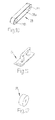
Die Erfindung mit ihren Merkmalen und Vorteilen wird nun anhand von beispielhaften Ausführungsformen unter Bezugnahme auf die Zeichnungen im Detail erläutert. In den Zeichnungen zeigen:
-
Fig. 1 bis Fig. 6 schematische perspektivische Ansichten von Teilen einer erfindungsgemäßen Vorrichtung zur Erläuterung des erfindungsgemäßen Verfahrens; -
Fig. 7A und Fig. 7B eine erste Ausführungsform eines Spreizwerkzeugs in der Perspektive und in Draufsicht; -
Fig. 8A und Fig. 8B eine zweite Ausführungsform eines Spreizwerkzeugs in der Perspektive und in Draufsicht; -
Fig. 9A und Fig. 9B eine dritte Ausführungsform eines Spreizwerkzeugs in der Perspektive und in Draufsicht; -
Fig. 10 eine perspektivische Teilansicht einer ersten Ausführungsform einer Anpresseinrichtung; -
Fig. 11 eine perspektivische Ansicht einer zweiten Ausführungsform einer Anpresseinrichtung; und -
Fig. 12 eine perspektivische Ansicht einer dritten Ausführungsform einer Anpresseinrichtung.
-
Fig. 1 to Fig. 6 schematic perspective views of parts of a device according to the invention for explaining the method according to the invention; -
FIGS. 7A and 7B a first embodiment of a spreading tool in perspective and in plan view; -
8A and 8B a second embodiment of a spreading tool in perspective and in plan view; -
Figs. 9A and 9B a third embodiment of a spreading tool in perspective and in plan view; -
Fig. 10 a partial perspective view of a first embodiment of a pressing device; -
Fig. 11 a perspective view of a second embodiment of a pressing device; and -
Fig. 12 a perspective view of a third embodiment of a pressing device.
Das erfindungsgemäße Verfahren zum Ausbilden eines offenen Bodens an einem offenen Endbereich eines schlauchförmigen Sackkörpers wird nun anhand der in
Die Bodenöffnungsvorrichtung 1 weist eine Transporteinrichtung 2 in Form eines Förderbands auf und bewegt sich kontinuierlich mit einer Transportgeschwindigkeit V in einer Transportrichtung T. Auf der Transporteinrichtung 2 liegen schlauchförmige Sackkörper 10 in flachliegendem Zustand mit ihrer Längserstreckung L quer zur Transportrichtung T. Die Sackkörper 10 werden auf dem Förderband durch nicht dargestellte Haltemittel gegen Verrutschen gesichert. Solche Haltemittel umfassen z.B. Leisten aus ferromagnetischem Material, die auf den Sackkörpern 10 platziert werden und von der Unterseite des Förderbands mit Magneten, die sich zusammen mit dem Förderband bewegen, gegen das Förderband angezogen werden und dabei den dazwischenliegenden Sackkörper 10 an das Förderband anpressen. Alternativ dazu ist das Förderband als Lochförderband ausgebildet, wobei von der Unterseite des Förderbands ein Vakuum angelegt wird, das den Sackkörper 10 an das Förderband ansaugt.The
Die schlauchförmigen Sackkörper 10 sind beispielweise aus Gewebe aus gereckten Kunststoffbändchen hergestellt. Die Kunststoffbändchen können ein Polyethylen- oder Polypropylen-Material umfassen. Optional weist das Gewebe eine Beschichtung aus Kunststoff auf. Die schlauchförmigen Sackkörper 10 können alternativ dazu aus Kunststofffolie hergestellt sein.The
Der schlauchförmige Sackkörper 10 weist zwei einander gegenüberliegende offene Endbereiche 10e, 10f auf. Der Endbereich 10e soll zu einem Kreuzboden geformt werden, wie nachfolgend erklärt wird. In weiterer Bearbeitung kann auch der Endbereich 10f auf die gleiche Weise wie der Endbereich 10e zu einem Kreuzboden geformt werden, wodurch ein Kastensack oder Kastenventilsack erzeugt wird.The
In
In
Aus
Nachdem der vordere dreieckige Eckumschlag 10j gebildet worden ist, wird das Spreizwerkzeug 21 durch relatives Verzögern seiner Bewegung gegenüber der Transportgeschwindigkeit T nach hinten aus dem vorderen Eckumschlag 10j herausbewegt, wobei es das Umklappen der Schlauchlagen 10a, 10b fortsetzt und somit die Bildung der Bodenseitenklappen 10u, 10t aus den beiden Schlauchlagen 10a, 10b fortschreitet. Bereits bevor sich das Spreizwerkzeug 21 aus dem vorderen Eckumschlag 10j zurückzieht, ist die Spitze 10s des vorderen Eckumschlags 10j zu einer Anpresseinrichtung 28 gelangt, die zunächst die Spitze 10s und sukzessive den gesamten vorderen Eckumschlag 10j in der definierten Form hält und verhindert, dass sich der Eckumschlag 10j wieder entfaltet. In dieser Ausführungsform ist die Anpresseinrichtung 28 als ein Anpressband 28a ausgebildet, das in Transportrichtung T ausgerichtet ist und um zwei Umlenkrollen 28b, 28c umläuft, von denen in
Der Begriff "relativ zur Transportgeschwindigkeit V verringerte oder negative Geschwindigkeit V2R", wie oben verwendet, bedeutet, dass das Spreizwerkzeug 21 zwar in Transportrichtung, aber mit geringerer Geschwindigkeit als die Transportgeschwindigkeit V bewegt wird, oder dass das Spreizwerkzeug vorübergehend angehalten wird, oder dass das Spreizwerkzeug entgegen der Transportrichtung T bewegt wird.The term "relative to the transport speed V reduced or negative speed V2R", as used above, means that the spreading
Wie in
Wie in
Claims (21)
das Einführen eines Spreizwerkzeugs (21, 30, 32) in den geöffneten Endbereich des schlauchförmigen Sackkörpers,
das Bewegen des Spreizwerkzeugs in Transportrichtung (T) mit einer relativ zur Transportgeschwindigkeit (T) erhöhten Geschwindigkeit (V1R), bis das Spreizwerkzeug (21) an dem - in Transportrichtung gesehen - vorderen Teil (10v) des geöffneten Endbereichs mit zumindest zwei am Spreizwerkzeug definierten vorderen Konturpunkten (23p, 24p; 33p, 34p) gegen die Innenseite des schlauchförmigen Sackkörpers aufläuft und dabei besagten vorderen Teil (10v) zu einem vorderen Eckumschlag (10j) in Gestalt eines im Wesentlichen gleichschenkeligen Dreiecks spreizt, wobei jeder Schenkel (10k, 10m) des vorderen dreieckigen Eckumschlags (10j) an zumindest einem vorderen Konturpunkt (23p, 24p; 33p, 34p) des Spreizwerkzeugs (21) anliegt,
das Herausbewegen des Spreizwerkzeugs (21) aus dem vorderen Eckumschlag (10j) durch relatives Verzögern seiner Bewegung gegenüber der Transportgeschwindigkeit (V), und
das Pressen des erzeugten vorderen Eckumschlags (10j).A method for forming an open bottom at an open end portion of a tubular bag body (10), which bag body is preferably made of a fabric of stretched plastic tape or a plastic film, wherein the bag body lying flat in a transport direction (T) transversely to its longitudinal extent (L) with transported a transport speed (V) and during the transport of the folding end portion (10e) of the tubular bag body is opened, characterized by
inserting a spreading tool (21, 30, 32) into the open end region of the tubular bag body,
moving the spreading tool in the transporting direction (T) at a speed (V1R) which is increased relative to the transporting speed (T), until the spreading tool (21) has the front part (10v) of the opened end region defined with at least two on the spreading tool, as seen in the direction of transport front contour points (23p, 24p, 33p, 34p) runs against the inside of the tubular bag body and thereby spreads said front part (10v) to a front corner envelope (10j) in the shape of a substantially isosceles triangle, each leg (10k, 10m) the front triangular corner turn (10j) abuts on at least one front contour point (23p, 24p; 33p, 34p) of the spreading tool (21),
moving the spreading tool (21) out of the front corner envelope (10j) by relatively delaying its movement relative to the transport speed (V), and
pressing the generated front corner envelope (10j).
das Herausbewegen des Spreizwerkzeugs (21, 30, 32) aus dem hinteren Eckumschlag (10p) durch relatives Beschleunigen seiner Bewegung gegenüber der Transportgeschwindigkeit (V), und
das Pressen des erzeugten hinteren Eckumschlags (10p).A method according to claim 1, characterized in that the spreading tool (21, 30, 32) in the open end region (10e) of the tubular bag body (10) in the transport direction (T) with a relative to the transport speed (V) reduced or negative speed (V2R) is moved until it reaches the - viewed in the direction of transport - the rear part (10h) of the open end portion and runs with at least two defined on Spreizwerkzeug rear contour points (23q, 24q, 33p, 34p) against the inside of the tubular bag body and thereby said rear part (10h) spreads to a trailing corner envelope (10p) in the shape of a substantially isosceles triangle, each leg (10q, 10r) of the trailing triangular end envelope (10p) at at least one trailing contour point (23q, 24q; 33p, 34p) of the spreading tool is applied,
moving the spreading tool (21, 30, 32) out of the rear corner envelope (10p) by relatively accelerating its movement relative to the transport speed (V), and
the pressing of the generated rear corner envelope (10p).
gekennzeichnet durch
ein Spreizwerkzeug (21, 30, 32), das in den geöffneten Endbereich (10e) eines jeden schlauchförmigen Sackkörpers während seines Transports auf der Transporteinrichtung einführbar ist,
wobei des Spreizwerkzeug (21, 30, 32) in Transportrichtung (T) mit einer relativ zur Transportgeschwindigkeit (V) erhöhten Geschwindigkeit (V1R) bewegbar ist, bis es den - in Transportrichtung gesehen - vorderen Teil (10v) des geöffneten Endbereichs erreicht und mit zumindest zwei am Spreizwerkzeug definierten vorderen Konturpunkten (23p, 24p; 33p, 34p) gegen die Innenseite des schlauchförmigen Sackkörpers aufläuft und dabei besagten vorderen Teil (10v) zu einem vorderen Eckumschlag (10j) in Gestalt eines im Wesentlichen gleichschenkeligen Dreiecks spreizt, wobei jeder Schenkel (10k, 10m) des vorderen dreieckigen Eckumschlags (10j) an zumindest einem vorderen Konturpunkt (23p, 24p; 33p, 34p) des Spreizwerkzeugs anliegt, und wobei das Spreizwerkzeug (21, 30, 32) aus dem vorderen Eckumschlag (10j) durch relatives Verzögern seiner Bewegung gegenüber der Transportgeschwindigkeit (V) herausbewegbar ist,
und eine Anpresseinrichtung (28, 35, 36) zum Pressen des erzeugten vorderen Eckumschlags.Device (1) for forming an open bottom at an open end region (10e) of a tubular bag body (10), which bag body is preferably made of a fabric of stretched plastic tape or plastic film, with a transport device (2) for transporting the bag bodies (10). in a flat state in a transport direction (T) transversely to its longitudinal extent (L) at a transport speed (V), and with opening means (20) for opening the end regions of the tubular bag bodies to be folded during their transport on the transport device,
marked by
a spreading tool (21, 30, 32) insertable into the open end portion (10e) of each tubular bag body during its transport on the transport means,
wherein the spreading tool (21, 30, 32) in the transport direction (T) with a relative to the transport speed (V) increased speed (V1R) is movable until it reaches - seen in the direction of transport - the front part (10v) of the open end portion and with at least two defined on the expansion tool front contour points (23p, 24p, 33p, 34p) runs against the inside of the tubular bag body and thereby said front part (10v) spreads to a front corner envelope (10j) in the form of a substantially isosceles triangle, each leg (10k, 10m) of the front triangular corner turn (10j) abuts on at least one front contour point (23p, 24p; 33p, 34p) of the expansion tool, and wherein the expansion tool (21, 30, 32) from the front corner turn (10j) by relative Delaying its movement relative to the transport speed (V) is moved out,
and a pressing device (28, 35, 36) for pressing the generated front corner envelope.
Priority Applications (9)
| Application Number | Priority Date | Filing Date | Title |
|---|---|---|---|
| ES10187549T ES2424952T3 (en) | 2010-10-14 | 2010-10-14 | Procedure and device for the configuration of open bottoms in final areas of tubular bag bodies |
| EP10187549.0A EP2441574B1 (en) | 2010-10-14 | 2010-10-14 | Method and device for constructing open bases at end sections of tubular bag bodies |
| RU2013121833/12A RU2543423C2 (en) | 2010-10-14 | 2011-10-04 | Method and device for formation of open bottom in end zones of hose housings of bags |
| CN201180049808.3A CN103153599B (en) | 2010-10-14 | 2011-10-04 | Method and device for forming open bottoms on end regions of tubular bag bodies |
| BR112013009006-5A BR112013009006B1 (en) | 2010-10-14 | 2011-10-04 | METHODS AND DEVICE FOR FORMING OPEN FUNDS IN END REGIONS OF TUBULAR BAG BODIES |
| MX2013003146A MX2013003146A (en) | 2010-10-14 | 2011-10-04 | Method and device for forming open bottoms on end regions of tubular bag bodies. |
| PCT/EP2011/067329 WO2012049040A1 (en) | 2010-10-14 | 2011-10-04 | Method and device for forming open bottoms on end regions of tubular bag bodies |
| MYPI2013000880A MY155933A (en) | 2010-10-14 | 2011-10-04 | Method and device for forming open bottoms at end regions of tubular bag bodies |
| ZA2013/01974A ZA201301974B (en) | 2010-10-14 | 2013-03-15 | Method and device for forming open bottoms on and regions of tubular bag bodies |
Applications Claiming Priority (1)
| Application Number | Priority Date | Filing Date | Title |
|---|---|---|---|
| EP10187549.0A EP2441574B1 (en) | 2010-10-14 | 2010-10-14 | Method and device for constructing open bases at end sections of tubular bag bodies |
Publications (2)
| Publication Number | Publication Date |
|---|---|
| EP2441574A1 true EP2441574A1 (en) | 2012-04-18 |
| EP2441574B1 EP2441574B1 (en) | 2013-05-15 |
Family
ID=43663517
Family Applications (1)
| Application Number | Title | Priority Date | Filing Date |
|---|---|---|---|
| EP10187549.0A Active EP2441574B1 (en) | 2010-10-14 | 2010-10-14 | Method and device for constructing open bases at end sections of tubular bag bodies |
Country Status (9)
| Country | Link |
|---|---|
| EP (1) | EP2441574B1 (en) |
| CN (1) | CN103153599B (en) |
| BR (1) | BR112013009006B1 (en) |
| ES (1) | ES2424952T3 (en) |
| MX (1) | MX2013003146A (en) |
| MY (1) | MY155933A (en) |
| RU (1) | RU2543423C2 (en) |
| WO (1) | WO2012049040A1 (en) |
| ZA (1) | ZA201301974B (en) |
Cited By (7)
| Publication number | Priority date | Publication date | Assignee | Title |
|---|---|---|---|---|
| EP2711165A1 (en) | 2012-09-24 | 2014-03-26 | Starlinger & Co. Gesellschaft m.b.H. | Conveyor device for sack bodies |
| EP2711164A1 (en) | 2012-09-24 | 2014-03-26 | Starlinger & Co. Gesellschaft m.b.H. | Apparatus and method for opening an end area of a tubular sack body |
| WO2015032485A1 (en) * | 2013-09-04 | 2015-03-12 | Windmöller & Hölscher Kg | Apparatus for producing bags |
| WO2017191190A1 (en) * | 2016-05-03 | 2017-11-09 | Windmöller & Hölscher Kg | Transport device and method for transporting sacks or bags, and device for producing sacks or bags |
| JP2019521049A (en) * | 2016-07-14 | 2019-07-25 | スターリンガー アンド コー ゲゼルシャフト エム.ベー.ハー. | Device for opening the end area of a tubular bag |
| WO2022226556A1 (en) | 2021-04-29 | 2022-11-03 | Starlinger & Co Gesellschaft M.B.H. | Device and method for producing bags from tubular pieces |
| US11524815B2 (en) | 2017-12-14 | 2022-12-13 | Starlinger & Co Gesellschaft M.B.H. | Bag for loose material |
Families Citing this family (9)
| Publication number | Priority date | Publication date | Assignee | Title |
|---|---|---|---|---|
| AT515831B1 (en) | 2014-05-20 | 2016-07-15 | Lohia Corp Ltd | Apparatus and method for forming a bottom opening |
| AT515832B1 (en) | 2014-05-20 | 2016-05-15 | Lohia Corp Ltd | Apparatus and method for forming a bottom opening between bag sections |
| EP3017940B1 (en) | 2014-11-04 | 2017-09-13 | Starlinger & Co. Gesellschaft m.b.H. | Method and a device for the production of bags from tubular bag bodies |
| CN108136708B (en) * | 2015-07-31 | 2020-12-15 | 温德莫勒及霍尔希尔公司 | Device and method for fixing an open bottom of a hose |
| CN105150589B (en) * | 2015-09-15 | 2018-09-21 | 无锡鼎茂机械制造有限公司 | Bag Making Machine is with turning over all over film pressing device |
| CN109703102B (en) * | 2019-01-16 | 2021-01-05 | 青岛晨峰智能装备有限公司 | Packaging bag bottom opening assembly, four-corner forming device and control method thereof |
| CN110385891B (en) * | 2019-07-04 | 2021-07-20 | 河北盛世锦唐包装有限公司 | Novel square-bottom valve bag making machine |
| CN115335216A (en) | 2020-01-29 | 2022-11-11 | 温德莫勒及霍尔希尔公司 | Device for producing corner folds in tubular bags |
| CN115697686A (en) * | 2020-05-11 | 2023-02-03 | 洛希亚有限公司 | Apparatus and method for opening the ends of tubular fabric articles to make square-bottomed bags |
Citations (9)
| Publication number | Priority date | Publication date | Assignee | Title |
|---|---|---|---|---|
| US2712275A (en) * | 1952-07-11 | 1955-07-05 | St Regis Paper Co | Bag bottom shaping device |
| DE1232812B (en) * | 1961-03-20 | 1967-01-19 | Windmoeller & Hoelscher | Device for forming and aligning the corners of open cross floors on cross-conveyed hose sections |
| DE1561473B1 (en) * | 1967-06-19 | 1971-08-26 | Windmoeller & Hoelscher | Device for raising and flattening cross bottoms on transversely conveyed plastic hose sections |
| DE2055016A1 (en) * | 1970-11-09 | 1972-05-25 | Windmöller & Hölscher, 4540 Lengerich | Method and device for the gas-tight gluing of the cross-bottom folds of sacks and bags |
| US3803989A (en) * | 1970-12-21 | 1974-04-16 | Windmoeller & Hoelscher | Apparatus for forming cross-bottom folding in bag manufacture |
| AT406755B (en) | 1998-10-05 | 2000-08-25 | Starlinger & Co Gmbh | DEVICE FOR OPENING TUBULAR BAG BODIES |
| AT407236B (en) | 1998-10-05 | 2001-01-25 | Starlinger & Co Gmbh | DEVICE FOR SEPARATING MATERIAL LAYERS |
| AT408427B (en) | 1995-01-25 | 2001-11-26 | Windmoeller & Hoelscher | DEVICE FOR PRODUCING CROSS-BODY BAGS |
| DE102008017442A1 (en) | 2008-04-03 | 2009-10-08 | Windmöller & Hölscher Kg | Fabric bag manufacturing device, has opening mechanism including material layer separating and folding unit for separating and folding material layers, which are foldable away from each other, so that bottom lies in plane of tube pieces |
Family Cites Families (7)
| Publication number | Priority date | Publication date | Assignee | Title |
|---|---|---|---|---|
| GB1242993A (en) * | 1969-02-07 | 1971-08-18 | Windmoeller & Hoelscher | Making flat bags from thermoplastic film |
| DE3530742A1 (en) * | 1985-08-28 | 1987-03-12 | Windmoeller & Hoelscher | DEVICE FOR UNLOCKING HOSE SECTIONS FOR BOTTOMING BAGS AND FOR WELDING BOTTOM SEAMS |
| US6042526A (en) * | 1995-06-20 | 2000-03-28 | B + B Maschinenbau Gmbh | Method of and apparatus for making a bottom of a tubular section for formation of a bag or sack |
| JP3619208B2 (en) * | 2002-04-26 | 2005-02-09 | トタニ技研工業株式会社 | Bottom material folding mechanism of bag making machine |
| CN2834895Y (en) * | 2005-09-07 | 2006-11-08 | 闻德华 | Automatic hand bag forming machine |
| DE102008017445A1 (en) * | 2008-04-03 | 2009-10-15 | Windmöller & Hölscher Kg | Apparatus and method for producing sacks |
| DE102008043758A1 (en) * | 2008-11-14 | 2010-12-16 | Windmöller & Hölscher Kg | Apparatus and method for producing sacks of pieces of hose, which preferably comprise woven fabric of stretched plastic tapes and consist of two superimposed walls |
-
2010
- 2010-10-14 ES ES10187549T patent/ES2424952T3/en active Active
- 2010-10-14 EP EP10187549.0A patent/EP2441574B1/en active Active
-
2011
- 2011-10-04 BR BR112013009006-5A patent/BR112013009006B1/en active IP Right Grant
- 2011-10-04 MX MX2013003146A patent/MX2013003146A/en active IP Right Grant
- 2011-10-04 RU RU2013121833/12A patent/RU2543423C2/en active
- 2011-10-04 MY MYPI2013000880A patent/MY155933A/en unknown
- 2011-10-04 WO PCT/EP2011/067329 patent/WO2012049040A1/en active Application Filing
- 2011-10-04 CN CN201180049808.3A patent/CN103153599B/en active Active
-
2013
- 2013-03-15 ZA ZA2013/01974A patent/ZA201301974B/en unknown
Patent Citations (9)
| Publication number | Priority date | Publication date | Assignee | Title |
|---|---|---|---|---|
| US2712275A (en) * | 1952-07-11 | 1955-07-05 | St Regis Paper Co | Bag bottom shaping device |
| DE1232812B (en) * | 1961-03-20 | 1967-01-19 | Windmoeller & Hoelscher | Device for forming and aligning the corners of open cross floors on cross-conveyed hose sections |
| DE1561473B1 (en) * | 1967-06-19 | 1971-08-26 | Windmoeller & Hoelscher | Device for raising and flattening cross bottoms on transversely conveyed plastic hose sections |
| DE2055016A1 (en) * | 1970-11-09 | 1972-05-25 | Windmöller & Hölscher, 4540 Lengerich | Method and device for the gas-tight gluing of the cross-bottom folds of sacks and bags |
| US3803989A (en) * | 1970-12-21 | 1974-04-16 | Windmoeller & Hoelscher | Apparatus for forming cross-bottom folding in bag manufacture |
| AT408427B (en) | 1995-01-25 | 2001-11-26 | Windmoeller & Hoelscher | DEVICE FOR PRODUCING CROSS-BODY BAGS |
| AT406755B (en) | 1998-10-05 | 2000-08-25 | Starlinger & Co Gmbh | DEVICE FOR OPENING TUBULAR BAG BODIES |
| AT407236B (en) | 1998-10-05 | 2001-01-25 | Starlinger & Co Gmbh | DEVICE FOR SEPARATING MATERIAL LAYERS |
| DE102008017442A1 (en) | 2008-04-03 | 2009-10-08 | Windmöller & Hölscher Kg | Fabric bag manufacturing device, has opening mechanism including material layer separating and folding unit for separating and folding material layers, which are foldable away from each other, so that bottom lies in plane of tube pieces |
Cited By (10)
| Publication number | Priority date | Publication date | Assignee | Title |
|---|---|---|---|---|
| EP2711165A1 (en) | 2012-09-24 | 2014-03-26 | Starlinger & Co. Gesellschaft m.b.H. | Conveyor device for sack bodies |
| EP2711164A1 (en) | 2012-09-24 | 2014-03-26 | Starlinger & Co. Gesellschaft m.b.H. | Apparatus and method for opening an end area of a tubular sack body |
| WO2014044534A1 (en) * | 2012-09-24 | 2014-03-27 | Starlinger & Co Gesellschaft M.B.H. | Conveying device for bag bodies |
| WO2015032485A1 (en) * | 2013-09-04 | 2015-03-12 | Windmöller & Hölscher Kg | Apparatus for producing bags |
| CN105722673A (en) * | 2013-09-04 | 2016-06-29 | 温德默乐与霍尔舍公司 | Apparatus for producing bags |
| CN105722673B (en) * | 2013-09-04 | 2019-05-21 | 温德默乐与霍尔舍公司 | Equipment for manufacturing bag |
| WO2017191190A1 (en) * | 2016-05-03 | 2017-11-09 | Windmöller & Hölscher Kg | Transport device and method for transporting sacks or bags, and device for producing sacks or bags |
| JP2019521049A (en) * | 2016-07-14 | 2019-07-25 | スターリンガー アンド コー ゲゼルシャフト エム.ベー.ハー. | Device for opening the end area of a tubular bag |
| US11524815B2 (en) | 2017-12-14 | 2022-12-13 | Starlinger & Co Gesellschaft M.B.H. | Bag for loose material |
| WO2022226556A1 (en) | 2021-04-29 | 2022-11-03 | Starlinger & Co Gesellschaft M.B.H. | Device and method for producing bags from tubular pieces |
Also Published As
| Publication number | Publication date |
|---|---|
| ES2424952T3 (en) | 2013-10-10 |
| CN103153599A (en) | 2013-06-12 |
| RU2543423C2 (en) | 2015-02-27 |
| RU2013121833A (en) | 2014-11-20 |
| ZA201301974B (en) | 2013-11-27 |
| MX2013003146A (en) | 2013-06-07 |
| EP2441574B1 (en) | 2013-05-15 |
| BR112013009006B1 (en) | 2020-12-15 |
| BR112013009006A2 (en) | 2016-07-05 |
| WO2012049040A1 (en) | 2012-04-19 |
| MY155933A (en) | 2015-12-31 |
| CN103153599B (en) | 2015-06-17 |
Similar Documents
| Publication | Publication Date | Title |
|---|---|---|
| EP2441574B1 (en) | Method and device for constructing open bases at end sections of tubular bag bodies | |
| EP2276628B1 (en) | Device and method for producing bags | |
| DE10002545A1 (en) | Method and device for producing packaging bags, envelopes and the like | |
| EP3017940B1 (en) | Method and a device for the production of bags from tubular bag bodies | |
| DE19522619C2 (en) | Process for the production of bottom bags with an internal bar | |
| AT506551B1 (en) | DEVICE AND METHOD FOR PRODUCING SAWS CONSISTING OF FABRICS OF ROLLED PLASTIC BELTS | |
| DE102009000893A1 (en) | Method and device for transporting flat workpieces | |
| EP2532513A2 (en) | Bag for tobacco and method and device for producing same | |
| DE102017119296A1 (en) | Packaging plant and method for packaging objects | |
| AT515831B1 (en) | Apparatus and method for forming a bottom opening | |
| DE2228808C2 (en) | Multiple folding device | |
| EP2346676B1 (en) | Device and a method for processing semifinished bag products, and gluing station for semifinished bag products | |
| DE102008017443B4 (en) | Apparatus and method for the production of sacks from pieces of hose | |
| EP2711164B1 (en) | Apparatus and method for opening an end area of a tubular sack body | |
| WO2010015505A1 (en) | In-line slide for opening ends of hose pieces | |
| DE19611740C2 (en) | Method and device for packaging packaged goods in a packaging bag with a reclosable flap | |
| EP3532271B1 (en) | Improvement in flap bag production | |
| WO2014044534A1 (en) | Conveying device for bag bodies | |
| EP1462240A2 (en) | Method of applying a reinforcing bands to a film | |
| DE102004022291B4 (en) | System for the production of sacks | |
| DE2310160A1 (en) | PROCESS AND MACHINE FOR MANUFACTURING VACUUM CLEANER INSERT BAGS | |
| DE2055016C3 (en) | Method for producing a gas-tight gluing of the bottom side covers of a cross bottom fold with the corner folds and devices for carrying out the method | |
| EP3851271A1 (en) | Method and device for the production of individual inner tubes and inner tubes and bags | |
| DE102008053280A1 (en) | Device for subsequent processing of semifinished products, particularly bottom laying device for cross bottom valve sacks, has gluing station with glue application head | |
| DE102006002787B3 (en) | Envelope made of two layers of paper, comprises adhesive areas arranged in L-shape in order to allow creation of curved outer contours |
Legal Events
| Date | Code | Title | Description |
|---|---|---|---|
| PUAI | Public reference made under article 153(3) epc to a published international application that has entered the european phase |
Free format text: ORIGINAL CODE: 0009012 |
|
| AK | Designated contracting states |
Kind code of ref document: A1 Designated state(s): AL AT BE BG CH CY CZ DE DK EE ES FI FR GB GR HR HU IE IS IT LI LT LU LV MC MK MT NL NO PL PT RO RS SE SI SK SM TR |
|
| AX | Request for extension of the european patent |
Extension state: BA ME |
|
| 17P | Request for examination filed |
Effective date: 20121017 |
|
| GRAP | Despatch of communication of intention to grant a patent |
Free format text: ORIGINAL CODE: EPIDOSNIGR1 |
|
| GRAS | Grant fee paid |
Free format text: ORIGINAL CODE: EPIDOSNIGR3 |
|
| GRAA | (expected) grant |
Free format text: ORIGINAL CODE: 0009210 |
|
| AK | Designated contracting states |
Kind code of ref document: B1 Designated state(s): AL AT BE BG CH CY CZ DE DK EE ES FI FR GB GR HR HU IE IS IT LI LT LU LV MC MK MT NL NO PL PT RO RS SE SI SK SM TR |
|
| REG | Reference to a national code |
Ref country code: GB Ref legal event code: FG4D Free format text: NOT ENGLISH Ref country code: CH Ref legal event code: EP |
|
| REG | Reference to a national code |
Ref country code: AT Ref legal event code: REF Ref document number: 611905 Country of ref document: AT Kind code of ref document: T Effective date: 20130615 |
|
| REG | Reference to a national code |
Ref country code: IE Ref legal event code: FG4D Free format text: LANGUAGE OF EP DOCUMENT: GERMAN |
|
| REG | Reference to a national code |
Ref country code: DE Ref legal event code: R096 Ref document number: 502010003338 Country of ref document: DE Effective date: 20130718 |
|
| REG | Reference to a national code |
Ref country code: ES Ref legal event code: FG2A Ref document number: 2424952 Country of ref document: ES Kind code of ref document: T3 Effective date: 20131010 |
|
| REG | Reference to a national code |
Ref country code: LT Ref legal event code: MG4D |
|
| REG | Reference to a national code |
Ref country code: NL Ref legal event code: VDEP Effective date: 20130515 |
|
| PG25 | Lapsed in a contracting state [announced via postgrant information from national office to epo] |
Ref country code: NO Free format text: LAPSE BECAUSE OF FAILURE TO SUBMIT A TRANSLATION OF THE DESCRIPTION OR TO PAY THE FEE WITHIN THE PRESCRIBED TIME-LIMIT Effective date: 20130815 Ref country code: FI Free format text: LAPSE BECAUSE OF FAILURE TO SUBMIT A TRANSLATION OF THE DESCRIPTION OR TO PAY THE FEE WITHIN THE PRESCRIBED TIME-LIMIT Effective date: 20130515 Ref country code: IS Free format text: LAPSE BECAUSE OF FAILURE TO SUBMIT A TRANSLATION OF THE DESCRIPTION OR TO PAY THE FEE WITHIN THE PRESCRIBED TIME-LIMIT Effective date: 20130915 Ref country code: SE Free format text: LAPSE BECAUSE OF FAILURE TO SUBMIT A TRANSLATION OF THE DESCRIPTION OR TO PAY THE FEE WITHIN THE PRESCRIBED TIME-LIMIT Effective date: 20130515 Ref country code: GR Free format text: LAPSE BECAUSE OF FAILURE TO SUBMIT A TRANSLATION OF THE DESCRIPTION OR TO PAY THE FEE WITHIN THE PRESCRIBED TIME-LIMIT Effective date: 20130816 Ref country code: PT Free format text: LAPSE BECAUSE OF FAILURE TO SUBMIT A TRANSLATION OF THE DESCRIPTION OR TO PAY THE FEE WITHIN THE PRESCRIBED TIME-LIMIT Effective date: 20130916 Ref country code: LT Free format text: LAPSE BECAUSE OF FAILURE TO SUBMIT A TRANSLATION OF THE DESCRIPTION OR TO PAY THE FEE WITHIN THE PRESCRIBED TIME-LIMIT Effective date: 20130515 Ref country code: SI Free format text: LAPSE BECAUSE OF FAILURE TO SUBMIT A TRANSLATION OF THE DESCRIPTION OR TO PAY THE FEE WITHIN THE PRESCRIBED TIME-LIMIT Effective date: 20130515 |
|
| PG25 | Lapsed in a contracting state [announced via postgrant information from national office to epo] |
Ref country code: HR Free format text: LAPSE BECAUSE OF FAILURE TO SUBMIT A TRANSLATION OF THE DESCRIPTION OR TO PAY THE FEE WITHIN THE PRESCRIBED TIME-LIMIT Effective date: 20130515 Ref country code: BG Free format text: LAPSE BECAUSE OF FAILURE TO SUBMIT A TRANSLATION OF THE DESCRIPTION OR TO PAY THE FEE WITHIN THE PRESCRIBED TIME-LIMIT Effective date: 20130815 Ref country code: RS Free format text: LAPSE BECAUSE OF FAILURE TO SUBMIT A TRANSLATION OF THE DESCRIPTION OR TO PAY THE FEE WITHIN THE PRESCRIBED TIME-LIMIT Effective date: 20130515 Ref country code: PL Free format text: LAPSE BECAUSE OF FAILURE TO SUBMIT A TRANSLATION OF THE DESCRIPTION OR TO PAY THE FEE WITHIN THE PRESCRIBED TIME-LIMIT Effective date: 20130515 |
|
| PG25 | Lapsed in a contracting state [announced via postgrant information from national office to epo] |
Ref country code: LV Free format text: LAPSE BECAUSE OF FAILURE TO SUBMIT A TRANSLATION OF THE DESCRIPTION OR TO PAY THE FEE WITHIN THE PRESCRIBED TIME-LIMIT Effective date: 20130515 |
|
| PG25 | Lapsed in a contracting state [announced via postgrant information from national office to epo] |
Ref country code: DK Free format text: LAPSE BECAUSE OF FAILURE TO SUBMIT A TRANSLATION OF THE DESCRIPTION OR TO PAY THE FEE WITHIN THE PRESCRIBED TIME-LIMIT Effective date: 20130515 Ref country code: SK Free format text: LAPSE BECAUSE OF FAILURE TO SUBMIT A TRANSLATION OF THE DESCRIPTION OR TO PAY THE FEE WITHIN THE PRESCRIBED TIME-LIMIT Effective date: 20130515 Ref country code: EE Free format text: LAPSE BECAUSE OF FAILURE TO SUBMIT A TRANSLATION OF THE DESCRIPTION OR TO PAY THE FEE WITHIN THE PRESCRIBED TIME-LIMIT Effective date: 20130515 |
|
| PG25 | Lapsed in a contracting state [announced via postgrant information from national office to epo] |
Ref country code: IT Free format text: LAPSE BECAUSE OF FAILURE TO SUBMIT A TRANSLATION OF THE DESCRIPTION OR TO PAY THE FEE WITHIN THE PRESCRIBED TIME-LIMIT Effective date: 20130515 Ref country code: NL Free format text: LAPSE BECAUSE OF FAILURE TO SUBMIT A TRANSLATION OF THE DESCRIPTION OR TO PAY THE FEE WITHIN THE PRESCRIBED TIME-LIMIT Effective date: 20130515 Ref country code: RO Free format text: LAPSE BECAUSE OF FAILURE TO SUBMIT A TRANSLATION OF THE DESCRIPTION OR TO PAY THE FEE WITHIN THE PRESCRIBED TIME-LIMIT Effective date: 20130515 |
|
| PLBE | No opposition filed within time limit |
Free format text: ORIGINAL CODE: 0009261 |
|
| STAA | Information on the status of an ep patent application or granted ep patent |
Free format text: STATUS: NO OPPOSITION FILED WITHIN TIME LIMIT |
|
| 26N | No opposition filed |
Effective date: 20140218 |
|
| BERE | Be: lapsed |
Owner name: STARLINGER & CO -G. M.B.H. Effective date: 20131031 |
|
| REG | Reference to a national code |
Ref country code: DE Ref legal event code: R097 Ref document number: 502010003338 Country of ref document: DE Effective date: 20140218 |
|
| PG25 | Lapsed in a contracting state [announced via postgrant information from national office to epo] |
Ref country code: MC Free format text: LAPSE BECAUSE OF FAILURE TO SUBMIT A TRANSLATION OF THE DESCRIPTION OR TO PAY THE FEE WITHIN THE PRESCRIBED TIME-LIMIT Effective date: 20130515 |
|
| REG | Reference to a national code |
Ref country code: IE Ref legal event code: MM4A |
|
| REG | Reference to a national code |
Ref country code: FR Ref legal event code: ST Effective date: 20140630 |
|
| PG25 | Lapsed in a contracting state [announced via postgrant information from national office to epo] |
Ref country code: FR Free format text: LAPSE BECAUSE OF NON-PAYMENT OF DUE FEES Effective date: 20131031 |
|
| PG25 | Lapsed in a contracting state [announced via postgrant information from national office to epo] |
Ref country code: BE Free format text: LAPSE BECAUSE OF NON-PAYMENT OF DUE FEES Effective date: 20131031 |
|
| PG25 | Lapsed in a contracting state [announced via postgrant information from national office to epo] |
Ref country code: IE Free format text: LAPSE BECAUSE OF NON-PAYMENT OF DUE FEES Effective date: 20131014 |
|
| PG25 | Lapsed in a contracting state [announced via postgrant information from national office to epo] |
Ref country code: SM Free format text: LAPSE BECAUSE OF FAILURE TO SUBMIT A TRANSLATION OF THE DESCRIPTION OR TO PAY THE FEE WITHIN THE PRESCRIBED TIME-LIMIT Effective date: 20130515 |
|
| REG | Reference to a national code |
Ref country code: CH Ref legal event code: PL |
|
| GBPC | Gb: european patent ceased through non-payment of renewal fee |
Effective date: 20141014 |
|
| PG25 | Lapsed in a contracting state [announced via postgrant information from national office to epo] |
Ref country code: CY Free format text: LAPSE BECAUSE OF FAILURE TO SUBMIT A TRANSLATION OF THE DESCRIPTION OR TO PAY THE FEE WITHIN THE PRESCRIBED TIME-LIMIT Effective date: 20130515 |
|
| PG25 | Lapsed in a contracting state [announced via postgrant information from national office to epo] |
Ref country code: LI Free format text: LAPSE BECAUSE OF NON-PAYMENT OF DUE FEES Effective date: 20141031 Ref country code: MK Free format text: LAPSE BECAUSE OF FAILURE TO SUBMIT A TRANSLATION OF THE DESCRIPTION OR TO PAY THE FEE WITHIN THE PRESCRIBED TIME-LIMIT Effective date: 20130515 Ref country code: GB Free format text: LAPSE BECAUSE OF NON-PAYMENT OF DUE FEES Effective date: 20141014 Ref country code: CH Free format text: LAPSE BECAUSE OF NON-PAYMENT OF DUE FEES Effective date: 20141031 Ref country code: LU Free format text: LAPSE BECAUSE OF NON-PAYMENT OF DUE FEES Effective date: 20131014 Ref country code: HU Free format text: LAPSE BECAUSE OF FAILURE TO SUBMIT A TRANSLATION OF THE DESCRIPTION OR TO PAY THE FEE WITHIN THE PRESCRIBED TIME-LIMIT; INVALID AB INITIO Effective date: 20101014 |
|
| PG25 | Lapsed in a contracting state [announced via postgrant information from national office to epo] |
Ref country code: MT Free format text: LAPSE BECAUSE OF FAILURE TO SUBMIT A TRANSLATION OF THE DESCRIPTION OR TO PAY THE FEE WITHIN THE PRESCRIBED TIME-LIMIT Effective date: 20130515 |
|
| REG | Reference to a national code |
Ref country code: DE Ref legal event code: R079 Ref document number: 502010003338 Country of ref document: DE Free format text: PREVIOUS MAIN CLASS: B31B0029000000 Ipc: B31B0070000000 |
|
| PG25 | Lapsed in a contracting state [announced via postgrant information from national office to epo] |
Ref country code: AL Free format text: LAPSE BECAUSE OF FAILURE TO SUBMIT A TRANSLATION OF THE DESCRIPTION OR TO PAY THE FEE WITHIN THE PRESCRIBED TIME-LIMIT Effective date: 20130515 |
|
| P01 | Opt-out of the competence of the unified patent court (upc) registered |
Effective date: 20230526 |
|
| PGFP | Annual fee paid to national office [announced via postgrant information from national office to epo] |
Ref country code: ES Payment date: 20231117 Year of fee payment: 14 |
|
| PGFP | Annual fee paid to national office [announced via postgrant information from national office to epo] |
Ref country code: TR Payment date: 20231005 Year of fee payment: 14 Ref country code: DE Payment date: 20231018 Year of fee payment: 14 Ref country code: CZ Payment date: 20231002 Year of fee payment: 14 Ref country code: AT Payment date: 20231019 Year of fee payment: 14 |