EP2439499A1 - Sensor structure - Google Patents
Sensor structure Download PDFInfo
- Publication number
- EP2439499A1 EP2439499A1 EP20110184258 EP11184258A EP2439499A1 EP 2439499 A1 EP2439499 A1 EP 2439499A1 EP 20110184258 EP20110184258 EP 20110184258 EP 11184258 A EP11184258 A EP 11184258A EP 2439499 A1 EP2439499 A1 EP 2439499A1
- Authority
- EP
- European Patent Office
- Prior art keywords
- air
- housing
- airflow
- sensing element
- sensor structure
- Prior art date
- Legal status (The legal status is an assumption and is not a legal conclusion. Google has not performed a legal analysis and makes no representation as to the accuracy of the status listed.)
- Withdrawn
Links
Images


Classifications
-
- F—MECHANICAL ENGINEERING; LIGHTING; HEATING; WEAPONS; BLASTING
- F02—COMBUSTION ENGINES; HOT-GAS OR COMBUSTION-PRODUCT ENGINE PLANTS
- F02M—SUPPLYING COMBUSTION ENGINES IN GENERAL WITH COMBUSTIBLE MIXTURES OR CONSTITUENTS THEREOF
- F02M35/00—Combustion-air cleaners, air intakes, intake silencers, or induction systems specially adapted for, or arranged on, internal-combustion engines
- F02M35/10—Air intakes; Induction systems
- F02M35/10373—Sensors for intake systems
- F02M35/10393—Sensors for intake systems for characterising a multi-component mixture, e.g. for the composition such as humidity, density or viscosity
-
- G—PHYSICS
- G01—MEASURING; TESTING
- G01F—MEASURING VOLUME, VOLUME FLOW, MASS FLOW OR LIQUID LEVEL; METERING BY VOLUME
- G01F1/00—Measuring the volume flow or mass flow of fluid or fluent solid material wherein the fluid passes through a meter in a continuous flow
- G01F1/68—Measuring the volume flow or mass flow of fluid or fluent solid material wherein the fluid passes through a meter in a continuous flow by using thermal effects
- G01F1/684—Structural arrangements; Mounting of elements, e.g. in relation to fluid flow
-
- G—PHYSICS
- G01—MEASURING; TESTING
- G01F—MEASURING VOLUME, VOLUME FLOW, MASS FLOW OR LIQUID LEVEL; METERING BY VOLUME
- G01F5/00—Measuring a proportion of the volume flow
-
- F—MECHANICAL ENGINEERING; LIGHTING; HEATING; WEAPONS; BLASTING
- F02—COMBUSTION ENGINES; HOT-GAS OR COMBUSTION-PRODUCT ENGINE PLANTS
- F02M—SUPPLYING COMBUSTION ENGINES IN GENERAL WITH COMBUSTIBLE MIXTURES OR CONSTITUENTS THEREOF
- F02M35/00—Combustion-air cleaners, air intakes, intake silencers, or induction systems specially adapted for, or arranged on, internal-combustion engines
- F02M35/10—Air intakes; Induction systems
- F02M35/10373—Sensors for intake systems
- F02M35/1038—Sensors for intake systems for temperature or pressure
-
- F—MECHANICAL ENGINEERING; LIGHTING; HEATING; WEAPONS; BLASTING
- F02—COMBUSTION ENGINES; HOT-GAS OR COMBUSTION-PRODUCT ENGINE PLANTS
- F02M—SUPPLYING COMBUSTION ENGINES IN GENERAL WITH COMBUSTIBLE MIXTURES OR CONSTITUENTS THEREOF
- F02M35/00—Combustion-air cleaners, air intakes, intake silencers, or induction systems specially adapted for, or arranged on, internal-combustion engines
- F02M35/10—Air intakes; Induction systems
- F02M35/10373—Sensors for intake systems
- F02M35/10386—Sensors for intake systems for flow rate
Definitions
- the present invention relates to a sensor structure suitable for physical quantity measurement relating to intake air in an internal combustion engine, and an internal combustion engine control device that uses the sensor structure.
- a heating resistor type mass air flow measurement device relating to a flow measuring technique for example, is known as a physical quantity measuring technique relating to intake air for internal combustion engines.
- the heating resistor type mass air flow measurement device utilizes the correlation of the quantity of heat taken from a heating resistor with inflow discharge.
- the heating resistor type mass air flow measurement device is capable of directly measuring mass flow required to control combustion in an engine and is thus widely used as a flowmeter for air-fuel ratio control particularly in an automobile.
- JP Patent Publication (Kokai) No. 2010-043883 A describes a sensor including a flow measurement device, a pressure detecting device, a humidity detecting device, and the like in an integrated manner, the sensor having a function of measuring a plurality of physical quantities.
- Automobiles that use an electronically-controlled fuel injection system have been common and become more sophisticated in performance and function in recent years.
- an engine room is internally crammed with various sensors and control instruments.
- a wire harness that interconnects various sensors and control instruments as well as a control unit configured to control the sensors and control instruments, for example, is complicatedly intricate.
- the above-described flow measurement device is integrated with a temperature detecting device and even a semiconductor pressure detecting device, a humidity detecting device, and the like to allow connectors to be shared. This enables a reduction in the number of steps required to assemble components together into a vehicle and simplification of the wire harness.
- the heating resistor type mass air flow measurement device is integrated with a temperature detecting device.
- heating resistor type mass air flow measurement devices are integrated with the above-described pressure detecting device and humidity detecting device in the future, various technical problems are expected to occur.
- a humidity sensor part In order to improve the measurement precision and measurement responsiveness of the humidity sensor when an intake air humidity is measured, it is advisable to expose a humidity sensor part directly to an air flow.
- JP Patent Publication (Kokai) No. 2010-043883 A if a main air flow in an airflow tube exists near an air inlet port and part of the main flow is introduced into the humidity sensor part, polluting substances floating in the air are highly likely to be taken in together. Accordingly, a first problem to be solved by the present invention is how to generate an air flow necessary for a humidity sensor part in a state where an air inlet port to the humidity sensor part is provided in a portion where an air flow does not exist.
- a second problem to be solved by the present invention is how to prevent interference in performance and structure due to an integrated structure of various sensors.
- JP Patent Publication (Kokai) No. 2010-043883 A for example, if a secondary air flow passage for an airflow sensor and a secondary air flow passage for a humidity sensor are connected to each other, a flow of air to be supplied to the airflow sensor is disturbed by air flow separation and joining, and a quantity of air to be supplied is fluctuated thereby.
- a burr and the like occurring at the time of mold forming remain in a connection part between the secondary air flow passages, the quantity and disturbance of air do not become uniform, resulting in fluctuations in measurement precision of both the sensors.
- a third problem to be solved by the present invention is how to improve simplicity in manufacture and ease in achievement of an integrated structure.
- JP Patent Publication (Kokai) No. 2010-043883 A for example, if an air intake channel leading to the humidity sensor part is configured to be long, polluting substances are less likely to reach the humidity sensor part, but difficulty in manufacture concerning dimension stability and the like needs to be solved.
- the present invention has been made in view of the above-mentioned problems, and therefore has an object to provide a sensor structure that is excellent in resistance to pollution, has high precision and high quality, and facilitates integration and manufacture.
- a sensor structure including: a housing including a connector that mediates an input/output exchange with an outside and a terminal of the connector; and/or an electronic circuit board that is mounted inside of the housing and includes a humidity sensing element, the terminal of the connector and the electronic circuit board being electrically connected to each other, the sensor structure being inserted to be attached to an airflow tube through which a main air flows, via a seal material provided in the housing, in which the housing includes a plurality of bypass channels that each communicate an inside of the housing with an inside of the airflow tube, and/or the plurality of bypass channels are each provided at an offset point with respect to a flow direction of the main air flowing through the airflow tube, and/or each have an opening near an inner wall surface of the airflow tube.
- the present invention can provide a sensor structure capable of achieving both the protection performance against water and polluting substances and the measurement performance such as humidity responsiveness, and a sensor element having a high sensitivity to pollution environments can be used as a sensor for an intake system. Accordingly, measurement of an intake air humidity in a diesel engine system, which has conventionally been difficult, becomes possible.
- the present invention can provide a multifunction sensor that is excellent in performance and quality for automobile use, facilitates integration of detecting devices for various physical quantities, and enables a single sensor structure to detect and output signals at the same time.
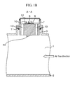
- FIG. 1A is a sensor structure view showing the embodiment of the present invention
- FIG. 1B is a sectional view taken along the line A-A in FIG. 1A .
- a sensor installation hole 3 is provided to part of a main air flow passage component (airflow tube) 2 constituting a main air flow passage 1, and a temperature/humidity detecting device 4 is attached to the sensor installation hole 3 via a seal material 11.
- a housing 7 including a connector 5 and connector terminals 6 in an integrated manner serves as a foundation, an electronic circuit board 9 for temperature and humidity detection on which a temperature/humidity sensing element 8 is mounted is placed on the foundation, and the structure is closed with a cover 12.
- the connector terminals 6 are each electrically connected to the electronic circuit board 9 for temperature and humidity detection by a bonding wire 10, and the connector 5 mediates an input/output exchange with the outside.
- a bypass channel 13 that communicates an internal space of the housing 7 with the main air flow passage 1 is provided at each of two offset points, that is, one point on the upstream side and one point on the downstream side in an air flow direction.
- the reason why the bypass channels 13 are thus provided is that part of air flowing through the main air flow passage 1 is taken into the housing 7 via one of the bypass channels 13 by utilizing a difference in pressure between the upstream and downstream sides that is caused by airflow tube friction of the air flowing through the main air flow passage 1, to thereby generate an air flow around the temperature/humidity sensing element 8.
- the temperature and humidity detection responsiveness and measurement precision can be improved.
- the difference in pressure between the bypass channels 13 provided at two points is larger, the quantity of air flowing around the temperature/humidity sensing element 8 increases, and such a larger quantity of air is more advantageous to the measurement.
- the difference in pressure can be made larger by protruding part of the structure connected to the housing 7 to the inside of the main air flow passage 1 or providing a pressure adjustment projection 40 between the two bypass channels 13.
- the bypass channels 13 are opened near an inner wall surface of the main air flow passage 1 near which the flow rate is indefinitely close to zero.
- the polluting substances floating in the air, water droplets, and the like continue to linearly advance through the main air flow passage 1 due to an inertial effect, and the polluting substances floating in the air, water droplets, and the like do not flow into the bypass channel 13 in which an air flow is generated by the difference in pressure.
- This configuration makes it possible to allow air to flow in but prevent the polluting substances from being taken in, that is, both the resistance to pollution and the measurement performance can be achieved.
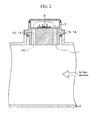
- FIG. 2 is a sectional view of the temperature/humidity detecting device 4.
- Air is caused to flow into the internal space of the housing 7, that is, around the temperature/humidity sensing element 8 via one of the bypass channels 13 by utilizing the difference in pressure between the upstream and downstream sides that is caused by the airflow tube friction of the air flowing through the main air flow passage 1.
- the bypass channel 13 that communicates the internal space of the housing 7 with the main air flow passage 1 is provided at each of two offset points, that is, one point on the upstream side and one point on the downstream side in the air flow direction.
- the bypass channel 13 provided on the upstream side in the air flow direction serves as an air intake channel 14 that takes in air for temperature and humidity measurement
- the bypass channel 13 provided on the downstream side in the air flow direction serves as an air exhaust channel 15 that exhausts the air after the temperature and humidity measurement from the inside of the housing 7.
- FIG. 3A is a front view of the temperature/humidity detecting device 4, and FIG. 3B is a sectional view around the bypass channels 13.
- the air intake channel 14 and the air exhaust channel 15 are provided in the housing 7, and an inlet 16 of the air intake channel and an outlet 17 of the air exhaust channel are each opened at a position as high as the inner wall surface of the main air flow passage 1.
- the air intake channel 14 and the air exhaust channel 15 each extend to the outside with respect to an outer wall surface of the main air flow passage component (airflow tube) 2 to be communicated with the inside of the housing 7, and this therefore defines a structural feature that the air for temperature and humidity detection flows so as to be bypassed on the outer side of the outer wall surface of the main air flow passage component (airflow tube) 2.
- This configuration makes it possible to secure a long distance between the inlet 16 of the air intake channel and the temperature/humidity sensing element 8, and hence the resistance to pollution is improved.
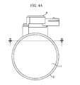
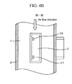
- FIG. 4A is a front view of the temperature/humidity detecting device 4, and FIG. 4B is a sectional view taken along the line B-B in FIG. 4A .
- the inlet 16 of the air intake channel and the outlet 17 of the air exhaust channel are each opened in a direction perpendicular to the air flow direction in the main air flow passage 1.
- This configuration enables an inertial effect to act to the maximum on polluting substances floating in the air flowing through the main air flow passage 1, water droplets scattered together with the air, and the like, whereby the polluting substances and the water droplets are less likely to be taken into the housing 7.
- FIG. 5A is a top view of the temperature/humidity detecting device 4 according to the present embodiment
- FIG. 5B is a sectional view taken along the line C-C in FIG. 5A .
- the sensor installation hole 3 is provided to part of the main air flow passage component (airflow tube) 2 constituting the main air flow passage 1, and the temperature/humidity detecting device 4 is attached to the sensor installation hole 3 via the seal material 11.
- the inlet 16 of the air intake channel and the outlet 17 of the air exhaust channel are each provided so as to be opened between the seal material 11 and the inner wall surface of the main air flow passage 1.
- the inlet 16 of the air intake channel and the outlet 17 of the air exhaust channel can be opened in a region where an air flow does not exist, and hence polluting substances floating in the air flowing through the main air flow passage 1, water droplets scattered together with the air, and the like are further less likely to be taken in, so that a pollution problem of the temperature/humidity sensing element 8 caused by the polluting substances, the water droplets, and the like is solved.
- part of the structure connected to the housing 7 is protruded to the inside of the main air flow passage 1, and the protruded portion is caused to function as the pressure adjustment projection 40, whereby the difference in pressure between the inlet 16 of the air intake channel and the outlet 17 of the air exhaust channel can be made larger by the action of a flow around the structure.
- This configuration can improve the measurement performance such as responsiveness as well.
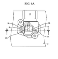
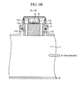
- FIG. 6A is a top view of the temperature/humidity detecting device 4 according to the present embodiment
- FIG. 6B is a sectional view taken along the line D-D in FIG. 6A .
- dividing walls 18 are provided in the housing 7, whereby the air intake channel 14 and the air exhaust channel 15 are each configured as an expanded flow channel 19 inside of the housing 7.
- the air intake channel 14 and the air exhaust channel 15 are each configured as an expanded flow channel 19 inside of the housing 7.
- the dividing wall 18 thus provided functions as a dam so as to prevent the water or polluting substances from flowing into the temperature/humidity sensing element 8 and the electronic circuit board 9 for temperature and humidity detection.
- This configuration can achieve the temperature/humidity detecting device 4 further excellent in resistance to pollution and measurement performance.
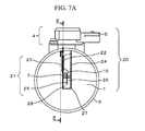
- FIG. 7A is a sensor structure view of the multifunction sensor 20
- FIG. 7B is a sectional view taken along the line E-E in FIG. 7A .
- the housing 7 including the connector 5 and the connector terminals 6 in an integrated manner serves as a foundation, the electronic circuit board 9 for temperature and humidity detection on which the temperature/humidity sensing element 8 is mounted is placed on the foundation, and the structure is closed with the cover 12.
- the connector terminals 6 are each electrically connected to the electronic circuit board 9 for temperature and humidity detection by the bonding wire 10, and the connector 5 mediates an input/output exchange with the outside.
- the air intake channel 14 and the air exhaust channel 15 that each communicate the internal space of the housing 7 with the main air flow passage 1 are respectively provided at one offset point on the upstream side and one offset point on the downstream side in the air flow direction.
- the inlet 16 of the air intake channel and the outlet 17 of the air exhaust channel respectively corresponding to an entrance of the air intake channel 14 and an exit of the air exhaust channel 15 are each provided so as to be opened between the seal material 11 and the inner wall surface of the main air flow passage 1, whereby polluting substances floating in the air flowing through the main air flow passage 1, water droplets scattered together with the air, and the like are less likely to be taken in.
- An airflow sensor 21 is integrally provided at a leading end part on the main air flow passage 1 side of these components that realize the humidity detecting function.
- the housing 7 serving as the structural foundation is extended toward the inside of the main air flow passage 1, and a region of circuit casing for the airflow sensor is defined by: a base plate 23 that holds an electronic circuit board 22 for the airflow sensor; and an airflow sensor cover 24.
- a terminal 26 of an airflow sensing element that holds an airflow sensing element 25 is provided integrally with the housing 7, and the airflow sensing element 25 is mounted inside of a secondary air flow passage 28 for the airflow sensor constituted by a secondary air flow passage component 27.
- the airflow sensing element 25 is electrically connected to the electronic circuit board 22 for the airflow sensor by the bonding wire 10, and similarly, the connector terminals 6 are each electrically connected to the electronic circuit board 22 for the airflow sensor by the bonding wire 10.
- the connector 5 mediates input/output exchanges of a temperature/humidity signal and an air flow signal with the outside.
- the airflow sensor 21 itself functions as the pressure adjustment projection 40, and hence the difference in pressure between the inlet 16 of the air intake channel and the outlet 17 of the air exhaust channel can be made larger by the action of a flow around the structure, thus enabling a structure advantageous to air supply to the temperature/humidity sensing element 8.
- This configuration can improve both the responsiveness and the measurement performance.
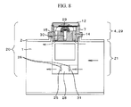
- a pressure detecting device 29 is integrally provided in a humidity detecting region defined by the housing 7 and the cover 12. Further, the housing 7 is provided with not only the air intake channel 14 and the air exhaust channel 15 that each communicate the internal space of the housing 7 with the main air flow passage 1 but also a pressure intake hole 30 located between the air intake channel 14 and the air exhaust channel 15. Still further, the airflow sensor 21 is integrally provided at a leading end part on the main air flow passage 1 side of these components that realize the humidity detecting function and the pressure detecting function.
- the terminal 26 of the airflow sensing element that holds the airflow sensing element 25 and a temperature compensation resistor 31 is provided integrally with the housing 7, and the airflow sensing element 25 and the temperature compensation resistor 31 are mounted inside of the secondary air flow passage 28 for the airflow sensor. That is, a flow channel for temperature and humidity detection constituted by the air intake channel 14 and the air exhaust channel 15, the secondary air flow passage 28 for the airflow sensor, and even the pressure intake hole 30 are independently placed so as not to structurally interfere with one another.
- the structure of the airflow sensor 21, the structure of the temperature/humidity detecting device 4, and even the structure of the pressure detecting device 29 do not interfere with one another, and it is possible to provide the multifunction sensor 20 capable of flexibly dealing with a request to add/delete a function to/from the sensor, that is, even capable of controlling whether to provide each function to the sensor.
- An intake air 51 taken from an air cleaner 50 is introduced into an engine cylinder 57 through an intake manifold 56.
- the intake manifold 56 includes: the main air flow passage component (airflow tube) 2 into which the multifunction sensor 20 is inserted; an intake air duct 53; a throttle body 54; and a fuel injector 55 supplied with fuel.
- an exhaust gas 58 generated in the engine cylinder 57 is exhausted through an exhaust manifold 59.
- An engine control unit 64 receives: an air flow signal, a humidity signal, a pressure signal, and a temperature signal outputted from the multifunction sensor 20; a throttle valve angle signal outputted from a throttle angle sensor 60; an oxygen concentration signal outputted from an oxygen meter 62 provided to the exhaust manifold 59; an engine speed signal outputted from an engine speed meter 63; and other such signals.
- the engine control unit 64 sequentially calculates these signals to obtain an optimum amount of fuel injection and an optimum output torque.
- the engine control unit 64 uses these values to control the fuel injector 55 and the throttle valve 61.
Applications Claiming Priority (1)
| Application Number | Priority Date | Filing Date | Title |
|---|---|---|---|
| JP2010227131A JP2012083119A (ja) | 2010-10-07 | 2010-10-07 | センサの構造 |
Publications (1)
| Publication Number | Publication Date |
|---|---|
| EP2439499A1 true EP2439499A1 (en) | 2012-04-11 |
Family
ID=45098844
Family Applications (1)
| Application Number | Title | Priority Date | Filing Date |
|---|---|---|---|
| EP20110184258 Withdrawn EP2439499A1 (en) | 2010-10-07 | 2011-10-07 | Sensor structure |
Country Status (4)
| Country | Link |
|---|---|
| US (1) | US20120085324A1 (ja) |
| EP (1) | EP2439499A1 (ja) |
| JP (1) | JP2012083119A (ja) |
| CN (1) | CN102538867B (ja) |
Cited By (5)
| Publication number | Priority date | Publication date | Assignee | Title |
|---|---|---|---|---|
| WO2014060161A1 (de) * | 2012-10-15 | 2014-04-24 | Robert Bosch Gmbh | Sensoranordnung zur bestimmung des feuchtegehalts eines in einer hauptströmungsrichtung strömenden fluiden mediums |
| EP2976629A1 (de) * | 2013-03-22 | 2016-01-27 | Robert Bosch GmbH | Sensorvorrichtung zur erfassung einer feuchte eines strömenden fluiden mediums |
| CN105783987A (zh) * | 2014-12-26 | 2016-07-20 | 摩瑞尔电器(昆山)有限公司 | 一种空气检测终端 |
| DE102020125285A1 (de) | 2020-09-28 | 2022-03-31 | HELLA GmbH & Co. KGaA | Montageeinheit zur Montage einer Sensorvorrichtung an einer eine Gasströmung begrenzenden Wandung |
| AT524543A4 (de) * | 2021-03-25 | 2022-07-15 | Avl List Gmbh | Messvorrichtung zur Bestimmung eines Stickstoff- und/oder Wasserstoffdurchflusses |
Families Citing this family (30)
| Publication number | Priority date | Publication date | Assignee | Title |
|---|---|---|---|---|
| KR101748875B1 (ko) * | 2010-08-20 | 2017-06-19 | 두산인프라코어 주식회사 | 전자식 터보차저 엔진의 부스트 압력센서 장착용 어댑터 구조 |
| JP5779471B2 (ja) | 2011-10-06 | 2015-09-16 | 日立オートモティブシステムズ株式会社 | 湿度検出装置 |
| US10240867B2 (en) | 2012-02-01 | 2019-03-26 | Revive Electronics, LLC | Methods and apparatuses for drying electronic devices |
| ES2709693T3 (es) | 2012-02-01 | 2019-04-17 | Revive Electronics Llc | Métodos y aparatos para el secado de dispositivos electrónicos |
| US9644891B2 (en) | 2012-02-01 | 2017-05-09 | Revive Electronics, LLC | Methods and apparatuses for drying electronic devices |
| WO2016105505A1 (en) * | 2014-12-23 | 2016-06-30 | Revive Electronics, LLC | Apparatuses and methods for controlling power to electronic devices |
| US10876792B2 (en) | 2012-02-01 | 2020-12-29 | Revive Electronics, LLC | Methods and apparatuses for drying electronic devices |
| US9513053B2 (en) | 2013-03-14 | 2016-12-06 | Revive Electronics, LLC | Methods and apparatuses for drying electronic devices |
| US11713924B2 (en) | 2012-02-01 | 2023-08-01 | Revive Electronics, LLC | Methods and apparatuses for drying electronic devices |
| US10690413B2 (en) | 2012-02-01 | 2020-06-23 | Revive Electronics, LLC | Methods and apparatuses for drying electronic devices |
| US9970708B2 (en) | 2012-02-01 | 2018-05-15 | Revive Electronics, LLC | Methods and apparatuses for drying electronic devices |
| JP5675717B2 (ja) * | 2012-06-29 | 2015-02-25 | 日立オートモティブシステムズ株式会社 | 空気物理量検出装置 |
| US9488565B2 (en) | 2012-11-14 | 2016-11-08 | Revive Electronics, LLC | Method and apparatus for detecting moisture in portable electronic devices |
| DK201300257A1 (en) * | 2013-05-01 | 2014-11-02 | Paj Sensor As | Free water in scavenge air sensor system and method for monitoring free water in scavenge air |
| JP6099094B2 (ja) * | 2013-06-21 | 2017-03-22 | 日立オートモティブシステムズ株式会社 | ガスセンサ装置およびガスセンサ装置の取付け構造 |
| JP6035582B2 (ja) * | 2013-10-30 | 2016-11-30 | 株式会社デンソー | 空気流量測定装置及びその製造方法 |
| JP6194852B2 (ja) * | 2014-06-06 | 2017-09-13 | 株式会社デンソー | 湿度検出機能付き空気流量測定装置 |
| JP6237495B2 (ja) | 2014-06-27 | 2017-11-29 | 株式会社デンソー | 空気流量測定装置 |
| WO2016017301A1 (ja) * | 2014-07-30 | 2016-02-04 | 日立オートモティブシステムズ株式会社 | 物理量検出装置 |
| US10591331B2 (en) | 2015-09-30 | 2020-03-17 | Hitachi Automotive Systems, Ltd. | Intake temperature detection device and maximum heat generating amount components mounted on a single circuit board |
| DE102015016160A1 (de) * | 2015-12-12 | 2017-06-14 | Man Diesel & Turbo Se | System zum Zuführen von Luft zu Zylindern einer Brennkraftmaschine |
| US20190219529A1 (en) * | 2016-05-23 | 2019-07-18 | Hitachi Automotive Systems, Ltd. | Humidity Measuring Apparatus |
| JP6798336B2 (ja) * | 2017-02-08 | 2020-12-09 | 株式会社デンソー | 絶対湿度センサ |
| JP2018179883A (ja) * | 2017-04-19 | 2018-11-15 | 株式会社デンソー | 物理量計測装置 |
| JP6851466B2 (ja) * | 2017-04-21 | 2021-03-31 | 日立Astemo株式会社 | 湿度測定装置 |
| US11268920B2 (en) * | 2017-09-29 | 2022-03-08 | Hitachi Automotive Systems, Ltd. | Physical quantity detection device |
| JP2021014987A (ja) * | 2017-10-10 | 2021-02-12 | 日立オートモティブシステムズ株式会社 | 湿度測定装置 |
| CN108036829A (zh) * | 2017-10-17 | 2018-05-15 | 浙江博美泰克电子有限公司 | 四合一高精度汽车空气流量计 |
| CN112136024B (zh) * | 2018-05-17 | 2023-08-18 | 日立安斯泰莫株式会社 | 物理量检测装置 |
| CN112268939B (zh) * | 2020-10-27 | 2022-07-12 | 东南大学 | 一种基于机械超材料结构的湿度传感器 |
Citations (3)
| Publication number | Priority date | Publication date | Assignee | Title |
|---|---|---|---|---|
| US4131011A (en) * | 1977-02-28 | 1978-12-26 | Abbott Laboratories | Method and device for determining the end point for drying |
| US20080163683A1 (en) * | 2007-01-04 | 2008-07-10 | Honeywell International Inc. | Packaging methods and systems for measuring multiple measurands including bi-directional flow |
| EP2154494A1 (en) * | 2008-08-11 | 2010-02-17 | Hitachi Automotive Systems Ltd. | Mass air flow measurement device |
Family Cites Families (4)
| Publication number | Priority date | Publication date | Assignee | Title |
|---|---|---|---|---|
| JP3264605B2 (ja) * | 1995-05-26 | 2002-03-11 | リンナイ株式会社 | 風速センサ |
| US6655207B1 (en) * | 2000-02-16 | 2003-12-02 | Honeywell International Inc. | Flow rate module and integrated flow restrictor |
| JP4416012B2 (ja) * | 2007-06-06 | 2010-02-17 | 株式会社日立製作所 | 吸入空気流量測定装置 |
| JP4929333B2 (ja) * | 2009-09-30 | 2012-05-09 | 日立オートモティブシステムズ株式会社 | センサの構造 |
-
2010
- 2010-10-07 JP JP2010227131A patent/JP2012083119A/ja active Pending
-
2011
- 2011-09-30 CN CN201110305311.5A patent/CN102538867B/zh not_active Expired - Fee Related
- 2011-10-06 US US13/267,419 patent/US20120085324A1/en not_active Abandoned
- 2011-10-07 EP EP20110184258 patent/EP2439499A1/en not_active Withdrawn
Patent Citations (4)
| Publication number | Priority date | Publication date | Assignee | Title |
|---|---|---|---|---|
| US4131011A (en) * | 1977-02-28 | 1978-12-26 | Abbott Laboratories | Method and device for determining the end point for drying |
| US20080163683A1 (en) * | 2007-01-04 | 2008-07-10 | Honeywell International Inc. | Packaging methods and systems for measuring multiple measurands including bi-directional flow |
| EP2154494A1 (en) * | 2008-08-11 | 2010-02-17 | Hitachi Automotive Systems Ltd. | Mass air flow measurement device |
| JP2010043883A (ja) | 2008-08-11 | 2010-02-25 | Hitachi Ltd | 空気流量測定装置 |
Cited By (8)
| Publication number | Priority date | Publication date | Assignee | Title |
|---|---|---|---|---|
| WO2014060161A1 (de) * | 2012-10-15 | 2014-04-24 | Robert Bosch Gmbh | Sensoranordnung zur bestimmung des feuchtegehalts eines in einer hauptströmungsrichtung strömenden fluiden mediums |
| US9964506B2 (en) | 2012-10-15 | 2018-05-08 | Robert Bosch Gmbh | Sensor system for determining the moisture content of a fluid medium flowing in a main flow direction |
| EP2976629A1 (de) * | 2013-03-22 | 2016-01-27 | Robert Bosch GmbH | Sensorvorrichtung zur erfassung einer feuchte eines strömenden fluiden mediums |
| EP2976629B1 (de) * | 2013-03-22 | 2022-03-09 | Robert Bosch GmbH | Sensorvorrichtung zur erfassung einer feuchte eines strömenden fluiden mediums |
| CN105783987A (zh) * | 2014-12-26 | 2016-07-20 | 摩瑞尔电器(昆山)有限公司 | 一种空气检测终端 |
| DE102020125285A1 (de) | 2020-09-28 | 2022-03-31 | HELLA GmbH & Co. KGaA | Montageeinheit zur Montage einer Sensorvorrichtung an einer eine Gasströmung begrenzenden Wandung |
| AT524543A4 (de) * | 2021-03-25 | 2022-07-15 | Avl List Gmbh | Messvorrichtung zur Bestimmung eines Stickstoff- und/oder Wasserstoffdurchflusses |
| AT524543B1 (de) * | 2021-03-25 | 2022-07-15 | Avl List Gmbh | Messvorrichtung zur Bestimmung eines Stickstoff- und/oder Wasserstoffdurchflusses |
Also Published As
| Publication number | Publication date |
|---|---|
| US20120085324A1 (en) | 2012-04-12 |
| CN102538867A (zh) | 2012-07-04 |
| CN102538867B (zh) | 2015-06-10 |
| JP2012083119A (ja) | 2012-04-26 |
Similar Documents
| Publication | Publication Date | Title |
|---|---|---|
| EP2439499A1 (en) | Sensor structure | |
| EP2487355B1 (en) | Sensor structure | |
| CN101650204B (zh) | 空气流量测定装置 | |
| CN101319952B (zh) | 吸入空气流量测量装置 | |
| CN105324644B (zh) | 物理量测量装置 | |
| US8215160B2 (en) | Sensor structure | |
| CN102636227B (zh) | 传感器的结构 | |
| JP5779471B2 (ja) | 湿度検出装置 | |
| US11112286B2 (en) | Thermal flowmeter | |
| WO2020202722A1 (ja) | 物理量検出装置 | |
| JPS62162737A (ja) | 内燃機関のためのエアフロ−メ−タを備えた装置 | |
| JPWO2020202791A1 (ja) | 物理量検出装置 | |
| JP3561219B2 (ja) | 発熱抵抗式流量測定装置 | |
| JP5462114B2 (ja) | 発熱抵抗体式空気流量測定装置 | |
| JPH0943020A (ja) | 発熱抵抗式流量測定装置 |
Legal Events
| Date | Code | Title | Description |
|---|---|---|---|
| AK | Designated contracting states |
Kind code of ref document: A1 Designated state(s): AL AT BE BG CH CY CZ DE DK EE ES FI FR GB GR HR HU IE IS IT LI LT LU LV MC MK MT NL NO PL PT RO RS SE SI SK SM TR |
|
| AX | Request for extension of the european patent |
Extension state: BA ME |
|
| PUAI | Public reference made under article 153(3) epc to a published international application that has entered the european phase |
Free format text: ORIGINAL CODE: 0009012 |
|
| 17P | Request for examination filed |
Effective date: 20120309 |
|
| 17Q | First examination report despatched |
Effective date: 20150309 |
|
| STAA | Information on the status of an ep patent application or granted ep patent |
Free format text: STATUS: THE APPLICATION IS DEEMED TO BE WITHDRAWN |
|
| 18D | Application deemed to be withdrawn |
Effective date: 20150721 |