EP2439095A1 - Automatische Verschlussvorrichtung für Kraftstofftanks - Google Patents
Automatische Verschlussvorrichtung für Kraftstofftanks Download PDFInfo
- Publication number
- EP2439095A1 EP2439095A1 EP11184187A EP11184187A EP2439095A1 EP 2439095 A1 EP2439095 A1 EP 2439095A1 EP 11184187 A EP11184187 A EP 11184187A EP 11184187 A EP11184187 A EP 11184187A EP 2439095 A1 EP2439095 A1 EP 2439095A1
- Authority
- EP
- European Patent Office
- Prior art keywords
- closure member
- closure
- bayonet ring
- closure device
- filler neck
- Prior art date
- Legal status (The legal status is an assumption and is not a legal conclusion. Google has not performed a legal analysis and makes no representation as to the accuracy of the status listed.)
- Granted
Links
- 239000002828 fuel tank Substances 0.000 title claims description 3
- 239000000945 filler Substances 0.000 claims abstract description 28
- 230000002093 peripheral effect Effects 0.000 claims description 7
- 239000011324 bead Substances 0.000 claims description 4
- 230000000630 rising effect Effects 0.000 claims 1
- 210000000078 claw Anatomy 0.000 description 9
- 239000000446 fuel Substances 0.000 description 7
- 238000011161 development Methods 0.000 description 2
- 230000018109 developmental process Effects 0.000 description 2
- 238000006073 displacement reaction Methods 0.000 description 1
- 239000002360 explosive Substances 0.000 description 1
- 238000009434 installation Methods 0.000 description 1
- 239000000203 mixture Substances 0.000 description 1
- 238000007789 sealing Methods 0.000 description 1
Images


Classifications
-
- B—PERFORMING OPERATIONS; TRANSPORTING
- B60—VEHICLES IN GENERAL
- B60K—ARRANGEMENT OR MOUNTING OF PROPULSION UNITS OR OF TRANSMISSIONS IN VEHICLES; ARRANGEMENT OR MOUNTING OF PLURAL DIVERSE PRIME-MOVERS IN VEHICLES; AUXILIARY DRIVES FOR VEHICLES; INSTRUMENTATION OR DASHBOARDS FOR VEHICLES; ARRANGEMENTS IN CONNECTION WITH COOLING, AIR INTAKE, GAS EXHAUST OR FUEL SUPPLY OF PROPULSION UNITS IN VEHICLES
- B60K15/00—Arrangement in connection with fuel supply of combustion engines or other fuel consuming energy converters, e.g. fuel cells; Mounting or construction of fuel tanks
- B60K15/03—Fuel tanks
- B60K15/04—Tank inlets
- B60K15/0406—Filler caps for fuel tanks
- B60K15/0409—Provided with a lock
- B60K2015/0416—Provided with a lock electrically actuated
-
- B—PERFORMING OPERATIONS; TRANSPORTING
- B60—VEHICLES IN GENERAL
- B60K—ARRANGEMENT OR MOUNTING OF PROPULSION UNITS OR OF TRANSMISSIONS IN VEHICLES; ARRANGEMENT OR MOUNTING OF PLURAL DIVERSE PRIME-MOVERS IN VEHICLES; AUXILIARY DRIVES FOR VEHICLES; INSTRUMENTATION OR DASHBOARDS FOR VEHICLES; ARRANGEMENTS IN CONNECTION WITH COOLING, AIR INTAKE, GAS EXHAUST OR FUEL SUPPLY OF PROPULSION UNITS IN VEHICLES
- B60K15/00—Arrangement in connection with fuel supply of combustion engines or other fuel consuming energy converters, e.g. fuel cells; Mounting or construction of fuel tanks
- B60K15/03—Fuel tanks
- B60K15/04—Tank inlets
- B60K15/0406—Filler caps for fuel tanks
- B60K2015/0419—Self-sealing closure caps, e.g. that don't have to be removed manually
- B60K2015/0425—Self-sealing closure caps, e.g. that don't have to be removed manually actuated by a motor
-
- B—PERFORMING OPERATIONS; TRANSPORTING
- B60—VEHICLES IN GENERAL
- B60K—ARRANGEMENT OR MOUNTING OF PROPULSION UNITS OR OF TRANSMISSIONS IN VEHICLES; ARRANGEMENT OR MOUNTING OF PLURAL DIVERSE PRIME-MOVERS IN VEHICLES; AUXILIARY DRIVES FOR VEHICLES; INSTRUMENTATION OR DASHBOARDS FOR VEHICLES; ARRANGEMENTS IN CONNECTION WITH COOLING, AIR INTAKE, GAS EXHAUST OR FUEL SUPPLY OF PROPULSION UNITS IN VEHICLES
- B60K15/00—Arrangement in connection with fuel supply of combustion engines or other fuel consuming energy converters, e.g. fuel cells; Mounting or construction of fuel tanks
- B60K15/03—Fuel tanks
- B60K15/04—Tank inlets
- B60K15/05—Inlet covers
- B60K2015/0515—Arrangements for closing or opening of inlet cover
- B60K2015/0538—Arrangements for closing or opening of inlet cover with open or close mechanism automatically actuated
Definitions
- the invention relates to an automatic closure device for fuel tanks, with a closure member designed for sealing a filler neck, which is pivotable between an open position and a closed position and lockable in its closed position by means of a drive and a bayonet ring arranged rotatably drivable on the filler neck.
- the object of the invention is to provide a closure device which provides greater security in a collision.
- Another advantage is that the installation of the closure system essential is facilitated, since at least the components of the closure device, which serve to lock the closure member in its closed position, already finished on the filler neck can be mounted before the tank is installed in the vehicle.
- the drive has a pinion that meshes with a ring gear formed on the bayonet ring.
- a ring gear formed on the bayonet ring.
- the bayonet ring and the drive are held in a sleeve which encloses the mouth of the tank neck.
- the pivot bearing for the closure member may be disposed on this sleeve.
- a cam is formed on the bayonet ring or a part rotatable with the bayonet ring, which controls the pivoting movement of the closure member.
- the rotation of the bayonet ring caused by the drive can thus be used at the same time to pivot the closure member from the open position to the closed position or vice versa.
- the closure member may be biased by a spring in the open position.
- the cam is then formed and arranged to act on a lug of the closure member and pivot this closure member against the spring force to the closed position before final locking occurs with the aid of the bayonet ring.
- the closure member is coupled by a linkage with a fuel filler flap, which closes a tank opening in the body, so that when closing the fuel filler flap and the closure member is automatically pivoted into the closed position.
- the linkage can then have a predetermined breaking point or be designed so weak that in a collision the forces transmitted to the closure member are limited.
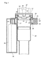
- Fig. 1 are a filler neck 10 of a motor vehicle and a closure member 12 which closes the opening of the tank neck 10, shown in an axial section.
- the closure member 12 has an upper lid part 14, a lower lid part 16 and a peripheral seal 18, which seals on the ungebörtelten upper edge of the filler neck 10. Between the upper part and the lower part of the lid, a not shown over / vacuum valve can be accommodated.
- the lower cover part 16 has at its peripheral edge three downwardly projecting, bent-out bayonet claws 20, of which in Fig. 1 only one to recognize is. These bayonet claws 20 engage behind a bayonet ring 22 which surrounds the upper end of the filler neck 10.
- the bayonet ring 22 is rotatably and axially fixed in a surrounding the tank neck cuff 24.
- the cuff 24 has a lower part composed of two half-rings 26, 27 and an annular upper part 28 which is securely fastened to the lower part.
- the two half rings 26, 27 of the lower part form at the inner peripheral edge a circumferential bead 30, which engages positively in a bead 32 of the filler neck 10.
- the bayonet ring 22 is received in a groove of the base, which is closed at the top by the upper part 28, so that the bayonet ring can not escape upwards from the sleeve 24.
- the annular upper part 28 and the bayonet ring 22 have at the inner peripheral edge on each three recesses through which the bayonet claws 20 of the closure member can pass.
- Fig. 1 shows the bayonet ring 22 in a state in which it is rotated so far around the axis of the filler neck 10 that the bayonet claws 20 are offset from the mentioned recesses and are overlapped by the upper edge of the bayonet ring 22. In this way, the closure member 12 is positively locked in a position in which it closes the opening of the filler neck 10 tightly.
- the half-ring 27 of the sleeve 24 forms a housing 34 which extends laterally along the filler neck 10 and receives a motor 36 whose output shaft carries a pinion 38.
- the pinion 38 meshes with a ring gear 40 formed on the outer circumference of the bayonet ring 22. In this way, a drive is formed with which the bayonet ring 22 can be rotated between the locking position and the unlocking position.
- the closure member 12 is pivotally supported on the sleeve 24.
- the sleeve at one point of its circumference on a pivot bearing 42, in which a hinge axis 44 is mounted for the closure member 12.
- the hinge axis 44 passes through an upstanding from the edge of the closure member 12 approach 46, above the hinge axis is angled outwards and forms a cam follower 48.
- the closure member 12 is connected to a spring, not shown, for example by means of a hinge spring surrounding the hinge axis 44, in the in Fig. 2 biased open position shown.
- the bayonet ring 22 has at its outer peripheral edge on a radially projecting arm, from which a cam 50 rises, which abuts against the cam follower 48 and thus limits the opening-pivotal movement of the closure member 12.
- the cam 50 has a helically extending upper edge so that when the bayonet ring 22 is rotated by means of the motor 36, it pushes the cam follower 48 upwardly to pivot the closure member 12 to the closed position, as in FIG Fig. 3 is shown.
- the bayonet claws 20 enter through the aforementioned recesses of the upper part 28 into the interior of the bayonet ring 22.
- FIG. 2 one of the mentioned recesses 52 in the bayonet ring 22 is shown.
- the bayonet ring 22 has been rotated so far that these recesses 52 are aligned with the bayonet claws 20 so that the bayonet claws can pass through the recesses 52 further into the bayonet ring.
- Upon further rotation of the bayonet ring 22 then enters the position according to Fig. 1 in which he locks the closure member 12 to the bayonet claws 20.
- At the bayonet ring 22 and / or at the bayonet claws 20 may be formed bevels, which cause the closure member 12 is tightened on reaching the locking position against the edge of the fuel nozzle 10 and thereby the seal 18 is compressed, so that a reliable seal is achieved ,
- the cam moves in a housing 54 that extends along the peripheral edge of the collar 24.
- the motor 36 may be associated with a displacement or position sensor which outputs an acknowledgment signal when the bayonet ring has reached the locking position.
- the filler neck 10 with the closure device described here will usually lie behind a tank opening formed in the vehicle body, which is closed by a fuel filler flap.
- the closure member 12 may be connected by a linkage with this tank flap, so that when the closure member 12 pivots in the open position, at the same time the fuel filler flap is opened.
- the aforementioned spring which biases the closure member 12 in the open position, also engage the fuel filler flap, which pulls the closure member in the open position via the linkage.
Landscapes
- Engineering & Computer Science (AREA)
- Life Sciences & Earth Sciences (AREA)
- Sustainable Development (AREA)
- Sustainable Energy (AREA)
- Chemical & Material Sciences (AREA)
- Combustion & Propulsion (AREA)
- Transportation (AREA)
- Mechanical Engineering (AREA)
- Cooling, Air Intake And Gas Exhaust, And Fuel Tank Arrangements In Propulsion Units (AREA)
Abstract
Description
- Die Erfindung betrifft eine automatische Verschlussvorrichtung für Kraftstofftanks, mit einem zum dichten Schließen eines Tankstutzens ausgebildeten Verschlussglied, das zwischen einer Öffnungsstellung und einer Schließstellung schwenkbar und mit Hilfe eines Antriebs und eines drehantreibbar am Tankstutzen angeordneten Bajonettrings in seiner Schließstellung verriegelbar ist.
- Aus
DE 299 13 204 U1 ist eine Verschlussvorrichtung dieser Art bekannt, bei der der Antrieb an der Fahrzeugkarosserie gehalten und über ein Gestänge mit dem Bajonettring verbunden ist. Wenn das Fahrzeug in eine Kollision verwickelt ist, in der die Karosserie im Bereich des Tankstutzens verformt wird, besteht die Gefahr, dass die Aufprallkräfte der Kollision über das Gestänge auf das Verschlussglied übertragen werden, so dass dieses nicht mehr dicht schließt und ein explosives Kraftstoff/Luft-Gemisch entweichen kann. - Aufgabe der Erfindung ist es, eine Verschlussvorrichtung zu schaffen, die bei einer Kollision eine höhere Sicherheit bietet.
- Diese Aufgabe wird dadurch gelöst, dass der Antrieb am Tankstutzen gehalten ist.
- Wenn sich bei einer Kollision die Karosserie im Bereich des Tankstutzens verformt, kann ein Teil der Aufprallenergie von der Karosserie aufgezehrt werden, ohne dass die Kollisionskräfte auf den Antrieb und das Verschlussglied übertragen werden. Selbst wenn der Aufprall so heftig ist, dass auch der Tankstutzen verformt wird, nimmt der Antrieb an der Bewegung des Tankstutzens teil, so dass auch in diesem Fall eine höhere Wahrscheinlichkeit besteht, dass die Dichtheit des Verschlusssystems gewährleistet bleibt.
- Ein weiterer Vorteil besteht darin, dass die Montage des Verschlusssystems wesentlich erleichtert wird, da zumindest die Komponenten der Verschlussvorrichtung, die zur Verriegelung des Verschlussgliedes in seiner Schließstellung dienen, bereits fertig am Tankstutzen montiert werden können, bevor der Tank in das Fahrzeug eingebaut wird.
- Vorteilhafte Ausgestaltungen und Weiterbildungen der Erfindung sind in den Unteransprüchen angegeben.
- In einer bevorzugten Ausführungsform weist der Antrieb ein Ritzel auf, das mit einem am Bajonettring gebildeten Zahnkranz kämmt. Das erlaubt eine besonders kompakte Anordnung, bei der die Achse des Ritzels und eines zum Antrieb des Ritzels dienenden Motors parallel zum Tankstutzen verlaufen. Bevorzugt sind der Bajonettring und der Antrieb in einer Manschette gehalten, die die Mündung des Tankstutzens umschließt. Auch das Schwenklager für das Verschlussglied kann an dieser Manschette angeordnet sein.
- Alternativ ist jedoch ein Antrieb mittels Schnecke oder Zahnstange denkbar.
- Gemäß einer vorteilhaften Weiterbildung ist an dem Bajonettring oder einem mit dem Bajonettring mitdrehbaren Teil ein Nocken gebildet, der die Schwenkbewegung des Verschlussgliedes steuert. Die durch den Antrieb bewirkte Drehung des Bajonettrings kann somit zugleich dazu genutzt werden, das Verschlussglied aus der Öffnungsstellung in die Schließstellung zu verschwenken oder umgekehrt. Beispielsweise kann das Verschlussglied durch eine Feder in die Öffnungsstellung vorgespannt sein. Der Nocken ist dann so ausgebildet und angeordnet, dass er auf einen Ansatz des Verschlussgliedes wirkt und dieses Verschlussglied entgegen der Federkraft in die Schließstellung schwenkt, bevor die endgültige Verriegelung mit Hilfe des Bajonettrings erfolgt.
- Bei der aus
DE 299 13 204 U1 bekannten Vorrichtung ist das Verschlussglied durch ein Gestänge mit einer Tankklappe gekoppelt, die eine Tanköffnung in der Karosserie verschließt, so dass beim Schließen der Tankklappe automatisch auch das Verschlussglied in die Schließstellung geschwenkt wird. Dasselbe ist auch bei der erfindungsgemäßen Vorrichtung möglich. Das Gestänge kann dann eine Sollbruchstelle aufweisen oder so schwach ausgebildet sein, dass bei einer Kollision die auf das Verschlussglied übertragenen Kräfte begrenzt werden. Wenn die Schwenkbewegung des Verschlussgliedes durch einen Nocken am Bajonettring gesteuert wird, ermöglicht es das Gestänge, mit Hilfe des Antriebs und des Nockens auch die Schließbewegung der Tankklappe zu steuern. - Im folgenden wird ein Ausführungsbeispiel der Erfindung anhand der Zeichnung näher erläutert.
- Es zeigen:
- Fig. 1
- einen axialen Schnitt durch einen Tankstutzen mit einer erfindungsgemäβen Verschlussvorrichtung;
- Fig. 2
- einen Schnitt in einer gegenüber
Fig. 1 um 90° gedrehten Schnittebene bei geöffnetem Verschlussglied; und - Fig. 3
- eine Schnittdarstellung entsprechend
Fig. 2 für die geschlossene Position des Verschlussgliedes. - In
Fig. 1 sind ein Tankstutzen 10 eines Kraftfahrzeugs und ein Verschlussglied 12, das die Öffnung des Tankstutzens 10 verschließt, in einem axialen Schnitt dargestellt. Das Verschlussglied 12 weist ein Deckeloberteil 14, ein Deckelunterteil 16 und eine umlaufende Dichtung 18 auf, die auf dem ungebörtelten oberen Rand des Tankstutzens 10 abdichtet. Zwischen Oberteil und Unterteil des Deckels kann ein nicht gezeigtes Über/Unterdruckventil untergebracht sein. - Das Deckelunterteil 16 weist an seinem Umfangsrand drei nach unten vorspringende, nach außen gekröpfte Bajonettklauen 20 auf, von denen in
Fig. 1 nur eine zu erkennen ist. Diese Bajonettklauen 20 hintergreifen einen Bajonettring 22, der das obere Ende des Tankstutzens 10 umgibt. Der Bajonettring 22 ist drehbar und axialfest in einer den Tankstutzen umgebenden Manschette 24 gehalten. Die Manschette 24 weist ein aus zwei Halbringen 26, 27 zusammengesetztes Unterteil und ein ringförmiges Oberteil 28 auf, das sicher auf dem Unterteil befestigt ist. Die beiden Halbringe 26, 27 des Unterteils bilden am inneren Umfangsrand einen umlaufenden Wulst 30, der formschlüssig in eine Sicke 32 des Tankstutzens 10 eingreift. - Der Bajonettring 22 ist in einer Nut des Unterteils aufgenommen, die nach oben durch das Oberteil 28 abgeschlossen wird, so dass der Bajonettring nicht nach oben aus der Manschette 24 austreten kann. Das ringförmige Oberteil 28 und der Bajonettring 22 weisen am inneren Umfangsrand je drei Ausnehmungen auf, durch die die Bajonettklauen 20 des Verschlussgliedes hindurchtreten können.
Fig. 1 zeigt den Bajonettring 22 in einem Zustand, in dem er so weit um die Achse des Tankstutzens 10 verdreht ist, dass die Bajonettklauen 20 versetzt zu den erwähnten Ausnehmungen liegen und vom oberen Rand des Bajonettrings 22 übergriffen werden. Auf diese Weise wird das Verschlussglied 12 formschlüssig in einer Position verriegelt, in der es die Öffnung des Tankstutzens 10 dicht verschließt. - Der Halbring 27 der Manschette 24 bildet ein Gehäuse 34, das sich seitlich längs des Tankstutzens 10 erstreckt und einen Motor 36 aufnimmt, dessen Ausgangswelle ein Ritzel 38 trägt. Das Ritzel 38 kämmt mit einem Zahnkranz 40, der am äußeren Umfang des Bajonettrings 22 gebildet ist. Auf diese Weise wird ein Antrieb gebildet, mit dem sich der Bajonettring 22 zwischen der Verriegelungsposition und der Entriegelungsposition verdrehen lässt.
- Wie
Fig. 2 zeigt, ist das Verschlussglied 12 schwenkbar an der Manschette 24 gehalten. Dazu weist die Manschette an einer Stelle ihres Umfangs ein Schwenklager 42 auf, in dem eine Gelenkachse 44 für das Verschlussglied 12 gelagert ist. Die Gelenkachse 44 durchsetzt einen vom Rand des Verschlussgliedes 12 aufragenden Ansatz 46, der oberhalb der Gelenkachse nach außen abgewinkelt ist und einen Nockenfolger 48 bildet. - Das Verschlussglied 12 ist mit einer nicht gezeigten Feder, beispielsweise mit Hilfe einer die Gelenkachse 44 umgebenden Schenkelfeder, in die in
Fig. 2 gezeigte Öffnungsstellung vorgespannt. Der Bajonettring 22 weist an seinem äußeren Umfangsrand einen radial vorspringenden Arm auf, von dem ein Nocken 50 aufragt, der an dem Nockenfolger 48 anliegt und so die Öffnungs-Schwenkbewegung des Verschlussgliedes 12 begrenzt. - Der Nocken 50 weist einen schraubenförmig verlaufenden oberen Rand auf, so dass er, wenn der Bajonettring 22 mit Hilfe des Motors 36 gedreht wird, den Nockenfolger 48 nach oben drückt und so das Verschlussglied 12 in die Schließstellung schwenkt, wie in
Fig. 3 gezeigt ist. - Gegen Ende dieser Schwenkbewegung treten die Bajonettklauen 20 durch die erwähnten Ausnehmungen des Oberteils 28 hindurch in das Innere des Bajonettrings 22 ein. In der Schnittdarstellung in
Fig. 2 ist eine der erwähnten Ausnehmungen 52 im Bajonettring 22 gezeigt. Wenn das Verschlussglied 12 die Schließstellung erreicht, ist der Bajonettring 22 so weit gedreht worden, dass diese Ausnehmungen 52 mit den Bajonettklauen 20 fluchten, so dass die Bajonettklauen durch die Ausnehmungen 52 hindurch weiter in den Bajonettring eintreten können. Bei der weiteren Drehung gelangt der Bajonettring 22 dann in die Position gemäßFig. 1 , in der er das Verschlussglied 12 an den Bajonettklauen 20 verriegelt. Am Bajonettring 22 und/oder an den Bajonettklauen 20 können Schrägen ausgebildet sein, die bewirken, dass das Verschlussglied 12 beim Erreichen der Verriegelungsstellung fester gegen den Rand des Tankstutzens 10 gezogen wird und dadurch die Dichtung 18 komprimiert wird, so dass eine zuverlässige Abdichtung erreicht wird. - Bei der Drehung des Bajonettrings 22 bewegt sich der Nocken in einem Gehäuse 54, das sich längs des Umfangsrandes der Manschette 24 erstreckt.
- Dem Motor 36 kann ein Weg- oder Positionsgeber zugeordnet sein, der ein Bestätigungssignal ausgibt, wenn der Bajonettring die Verriegelungsposition erreicht hat.
- Wenn das Verschlussglied 12 geöffnet werden soll, so wird der Motor 36 in entgegengesetzter Richtung angetrieben, und der oben geschilderte Bewegungsablauf vollzieht sich in umgekehrter Richtung, wobei das Verschlussglied 12 durch die erwähnte Feder in die Öffnungsstellung geschwenkt wird.
- In der Praxis wird der Tankstutzen 10 mit der hier beschriebenen Verschlussvorrichtung zumeist hinter einer in der Fahrzeugkarosserie gebildeten Tanköffnung liegen, die durch eine Tankklappe verschlossen ist. Wahlweise kann das Verschlussglied 12 durch ein Gestänge mit dieser Tankklappe verbunden sein, so dass, wenn das Verschlussglied 12 in die Öffnungsstellung schwenkt, zugleich auch die Tankklappe geöffnet wird. In diesem Fall kann die erwähnte Feder, die das Verschlussglied 12 in die Öffnungsstellung vorspannt, auch an der Tankklappe angreifen, die über das Gestänge das Verschlussglied in Öffnungsstellung zieht.
Claims (8)
- Automatische Verschlussvorrichtung für Kraftstofftanks, mit einem zum dichten Schließen eines Tankstutzens (10) ausgebildeten Verschlussglied (12), das zwischen einer Öffnungsstellung und einer Schließstellung schwenkbar und mit Hilfe eines Antriebs (36, 38) und eines drehantreibbar am Tankstutzen (10) angeordneten Bajonettrings (22) in seiner Schließstellung verriegelbar ist, dadurch gekennzeichnet, dass der Antrieb (36, 38) am Tankstutzen (10) gehalten ist.
- Verschlussvorrichtung nach Anspruch 1, bei der der Antrieb ein Ritzel (38) aufweist, das mit einem Zahnkranz (40) am Umfang des Bajonettrings (22) kämmt.
- Verschlussvorrichtung nach Anspruch 1 oder 2, bei der der Bajonettring drehbar und axialfest in einer Manschette (24) aufgenommen ist, die den Tankstutzen (10) umgibt und axialfest an diesem gehalten ist.
- Verschlussvorrichtung nach Anspruch 3, bei der die Manschette (24) am inneren Umfangsrand einen Wulst (30) aufweist, der in eine Sicke (32) des Tankstutzens (10) eingereift.
- Verschlussvorrichtung nach einem der vorstehenden Ansprüche, bei der am Bajonettring (22) ein Nocken (50) gebildet ist, der mit einem im Bereich eines Schwenklagers (42) vom Verschlussglied (12) vorspringenden Nockenfolger (48) zusammenwirkt und die Schwenkbewegung des Verschlussgliedes (12) steuert.
- Verschlussvorrichtung nach Anspruch 5, bei der das Verschlussglied (12) elastisch in seine Öffnungsstellung vorgespannt ist und der Nocken (50) die Schließbewegung des Verschlussgliedes steuert.
- Verschlussvorrichtung nach den Ansprüchen 3 und 5, bei der das Schwenklager (42) für das Verschlussglied (12) an der Manschette (24) angeordnet ist.
- Verschlussvorrichtung nach den Ansprüchen 6 und 7, bei der das Verschlussglied (12) über einen von dessen Rand aufragenden Ansatz (46) mit dem Schwenklager (42) verbunden ist, der Nockenfolger (48) radial vom oberen Ende des Ansatzes (46) vorspringt, und der Nocken (50) einen schraubenförmig verlaufenden oberen Rand aufweist und beim Schließen des Verschlussgliedes von unten an dem Nockenfolger (48) angreift.
Applications Claiming Priority (1)
| Application Number | Priority Date | Filing Date | Title |
|---|---|---|---|
| DE202010008751U DE202010008751U1 (de) | 2010-10-07 | 2010-10-07 | Automatische Verschlussvorrichtung für Kraftstofftanks |
Publications (2)
| Publication Number | Publication Date |
|---|---|
| EP2439095A1 true EP2439095A1 (de) | 2012-04-11 |
| EP2439095B1 EP2439095B1 (de) | 2013-06-26 |
Family
ID=44720790
Family Applications (1)
| Application Number | Title | Priority Date | Filing Date |
|---|---|---|---|
| EP20110184187 Not-in-force EP2439095B1 (de) | 2010-10-07 | 2011-10-06 | Automatische Verschlussvorrichtung für Kraftstofftanks |
Country Status (2)
| Country | Link |
|---|---|
| EP (1) | EP2439095B1 (de) |
| DE (1) | DE202010008751U1 (de) |
Cited By (1)
| Publication number | Priority date | Publication date | Assignee | Title |
|---|---|---|---|---|
| CN111660800A (zh) * | 2020-06-18 | 2020-09-15 | 袁利峰 | 一种燃油箱 |
Families Citing this family (5)
| Publication number | Priority date | Publication date | Assignee | Title |
|---|---|---|---|---|
| DE102012018489A1 (de) * | 2012-09-17 | 2014-03-20 | GM Global Technology Operations, LLC (n.d. Ges. d. Staates Delaware) | Kraftfahrzeug-Klappenanordnung |
| US9656544B2 (en) | 2013-09-17 | 2017-05-23 | GM Global Technology Operations LLC | Motor vehicle flap arrangement |
| CN111086385A (zh) * | 2018-10-23 | 2020-05-01 | 伊利诺斯工具制品有限公司 | 翻盖组件及其翻盖的致动结构 |
| CN109306696A (zh) * | 2018-10-23 | 2019-02-05 | 马鞍山宏泰建材股份有限公司 | 方桩结构 |
| CN109989444B (zh) * | 2019-05-06 | 2023-10-10 | 浙江顺得机械有限公司 | 一种挖掘机液压油箱 |
Citations (3)
| Publication number | Priority date | Publication date | Assignee | Title |
|---|---|---|---|---|
| DE29913204U1 (de) | 1999-07-28 | 2000-12-07 | ADWEST Köhler GmbH, 59558 Lippstadt | Automatische Verschlußvorrichtung für Kraftstofftanks |
| DE19935454A1 (de) * | 1999-07-28 | 2001-03-01 | Alfmeier Praez Ag | Vorrichtung zum automatischen Öffnen und Schließen des Tankdeckels und der Tankklappe eines Kraftfahrzeuges |
| WO2005084987A1 (en) * | 2004-02-28 | 2005-09-15 | Naim Guendouz | Automatic gas cap actuator with redundancy |
Family Cites Families (1)
| Publication number | Priority date | Publication date | Assignee | Title |
|---|---|---|---|---|
| DE19517542B4 (de) * | 1995-05-12 | 2004-02-12 | Blau Gmbh | Vorrichtung zum Verschließen und Öffnen eines Behälters, insbesondere eines Kraftstofftanks |
-
2010
- 2010-10-07 DE DE202010008751U patent/DE202010008751U1/de not_active Expired - Lifetime
-
2011
- 2011-10-06 EP EP20110184187 patent/EP2439095B1/de not_active Not-in-force
Patent Citations (3)
| Publication number | Priority date | Publication date | Assignee | Title |
|---|---|---|---|---|
| DE29913204U1 (de) | 1999-07-28 | 2000-12-07 | ADWEST Köhler GmbH, 59558 Lippstadt | Automatische Verschlußvorrichtung für Kraftstofftanks |
| DE19935454A1 (de) * | 1999-07-28 | 2001-03-01 | Alfmeier Praez Ag | Vorrichtung zum automatischen Öffnen und Schließen des Tankdeckels und der Tankklappe eines Kraftfahrzeuges |
| WO2005084987A1 (en) * | 2004-02-28 | 2005-09-15 | Naim Guendouz | Automatic gas cap actuator with redundancy |
Cited By (2)
| Publication number | Priority date | Publication date | Assignee | Title |
|---|---|---|---|---|
| CN111660800A (zh) * | 2020-06-18 | 2020-09-15 | 袁利峰 | 一种燃油箱 |
| CN111660800B (zh) * | 2020-06-18 | 2024-01-19 | 袁利峰 | 一种燃油箱 |
Also Published As
| Publication number | Publication date |
|---|---|
| DE202010008751U1 (de) | 2012-01-13 |
| EP2439095B1 (de) | 2013-06-26 |
Similar Documents
| Publication | Publication Date | Title |
|---|---|---|
| EP2439095B1 (de) | Automatische Verschlussvorrichtung für Kraftstofftanks | |
| EP1555154B1 (de) | Einfüllstutzen für das Einfüllen von Kraftstoff in einen Fahrzeugtank | |
| DE10157090C1 (de) | Anordnung zum Verhindern des Betankens eines Dieselfahrzeuges mit bleifreiem Benzin | |
| EP0602440B1 (de) | Verschluss zum Verschliessen der Mündung eines Stutzens | |
| EP1966457B1 (de) | Kraftfahrzeugtürverschluss | |
| EP2398664B1 (de) | Sicherheitselement für einen diesel-kraftstoffbehälter zur unterbindung einer fehlbetankung | |
| EP2445605B1 (de) | Filtereinrichtung | |
| DE202016105735U1 (de) | Einrichtung zum Öffnen und Schließen einer Tankklappe | |
| DE2613013A1 (de) | Absperrbarer verschluss fuer einen mit gewinde versehenen fuellstutzen | |
| DE2430253A1 (de) | Kraftstoffeinfuellhahn und kraftstoffeinfuellstutzen | |
| EP1493951B1 (de) | Klappenventil | |
| DE3146824A1 (de) | "verschlussdeckel, insbesondere fuer einen kraftstofftank" | |
| EP2910289A1 (de) | Filtereinrichtung | |
| EP1138541A2 (de) | Einfüllstutzen | |
| DE29904804U1 (de) | Automatische Verschlußvorrichtung für Kraftstofftanks | |
| EP0943477B1 (de) | Kraftstoffbehälterverschluss | |
| EP3084105B1 (de) | Kraftfahrzeugtürverschluss | |
| DE29913204U1 (de) | Automatische Verschlußvorrichtung für Kraftstofftanks | |
| EP2855988A1 (de) | Vorrichtung zur explosionstechnischen entkopplung zweier anlagenteile | |
| EP2917553B1 (de) | Vorrichtung zum fördern von kraftstoff | |
| DE10334719A1 (de) | Einrichtung zum Verstellen eines Schließelements, insbesondere einer Tankklappe | |
| EP1138540A2 (de) | Einfüllstutzen | |
| DE202006006928U1 (de) | Tankverschluß | |
| DE102005010646A1 (de) | Teileinheit eines Absperrorgans | |
| EP2177797A1 (de) | Klappenventil für eine Verbrennungskraftmaschine |
Legal Events
| Date | Code | Title | Description |
|---|---|---|---|
| AK | Designated contracting states |
Kind code of ref document: A1 Designated state(s): AL AT BE BG CH CY CZ DE DK EE ES FI FR GB GR HR HU IE IS IT LI LT LU LV MC MK MT NL NO PL PT RO RS SE SI SK SM TR |
|
| AX | Request for extension of the european patent |
Extension state: BA ME |
|
| PUAI | Public reference made under article 153(3) epc to a published international application that has entered the european phase |
Free format text: ORIGINAL CODE: 0009012 |
|
| 17P | Request for examination filed |
Effective date: 20121011 |
|
| GRAP | Despatch of communication of intention to grant a patent |
Free format text: ORIGINAL CODE: EPIDOSNIGR1 |
|
| RIC1 | Information provided on ipc code assigned before grant |
Ipc: B60K 15/04 20060101AFI20121108BHEP Ipc: B60K 15/05 20060101ALI20121108BHEP |
|
| GRAS | Grant fee paid |
Free format text: ORIGINAL CODE: EPIDOSNIGR3 |
|
| GRAA | (expected) grant |
Free format text: ORIGINAL CODE: 0009210 |
|
| AK | Designated contracting states |
Kind code of ref document: B1 Designated state(s): AL AT BE BG CH CY CZ DE DK EE ES FI FR GB GR HR HU IE IS IT LI LT LU LV MC MK MT NL NO PL PT RO RS SE SI SK SM TR |
|
| REG | Reference to a national code |
Ref country code: GB Ref legal event code: FG4D Free format text: NOT ENGLISH |
|
| REG | Reference to a national code |
Ref country code: CH Ref legal event code: EP |
|
| REG | Reference to a national code |
Ref country code: AT Ref legal event code: REF Ref document number: 618537 Country of ref document: AT Kind code of ref document: T Effective date: 20130715 |
|
| REG | Reference to a national code |
Ref country code: IE Ref legal event code: FG4D Free format text: LANGUAGE OF EP DOCUMENT: GERMAN |
|
| REG | Reference to a national code |
Ref country code: DE Ref legal event code: R096 Ref document number: 502011000951 Country of ref document: DE Effective date: 20130822 |
|
| PG25 | Lapsed in a contracting state [announced via postgrant information from national office to epo] |
Ref country code: SI Free format text: LAPSE BECAUSE OF FAILURE TO SUBMIT A TRANSLATION OF THE DESCRIPTION OR TO PAY THE FEE WITHIN THE PRESCRIBED TIME-LIMIT Effective date: 20130626 Ref country code: FI Free format text: LAPSE BECAUSE OF FAILURE TO SUBMIT A TRANSLATION OF THE DESCRIPTION OR TO PAY THE FEE WITHIN THE PRESCRIBED TIME-LIMIT Effective date: 20130626 Ref country code: GR Free format text: LAPSE BECAUSE OF FAILURE TO SUBMIT A TRANSLATION OF THE DESCRIPTION OR TO PAY THE FEE WITHIN THE PRESCRIBED TIME-LIMIT Effective date: 20130927 Ref country code: SE Free format text: LAPSE BECAUSE OF FAILURE TO SUBMIT A TRANSLATION OF THE DESCRIPTION OR TO PAY THE FEE WITHIN THE PRESCRIBED TIME-LIMIT Effective date: 20130626 Ref country code: LT Free format text: LAPSE BECAUSE OF FAILURE TO SUBMIT A TRANSLATION OF THE DESCRIPTION OR TO PAY THE FEE WITHIN THE PRESCRIBED TIME-LIMIT Effective date: 20130626 Ref country code: NO Free format text: LAPSE BECAUSE OF FAILURE TO SUBMIT A TRANSLATION OF THE DESCRIPTION OR TO PAY THE FEE WITHIN THE PRESCRIBED TIME-LIMIT Effective date: 20130926 |
|
| REG | Reference to a national code |
Ref country code: LT Ref legal event code: MG4D |
|
| PG25 | Lapsed in a contracting state [announced via postgrant information from national office to epo] |
Ref country code: RS Free format text: LAPSE BECAUSE OF FAILURE TO SUBMIT A TRANSLATION OF THE DESCRIPTION OR TO PAY THE FEE WITHIN THE PRESCRIBED TIME-LIMIT Effective date: 20130626 Ref country code: HR Free format text: LAPSE BECAUSE OF FAILURE TO SUBMIT A TRANSLATION OF THE DESCRIPTION OR TO PAY THE FEE WITHIN THE PRESCRIBED TIME-LIMIT Effective date: 20130626 Ref country code: BG Free format text: LAPSE BECAUSE OF FAILURE TO SUBMIT A TRANSLATION OF THE DESCRIPTION OR TO PAY THE FEE WITHIN THE PRESCRIBED TIME-LIMIT Effective date: 20130926 |
|
| REG | Reference to a national code |
Ref country code: NL Ref legal event code: VDEP Effective date: 20130626 |
|
| PG25 | Lapsed in a contracting state [announced via postgrant information from national office to epo] |
Ref country code: LV Free format text: LAPSE BECAUSE OF FAILURE TO SUBMIT A TRANSLATION OF THE DESCRIPTION OR TO PAY THE FEE WITHIN THE PRESCRIBED TIME-LIMIT Effective date: 20130626 |
|
| PG25 | Lapsed in a contracting state [announced via postgrant information from national office to epo] |
Ref country code: PT Free format text: LAPSE BECAUSE OF FAILURE TO SUBMIT A TRANSLATION OF THE DESCRIPTION OR TO PAY THE FEE WITHIN THE PRESCRIBED TIME-LIMIT Effective date: 20131028 Ref country code: SK Free format text: LAPSE BECAUSE OF FAILURE TO SUBMIT A TRANSLATION OF THE DESCRIPTION OR TO PAY THE FEE WITHIN THE PRESCRIBED TIME-LIMIT Effective date: 20130626 Ref country code: EE Free format text: LAPSE BECAUSE OF FAILURE TO SUBMIT A TRANSLATION OF THE DESCRIPTION OR TO PAY THE FEE WITHIN THE PRESCRIBED TIME-LIMIT Effective date: 20130626 Ref country code: CY Free format text: LAPSE BECAUSE OF FAILURE TO SUBMIT A TRANSLATION OF THE DESCRIPTION OR TO PAY THE FEE WITHIN THE PRESCRIBED TIME-LIMIT Effective date: 20130821 Ref country code: IS Free format text: LAPSE BECAUSE OF FAILURE TO SUBMIT A TRANSLATION OF THE DESCRIPTION OR TO PAY THE FEE WITHIN THE PRESCRIBED TIME-LIMIT Effective date: 20131026 Ref country code: CZ Free format text: LAPSE BECAUSE OF FAILURE TO SUBMIT A TRANSLATION OF THE DESCRIPTION OR TO PAY THE FEE WITHIN THE PRESCRIBED TIME-LIMIT Effective date: 20130626 |
|
| PG25 | Lapsed in a contracting state [announced via postgrant information from national office to epo] |
Ref country code: NL Free format text: LAPSE BECAUSE OF FAILURE TO SUBMIT A TRANSLATION OF THE DESCRIPTION OR TO PAY THE FEE WITHIN THE PRESCRIBED TIME-LIMIT Effective date: 20130626 Ref country code: ES Free format text: LAPSE BECAUSE OF FAILURE TO SUBMIT A TRANSLATION OF THE DESCRIPTION OR TO PAY THE FEE WITHIN THE PRESCRIBED TIME-LIMIT Effective date: 20131007 Ref country code: PL Free format text: LAPSE BECAUSE OF FAILURE TO SUBMIT A TRANSLATION OF THE DESCRIPTION OR TO PAY THE FEE WITHIN THE PRESCRIBED TIME-LIMIT Effective date: 20130626 Ref country code: RO Free format text: LAPSE BECAUSE OF FAILURE TO SUBMIT A TRANSLATION OF THE DESCRIPTION OR TO PAY THE FEE WITHIN THE PRESCRIBED TIME-LIMIT Effective date: 20130626 |
|
| PG25 | Lapsed in a contracting state [announced via postgrant information from national office to epo] |
Ref country code: CY Free format text: LAPSE BECAUSE OF FAILURE TO SUBMIT A TRANSLATION OF THE DESCRIPTION OR TO PAY THE FEE WITHIN THE PRESCRIBED TIME-LIMIT Effective date: 20130626 |
|
| BERE | Be: lapsed |
Owner name: KOHLER AUTOMOBILTECHNIK G.M.B.H. Effective date: 20131031 |
|
| PG25 | Lapsed in a contracting state [announced via postgrant information from national office to epo] |
Ref country code: DK Free format text: LAPSE BECAUSE OF FAILURE TO SUBMIT A TRANSLATION OF THE DESCRIPTION OR TO PAY THE FEE WITHIN THE PRESCRIBED TIME-LIMIT Effective date: 20130626 |
|
| PLBE | No opposition filed within time limit |
Free format text: ORIGINAL CODE: 0009261 |
|
| STAA | Information on the status of an ep patent application or granted ep patent |
Free format text: STATUS: NO OPPOSITION FILED WITHIN TIME LIMIT |
|
| PG25 | Lapsed in a contracting state [announced via postgrant information from national office to epo] |
Ref country code: MC Free format text: LAPSE BECAUSE OF FAILURE TO SUBMIT A TRANSLATION OF THE DESCRIPTION OR TO PAY THE FEE WITHIN THE PRESCRIBED TIME-LIMIT Effective date: 20130626 Ref country code: IT Free format text: LAPSE BECAUSE OF FAILURE TO SUBMIT A TRANSLATION OF THE DESCRIPTION OR TO PAY THE FEE WITHIN THE PRESCRIBED TIME-LIMIT Effective date: 20130626 |
|
| 26N | No opposition filed |
Effective date: 20140327 |
|
| REG | Reference to a national code |
Ref country code: DE Ref legal event code: R097 Ref document number: 502011000951 Country of ref document: DE Effective date: 20140327 |
|
| REG | Reference to a national code |
Ref country code: IE Ref legal event code: MM4A |
|
| PG25 | Lapsed in a contracting state [announced via postgrant information from national office to epo] |
Ref country code: BE Free format text: LAPSE BECAUSE OF NON-PAYMENT OF DUE FEES Effective date: 20131031 |
|
| PG25 | Lapsed in a contracting state [announced via postgrant information from national office to epo] |
Ref country code: IE Free format text: LAPSE BECAUSE OF NON-PAYMENT OF DUE FEES Effective date: 20131006 |
|
| PG25 | Lapsed in a contracting state [announced via postgrant information from national office to epo] |
Ref country code: SM Free format text: LAPSE BECAUSE OF FAILURE TO SUBMIT A TRANSLATION OF THE DESCRIPTION OR TO PAY THE FEE WITHIN THE PRESCRIBED TIME-LIMIT Effective date: 20130626 |
|
| REG | Reference to a national code |
Ref country code: CH Ref legal event code: PL |
|
| PG25 | Lapsed in a contracting state [announced via postgrant information from national office to epo] |
Ref country code: TR Free format text: LAPSE BECAUSE OF FAILURE TO SUBMIT A TRANSLATION OF THE DESCRIPTION OR TO PAY THE FEE WITHIN THE PRESCRIBED TIME-LIMIT Effective date: 20130626 |
|
| PG25 | Lapsed in a contracting state [announced via postgrant information from national office to epo] |
Ref country code: CH Free format text: LAPSE BECAUSE OF NON-PAYMENT OF DUE FEES Effective date: 20141031 Ref country code: LI Free format text: LAPSE BECAUSE OF NON-PAYMENT OF DUE FEES Effective date: 20141031 Ref country code: MK Free format text: LAPSE BECAUSE OF FAILURE TO SUBMIT A TRANSLATION OF THE DESCRIPTION OR TO PAY THE FEE WITHIN THE PRESCRIBED TIME-LIMIT Effective date: 20130626 Ref country code: HU Free format text: LAPSE BECAUSE OF FAILURE TO SUBMIT A TRANSLATION OF THE DESCRIPTION OR TO PAY THE FEE WITHIN THE PRESCRIBED TIME-LIMIT; INVALID AB INITIO Effective date: 20111006 Ref country code: LU Free format text: LAPSE BECAUSE OF NON-PAYMENT OF DUE FEES Effective date: 20131006 |
|
| PG25 | Lapsed in a contracting state [announced via postgrant information from national office to epo] |
Ref country code: MT Free format text: LAPSE BECAUSE OF FAILURE TO SUBMIT A TRANSLATION OF THE DESCRIPTION OR TO PAY THE FEE WITHIN THE PRESCRIBED TIME-LIMIT Effective date: 20130626 |
|
| REG | Reference to a national code |
Ref country code: FR Ref legal event code: PLFP Year of fee payment: 5 |
|
| GBPC | Gb: european patent ceased through non-payment of renewal fee |
Effective date: 20151006 |
|
| PG25 | Lapsed in a contracting state [announced via postgrant information from national office to epo] |
Ref country code: GB Free format text: LAPSE BECAUSE OF NON-PAYMENT OF DUE FEES Effective date: 20151006 |
|
| REG | Reference to a national code |
Ref country code: FR Ref legal event code: PLFP Year of fee payment: 6 |
|
| REG | Reference to a national code |
Ref country code: FR Ref legal event code: PLFP Year of fee payment: 7 |
|
| REG | Reference to a national code |
Ref country code: FR Ref legal event code: PLFP Year of fee payment: 8 |
|
| PG25 | Lapsed in a contracting state [announced via postgrant information from national office to epo] |
Ref country code: AL Free format text: LAPSE BECAUSE OF FAILURE TO SUBMIT A TRANSLATION OF THE DESCRIPTION OR TO PAY THE FEE WITHIN THE PRESCRIBED TIME-LIMIT Effective date: 20130626 |
|
| PGFP | Annual fee paid to national office [announced via postgrant information from national office to epo] |
Ref country code: AT Payment date: 20211019 Year of fee payment: 11 Ref country code: DE Payment date: 20211013 Year of fee payment: 11 |
|
| PGFP | Annual fee paid to national office [announced via postgrant information from national office to epo] |
Ref country code: FR Payment date: 20211021 Year of fee payment: 11 |
|
| REG | Reference to a national code |
Ref country code: DE Ref legal event code: R119 Ref document number: 502011000951 Country of ref document: DE |
|
| REG | Reference to a national code |
Ref country code: AT Ref legal event code: MM01 Ref document number: 618537 Country of ref document: AT Kind code of ref document: T Effective date: 20221006 |
|
| PG25 | Lapsed in a contracting state [announced via postgrant information from national office to epo] |
Ref country code: FR Free format text: LAPSE BECAUSE OF NON-PAYMENT OF DUE FEES Effective date: 20221031 Ref country code: DE Free format text: LAPSE BECAUSE OF NON-PAYMENT OF DUE FEES Effective date: 20230503 Ref country code: AT Free format text: LAPSE BECAUSE OF NON-PAYMENT OF DUE FEES Effective date: 20221006 |