EP2439006B1 - Embossing device and embossing method - Google Patents
Embossing device and embossing method Download PDFInfo
- Publication number
- EP2439006B1 EP2439006B1 EP10783115.8A EP10783115A EP2439006B1 EP 2439006 B1 EP2439006 B1 EP 2439006B1 EP 10783115 A EP10783115 A EP 10783115A EP 2439006 B1 EP2439006 B1 EP 2439006B1
- Authority
- EP
- European Patent Office
- Prior art keywords
- embossing
- barrel
- positioning
- turret
- axis
- Prior art date
- Legal status (The legal status is an assumption and is not a legal conclusion. Google has not performed a legal analysis and makes no representation as to the accuracy of the status listed.)
- Not-in-force
Links
Images


Classifications
-
- B—PERFORMING OPERATIONS; TRANSPORTING
- B21—MECHANICAL METAL-WORKING WITHOUT ESSENTIALLY REMOVING MATERIAL; PUNCHING METAL
- B21D—WORKING OR PROCESSING OF SHEET METAL OR METAL TUBES, RODS OR PROFILES WITHOUT ESSENTIALLY REMOVING MATERIAL; PUNCHING METAL
- B21D51/00—Making hollow objects
- B21D51/16—Making hollow objects characterised by the use of the objects
- B21D51/26—Making hollow objects characterised by the use of the objects cans or tins; Closing same in a permanent manner
- B21D51/2692—Manipulating, e.g. feeding and positioning devices; Control systems
-
- B—PERFORMING OPERATIONS; TRANSPORTING
- B21—MECHANICAL METAL-WORKING WITHOUT ESSENTIALLY REMOVING MATERIAL; PUNCHING METAL
- B21D—WORKING OR PROCESSING OF SHEET METAL OR METAL TUBES, RODS OR PROFILES WITHOUT ESSENTIALLY REMOVING MATERIAL; PUNCHING METAL
- B21D51/00—Making hollow objects
- B21D51/16—Making hollow objects characterised by the use of the objects
- B21D51/26—Making hollow objects characterised by the use of the objects cans or tins; Closing same in a permanent manner
- B21D51/2607—Locally embossing the walls of formed can bodies
-
- B—PERFORMING OPERATIONS; TRANSPORTING
- B44—DECORATIVE ARTS
- B44B—MACHINES, APPARATUS OR TOOLS FOR ARTISTIC WORK, e.g. FOR SCULPTURING, GUILLOCHING, CARVING, BRANDING, INLAYING
- B44B5/00—Machines or apparatus for embossing decorations or marks, e.g. embossing coins
- B44B5/0004—Machines or apparatus for embossing decorations or marks, e.g. embossing coins characterised by the movement of the embossing tool(s), or the movement of the work, during the embossing operation
- B44B5/0009—Rotating embossing tools
-
- B—PERFORMING OPERATIONS; TRANSPORTING
- B44—DECORATIVE ARTS
- B44B—MACHINES, APPARATUS OR TOOLS FOR ARTISTIC WORK, e.g. FOR SCULPTURING, GUILLOCHING, CARVING, BRANDING, INLAYING
- B44B5/00—Machines or apparatus for embossing decorations or marks, e.g. embossing coins
- B44B5/02—Dies; Accessories
- B44B5/024—Work piece loading or discharging arrangements
Definitions
- the present invention relates to an embossing device, an embossing method and an embossed can.
- an embossed can means a can which is shaped while being so positioned to a prescribed design (including a design composed of concave parts and/or convex parts, with no pattern being printed).
- Patent Document 1 discloses a technology of a can characterized in that a pattern is printed on the outer peripheral surface of a can barrel and at least part of the pattern is processed to have convex parts and/or concave parts so as to be positioned to the pattern, and two or more positioning marks for positioning the pattern to a predetermined position are formed on the outer peripheral surface.
- Patent Document 2 discloses a technology of a method for producing an embossed can body in which a pattern is printed on the outer peripheral surface of a cylindrical can barrel, and, at least part of the pattern is subjected to embossing to have convex parts and/or concave parts so as to be positioned to the pattern, wherein a plastic processing step of forming a plastically deformed part by conducting deformation processing on the part of outer surface of a can barrel is provided prior to an embossing processing step in which positioning to a pattern is conducted and convex parts and/or concave parts (embossing) are formed.
- Patent Document 3 discloses a method of processing a can barrel in which predetermined processing is conducted on a barrel of a can body having a barrel and a bottom provided on the one side of this barrel, wherein a stopping mark is provided on the downstream side of the rotation direction and a confirmation mark is provided on the upstream side of the rotation direction are provided on the barrel as positioning marks, a conformation sensor is provided on the upstream side of the rotation and a stopping sensor is provided on the downstream side of the rotation in the positioning step for conducting rotational positioning, when the stopping mark is detected by the confirmation sensor, the rotation of the can barrel is slowed down and, when the stopping mark is detected by the stopping sensor, the can barrel is stopped, and when the rotation of the can barrel is stopped, it is determined whether the rotational positioning of the can barrel is accurately conducted or not by whether the confirmation mark is detected by the confirmation sensor or not.
- Patent Document 4 discloses a technology of positioning a printed design of a can barrel in which, before a can barrel is processed in conformity to a design which has been printed on the outer surface of the can barrel beforehand, respective cans which are continuously transferred in the state that the printed design is positioned at a random position are rotated in the circumferential direction of the can barrel at a high speed and then a can rotation speed is lowered at the timing when a large mark printed on the can barrel is detected by a sensor, successively, rotation of the can is stopped when a small mark printed on the can barrel is detected, whereby positioning of the printed design is conducted.
- an embossed can having two embossed sections which are distant from each other in the circumferential direction with a non-shaped section (hereinafter, appropriately referred to as the "double-embossed surface can") (see FIG. 7 ).
- the can barrel which has been positioned and has stopped rotating rotates almost instantly at a circumferential speed of several hundreds mm/sec by being engaged in convex parts and concave parts of the inner roll and the outer roll when embossing of the first surface (“EMBOSS”) is conducted.
- EMBOSS embossing of the first surface
- NAWCAN embossing of the second surface
- the present invention has been made in order to solve the above-mentioned problem, and is aimed at providing an embossing device, an embossing method and an embossed can which enable embossing having a non-shaped section and an arbitral number of embossed areas and are capable of improving quality, productivity or the like.
- the embossing device of the present invention is an embossing device which comprises an embossing turret for conducting embossing on a can barrel, wherein the embossing turret is provided with:
- the embossing method of the present invention is an embossing method in which embossing is conducted on a can barrel by using an embossing turret of an embossing device, which comprises the steps of:
- the embossing method and the embossed can of the present invention, it is possible to conduct embossing which has a non-shaped section and an arbitral number of embossed areas and also to improve quality and productivity.
- embossing which has a non-shaped section and an arbitral number of embossed areas and also to improve quality and productivity.
- a double-embossed surface it is possible to realize an innovative design, and as a result, to improve the additional value.
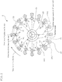
- FIG. 1 shows a schematic view of an embossing device according to one embodiment of the present invention.
- the embossing device 1 of this embodiment has a configuration in which, on a base 11, a can barrel supply turret 12, a heating turret 13, a can barrel transfer turret 14, an embossing turret 2 which conducts embossing on a can barrel 101, a can barrel transportation turret 15 or the like.
- the can barrel supply turret 12 supplies the can barrel 101 to a heating turret 13.
- the heating turret 13 has a high-frequency coil 131, and heats the can barrel 101 while allowing it to be rotated on its axis. As a result, damage or peeling by embossing of a coating, a film or the like of the inner surface or the outer surface of the can barrel 101 can be effectively prevented.
- the heating turret 13 may supply the can barrel 101 to the can barrel turret 14 after positioning by detecting a match mark 102 of the can barrel 101.
- the can barrel 101 which has been positioned is transported in the state that the rotation on its axis is stopped.
- the can barrel 101 slightly rotates by transfer or the like at the can barrel transfer turret 14, it is supplied to the embossing turret 2 in the state that it directs to almost the fixed range direction. Therefore, the time required for positioning in the embossing turret 2 is shortened, and a high-speed operation becomes possible. As a result, the productive capacity of the embossing device 1 can be enhanced.
- the can barrel transfer turret 14 supplies the can barrel 101 which has been heated and positioned to the embossing turret 2.
- FIG. 2 is a schematic view for explaining the relationship between the inner roll, the outer roll and the can barrel of the embossing device according to one embodiment of the present invention.
- the embossing turret 2 has a configuration in which a plurality of inner rolls 31 and outer rolls 32 (respectively 16 in this embodiment), a holding means 4 provided such that it corresponds to each inner roll 31, a stepping motor 43 provided in each holding means 4, a sensor 45 provided in each holding means 4, an encoder 22 which is attached to a rotational shaft 21, a rotational positioning controller 5 for controlling the stepping motor 43 or the like are provided.
- the embossing turret 2 of this embodiment differs from the embossing part (embossing turret) disclosed in the above-mentioned Patent Document 3 in that it is provided with the encoder 22 and the rotational positioning controller 5.
- Other configurations of the embossing turret 2 are almost similar to those of the above-mentioned embossing part, and hence, a detailed explanation thereof is omitted.
- the inner roll 31 and the outer roll 32 are arranged at an equal interval around the rotational shaft 21, and are respectively attached to the two shafts which rotate in a synchronized manner with the rotational shaft 21 by a planet gear.
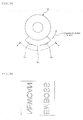
- FIG. 3A is a schematic plan view for explaining the outer roll of the embossing device according to one embodiment of the present invention.
- FIG. 3B is a schematic view for explaining the outer roll of the embossing device according to one embodiment of the present invention, showing a developmental view taken by an arrow A-A.
- the outer roll 32 has two embossing regions (that is, a first embossing region 33 and a second embossing region 34) which are distant from each other in a circumferential direction with a non-shaped section 35 being therebetween.
- a convex part corresponding to the character "EMBOSS” is formed
- a convex part corresponding to the character "NEWCAN” is formed.
- the inner roll 31 has two embossing regions which are distant from each other in a circumferential direction.
- a concave part corresponding to the character "EMBOSS” is formed, and in the second embossing region, a concave part corresponding to the character "NEWCAN" is formed.
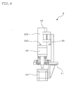
- FIG. 4 shows a schematic side view of the holding means of the embossing turret of the embossing device according to one embodiment of the present invention.
- the holding means 4 is provided with a base 41, a chuck 42, a stepping motor 43, a can pocket (can-supporting means) 44, a sensor 45 and the like.
- the base 41 is arranged at an equal interval around the rotational shaft 21, and is attached to a shaft which swings in a synchronized manner with the rotational shaft 21 by a cam mechanism. Specifically, the base 41 moves as follows: It contacts and retracts the inner roll 31 by a sliding body, a sliding cam mechanism or the like. Further, by a cam mechanism for swing movement using the cam element 23, it swings in a direction in which the can barrel 101 is pushed to the inner roll 31.
- the chuck 42 has an almost cylindrical shape, and a magnet or the like is embedded in the upper surface thereof.
- This chuck 42 is rotatably attached to the base 41, and rotates by means of the stepping motor 43 as the driving means.
- the can pocket 44 has a plurality of can barrel mounting rollers, magnets and the like.
- the sensor 45 is attached to the supporting member for the can pocket 44, and detects the match mark 102 of the can barrel 101 which is held by the chuck 42.
- the holding means 4 with the above-mentioned mechanism revolves around the rotational shaft 21 while conducting the predetermined contacting and retracting movements and swing movement, and holds the can barrel 101 such that its can rotate on its axis. Further, the stepping motor 43 allows the can barrel 101 which is held by the chuck 42 to rotate on its axis.
- the stepping motor 43 is used in order to allow the can barrel 101 to rotate.
- the means to rotate the can barrel 101 is not limited to the stepping motor 43.
- a servo motor, a motor provided with an encoder or the like which can control the rotation speed can be used.
- the can barrel 101 of this embodiment has a bottomed cylindrical shape, and has a rectangular match mark 102 at one location of the side.
- the shape or quantity of the match mark 102 is not limited to those mentioned above.
- the can barrel 101 is described as the can barrel for a two-piece can, but the application of the can barrel 101 is not limited to a two-piece can.
- the can barrel 101 can also be applied to a three-piece can in which a can bottom is provided at one side of the barrel.
- the encoder 22 is attached to the rotational shaft 21, and normally, an encoder having a dissolving power of several hundreds to several thousands pulses is used. In this embodiment, by attaching the encoder 22 to the rotational shaft 21, almost all controls can be conducted by the output pulse of the encoder 22.
- FIG. 5 is a schematic block diagram for explaining a rotational positioning controller of an embossing turret of the embossing device according to one embodiment of the present invention.
- the rotational positioning controller 5 receives detection signals from the sensor 45 and signals from the encoder 22 (Z-phase pulse signals and pulse signals), and based on these signals, control pulse signals are output to the driver 46, and the driver 46 controls the stepping motor 43.
- the rotational positioning controller 5 has a calculation processing part 51, a machine position detection part 52 and a pulse control part 53.
- the calculation processing part 51 has a CPU (central processing unit) or the like, and is connected with the machine position detection part 52, the pulse control part 53 and the sensor 45. This calculation processing part 51 occasionally receives the positional (machine angle) information of the corresponding inner roll 31. Further, when it receives from the sensor 45 detection signals that the match mark 102 has been detected, it obtains the amount of positional variations of the can barrel 101 which is held, and outputs control information for correcting the amount of variations to the pulse control part 53.
- CPU central processing unit
- the machine position detection part 52 receives Z-phase pulse signals and pulse signals from the encoder 22, and by counting pulse signals after receiving the Z-phase pulse signals, the position of the inner roll 31 (machine angle) is calculated. This machine position detection part 52 outputs the position (machine angle) information or the like of the inner roll 31, which has been calculated, to the calculation processing part 51.
- the pulse control part 53 as the driving means control part when it receives from the calculation processing part 51 control information for correcting the amount of positional variations, outputs control pulse signals to the driver 46 based on this control information.
- the driver 46 controls the rotation speed on its axis of the stepping motor 43, whereby the positional correction of the can barrel 101 is conducted.
- pulse signals of the encoder 22 can be used for generation of control pulse signals, whereby reliability or the like of the control system can be improved.
- the embossing turret 2 can conduct all controls by the output pulse from the rotational shaft 21 (pulse signals from the encoder 22). As a result, positioning control can be conducted easily and without fail by inputting numerical values to the operation means (not shown) of the rotational positioning controller 5. Therefore, the control operation time required to align the shaping position to the design can be significantly reduced, whereby productivity can be increased.
- the can barrel transportation turret 15 discharges the can barrel 101 which has been embossed by means of the embossing turret 2.
- the embossing method of this embodiment is a method of embossing the can barrel 101 using the embossing turret 2 of the above-mentioned embossing device 1.
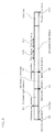
- FIG. 6 is a schematic view for explaining an embossing method according to one embodiment of the present invention.
- the can barrel 101 is supplied to the embossing turret 2 from the can barrel transfer turret 14. That is, at the point (a) shown in FIG. 2 , the embossing turret 2 receives the can barrel 101 from the can barrel transfer turret 14 (Step S1). At this time, the machine position detection part 52 of the rotational positioning controller 5 has counted the number of pulse signals after inputting Z-phase pulse signals. In the meantime, when the embossing turret 2 rotates by 360°, the number of pulse signals counted is 4000. Therefore, the number of pulse signals is 500.
- the rotational positioning controller 5 keeps the state in which the control pulse signals are not output to the driver 46. That is, the state in which the stepping motor 43 is stopped (the state in which the rotation on its axis of the can barrel 101 is stopped) is maintained (Step S2). By keeping the state in which the stepping motor 43 is stopped, the holding means 4 can hold the can barrel 101, which has been supplied, without fail.
- the can barrel 101 which is held, revolves to the point (b) shown in FIG. 2 , and reaches the position at which the positioning starts (Step S3).
- the number of pulse signals counted by the machine position detecting part 52 is 750.
- the positioning start position and the positioning position which will be mentioned later, are setting parameters, and hence, are set according to the processing speed or the like.
- the rotational positioning controller 5 outputs to the driver 46 control pulse signals for allowing the can barrel 101 to rotate on its axis at the same circumference speed as that of the circumference speed of the rotation on its axis of the inner roll 31.
- the stepping motor 43 rotates, and the can barrel 101, which is held, rotates at the same circumference speed as that of the circumference speed of the rotation on its axis of the inner roll 31 (Step S4).
- the state in which the can barrel 101 rotates at the same circumference speed as that of the circumference speed of the rotation on its axis of the inner roll 31 is called as the "same speed operation".
- the sensor 45 detects the match mark 102 on the can barrel 101 which rotates at the same circumference speed as that of the circumference speed of the rotation on its axis of the inner roll 31 (that is, which operates at the same speed") (Step S5), and then outputs the detection signals to the calculation processing part 51 of the rotational positioning controller 5.
- the calculation processing part 51 upon receipt of the detection signals, obtains the amount of positional variations of the can barrel 101 based on the positional (machine angle) information of the inner roll 31 from the machine position detection part 52. Then, control information for correcting the amount of positional variations is output to the pulse control part 53. Subsequently, upon receipt of control information for correcting the amount of positional variations from the calculation processing part 51, the pulse control part 53 outputs pulse signals for control to the driver 46 based on this control information. As a result, the driver 46 controls the speed of the rotation on its axis of the stepping motor 43, whereby the correction of the position of the can barrel 101 is conducted (Step S6).
- the calculation processing part 51 confirms that the match mark 102 is detected by the sensor 45 at the point (c) shown in FIG. 2 based on the positional (machine angle) information of the inner roll 31 from the machine position detection part 52 (normally, the number of pulse signals counted by the machine position detection part 52 (for example, 910)) at the time of receiving detection signals.
- the calculation processing part 51 can obtain the amount of positional variations. That is, in the case of the ideal state suffering no positional variations, the number of pulse signals counted should be 1000. However, the calculation processing part 52 receives detection signals when the number of pulse signals counted is 910. Therefore, the amount of positional variations is an amount corresponding to the number of counted signals of 90 in the advance direction.
- the calculation processing part 51 outputs to the pulse control part 53 control information for correcting the amount of positional variations corresponding to the number of counted signals of 90 in the advance direction, i.e. control signals for slowing the rotation speed of the stepping motor 43.
- the driver 46 slows down the revolution speed of the stepping motor 43, whereby the positional correction of the can barrel 101 is conducted.
- the positional correction of the can barrel 101 may be conducted by increasing the rotational speed of the stepping motor 43.
- the can barrel 101 which rotates on its axis by the stepping motor 43 revolves to the point (d) shown in FIG. 2 , and reaches the positioning position (Step S7). At this time, the number of pulse signals counted by the machine position detection part 52 is 1500.
- the rotational positioning controller 5 conducts positioning from the predetermined positioning start position to the predetermined positioning position while allowing the can barrel 101 to rotate on its axis, and it does not stop the rotation on its axis of the can barrel 101 from the predetermined positioning start position to the predetermined positioning position. Therefore, a defect that the positioning accuracy is lowered by suddenly switching from the halt state to the same speed operation can be avoided.
- the rotational positioning controller 5 allows the can barrel 101 to rotate on its axis at the same circumference speed as that of the circumference speed of the rotation on its axis of the inner roll 31.
- the rotational speed of the stepping motor 43 is controlled, whereby the position of the can barrel 101 is corrected.
- the rotational positioning controller 5 may obtain the amount of positional variations (error in positioning) based on signals from the sensor 45 which has detected the mach mark 102 in the vicinity of the above-mentioned positioning position, thereby to confirm that the amount of positional variations is less than the predetermined threshold value (Step S8). If the amount of positional variations exceeds the predetermined threshold value, the rotational positioning controller 5 may output emergency signals. In this way, the positioning state before shaping can be confirmed, whereby the reliability of quality can be increased.
- the rotational positioning controller 5 outputs to the driver 46 control pulse signals for allowing the can barrel 101 to rotate on its axis at the same circumference speed as that of the circumference speed of the rotation on its axis of the inner roll 31.
- the stepping motor 43 rotates, and the can barrel 101, which is held, rotates at the same circumference speed as that of the circumference speed of the inner roll 31 in the state in which the position has been corrected (that is, the state suffering almost no positional variations) (Step S9).
- the first processing is conducted (Step S10). Further, the second processing is conducted (Step S11).
- the number of pulse signals counted by the machine position detection part 52 at the point (e) is 1750
- the number of pulse signals counted by the machine position detection part 52 at the point (f) is 2250.
- the embossing turret 2 of this embodiment can conduct embossing on the can barrel 101 in the state where the can barrel 101 is position-corrected (the state which suffers almost no positional variations) and in the state where the can barrel 101 rotates on its axis at the same circumference speed as that of those of the inner roll 31 and the outer roll 32 ("synchronized movement state").
- the inner roll 31 and the outer roll 32 of this embodiment has two embossing regions which are distant from each other with the non-shaped section 35 therebetween (that is, the first embossing region 33 and the second embossing region 34), and hence, the embossing turret 2 can produce double-embossed surface cans which conventionally could not be produced.
- the can barrel 101 which is held, is allowed to move in a synchronized manner to the point (g) shown in FIG. 2 .
- the rotational positioning controller 5 keeps the state where the control pulse signals are not output to the driver 46. That is, the state where the stepping motor 43 is halted (the state in which the rotation on its axis of the can barrel 101 is halted) is maintained (Step S12).
- the embossing turret 2 supplies the embossed can barrel 101 to the can barrel transportation turret 15. That is, the embossing turret 2, at the point (h) shown in FIG. 2 , transfers the can barrel 101 to the can barrel transportation turret 15 (Step S13). At this time, the number of pulse signals counted by the machine detection part 52 is 3500.
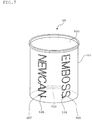
- FIG. 7 is a schematic perspective view of the embossed can according to one embodiment of the present invention.
- the embossed can 10 has the can barrel 101 and a can lid 103.
- This embossed can 10 is a double-embossed surface can, which is obtained by embossing by using the embossing device 1 and the embossing method as mentioned above.
- the first pattern 104 (“EMBOSS”) is printed, and the first concave portion 105 (“EMBOSS”) is formed in the state that it is so positioned as to almost conform to the first pattern 104.
- the second pattern 106 (“NEWCAN”) is printed, and the second concave portion 107 (“NEWCAN”) is formed in the state that it is so positioned as to almost conform to the second pattern 106.
- the embossing method and the embossed can 10 according to this embodiment, it is possible to conduct embossing having a non-shaped section and an arbitral number of embossing regions, whereby the quality or productivity can be improved.
- the embossed can 10 which is a double-embossed surface can is able to have an innovative design, whereby additive value can be improved.
- the embossing device, the embossing method and the embossed can of the present invention were explained with reference to preferred embodiments.
- the embossing device, the embossing method and the embossed can of the present invention are not limited to the above-mentioned embodiments or the like. It is needless to say various modifications are possible within the scope of the present invention as set out in the appended claims.
- the present invention can be applied to other processing which requires accurate rotational positioning of the can barrel while allowing the can barrel to rotate on its axis at a predetermined speed.
Landscapes
- Engineering & Computer Science (AREA)
- Mechanical Engineering (AREA)
- Automation & Control Theory (AREA)
- Shaping Metal By Deep-Drawing, Or The Like (AREA)
- Details Of Rigid Or Semi-Rigid Containers (AREA)
- Shaping Of Tube Ends By Bending Or Straightening (AREA)
Applications Claiming Priority (2)
| Application Number | Priority Date | Filing Date | Title |
|---|---|---|---|
| JP2009136094A JP5428549B2 (ja) | 2009-06-05 | 2009-06-05 | エンボス加工装置及びエンボス加工方法 |
| PCT/JP2010/003588 WO2010140327A1 (ja) | 2009-06-05 | 2010-05-28 | エンボス加工装置、エンボス加工方法、及び、エンボス缶 |
Publications (3)
| Publication Number | Publication Date |
|---|---|
| EP2439006A1 EP2439006A1 (en) | 2012-04-11 |
| EP2439006A4 EP2439006A4 (en) | 2017-03-15 |
| EP2439006B1 true EP2439006B1 (en) | 2018-02-28 |
Family
ID=43297470
Family Applications (1)
| Application Number | Title | Priority Date | Filing Date |
|---|---|---|---|
| EP10783115.8A Not-in-force EP2439006B1 (en) | 2009-06-05 | 2010-05-28 | Embossing device and embossing method |
Country Status (5)
| Country | Link |
|---|---|
| US (1) | US9003851B2 (enExample) |
| EP (1) | EP2439006B1 (enExample) |
| JP (1) | JP5428549B2 (enExample) |
| CN (1) | CN102458706B (enExample) |
| WO (1) | WO2010140327A1 (enExample) |
Families Citing this family (11)
| Publication number | Priority date | Publication date | Assignee | Title |
|---|---|---|---|---|
| CN107187258B (zh) * | 2015-03-09 | 2018-11-06 | 罗帮亮 | 压制形状精度较高的自动压花设备及其工作方法 |
| US11898628B2 (en) | 2015-11-30 | 2024-02-13 | Victaulic Company | Cam grooving machine |
| WO2017095692A1 (en) | 2015-11-30 | 2017-06-08 | Victaulic Company | Sprinkler adapter and pipe plug |
| KR102158950B1 (ko) | 2015-11-30 | 2020-09-23 | 빅톨릭 컴패니 | 캠식 홈가공기 |
| KR101737599B1 (ko) * | 2017-01-11 | 2017-05-19 | 피엔에스테크놀러지(주) | 캔 검사장치 |
| CN106925650B (zh) * | 2017-04-18 | 2019-07-16 | 苏州斯莱克精密设备股份有限公司 | 一种罐体压花机 |
| US10525516B2 (en) | 2017-05-03 | 2020-01-07 | Victaulic Company | Cam grooving machine with cam stop surfaces |
| US10960450B2 (en) | 2017-12-19 | 2021-03-30 | Victaulic Company | Pipe grooving device |
| CN119237549A (zh) | 2019-08-21 | 2025-01-03 | 唯特利公司 | 用于管开槽装置的管接收组件 |
| US11759839B2 (en) | 2020-09-24 | 2023-09-19 | Victaulic Company | Pipe grooving device |
| CN112678757A (zh) * | 2020-12-31 | 2021-04-20 | 深圳市春晖国际货运代理有限公司 | 一种饮料罐的输送及打码装置 |
Family Cites Families (10)
| Publication number | Priority date | Publication date | Assignee | Title |
|---|---|---|---|---|
| US5799525A (en) * | 1996-07-19 | 1998-09-01 | Aluminum Company Of America | Tooling and method for the embossing of a container and the resulting container |
| CN1112993C (zh) * | 1999-05-17 | 2003-07-02 | 伯格利-格拉维瑞斯股份有限公司 | 用于片材轧花的装置、及其应用、制造方法和操作方法 |
| US6338263B1 (en) * | 1999-06-30 | 2002-01-15 | Toyo Seikan Kaisha, Ltd. | Method for manufacturing embossed can body, inspecting apparatus used for manufacturing embossed can body, and inspecting method used therefor |
| JP3478181B2 (ja) | 1999-06-30 | 2003-12-15 | 東洋製罐株式会社 | 缶 体 |
| JP3478185B2 (ja) | 1999-07-19 | 2003-12-15 | 東洋製罐株式会社 | エンボス加工缶体の製造方法 |
| JP3900398B2 (ja) | 1999-08-12 | 2007-04-04 | 大和製罐株式会社 | 缶胴の印刷デザイン位置合わせ方法および装置 |
| DE10216139C1 (de) * | 2002-04-12 | 2003-12-11 | Kurz Leonhard Fa | Prägevorrichtung |
| DE10226500B4 (de) * | 2002-06-14 | 2010-04-22 | Ball Packaging Europe Holding Gmbh & Co. Kg | Vorrichtung zur Oberflächenbearbeitung von Teilen |
| JP4916516B2 (ja) * | 2007-10-04 | 2012-04-11 | 武内プレス工業株式会社 | 加飾容器の製造方法 |
| JP4775424B2 (ja) | 2008-09-26 | 2011-09-21 | 東洋製罐株式会社 | 缶胴の加工方法 |
-
2009
- 2009-06-05 JP JP2009136094A patent/JP5428549B2/ja active Active
-
2010
- 2010-05-28 EP EP10783115.8A patent/EP2439006B1/en not_active Not-in-force
- 2010-05-28 WO PCT/JP2010/003588 patent/WO2010140327A1/ja not_active Ceased
- 2010-05-28 US US13/375,916 patent/US9003851B2/en active Active
- 2010-05-28 CN CN201080024388.9A patent/CN102458706B/zh active Active
Non-Patent Citations (1)
| Title |
|---|
| None * |
Also Published As
| Publication number | Publication date |
|---|---|
| EP2439006A4 (en) | 2017-03-15 |
| JP2010279977A (ja) | 2010-12-16 |
| EP2439006A1 (en) | 2012-04-11 |
| CN102458706B (zh) | 2014-10-15 |
| US20120074018A1 (en) | 2012-03-29 |
| US9003851B2 (en) | 2015-04-14 |
| WO2010140327A1 (ja) | 2010-12-09 |
| JP5428549B2 (ja) | 2014-02-26 |
| CN102458706A (zh) | 2012-05-16 |
Similar Documents
| Publication | Publication Date | Title |
|---|---|---|
| EP2439006B1 (en) | Embossing device and embossing method | |
| EP2687383B1 (en) | Embossing a flat metal blank (method and apparatus) | |
| KR101508108B1 (ko) | 스피닝 성형 장치 및 성형 방법 | |
| CN112635350B (zh) | 一种夹持式晶圆校准装置及校准方法 | |
| EP3515710B1 (en) | Apparatus for registered foil stamping and process | |
| US8632333B2 (en) | Apparatus and method for handling a container product | |
| JP2619148B2 (ja) | 金属コイルに模様を施す方法及び装置 | |
| JP2009028792A (ja) | 缶胴の加工方法 | |
| US20080060535A1 (en) | Method for inline die cutting that compensates for image variances | |
| EP3112175B1 (en) | Process and apparatus for digital printing on articles | |
| JP3823952B2 (ja) | エンボス加工缶体の製造方法 | |
| CN116873344B (zh) | 瓶体角度调整装置及瓶体角度调整方法 | |
| CN220391725U (zh) | 瓶体角度调整装置 | |
| JP3900398B2 (ja) | 缶胴の印刷デザイン位置合わせ方法および装置 | |
| JP4305074B2 (ja) | 缶胴の加工方法及び加工装置 | |
| US9880074B2 (en) | Pressing load setting method of tire testing machine | |
| CN112277461B (zh) | 一种高精度印刷定位装置 | |
| JP2011005512A (ja) | エンボス加工装置、エンボス加工方法、及び、エンボス缶 | |
| JP2010264481A (ja) | エンボス成形方法およびその装置 | |
| JP3478181B2 (ja) | 缶 体 | |
| JP2004255392A (ja) | エンボス加工缶体の製造方法および缶胴の位置合わせ方法 | |
| WO1999056971A1 (en) | Metal coil printing and pressing registration control | |
| JP7711574B2 (ja) | 研削盤 | |
| JPH0815783B2 (ja) | 転写装置 | |
| JP2005021925A (ja) | 缶本体の製造装置及び缶本体の製造方法並びに缶本体及び缶 |
Legal Events
| Date | Code | Title | Description |
|---|---|---|---|
| PUAI | Public reference made under article 153(3) epc to a published international application that has entered the european phase |
Free format text: ORIGINAL CODE: 0009012 |
|
| 17P | Request for examination filed |
Effective date: 20111125 |
|
| AK | Designated contracting states |
Kind code of ref document: A1 Designated state(s): AL AT BE BG CH CY CZ DE DK EE ES FI FR GB GR HR HU IE IS IT LI LT LU LV MC MK MT NL NO PL PT RO SE SI SK SM TR |
|
| RAP1 | Party data changed (applicant data changed or rights of an application transferred) |
Owner name: TOYO SEIKAN KAISHA, LTD. |
|
| DAX | Request for extension of the european patent (deleted) | ||
| RA4 | Supplementary search report drawn up and despatched (corrected) |
Effective date: 20170209 |
|
| RIC1 | Information provided on ipc code assigned before grant |
Ipc: B21D 22/02 20060101ALI20170203BHEP Ipc: B65D 25/20 20060101ALI20170203BHEP Ipc: B21D 22/08 20060101AFI20170203BHEP Ipc: B21D 51/26 20060101ALI20170203BHEP Ipc: B44B 5/02 20060101ALI20170203BHEP |
|
| GRAP | Despatch of communication of intention to grant a patent |
Free format text: ORIGINAL CODE: EPIDOSNIGR1 |
|
| STAA | Information on the status of an ep patent application or granted ep patent |
Free format text: STATUS: GRANT OF PATENT IS INTENDED |
|
| RIC1 | Information provided on ipc code assigned before grant |
Ipc: B44B 5/02 20060101ALI20170927BHEP Ipc: B65D 25/20 20060101ALI20170927BHEP Ipc: B21D 22/02 20060101ALI20170927BHEP Ipc: B21D 51/26 20060101ALI20170927BHEP Ipc: B21D 22/08 20060101AFI20170927BHEP |
|
| INTG | Intention to grant announced |
Effective date: 20171020 |
|
| GRAS | Grant fee paid |
Free format text: ORIGINAL CODE: EPIDOSNIGR3 |
|
| GRAA | (expected) grant |
Free format text: ORIGINAL CODE: 0009210 |
|
| STAA | Information on the status of an ep patent application or granted ep patent |
Free format text: STATUS: THE PATENT HAS BEEN GRANTED |
|
| AK | Designated contracting states |
Kind code of ref document: B1 Designated state(s): AL AT BE BG CH CY CZ DE DK EE ES FI FR GB GR HR HU IE IS IT LI LT LU LV MC MK MT NL NO PL PT RO SE SI SK SM TR |
|
| RAP1 | Party data changed (applicant data changed or rights of an application transferred) |
Owner name: TOYO SEIKAN GROUP HOLDINGS, LTD. |
|
| REG | Reference to a national code |
Ref country code: GB Ref legal event code: FG4D Ref country code: CH Ref legal event code: EP |
|
| REG | Reference to a national code |
Ref country code: AT Ref legal event code: REF Ref document number: 973561 Country of ref document: AT Kind code of ref document: T Effective date: 20180315 |
|
| REG | Reference to a national code |
Ref country code: IE Ref legal event code: FG4D |
|
| REG | Reference to a national code |
Ref country code: DE Ref legal event code: R096 Ref document number: 602010048855 Country of ref document: DE |
|
| REG | Reference to a national code |
Ref country code: CH Ref legal event code: NV Representative=s name: ISLER AND PEDRAZZINI AG, CH |
|
| REG | Reference to a national code |
Ref country code: NL Ref legal event code: MP Effective date: 20180228 |
|
| REG | Reference to a national code |
Ref country code: LT Ref legal event code: MG4D |
|
| REG | Reference to a national code |
Ref country code: AT Ref legal event code: MK05 Ref document number: 973561 Country of ref document: AT Kind code of ref document: T Effective date: 20180228 |
|
| PG25 | Lapsed in a contracting state [announced via postgrant information from national office to epo] |
Ref country code: LT Free format text: LAPSE BECAUSE OF FAILURE TO SUBMIT A TRANSLATION OF THE DESCRIPTION OR TO PAY THE FEE WITHIN THE PRESCRIBED TIME-LIMIT Effective date: 20180228 Ref country code: CY Free format text: LAPSE BECAUSE OF FAILURE TO SUBMIT A TRANSLATION OF THE DESCRIPTION OR TO PAY THE FEE WITHIN THE PRESCRIBED TIME-LIMIT Effective date: 20180228 Ref country code: HR Free format text: LAPSE BECAUSE OF FAILURE TO SUBMIT A TRANSLATION OF THE DESCRIPTION OR TO PAY THE FEE WITHIN THE PRESCRIBED TIME-LIMIT Effective date: 20180228 Ref country code: NL Free format text: LAPSE BECAUSE OF FAILURE TO SUBMIT A TRANSLATION OF THE DESCRIPTION OR TO PAY THE FEE WITHIN THE PRESCRIBED TIME-LIMIT Effective date: 20180228 Ref country code: NO Free format text: LAPSE BECAUSE OF FAILURE TO SUBMIT A TRANSLATION OF THE DESCRIPTION OR TO PAY THE FEE WITHIN THE PRESCRIBED TIME-LIMIT Effective date: 20180528 Ref country code: ES Free format text: LAPSE BECAUSE OF FAILURE TO SUBMIT A TRANSLATION OF THE DESCRIPTION OR TO PAY THE FEE WITHIN THE PRESCRIBED TIME-LIMIT Effective date: 20180228 Ref country code: FI Free format text: LAPSE BECAUSE OF FAILURE TO SUBMIT A TRANSLATION OF THE DESCRIPTION OR TO PAY THE FEE WITHIN THE PRESCRIBED TIME-LIMIT Effective date: 20180228 |
|
| PG25 | Lapsed in a contracting state [announced via postgrant information from national office to epo] |
Ref country code: AT Free format text: LAPSE BECAUSE OF FAILURE TO SUBMIT A TRANSLATION OF THE DESCRIPTION OR TO PAY THE FEE WITHIN THE PRESCRIBED TIME-LIMIT Effective date: 20180228 Ref country code: LV Free format text: LAPSE BECAUSE OF FAILURE TO SUBMIT A TRANSLATION OF THE DESCRIPTION OR TO PAY THE FEE WITHIN THE PRESCRIBED TIME-LIMIT Effective date: 20180228 Ref country code: SE Free format text: LAPSE BECAUSE OF FAILURE TO SUBMIT A TRANSLATION OF THE DESCRIPTION OR TO PAY THE FEE WITHIN THE PRESCRIBED TIME-LIMIT Effective date: 20180228 Ref country code: GR Free format text: LAPSE BECAUSE OF FAILURE TO SUBMIT A TRANSLATION OF THE DESCRIPTION OR TO PAY THE FEE WITHIN THE PRESCRIBED TIME-LIMIT Effective date: 20180529 Ref country code: BG Free format text: LAPSE BECAUSE OF FAILURE TO SUBMIT A TRANSLATION OF THE DESCRIPTION OR TO PAY THE FEE WITHIN THE PRESCRIBED TIME-LIMIT Effective date: 20180528 |
|
| PG25 | Lapsed in a contracting state [announced via postgrant information from national office to epo] |
Ref country code: PL Free format text: LAPSE BECAUSE OF FAILURE TO SUBMIT A TRANSLATION OF THE DESCRIPTION OR TO PAY THE FEE WITHIN THE PRESCRIBED TIME-LIMIT Effective date: 20180228 Ref country code: AL Free format text: LAPSE BECAUSE OF FAILURE TO SUBMIT A TRANSLATION OF THE DESCRIPTION OR TO PAY THE FEE WITHIN THE PRESCRIBED TIME-LIMIT Effective date: 20180228 Ref country code: EE Free format text: LAPSE BECAUSE OF FAILURE TO SUBMIT A TRANSLATION OF THE DESCRIPTION OR TO PAY THE FEE WITHIN THE PRESCRIBED TIME-LIMIT Effective date: 20180228 Ref country code: RO Free format text: LAPSE BECAUSE OF FAILURE TO SUBMIT A TRANSLATION OF THE DESCRIPTION OR TO PAY THE FEE WITHIN THE PRESCRIBED TIME-LIMIT Effective date: 20180228 |
|
| REG | Reference to a national code |
Ref country code: DE Ref legal event code: R097 Ref document number: 602010048855 Country of ref document: DE |
|
| PG25 | Lapsed in a contracting state [announced via postgrant information from national office to epo] |
Ref country code: SK Free format text: LAPSE BECAUSE OF FAILURE TO SUBMIT A TRANSLATION OF THE DESCRIPTION OR TO PAY THE FEE WITHIN THE PRESCRIBED TIME-LIMIT Effective date: 20180228 Ref country code: SM Free format text: LAPSE BECAUSE OF FAILURE TO SUBMIT A TRANSLATION OF THE DESCRIPTION OR TO PAY THE FEE WITHIN THE PRESCRIBED TIME-LIMIT Effective date: 20180228 Ref country code: CZ Free format text: LAPSE BECAUSE OF FAILURE TO SUBMIT A TRANSLATION OF THE DESCRIPTION OR TO PAY THE FEE WITHIN THE PRESCRIBED TIME-LIMIT Effective date: 20180228 Ref country code: DK Free format text: LAPSE BECAUSE OF FAILURE TO SUBMIT A TRANSLATION OF THE DESCRIPTION OR TO PAY THE FEE WITHIN THE PRESCRIBED TIME-LIMIT Effective date: 20180228 |
|
| PLBE | No opposition filed within time limit |
Free format text: ORIGINAL CODE: 0009261 |
|
| STAA | Information on the status of an ep patent application or granted ep patent |
Free format text: STATUS: NO OPPOSITION FILED WITHIN TIME LIMIT |
|
| GBPC | Gb: european patent ceased through non-payment of renewal fee |
Effective date: 20180528 |
|
| REG | Reference to a national code |
Ref country code: BE Ref legal event code: MM Effective date: 20180531 |
|
| PG25 | Lapsed in a contracting state [announced via postgrant information from national office to epo] |
Ref country code: MC Free format text: LAPSE BECAUSE OF FAILURE TO SUBMIT A TRANSLATION OF THE DESCRIPTION OR TO PAY THE FEE WITHIN THE PRESCRIBED TIME-LIMIT Effective date: 20180228 |
|
| 26N | No opposition filed |
Effective date: 20181129 |
|
| REG | Reference to a national code |
Ref country code: IE Ref legal event code: MM4A |
|
| PG25 | Lapsed in a contracting state [announced via postgrant information from national office to epo] |
Ref country code: SI Free format text: LAPSE BECAUSE OF FAILURE TO SUBMIT A TRANSLATION OF THE DESCRIPTION OR TO PAY THE FEE WITHIN THE PRESCRIBED TIME-LIMIT Effective date: 20180228 |
|
| PG25 | Lapsed in a contracting state [announced via postgrant information from national office to epo] |
Ref country code: LU Free format text: LAPSE BECAUSE OF NON-PAYMENT OF DUE FEES Effective date: 20180528 |
|
| PG25 | Lapsed in a contracting state [announced via postgrant information from national office to epo] |
Ref country code: GB Free format text: LAPSE BECAUSE OF NON-PAYMENT OF DUE FEES Effective date: 20180528 Ref country code: FR Free format text: LAPSE BECAUSE OF NON-PAYMENT OF DUE FEES Effective date: 20180531 Ref country code: IE Free format text: LAPSE BECAUSE OF NON-PAYMENT OF DUE FEES Effective date: 20180528 |
|
| PG25 | Lapsed in a contracting state [announced via postgrant information from national office to epo] |
Ref country code: BE Free format text: LAPSE BECAUSE OF NON-PAYMENT OF DUE FEES Effective date: 20180531 |
|
| PGFP | Annual fee paid to national office [announced via postgrant information from national office to epo] |
Ref country code: CH Payment date: 20190521 Year of fee payment: 10 |
|
| PG25 | Lapsed in a contracting state [announced via postgrant information from national office to epo] |
Ref country code: MT Free format text: LAPSE BECAUSE OF NON-PAYMENT OF DUE FEES Effective date: 20180528 |
|
| PG25 | Lapsed in a contracting state [announced via postgrant information from national office to epo] |
Ref country code: TR Free format text: LAPSE BECAUSE OF FAILURE TO SUBMIT A TRANSLATION OF THE DESCRIPTION OR TO PAY THE FEE WITHIN THE PRESCRIBED TIME-LIMIT Effective date: 20180228 |
|
| PG25 | Lapsed in a contracting state [announced via postgrant information from national office to epo] |
Ref country code: PT Free format text: LAPSE BECAUSE OF FAILURE TO SUBMIT A TRANSLATION OF THE DESCRIPTION OR TO PAY THE FEE WITHIN THE PRESCRIBED TIME-LIMIT Effective date: 20180228 Ref country code: HU Free format text: LAPSE BECAUSE OF FAILURE TO SUBMIT A TRANSLATION OF THE DESCRIPTION OR TO PAY THE FEE WITHIN THE PRESCRIBED TIME-LIMIT; INVALID AB INITIO Effective date: 20100528 |
|
| PG25 | Lapsed in a contracting state [announced via postgrant information from national office to epo] |
Ref country code: MK Free format text: LAPSE BECAUSE OF NON-PAYMENT OF DUE FEES Effective date: 20180228 |
|
| PG25 | Lapsed in a contracting state [announced via postgrant information from national office to epo] |
Ref country code: IS Free format text: LAPSE BECAUSE OF FAILURE TO SUBMIT A TRANSLATION OF THE DESCRIPTION OR TO PAY THE FEE WITHIN THE PRESCRIBED TIME-LIMIT Effective date: 20180628 |
|
| PG25 | Lapsed in a contracting state [announced via postgrant information from national office to epo] |
Ref country code: CH Free format text: LAPSE BECAUSE OF NON-PAYMENT OF DUE FEES Effective date: 20200531 Ref country code: LI Free format text: LAPSE BECAUSE OF NON-PAYMENT OF DUE FEES Effective date: 20200531 |
|
| PGFP | Annual fee paid to national office [announced via postgrant information from national office to epo] |
Ref country code: DE Payment date: 20240521 Year of fee payment: 15 |
|
| PGFP | Annual fee paid to national office [announced via postgrant information from national office to epo] |
Ref country code: IT Payment date: 20240524 Year of fee payment: 15 |
|
| REG | Reference to a national code |
Ref country code: DE Ref legal event code: R119 Ref document number: 602010048855 Country of ref document: DE |
|
| PG25 | Lapsed in a contracting state [announced via postgrant information from national office to epo] |
Ref country code: DE Free format text: LAPSE BECAUSE OF NON-PAYMENT OF DUE FEES Effective date: 20251202 |
|
| PG25 | Lapsed in a contracting state [announced via postgrant information from national office to epo] |
Ref country code: IT Free format text: LAPSE BECAUSE OF NON-PAYMENT OF DUE FEES Effective date: 20250528 |