EP2438405B1 - Luftfahrzeugbrennstoffsfühlstandmessungs-vorrichtung und -verfahren - Google Patents
Luftfahrzeugbrennstoffsfühlstandmessungs-vorrichtung und -verfahren Download PDFInfo
- Publication number
- EP2438405B1 EP2438405B1 EP10722397.6A EP10722397A EP2438405B1 EP 2438405 B1 EP2438405 B1 EP 2438405B1 EP 10722397 A EP10722397 A EP 10722397A EP 2438405 B1 EP2438405 B1 EP 2438405B1
- Authority
- EP
- European Patent Office
- Prior art keywords
- fuel
- capacitance
- capacitive
- time
- output signal
- Prior art date
- Legal status (The legal status is an assumption and is not a legal conclusion. Google has not performed a legal analysis and makes no representation as to the accuracy of the status listed.)
- Active
Links
Images




Classifications
-
- G—PHYSICS
- G01—MEASURING; TESTING
- G01F—MEASURING VOLUME, VOLUME FLOW, MASS FLOW OR LIQUID LEVEL; METERING BY VOLUME
- G01F23/00—Indicating or measuring liquid level or level of fluent solid material, e.g. indicating in terms of volume or indicating by means of an alarm
- G01F23/22—Indicating or measuring liquid level or level of fluent solid material, e.g. indicating in terms of volume or indicating by means of an alarm by measuring physical variables, other than linear dimensions, pressure or weight, dependent on the level to be measured, e.g. by difference of heat transfer of steam or water
- G01F23/26—Indicating or measuring liquid level or level of fluent solid material, e.g. indicating in terms of volume or indicating by means of an alarm by measuring physical variables, other than linear dimensions, pressure or weight, dependent on the level to be measured, e.g. by difference of heat transfer of steam or water by measuring variations of capacity or inductance of capacitors or inductors arising from the presence of liquid or fluent solid material in the electric or electromagnetic fields
- G01F23/263—Indicating or measuring liquid level or level of fluent solid material, e.g. indicating in terms of volume or indicating by means of an alarm by measuring physical variables, other than linear dimensions, pressure or weight, dependent on the level to be measured, e.g. by difference of heat transfer of steam or water by measuring variations of capacity or inductance of capacitors or inductors arising from the presence of liquid or fluent solid material in the electric or electromagnetic fields by measuring variations in capacitance of capacitors
- G01F23/266—Indicating or measuring liquid level or level of fluent solid material, e.g. indicating in terms of volume or indicating by means of an alarm by measuring physical variables, other than linear dimensions, pressure or weight, dependent on the level to be measured, e.g. by difference of heat transfer of steam or water by measuring variations of capacity or inductance of capacitors or inductors arising from the presence of liquid or fluent solid material in the electric or electromagnetic fields by measuring variations in capacitance of capacitors measuring circuits therefor
-
- G—PHYSICS
- G01—MEASURING; TESTING
- G01F—MEASURING VOLUME, VOLUME FLOW, MASS FLOW OR LIQUID LEVEL; METERING BY VOLUME
- G01F23/00—Indicating or measuring liquid level or level of fluent solid material, e.g. indicating in terms of volume or indicating by means of an alarm
- G01F23/22—Indicating or measuring liquid level or level of fluent solid material, e.g. indicating in terms of volume or indicating by means of an alarm by measuring physical variables, other than linear dimensions, pressure or weight, dependent on the level to be measured, e.g. by difference of heat transfer of steam or water
- G01F23/26—Indicating or measuring liquid level or level of fluent solid material, e.g. indicating in terms of volume or indicating by means of an alarm by measuring physical variables, other than linear dimensions, pressure or weight, dependent on the level to be measured, e.g. by difference of heat transfer of steam or water by measuring variations of capacity or inductance of capacitors or inductors arising from the presence of liquid or fluent solid material in the electric or electromagnetic fields
- G01F23/263—Indicating or measuring liquid level or level of fluent solid material, e.g. indicating in terms of volume or indicating by means of an alarm by measuring physical variables, other than linear dimensions, pressure or weight, dependent on the level to be measured, e.g. by difference of heat transfer of steam or water by measuring variations of capacity or inductance of capacitors or inductors arising from the presence of liquid or fluent solid material in the electric or electromagnetic fields by measuring variations in capacitance of capacitors
- G01F23/265—Indicating or measuring liquid level or level of fluent solid material, e.g. indicating in terms of volume or indicating by means of an alarm by measuring physical variables, other than linear dimensions, pressure or weight, dependent on the level to be measured, e.g. by difference of heat transfer of steam or water by measuring variations of capacity or inductance of capacitors or inductors arising from the presence of liquid or fluent solid material in the electric or electromagnetic fields by measuring variations in capacitance of capacitors for discrete levels
-
- G—PHYSICS
- G01—MEASURING; TESTING
- G01N—INVESTIGATING OR ANALYSING MATERIALS BY DETERMINING THEIR CHEMICAL OR PHYSICAL PROPERTIES
- G01N33/00—Investigating or analysing materials by specific methods not covered by groups G01N1/00 - G01N31/00
- G01N33/26—Oils; Viscous liquids; Paints; Inks
- G01N33/28—Oils, i.e. hydrocarbon liquids
- G01N33/2835—Specific substances contained in the oils or fuels
- G01N33/2847—Water in oils
Definitions
- the present invention is concerned with an aircraft fuel tank fluid level measurement apparatus and method for measurement of fluid levels in aircraft fuel tanks. More specifically, the present invention is concerned with an aircraft wing fuel tank fuel, water and ice level measurement apparatus and method.
- Aircraft fuel tanks comprise vents in order to allow air in and out of the tank. This is because as the aircraft's altitude changes, the ambient pressure changes and therefore in order to avoid a significant pressure differential between the inside and outside of the fuel tank it is beneficial to allow ambient air to move in and out of the tank. This also allows air to replace the fuel used by the aircraft engines as the tank empties.
- a problem with venting aircraft fuel tanks is that moist air may be allowed into the tank.
- moist air When the moist air is cooled by a reduction in ambient temperature, the water in the air condenses to a liquid.
- Fuel levels in modern aircraft are often monitored using a capacitive fuel probe.
- Such probes comprise a pair of offset plates (normally in the shape of a pair of concentric cylinders) between which fuel can enter.
- the annular area between the plates which contains fuel also decreases. Because the dielectric constant of the fuel is significantly higher than that of air, the capacitance of the probe changes with the fuel level, and can be measured in a low power circuit to determine the fuel level.
- capacitive probes operate on the assumption that the dielectric constant of the fuel is known and is constant, and therefore the capacitance of the probe is proportional to the fuel level. This may not be the case, as the dielectric constant may change with the pressure and temperature of the fuel.
- the dielectric constant of the fuel can be measured by using the fuel as the dielectric in a capacitor of known dimensions and properties.
- a problem with this approach is that the measurement equipment adds complexity and weight to the aircraft fuel system.
- a further problem with known capacitive probes is that when the water level rises in the tank (as previously described) a stratified fluid develops in which the probe is partially immersed in water at its base, a layer of fuel on top of the water and the remainder in air. The reading of the probe is thus distorted because the dielectric constant of water (about 80 times that of air) is significantly higher than that of fuel. Therefore the probe will indicate a higher capacitance than the equivalent level of fuel alone and report that the tank contains more fuel than it actually does.
- Capacitive probes have a large working range as they need to be able to report the fuel level from an empty to a full tank. A probe partially immersed in water will therefore not always provide a reading outside of its working range, rather it will report an erroneously high fuel level. Therefore the error is not always detectable by out-of-range readings. This is further complicated by the introduction of other substances such as ice.
- the invention minimises wiring to the central fuel processing computer. Less wiring is advantageous in aircraft applications in order to minimise weight and interference. Further, by using the subject method, existing aircraft architecture may be used and the present invention retrofitted thereto.
- the first reference capacitor is positioned at a first end of the plurality of discrete capacitive sections, and a second reference capacitor is provided at a second end of the plurality of discrete capacitive sections.
- a capacitive probe 100 is installed within an aircraft wing fuel tank 102.
- the fuel tank 102 contains fuel 104 to a level L.
- the capacitive probe 100 comprises an outer cylindrical plate 106 and an inner cylindrical plate 108 which are concentric.
- the cylindrical plates 106, 108 define an annular capacitor 110.
- the probe 100 is not in contact with the tank 102 such that the fuel 104 can flow into, and out of, the capacitor 110.
- a pair of electrical contacts 112 are connected to the outer and inner plates 106, 108 for measurement of the capacitance of the probe 100 in a known fashion.
- the capacitance of the probe 100 changes because the dielectric constant of air (filling the tank space) is significantly lower than that of fuel. Therefore, the level L of the fuel 104 in the tank can be estimated providing the dielectric constant of the fuel 104 is known.
- dielectric constant of fuel must be either estimated (introducing inaccuracies in the reading) or measured (which requires additional equipment).
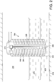
- the probe comprises a plurality of stacked annular sections 202, from 1 to "N" sections. Typically, N+1 is a power of 2 (e.g. 8, 16, 32, 64 etc.).
- Each section 202 comprises an outer plate 204 and a common inner plate 206 and each section 202 therefore acts independently as a capacitor.
- the outer plates 204 are etched onto the inner surface of a carrier (not shown).
- An axial gap 205 at a single circumferential position is formed in the outer plates 204.
- Each section 202 comprises its own set of contacts 208 etched into the carrier and routed through the gap 205 for use in measurement of its capacitance as will be described below.
- Each section 202 is identical, i.e. of equal height in the fuel fill direction, and equal diameter. Therefore each section can be assumed to have substantially the same capacitance properties when presented with the same dielectric substance.
- Each of the contacts is connected to a multiplexing circuit 210 which will be described below.
- a fuel tank 212 in which the probe 200 is installed contains a layer of water 214 condensed from ingested atmospheric air (as described above).
- the tank also contains a layer of fuel 216 and the remainder is filled with air 218.
- the water 214 sinks to the bottom of the tank 212 because it is denser than the fuel 216.
- the lowest of the annular sections 202 is completely immersed in water 214, the next of the annular sections 202 is partly immersed in water 214, and partly in fuel 216, the next three annular sections 202 are fully immersed in fuel 216, the next section is partly immersed in fuel 216 and partly immersed in the air 218, and the remaining sections 202 are exposed to the air 218 only.
- the probe 200 is shown in circuit diagram form.
- Each of the N sections 202 is connected to one common contact 220, and the other to a 1:(N+1) analogue multiplexer 222 of the multiplexing circuit 210 via the contacts 208.
- the multiplexer 222 comprises an output 224 to a conventional capacitive probe measurement circuit (not shown) capable of measuring the capacitance between the common contact 220 and the output 224.
- a reference (sync) capacitor 228 is provided which is not affected by the contents of the fuel tank 212.
- the reference (sync) capacitor 228 is also connected to the common contact 220, the 1:(N+1) analogue multiplexer 222 (thus providing N+1 inputs).
- the capacitance of the reference capacitor 228, Aref is significantly higher than the capacitance of any of the sections 202 when immersed in water, and is typically 1000pF.
- the multiplexer 222 is configured to switch sequentially from the reference capacitor 228 (at time T0) to each of the sections 202 in turn, starting from the lowermost section (at time T1) to the uppermost section (at time TN) and then returns to the reference capacitor 228 (at time T0) and repeats the sequence.
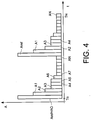
- the resulting series of measured capacitances (A) between the contacts 220 and 224 forms a time-domain output signal, shown in figure 4 .
- the output signal necessary to detect the fluid boundaries is contained entirely within the time domain.
- the capacitance A1 of the completely water immersed section is lower by design (as described above).
- the capacitance A2 of the next section is slightly lower still because it is partially immersed in fuel, which has a lower dielectric constant than water.
- the capacitances A3, A4, A5 of the next three capacitors are equal as they are all immersed in fuel.
- the capacitance A6 of the next section is slightly lower because it is only partially immersed in fuel, and the capacitance of the remaining sections A7 to AN is lower still because the dielectric constant of air is lower than that of fuel.
- the fuel and / or water level can be estimated by detecting a change in the capacitance at a specific time.
- Tw The time at which the capacitance changes from water to fuel (indicated by a drop in capacitance at A2) is denoted as Tw.
- Tf The time at which the capacitance changes from fuel to air (indicated by a drop in capacitance at A6) is denoted as Tf.
- a more accurate method of determining the height of water and / or fuel can be used in which the capacitance of the transition probe (A2 or A6) is used.
- Hwacc Hp ⁇ Tw Tp + A 2 ⁇ A 3 N A 1 ⁇ A 3
- the level H which is not as accurate as Hacc, can be used for alarms (e.g. if water exceeds a predetermined height).
- the level Hacc can be used for more accurate readings of fuel or water quantity within the tank.
- TDAC time domain analogue capacitance
- the probe 300 comprises a first plurality of stacked flat conductive sections 302, from 1 to "N" sections. Typically, N+1 is a power of 2 (e.g. 8, 16, 32, 64 etc.). Adjacent to (but not in contact with) the stacked flat sections 302 is a second plurality of stacked flat conductive sections 304. Thus, pairs of flat conductive sections are formed. The sections are mounted on the outer surface of an electrically insulating fuel tank wall 306 containing a fluid 308.
- Each section 302, 304 is identical, i.e. of equal height in the fuel fill direction, and equal width. Therefore each pair of sections can be assumed to have substantially the same capacitance properties when presented with the same dielectric substance as will be described below.
- a probe 400 comprises a common flat conductive section 402 and a plurality of stacked flat conductive sections 404 proximate thereto.
- the sections 402, 404 are mounted on the outer surface of an electrically insulating fuel tank wall 406 containing a fluid 408.
- FIG 6c a section through the plane C in figure 6b is shown.
- the electric field between the sections 402, 404 passes through the fluid 408 and as such the dielectric constant of the fluid will affect the capacitance between the common section 402 and each of the individual sections 404.
- the plates do not need to by cylindrical, and may be any shape as long as they define discrete capacitive regions.
- a multiplexer does not have to be used; a less preferable option is to continuously and simultaneously read the capacitance of each section.
- the probe may use a single, common outer plate and a plurality of inner plates. This may be advantageous if the capacitor is etched onto a carrier as it is easier to etch an outer surface of a carrier than an inner surface.
- sets of multiple opposed inner and outer plates may be used.
- N+1 is not a power of 2
- the counter is modified to count from 0 to N+1 and repeat.
- the number of counter bits is then adjusted to the next highest power of 2.
Landscapes
- Physics & Mathematics (AREA)
- Engineering & Computer Science (AREA)
- Power Engineering (AREA)
- General Physics & Mathematics (AREA)
- Chemical & Material Sciences (AREA)
- Electromagnetism (AREA)
- Thermal Sciences (AREA)
- Fluid Mechanics (AREA)
- Life Sciences & Earth Sciences (AREA)
- Health & Medical Sciences (AREA)
- Oil, Petroleum & Natural Gas (AREA)
- General Chemical & Material Sciences (AREA)
- Chemical Kinetics & Catalysis (AREA)
- Food Science & Technology (AREA)
- Medicinal Chemistry (AREA)
- Analytical Chemistry (AREA)
- Biochemistry (AREA)
- General Health & Medical Sciences (AREA)
- Immunology (AREA)
- Pathology (AREA)
- Measurement Of Levels Of Liquids Or Fluent Solid Materials (AREA)
Claims (9)
- Verfahren zum Erfassen von Grenzflächen innerhalb einer geschichteten Substanz in einem Flugzeugkraftstofftank (212), umfassend die folgenden Schritte:Bereitstellen einer kapazitiven Kraftstoffsonde (200), umfassend eine Vielzahl von diskreten kapazitiven Abschnitten (202),Eintauchen der kapazitiven Kraftstoffsonde in eine geschichtete Substanz (214, 216, 218) in einem Flugzeugkraftstofftank (212),Sequentielles Messen der Kapazität eines jeden aus der Vielzahl von diskreten kapazitiven Abschnitten (202) in vorgegebenen Zeitintervallen (t), um ein Zeitdomänenausgangssignal zu erzeugen,Erfassen einer Änderung im Zeitdomänenausgangssignal,Berechnen des Orts einer Grenzfläche entlang der Kraftstoffsonde (200) innerhalb der geschichteten Substanz auf der Grundlage der Zeit der Änderung (Tw) im Zeitdomänenausgangssignal undgekennzeichnet durch:Bereitstellen eines ersten Referenzkondensators (228) an einer bekannten Position auf der Kraftstoffsonde (200), wobei der Referenzkondensator eine Kapazität außerhalb des erwarteten Kapazitätsbereichs eines jeden Elements der geschichteten Substanz hat, undErfassen des ersten Referenzkondensators (228) durch Erfassen der Kapazität außerhalb des erwarteten Kapazitätsbereichs der geschichteten Substanz,wobei der Ort der Grenzfläche (Tw) durch Bestimmen der Zeit zwischen der Erfassung des Referenzkondensators (228) und der Erfassung der Änderung der Kapazität im Zeitdomänenausgangssignal berechnet wird.
- Verfahren zum Erfassen von Grenzflächen nach Anspruch 1, bei dem:
die Kraftstoffsonde (200) einen Multiplexer (222) umfasst, der dazu beschaffen ist, die Kapazität eines jeden aus der Vielzahl von diskreten kapazitiven Abschnitten in einem vorgegebenen Zeitintervall sequentiell zu messen, um das Zeitdomänenausgangssignal zu erzeugen. - Verfahren zum Erfassen von Grenzflächen nach Anspruch 1 oder Anspruch 2, umfassend den folgenden Schritt:
Berechnen eines genauen Orts der Grenzfläche innerhalb eines diskreten kapazitiven Abschnitts durch:Bestimmen eines Übergangsabschnitts mit einer Übergangskapazität,Berechnen des Orts der Grenzfläche innerhalb des Übergangsabschnitts durch Interpolieren der Übergangskapazität in Bezug auf die Kapazität des vorherigen diskreten kapazitiven Abschnitts und des folgenden diskreten kapazitiven Abschnitts im Zeitdomänenausgangssignal. - Kraftstoffpegelmessgerät, umfassend:eine kapazitive Kraftstoffsonde (200), die eine Kraftstofffüllrichtung definiert, wobei die kapazitive Kraftstoffsonde eine Vielzahl von diskreten kapazitiven Abschnitten (202) in der Kraftstofffüllrichtung aufweist,eine Schaltung (210), dazu beschaffen, ein Zeitdomänenausgangssignal bereitzustellen, das die Kapazität eines jeden aus der Vielzahl von diskreten kapazitiven Abschnitten der Reihe nach repräsentiert,einen Prozessor, dazu beschaffen, den Ort einer Grenzfläche innerhalb einer geschichteten Substanz, in welche die Kraftstoffsonde (200) eingetaucht wird, aus der Zeit einer Änderung im Zeitdomänenausgangssignal zu berechnen,gekennzeichnet durch:einen ersten Referenzkondensator (228) an einer ersten Position an der kapazitiven Kraftstoffsonde (200), wobei der erste Referenzkondensator (228) eine Kapazität (Aref) außerhalb des erwarteten Kapazitätsbereichs eines jeden Elements der geschichteten Substanz aufweist, undwobei der Prozessor dazu beschaffen ist, den Ort der Grenzfläche durch Bestimmen der Zeit zwischen der Erfassung des Referenzkondensators und der Erfassung der Änderung im Zeitdomänenausgangssignal zu berechnen.
- Kraftstoffpegelmessgerät nach Anspruch 4, umfassend einen Multiplexer (222), der dazu beschaffen ist, die Kapazität eines jeden aus der Vielzahl von diskreten kapazitiven Abschnitten in einem vorgegebenen Zeitintervall sequentiell zu messen, um das Zeitdomänenausgangssignal zu erzeugen.
- Kraftstoffpegelmessgerät nach Anspruch 5, bei dem der Multiplexer integral mit der Kraftstoffsonde ist.
- Kraftstoffpegelmessgerät nach einem der Ansprüche 4 bis 6, bei dem der Prozessor dazu beschaffen ist:
Berechnen eines genauen Orts der Grenzfläche innerhalb eines diskreten kapazitiven Abschnitts durch:Bestimmen eines Übergangsabschnitts mit einer Übergangskapazität,Berechnen des Orts der Grenzfläche innerhalb des Übergangsabschnitts durch Interpolieren der Übergangskapazität in Bezug auf die Kapazität des vorherigen diskreten kapazitiven Abschnitts und des folgenden diskreten kapazitiven Abschnitts im Zeitdomänenausgangssignal. - Kraftstoffpegelmessgerät nach einem der Ansprüche 4 bis 7, bei dem jeder aus der Vielzahl von diskreten kapazitiven Abschnitten (202) von gleicher Länge in Kraftstofffüllrichtung ist.
- Kraftstoffpegelmessgerät nach einem der Ansprüche 4 bis 8, bei dem jeder aus der Vielzahl von diskreten kapazitiven Abschnitten (202) ein Paar von diametral gegenüberliegenden axialen Schlitzen derart umfasst, dass jeder diskrete kapazitive Abschnitt einen ersten diskreten Unterbereich und einen zweiten diskreten Unterbereich umfasst.
Applications Claiming Priority (2)
| Application Number | Priority Date | Filing Date | Title |
|---|---|---|---|
| GBGB0909510.0A GB0909510D0 (en) | 2009-06-03 | 2009-06-03 | Fuel level measurement apparatus and method |
| PCT/GB2010/050845 WO2010139974A1 (en) | 2009-06-03 | 2010-05-24 | Aircraft fuel level measurement apparatus and method |
Publications (2)
| Publication Number | Publication Date |
|---|---|
| EP2438405A1 EP2438405A1 (de) | 2012-04-11 |
| EP2438405B1 true EP2438405B1 (de) | 2019-09-18 |
Family
ID=40902499
Family Applications (1)
| Application Number | Title | Priority Date | Filing Date |
|---|---|---|---|
| EP10722397.6A Active EP2438405B1 (de) | 2009-06-03 | 2010-05-24 | Luftfahrzeugbrennstoffsfühlstandmessungs-vorrichtung und -verfahren |
Country Status (4)
| Country | Link |
|---|---|
| US (1) | US9354099B2 (de) |
| EP (1) | EP2438405B1 (de) |
| GB (1) | GB0909510D0 (de) |
| WO (1) | WO2010139974A1 (de) |
Families Citing this family (22)
| Publication number | Priority date | Publication date | Assignee | Title |
|---|---|---|---|---|
| US8281655B2 (en) | 2009-04-03 | 2012-10-09 | Eaton Corporation | Fuel gauging system utilizing a digital fuel gauging probe |
| GB201102401D0 (en) | 2011-02-10 | 2011-03-30 | Oxford Rf Sensors Ltd | Fluid sensor |
| US9035800B2 (en) * | 2012-10-12 | 2015-05-19 | The Boeing Company | Fuel tank monitoring system |
| US9293033B2 (en) | 2013-07-16 | 2016-03-22 | The Boeing Company | Wireless fuel sensor system |
| GB2519783A (en) * | 2013-10-30 | 2015-05-06 | Airbus Operations Ltd | Capacitive liquid level sensor |
| EP3149435B1 (de) * | 2014-05-30 | 2025-04-30 | Eltek S.p.A. | Sensor zur erkennung des füllstandes eines mediums |
| EP3194909B1 (de) * | 2014-09-15 | 2024-11-13 | Eltek S.p.A. | Sensor zur erkennung des füllstandes eines mediums |
| CN107110690A (zh) * | 2014-09-15 | 2017-08-29 | 埃尔特克有限公司 | 用于检测介质的水平的传感器 |
| WO2016164881A1 (en) * | 2015-04-10 | 2016-10-13 | Covar Applied Technologies, Inc. | Discrete capacitive flow stream height measurement for partially filled pipes |
| US9153119B2 (en) * | 2015-04-23 | 2015-10-06 | Scott Stapleford | Scenting nebulizer with remote management and capacitive liquid level sensing |
| DE102015223868B4 (de) * | 2015-12-01 | 2024-02-22 | Ifm Electronic Gmbh | Anordnung und Verfahren zur kapazitiven Füllstandsbestimmung |
| DE102015016775A1 (de) * | 2015-12-23 | 2017-06-29 | Audi Ag | Verfahren zum Betreiben einer Sensoranordnung für einen Fluidtank eines Kraftfahrzeugs sowie entsprechende Sensoranordnung |
| ITUA20164407A1 (it) * | 2016-06-15 | 2017-12-15 | Eltek Spa | Sensore per la rilevazione del livello di un mezzo |
| ITUA20164400A1 (it) * | 2016-06-15 | 2017-12-15 | Eltek Spa | Sensore per la rilevazione del livello di un mezzo |
| ITUA20164395A1 (it) * | 2016-06-15 | 2017-12-15 | Eltek Spa | Sensore per la rilevazione del livello di un mezzo |
| ES2773181T3 (es) * | 2017-02-22 | 2020-07-09 | Zodiac Aerotechnics | Sonda de combustible de condensador |
| US10830469B2 (en) * | 2017-08-01 | 2020-11-10 | D-M-S Holdings, Inc. | Humidifier measurement and control |
| US20190041086A1 (en) * | 2017-08-01 | 2019-02-07 | D-M-S Holdings, Inc. | Humidifier liquid tank |
| US10760937B2 (en) * | 2017-09-08 | 2020-09-01 | RV Whisper LLC | System and method for measuring the level of fluid in a container |
| FR3071054B1 (fr) * | 2017-09-13 | 2021-01-29 | Intersens | Sonde pour dispositif limiteur de remplissage pour citerne de transport de carburant petrolier liquide et dispositif limiteur de remplissage correspondant |
| EP3457096B1 (de) * | 2017-09-13 | 2021-07-07 | Intersens | Verbesserte sonde für füllbegrenzungsvorrichtung für transportzisterne für kraftstoff auf erdölbasis, und entsprechende füllbegrenzungsvorrichtung |
| CN113144339B (zh) * | 2021-04-13 | 2023-08-01 | 山东亚华电子股份有限公司 | 一种输液监测装置 |
Family Cites Families (17)
| Publication number | Priority date | Publication date | Assignee | Title |
|---|---|---|---|---|
| NO742093L (de) * | 1974-06-10 | 1975-12-11 | Navaltronic As | |
| US4099167A (en) | 1977-02-10 | 1978-07-04 | P.R. Mallory & Co. Inc. | Capacitive means for measuring the level of a liquid |
| JPS60192227A (ja) | 1984-03-14 | 1985-09-30 | Tokyo Tatsuno Co Ltd | 静電容量式液面計用電極 |
| US4601201A (en) | 1984-03-14 | 1986-07-22 | Tokyo Tatsuno Co., Ltd. | Liquid level and quantity measuring apparatus |
| US5103368A (en) * | 1990-05-07 | 1992-04-07 | Therm-O-Disc, Incorporated | Capacitive fluid level sensor |
| US5613399A (en) * | 1993-10-27 | 1997-03-25 | Kdi Precision Products, Inc. | Method for liquid level detection |
| US5406843A (en) | 1993-10-27 | 1995-04-18 | Kdi Corporation, Inc. | Digital liquid level sensing apparatus |
| US6101873A (en) * | 1996-05-17 | 2000-08-15 | Nohken Inc. | Level sensor |
| DE19630075A1 (de) | 1996-07-26 | 1998-05-28 | Gerhard Dipl Ing Wergen | Mehrdimensional wirkende Handhabe |
| DE19713267A1 (de) | 1997-01-28 | 1998-07-30 | Abb Research Ltd | Verfahren zur Bestimmung der Dielektrizitätskonstante und/oder der Leitfähigkeit mindestens eines Mediums sowie Vorrichtung zur Durchführung des Verfahrens |
| EP0995083B1 (de) | 1997-01-28 | 2002-02-20 | Abb Research Ltd. | Kapazitiver füllstandssensor mit optimierter elektrodengeometrie |
| JPH11311562A (ja) | 1998-04-27 | 1999-11-09 | Wako:Kk | 水位センサ |
| DE10008093B4 (de) * | 2000-02-22 | 2007-07-05 | Ifm Electronic Gmbh | Kapazitives Füllstandsmessgerät |
| US6568264B2 (en) * | 2001-02-23 | 2003-05-27 | Charles E. Heger | Wireless swimming pool water level system |
| DE10345707A1 (de) * | 2003-10-01 | 2005-04-21 | Volkswagen Ag | Verfahren zur Füllstanderfassung in einem Behälter und entsprechendes Füllstand-Messsystem |
| US8181516B2 (en) * | 2006-10-26 | 2012-05-22 | Inergy Automotive Systems Research (Societe Anonyme) | Measuring a liquid level in a tank with two measurement capacitors and two reference capacitors |
| EP2034282A1 (de) | 2007-07-19 | 2009-03-11 | Siemens Milltronics Process Instruments Inc. | Verfahren und Vorrichtung zum Messen von Medienschichten und Schnittstellen dazwischen mithilfe einer Multisensorsonde |
-
2009
- 2009-06-03 GB GBGB0909510.0A patent/GB0909510D0/en not_active Ceased
-
2010
- 2010-05-24 WO PCT/GB2010/050845 patent/WO2010139974A1/en not_active Ceased
- 2010-05-24 US US13/319,166 patent/US9354099B2/en active Active
- 2010-05-24 EP EP10722397.6A patent/EP2438405B1/de active Active
Non-Patent Citations (1)
| Title |
|---|
| None * |
Also Published As
| Publication number | Publication date |
|---|---|
| WO2010139974A1 (en) | 2010-12-09 |
| EP2438405A1 (de) | 2012-04-11 |
| GB0909510D0 (en) | 2009-07-15 |
| US20120065904A1 (en) | 2012-03-15 |
| US9354099B2 (en) | 2016-05-31 |
Similar Documents
| Publication | Publication Date | Title |
|---|---|---|
| US9354099B2 (en) | Aircraft fuel level measurement apparatus and method | |
| US20130276533A1 (en) | Device for measuring fluid level in a container | |
| US20150033830A1 (en) | Automated phase separation and fuel quality sensor | |
| US20130298667A1 (en) | Apparatus and Method for Capacitive Fill Level Measurement | |
| US10371555B2 (en) | Capacitive continuous fluid level sensor | |
| CA2176860C (en) | A method for measuring a fluid level and an apparatus thereof | |
| CN103376144A (zh) | 液位检测装置 | |
| US20120291541A1 (en) | Digital field-induction water-level intelligent sensing system and its implementation method | |
| US12326354B2 (en) | Capacitive filling level probe without dead zone | |
| EP1212607B1 (de) | Verfahren zur messung des wassergehaltes | |
| KR20210154139A (ko) | 이중 극성 상호 용량 액체 감지 | |
| US20070252715A1 (en) | Liquid quality and level sensor | |
| JP2013190379A (ja) | 液面レベル検出装置 | |
| US10114139B1 (en) | Multi-capacitor liquid detection device and method(s) of use | |
| JP6132482B2 (ja) | 液位検出装置 | |
| KR101831963B1 (ko) | 복수 개의 pcb 패드를 이용한 탱크 내부 유체의 수위감지장치 | |
| US12442676B2 (en) | Differentiating between fuel and water using capacitive measurement thereof | |
| CN116642556A (zh) | 一种基于两次测量法的容器液量非接触测量传感器 | |
| EP3130896B1 (de) | Flüssigkeitsstandsensor mit isolierendem bereich über dem sondenfuss | |
| JP5692020B2 (ja) | 液位検出装置 | |
| CN111206376A (zh) | 液位检测装置及方法、洗衣机 | |
| CN117630088A (zh) | 液体加热容器及其基于差值判别的液体加热状态监测装置 | |
| CN116642557A (zh) | 一种基于三次测量法的容器液量非接触测量传感器 | |
| WO2022216601A1 (en) | Differentiating between fuel and water using capacitive measurement thereof | |
| HK1170564A (en) | Device for measuring fluid level in a container |
Legal Events
| Date | Code | Title | Description |
|---|---|---|---|
| PUAI | Public reference made under article 153(3) epc to a published international application that has entered the european phase |
Free format text: ORIGINAL CODE: 0009012 |
|
| 17P | Request for examination filed |
Effective date: 20111201 |
|
| AK | Designated contracting states |
Kind code of ref document: A1 Designated state(s): AL AT BE BG CH CY CZ DE DK EE ES FI FR GB GR HR HU IE IS IT LI LT LU LV MC MK MT NL NO PL PT RO SE SI SK SM TR |
|
| DAX | Request for extension of the european patent (deleted) | ||
| 17Q | First examination report despatched |
Effective date: 20161006 |
|
| STAA | Information on the status of an ep patent application or granted ep patent |
Free format text: STATUS: EXAMINATION IS IN PROGRESS |
|
| RIC1 | Information provided on ipc code assigned before grant |
Ipc: G01F 23/26 20060101AFI20190130BHEP Ipc: G01N 33/28 20060101ALI20190130BHEP |
|
| GRAP | Despatch of communication of intention to grant a patent |
Free format text: ORIGINAL CODE: EPIDOSNIGR1 |
|
| STAA | Information on the status of an ep patent application or granted ep patent |
Free format text: STATUS: GRANT OF PATENT IS INTENDED |
|
| INTG | Intention to grant announced |
Effective date: 20190409 |
|
| GRAS | Grant fee paid |
Free format text: ORIGINAL CODE: EPIDOSNIGR3 |
|
| GRAA | (expected) grant |
Free format text: ORIGINAL CODE: 0009210 |
|
| STAA | Information on the status of an ep patent application or granted ep patent |
Free format text: STATUS: THE PATENT HAS BEEN GRANTED |
|
| AK | Designated contracting states |
Kind code of ref document: B1 Designated state(s): AL AT BE BG CH CY CZ DE DK EE ES FI FR GB GR HR HU IE IS IT LI LT LU LV MC MK MT NL NO PL PT RO SE SI SK SM TR |
|
| REG | Reference to a national code |
Ref country code: GB Ref legal event code: FG4D |
|
| REG | Reference to a national code |
Ref country code: CH Ref legal event code: EP |
|
| REG | Reference to a national code |
Ref country code: DE Ref legal event code: R096 Ref document number: 602010061097 Country of ref document: DE |
|
| REG | Reference to a national code |
Ref country code: AT Ref legal event code: REF Ref document number: 1181884 Country of ref document: AT Kind code of ref document: T Effective date: 20191015 |
|
| REG | Reference to a national code |
Ref country code: IE Ref legal event code: FG4D |
|
| REG | Reference to a national code |
Ref country code: NL Ref legal event code: MP Effective date: 20190918 |
|
| PG25 | Lapsed in a contracting state [announced via postgrant information from national office to epo] |
Ref country code: HR Free format text: LAPSE BECAUSE OF FAILURE TO SUBMIT A TRANSLATION OF THE DESCRIPTION OR TO PAY THE FEE WITHIN THE PRESCRIBED TIME-LIMIT Effective date: 20190918 Ref country code: BG Free format text: LAPSE BECAUSE OF FAILURE TO SUBMIT A TRANSLATION OF THE DESCRIPTION OR TO PAY THE FEE WITHIN THE PRESCRIBED TIME-LIMIT Effective date: 20191218 Ref country code: SE Free format text: LAPSE BECAUSE OF FAILURE TO SUBMIT A TRANSLATION OF THE DESCRIPTION OR TO PAY THE FEE WITHIN THE PRESCRIBED TIME-LIMIT Effective date: 20190918 Ref country code: LT Free format text: LAPSE BECAUSE OF FAILURE TO SUBMIT A TRANSLATION OF THE DESCRIPTION OR TO PAY THE FEE WITHIN THE PRESCRIBED TIME-LIMIT Effective date: 20190918 Ref country code: FI Free format text: LAPSE BECAUSE OF FAILURE TO SUBMIT A TRANSLATION OF THE DESCRIPTION OR TO PAY THE FEE WITHIN THE PRESCRIBED TIME-LIMIT Effective date: 20190918 Ref country code: NO Free format text: LAPSE BECAUSE OF FAILURE TO SUBMIT A TRANSLATION OF THE DESCRIPTION OR TO PAY THE FEE WITHIN THE PRESCRIBED TIME-LIMIT Effective date: 20191218 |
|
| REG | Reference to a national code |
Ref country code: LT Ref legal event code: MG4D |
|
| PG25 | Lapsed in a contracting state [announced via postgrant information from national office to epo] |
Ref country code: GR Free format text: LAPSE BECAUSE OF FAILURE TO SUBMIT A TRANSLATION OF THE DESCRIPTION OR TO PAY THE FEE WITHIN THE PRESCRIBED TIME-LIMIT Effective date: 20191219 Ref country code: LV Free format text: LAPSE BECAUSE OF FAILURE TO SUBMIT A TRANSLATION OF THE DESCRIPTION OR TO PAY THE FEE WITHIN THE PRESCRIBED TIME-LIMIT Effective date: 20190918 Ref country code: AL Free format text: LAPSE BECAUSE OF FAILURE TO SUBMIT A TRANSLATION OF THE DESCRIPTION OR TO PAY THE FEE WITHIN THE PRESCRIBED TIME-LIMIT Effective date: 20190918 |
|
| REG | Reference to a national code |
Ref country code: AT Ref legal event code: MK05 Ref document number: 1181884 Country of ref document: AT Kind code of ref document: T Effective date: 20190918 |
|
| PG25 | Lapsed in a contracting state [announced via postgrant information from national office to epo] |
Ref country code: NL Free format text: LAPSE BECAUSE OF FAILURE TO SUBMIT A TRANSLATION OF THE DESCRIPTION OR TO PAY THE FEE WITHIN THE PRESCRIBED TIME-LIMIT Effective date: 20190918 Ref country code: PT Free format text: LAPSE BECAUSE OF FAILURE TO SUBMIT A TRANSLATION OF THE DESCRIPTION OR TO PAY THE FEE WITHIN THE PRESCRIBED TIME-LIMIT Effective date: 20200120 Ref country code: ES Free format text: LAPSE BECAUSE OF FAILURE TO SUBMIT A TRANSLATION OF THE DESCRIPTION OR TO PAY THE FEE WITHIN THE PRESCRIBED TIME-LIMIT Effective date: 20190918 Ref country code: EE Free format text: LAPSE BECAUSE OF FAILURE TO SUBMIT A TRANSLATION OF THE DESCRIPTION OR TO PAY THE FEE WITHIN THE PRESCRIBED TIME-LIMIT Effective date: 20190918 Ref country code: AT Free format text: LAPSE BECAUSE OF FAILURE TO SUBMIT A TRANSLATION OF THE DESCRIPTION OR TO PAY THE FEE WITHIN THE PRESCRIBED TIME-LIMIT Effective date: 20190918 Ref country code: RO Free format text: LAPSE BECAUSE OF FAILURE TO SUBMIT A TRANSLATION OF THE DESCRIPTION OR TO PAY THE FEE WITHIN THE PRESCRIBED TIME-LIMIT Effective date: 20190918 Ref country code: IT Free format text: LAPSE BECAUSE OF FAILURE TO SUBMIT A TRANSLATION OF THE DESCRIPTION OR TO PAY THE FEE WITHIN THE PRESCRIBED TIME-LIMIT Effective date: 20190918 Ref country code: PL Free format text: LAPSE BECAUSE OF FAILURE TO SUBMIT A TRANSLATION OF THE DESCRIPTION OR TO PAY THE FEE WITHIN THE PRESCRIBED TIME-LIMIT Effective date: 20190918 |
|
| PG25 | Lapsed in a contracting state [announced via postgrant information from national office to epo] |
Ref country code: SM Free format text: LAPSE BECAUSE OF FAILURE TO SUBMIT A TRANSLATION OF THE DESCRIPTION OR TO PAY THE FEE WITHIN THE PRESCRIBED TIME-LIMIT Effective date: 20190918 Ref country code: IS Free format text: LAPSE BECAUSE OF FAILURE TO SUBMIT A TRANSLATION OF THE DESCRIPTION OR TO PAY THE FEE WITHIN THE PRESCRIBED TIME-LIMIT Effective date: 20200224 Ref country code: SK Free format text: LAPSE BECAUSE OF FAILURE TO SUBMIT A TRANSLATION OF THE DESCRIPTION OR TO PAY THE FEE WITHIN THE PRESCRIBED TIME-LIMIT Effective date: 20190918 Ref country code: CZ Free format text: LAPSE BECAUSE OF FAILURE TO SUBMIT A TRANSLATION OF THE DESCRIPTION OR TO PAY THE FEE WITHIN THE PRESCRIBED TIME-LIMIT Effective date: 20190918 |
|
| REG | Reference to a national code |
Ref country code: DE Ref legal event code: R097 Ref document number: 602010061097 Country of ref document: DE |
|
| PLBE | No opposition filed within time limit |
Free format text: ORIGINAL CODE: 0009261 |
|
| STAA | Information on the status of an ep patent application or granted ep patent |
Free format text: STATUS: NO OPPOSITION FILED WITHIN TIME LIMIT |
|
| PG2D | Information on lapse in contracting state deleted |
Ref country code: IS |
|
| PG25 | Lapsed in a contracting state [announced via postgrant information from national office to epo] |
Ref country code: DK Free format text: LAPSE BECAUSE OF FAILURE TO SUBMIT A TRANSLATION OF THE DESCRIPTION OR TO PAY THE FEE WITHIN THE PRESCRIBED TIME-LIMIT Effective date: 20190918 Ref country code: IS Free format text: LAPSE BECAUSE OF FAILURE TO SUBMIT A TRANSLATION OF THE DESCRIPTION OR TO PAY THE FEE WITHIN THE PRESCRIBED TIME-LIMIT Effective date: 20200119 |
|
| 26N | No opposition filed |
Effective date: 20200619 |
|
| PG25 | Lapsed in a contracting state [announced via postgrant information from national office to epo] |
Ref country code: SI Free format text: LAPSE BECAUSE OF FAILURE TO SUBMIT A TRANSLATION OF THE DESCRIPTION OR TO PAY THE FEE WITHIN THE PRESCRIBED TIME-LIMIT Effective date: 20190918 |
|
| PG25 | Lapsed in a contracting state [announced via postgrant information from national office to epo] |
Ref country code: MC Free format text: LAPSE BECAUSE OF FAILURE TO SUBMIT A TRANSLATION OF THE DESCRIPTION OR TO PAY THE FEE WITHIN THE PRESCRIBED TIME-LIMIT Effective date: 20190918 Ref country code: LI Free format text: LAPSE BECAUSE OF NON-PAYMENT OF DUE FEES Effective date: 20200531 Ref country code: CH Free format text: LAPSE BECAUSE OF NON-PAYMENT OF DUE FEES Effective date: 20200531 |
|
| REG | Reference to a national code |
Ref country code: BE Ref legal event code: MM Effective date: 20200531 |
|
| PG25 | Lapsed in a contracting state [announced via postgrant information from national office to epo] |
Ref country code: LU Free format text: LAPSE BECAUSE OF NON-PAYMENT OF DUE FEES Effective date: 20200524 |
|
| PG25 | Lapsed in a contracting state [announced via postgrant information from national office to epo] |
Ref country code: IE Free format text: LAPSE BECAUSE OF NON-PAYMENT OF DUE FEES Effective date: 20200524 |
|
| PG25 | Lapsed in a contracting state [announced via postgrant information from national office to epo] |
Ref country code: BE Free format text: LAPSE BECAUSE OF NON-PAYMENT OF DUE FEES Effective date: 20200531 |
|
| PG25 | Lapsed in a contracting state [announced via postgrant information from national office to epo] |
Ref country code: TR Free format text: LAPSE BECAUSE OF FAILURE TO SUBMIT A TRANSLATION OF THE DESCRIPTION OR TO PAY THE FEE WITHIN THE PRESCRIBED TIME-LIMIT Effective date: 20190918 Ref country code: MT Free format text: LAPSE BECAUSE OF FAILURE TO SUBMIT A TRANSLATION OF THE DESCRIPTION OR TO PAY THE FEE WITHIN THE PRESCRIBED TIME-LIMIT Effective date: 20190918 Ref country code: CY Free format text: LAPSE BECAUSE OF FAILURE TO SUBMIT A TRANSLATION OF THE DESCRIPTION OR TO PAY THE FEE WITHIN THE PRESCRIBED TIME-LIMIT Effective date: 20190918 |
|
| PG25 | Lapsed in a contracting state [announced via postgrant information from national office to epo] |
Ref country code: MK Free format text: LAPSE BECAUSE OF FAILURE TO SUBMIT A TRANSLATION OF THE DESCRIPTION OR TO PAY THE FEE WITHIN THE PRESCRIBED TIME-LIMIT Effective date: 20190918 |
|
| PGFP | Annual fee paid to national office [announced via postgrant information from national office to epo] |
Ref country code: DE Payment date: 20250521 Year of fee payment: 16 |
|
| PGFP | Annual fee paid to national office [announced via postgrant information from national office to epo] |
Ref country code: GB Payment date: 20250526 Year of fee payment: 16 |
|
| PGFP | Annual fee paid to national office [announced via postgrant information from national office to epo] |
Ref country code: FR Payment date: 20250528 Year of fee payment: 16 |