EP2437506A2 - 3D-Bildanzeigevorrichtung - Google Patents
3D-Bildanzeigevorrichtung Download PDFInfo
- Publication number
- EP2437506A2 EP2437506A2 EP11180011A EP11180011A EP2437506A2 EP 2437506 A2 EP2437506 A2 EP 2437506A2 EP 11180011 A EP11180011 A EP 11180011A EP 11180011 A EP11180011 A EP 11180011A EP 2437506 A2 EP2437506 A2 EP 2437506A2
- Authority
- EP
- European Patent Office
- Prior art keywords
- retardation
- glasses
- polarizing plate
- display
- plate
- Prior art date
- Legal status (The legal status is an assumption and is not a legal conclusion. Google has not performed a legal analysis and makes no representation as to the accuracy of the status listed.)
- Withdrawn
Links
Images


Classifications
-
- G—PHYSICS
- G02—OPTICS
- G02B—OPTICAL ELEMENTS, SYSTEMS OR APPARATUS
- G02B30/00—Optical systems or apparatus for producing three-dimensional [3D] effects, e.g. stereoscopic images
- G02B30/20—Optical systems or apparatus for producing three-dimensional [3D] effects, e.g. stereoscopic images by providing first and second parallax images to an observer's left and right eyes
- G02B30/22—Optical systems or apparatus for producing three-dimensional [3D] effects, e.g. stereoscopic images by providing first and second parallax images to an observer's left and right eyes of the stereoscopic type
- G02B30/25—Optical systems or apparatus for producing three-dimensional [3D] effects, e.g. stereoscopic images by providing first and second parallax images to an observer's left and right eyes of the stereoscopic type using polarisation techniques
-
- H—ELECTRICITY
- H04—ELECTRIC COMMUNICATION TECHNIQUE
- H04N—PICTORIAL COMMUNICATION, e.g. TELEVISION
- H04N13/00—Stereoscopic video systems; Multi-view video systems; Details thereof
- H04N13/30—Image reproducers
- H04N13/332—Displays for viewing with the aid of special glasses or head-mounted displays [HMD]
- H04N13/337—Displays for viewing with the aid of special glasses or head-mounted displays [HMD] using polarisation multiplexing
-
- G—PHYSICS
- G02—OPTICS
- G02B—OPTICAL ELEMENTS, SYSTEMS OR APPARATUS
- G02B30/00—Optical systems or apparatus for producing three-dimensional [3D] effects, e.g. stereoscopic images
-
- G—PHYSICS
- G02—OPTICS
- G02B—OPTICAL ELEMENTS, SYSTEMS OR APPARATUS
- G02B30/00—Optical systems or apparatus for producing three-dimensional [3D] effects, e.g. stereoscopic images
- G02B30/20—Optical systems or apparatus for producing three-dimensional [3D] effects, e.g. stereoscopic images by providing first and second parallax images to an observer's left and right eyes
- G02B30/22—Optical systems or apparatus for producing three-dimensional [3D] effects, e.g. stereoscopic images by providing first and second parallax images to an observer's left and right eyes of the stereoscopic type
- G02B30/24—Optical systems or apparatus for producing three-dimensional [3D] effects, e.g. stereoscopic images by providing first and second parallax images to an observer's left and right eyes of the stereoscopic type involving temporal multiplexing, e.g. using sequentially activated left and right shutters
-
- G—PHYSICS
- G02—OPTICS
- G02F—OPTICAL DEVICES OR ARRANGEMENTS FOR THE CONTROL OF LIGHT BY MODIFICATION OF THE OPTICAL PROPERTIES OF THE MEDIA OF THE ELEMENTS INVOLVED THEREIN; NON-LINEAR OPTICS; FREQUENCY-CHANGING OF LIGHT; OPTICAL LOGIC ELEMENTS; OPTICAL ANALOGUE/DIGITAL CONVERTERS
- G02F1/00—Devices or arrangements for the control of the intensity, colour, phase, polarisation or direction of light arriving from an independent light source, e.g. switching, gating or modulating; Non-linear optics
- G02F1/01—Devices or arrangements for the control of the intensity, colour, phase, polarisation or direction of light arriving from an independent light source, e.g. switching, gating or modulating; Non-linear optics for the control of the intensity, phase, polarisation or colour
- G02F1/13—Devices or arrangements for the control of the intensity, colour, phase, polarisation or direction of light arriving from an independent light source, e.g. switching, gating or modulating; Non-linear optics for the control of the intensity, phase, polarisation or colour based on liquid crystals, e.g. single liquid crystal display cells
-
- H—ELECTRICITY
- H04—ELECTRIC COMMUNICATION TECHNIQUE
- H04N—PICTORIAL COMMUNICATION, e.g. TELEVISION
- H04N13/00—Stereoscopic video systems; Multi-view video systems; Details thereof
-
- H—ELECTRICITY
- H04—ELECTRIC COMMUNICATION TECHNIQUE
- H04N—PICTORIAL COMMUNICATION, e.g. TELEVISION
- H04N13/00—Stereoscopic video systems; Multi-view video systems; Details thereof
- H04N13/30—Image reproducers
- H04N13/332—Displays for viewing with the aid of special glasses or head-mounted displays [HMD]
- H04N13/341—Displays for viewing with the aid of special glasses or head-mounted displays [HMD] using temporal multiplexing
-
- H—ELECTRICITY
- H04—ELECTRIC COMMUNICATION TECHNIQUE
- H04N—PICTORIAL COMMUNICATION, e.g. TELEVISION
- H04N2213/00—Details of stereoscopic systems
- H04N2213/008—Aspects relating to glasses for viewing stereoscopic images
Definitions
- the present disclosure relates to a 3D image display device performing 3D display by using shutter glasses.
- a glasses-type 3D image display device has been known in related art, which realizes 3D vision by allowing an observer to see different images having parallax with both eyes by wearing special glasses for 3D vision using liquid crystal shutters (refer to JP-A-08-327961 (Patent Document 1), JP-A-2002-82307 (Patent Document 2)).
- Patent Document 1 JP-A-08-327961
- Patent Document 2 JP-A-2002-82307
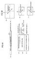
- Fig. 17 shows a common glasses-type structure example of a 3D image display device in related art.
- the 3D display device includes a display device 101 displaying images and liquid crystal shutter-type shutter glasses 102 for observing the display device 101.
- the display device 101 includes a display unit 111 having a two-dimensional display panel such as a liquid crystal display device or a CRT (cathode ray tube) and a display-side polarizing plate 112 provided on the side of a display surface 111A of the display unit 111.
- the shutter glasses 102 include a left-eye shutter 102L arranged on the side of a left-eye 3L of the observer and a right-eye shutter 102R arranged on the side of a right-eye 3R of the observer.
- the left-eye shutter 102L includes, for example, a TN (Twisted Nematic) type liquid crystal cell 120, a first glasses-side polarizing plate 121 arranged at the liquid crystal cell 120 on the observer's side and a second glasses-side polarizing plate 122 arranged at the liquid crystal cell 120 on the side of the display unit 111.
- the right-eye shutter 102R has the same structure as the left-eye shutter 102L.
- left-eye images and right-eye images are alternately displayed on the display device 101 in a time-sharing manner.
- the left-eye shutter 102L and the right-eye shutter 102R in the shutter glasses 102 are on/off (open/close) controlled alternately in synchronization with the display timing, thereby allowing the observer to recognize only left-eye images on the side of the left-eye 3L and to recognize only right-eye images on the side of the right-eye 3R to realize 3D vision.
- the glasses-type 3D image display device not only light of video from the display device 101 but also light of external lighting are incident according to audio/visual environment in the shutter glasses 102.
- a blinking frequency of external lighting and an opening and closing frequency of the shutter glasses 102 are interfered with each other in a specific relation and flickers occur. This is extremely uncomfortable for the observer and will cause visual fatigue.
- a circularly polarizing plate (1/4 wavelength plate) disclosed in, for example, Patent Document 2 can be used. That is, as shown in Fig. 19 , a 1/4 wavelength plate 113 is arranged on a surface of the display-side polarizing plate 112 in the display device 101 as well as a 1/4 wavelength plate 123 is arranged at the liquid crystal cell 120 on the side of the display unit 111 in shutter glasses 102B.
- the relations between polarization axes and retardation axes in respective units are, for example, shown as Fig. 20 .
- a polarization axis 141 of the display-side polarizing plate 112 and a polarization axis 144 of the first glasses-side polarizing plate 121 are orthogonal to each other (absorption axes of them or transmission axes of them are orthogonal to each other).
- a retardation axis 142 of the display-side 1/4 wavelength plate 113 is inclined 45 degrees with respect to the polarization axis 141 of the display-side polarizing plate 112, and the retardation axis 142 of the display-side 1/4 wavelength plate 113 and a retardation axis 143 of the glasses-side 1/4 wavelength plate 123 are orthogonal to each other (slow axes of them and fast axes of the them are orthogonal to each other).
- a direction of the polarization axis 141 of the display-side polarizing plate 112 is 90 degrees
- a direction of the polarization axis 144 of the first glasses-side polarizing plate 121 is 0 (zero) degree
- a direction of the retardation axis 142 of the display-side 1/4 wavelength plate 113 is 135 degrees
- a direction of the retardation axis 143 of the glasses-side 1/4 wavelength plate 123 are 45 degrees.
- linear polarization light emitted from the display-side polarizing plate 112 becomes circularly polarized light by the display-side 1/4 wavelength plate 113 and returns to linear polarization light again by the glasses-side 1/4 wavelength plate 123 to be incident on the liquid crystal cells 120, thereby allowing the shutter glasses 102B to function as shutters with respect to video light from the display device 101.
- the 1/4 wavelength plate 113 it is necessary to arrange the 1/4 wavelength plate 113 on the side of the display device 101, therefore, a wavelength plate having a large area is necessary, which leads to cost increase.
- An embodiment of the present disclosure is directed to a 3D image display device including a display unit displaying left-eye images and right-eye images alternately in a time-sharing manner, a display-side polarizing plate arranged on the side of a display surface of the display unit, and shutter glasses having a left-eye shutter and a right-eye shutter, opening and closing the left-eye shutter and the right-eye shutter in accordance with display states of images displayed on the display unit.
- Each of the left-eye shutter and the right-eye shutter has a liquid crystal cell, a retardation plate arranged at the liquid crystal cell on the side of the display unit, and a first glasses-side polarizing plate arranged at the liquid crystal cell on the opposite side of the side where the retardation plate is provided, and a polarization axis of the display-side polarizing plate and a polarization axis of the first glasses-side polarizing plate are orthogonal to each other as well as the polarization axis of the display-side polarizing plate and a retardation axis of the retardation plate are parallel or orthogonal to each other.
- the polarization axis of the display-side polarizing plate and the polarization axis of the first glasses-side polarizing plate are orthogonal to each other as well as the polarization axis of the display-side polarizing plate and the retardation axis of the retardation plate are parallel or orthogonal to each other, therefore, operations by the retardation plate are generated only when the shutter glasses are inclined with respect to the display surface and optical compensation is made so that color variation is suppressed.
- the display-side polarizing plate is arranged on the side of the display surface of the display unit as well as the retardation plates are arranged on the side of the shutter glasses, and the polarization axis of the display-side polarizing plate and the retardation axes of the retardation plates are arranged to be parallel or orthogonal to each other, therefore, operations by the retardation plates are generated only when the shutter glasses are inclined with respect to the display surface. Accordingly, the color variation occurring when the shutter glasses are inclined with respect to the display surface can be suppressed while maintaining normal display characteristics in a state where the shutter glasses are not inclined with respect to the display surface. Additionally, the shutter glasses are provided with the retardation plates, therefore, the retardation plates occupy a small area as compared with a case where the plates are provided in the display unit, which simplifies the structure and reduces costs.
- Fig. 1 shows an entire structure example of a 3D image display device according to a first embodiment of the present disclosure.
- the 3D image display device includes a display device 1 displaying images and liquid crystal shutter-type shutter glasses 2 for observing the display device 1.
- the display device 1 includes a display unit 11 having a two-dimensional display panel such as a liquid crystal display device or a CRT (cathode ray tube) and a display-side polarizing plate 12 provided on the side of a display surface 11A of the display unit 11.
- a polarizing plate is normally provided on the emission side. Therefore, in the case of the liquid crystal display device, the polarizing plate provided in the liquid crystal display device itself can be used as the display-side polarizing plate 12.
- the shutter glasses 2 include a left-eye shutter 2L arranged on the side of a left-eye 3L of the observer and a right-eye shutter 2R arranged on the side of a right-eye 3R of the observer.
- the left-eye shutter 2L includes, for example, a TN (Twisted Nematic) type or a STN (Super Twisted Nematic) type liquid crystal cell 20, a retardation plate 22 arranged at the liquid crystal cell 20 on the side of the display unit 11 and a glasses-side polarizing plate 21 arranged at the liquid crystal cell 20 on the opposite side (observer's side) of the side where the retardation plate 22 is provided.
- the right-eye shutter 2R has the same structure as the left-eye shutter 2L.
- left-eye images and right-eye images are alternately displayed on the display unit 11 of the display device 1 in a time-sharing manner.
- the left-eye shutter 2L and the right-eye shutter 2R are on/off (open/close) controlled alternately in the shutter glasses 2 in accordance with a display state of images displayed on the display unit 11, namely, in synchronization with the timing at which the left-eye images and right-eye images are alternately displayed. Accordingly, the observer is allowed to recognize only left-eye images on the side of the left-eye 3L and to recognize only right-eye images on the side of the right-eye 3R to realize 3D vision.
- the liquid crystal cells 20 of the shutter glasses 2 have a function of generating retardation in incident light and rotating the polarization state due to refractive index anisotropy included in liquid crystal molecules.
- a liquid crystal layer works so that the polarization state of linear polarization light emitted through the display-side polarizing plate 12 ideally rotates approximately 90 degrees in the polarization direction when the shutters are on (in an open state), however, phase shift of light generated by the liquid crystal layer is deviated from the optimum value when inclining the head. Moreover, the deviation differs when inclining the head to the right and to the left.
- the retardation plate 22 is arranged as shown in, for example, Fig.
- the optimum retardation value of the retardation plate 22 appears periodically as described later, however, the retardation value is desirable to be equal to or less than 600nm, as it is difficult to make a retardation film exceeding 600nm, in which retardation values are not stable.
- Fig. 2 and Fig. 3 show relations between polarization axes and retardation axes in respective units of the 3D image display device shown in Fig. 1 .
- a polarization axis 41 of the display-side polarizing plate 12 and a polarization axis 43 of the glasses-side polarizing plate 21 are orthogonal to each other (absorption axes of them or transmission axes of them are orthogonal to each other).
- the polarization axis 41 of the display-side polarizing plate 12 and a retardation axis 42 of the retardation plate 22 are parallel to each other (for example, the absorption axis of the display-side polarizing plate 12 and the slow axis of the retardation plate 22 are parallel to each other).
- a direction of the polarization axis 41 of the display-side polarizing plate 12 is 90 degrees
- a direction of the polarization axis 43 of the glasses-side polarizing plate 21 is 0 (zero) degree
- a direction of the retardation axis 42 of the retardation plate 22 is 90 degree.
- relative relations in the axial direction between the polarization axes and the retardation axis in respective units are the same as Fig. 2 , that is, the axis angle is not limited to 0 degree and 90 degrees.
- the polarization axis 41 of the display-side polarizing plate 12 and the polarization axis 43 of the glasses-side polarizing plate 21 are orthogonal to each other in the same manner as the first combination example of Fig. 2 (absorption axes of them or transmission axes of them are orthogonal to each other) .
- the polarization axis 41 of the display-side polarizing plate 12 and the retardation axis 42 of the retardation plate 22 are orthogonal to each other (for example, the absorption axis of the display-side polarizing plate 12 and the slow axis of the retardation plate 22 are orthogonal to each other).
- a direction of the polarization axis 41 of the display-side polarizing plate 12 is 90 degrees
- a direction of the polarization axis 43 of the glasses-side polarizing plate 21 is 0 (zero) degree
- a direction of the retardation axis 42 of the retardation plate 22 is 0 (zero) degree. It is preferable that relative relations in the axial direction between the polarization axes and the retardation axis in respective units are the same as Fig. 3 , that is, the axis angle is not limited to 0 degree and 90 degrees.
- Figs. 4A and 4B show a first specific structure example.
- the relative relations of respective units in the axial direction correspond to Fig. 2 .
- the direction of the polarization axis 41 of the display-side polarizing plate 12 is 135 degrees
- the direction of the polarization axis 43 of the glasses-side polarizing plate 21 is 45 degrees
- the direction of the retardation axis 42 of the retardation plate 22 is 135 degrees
- a material of the retardation plate 22 is cycloolefin polymer.
- the liquid crystal cell 20 is the TN type and the difference ( ⁇ n) between a refractive index (ne) of liquid crystal molecules in a long-axis direction and a refractive index (no) in a short-axis direction is 0.136, and a cell gap is 3.4 ⁇ m.
- An alignment direction on a (top) side (side where the retardation plate 22 is arranged) of the liquid crystal cell 20 is 135 degrees and an alignment direction on a (bottom) side (side where the glasses-side polarizing plate 21 is arranged) is 45 degrees. That is, the direction of the retardation axis 42 of the retardation plate 22 and the alignment direction on the (top) side of the liquid crystal cell 20 are parallel.
- Figs. 5A and 5B show a second specific structure example.
- the relative relations of respective units in the axial direction correspond to Fig. 3 .
- the direction of the polarization axis 41 of the display-side polarizing plate 12 is 45 degrees
- the direction of the polarization axis 43 of the glasses-side polarizing plate 21 is 135 degrees
- the direction of the retardation axis 42 of the retardation plate 22 is 135 degrees.
- a material of the retardation plate 22 is cycloolefin polymer.
- the liquid crystal cell 20 is the TN type and the difference ( ⁇ n) between the refractive index (ne) of liquid crystal molecules in the long-axis direction and the refractive index (no) in the short-axis direction is 0.136, and the cell gap is 3.4 ⁇ m.
- the alignment direction on the (top) side (side where the retardation plate 22 is arranged) of the liquid crystal cell 20 is 135 degrees and the alignment direction on the (bottom) side (side where the glasses-side polarizing plate 21 is arranged) is 45 degrees. That is, the direction of the retardation axis 42 of the retardation plate 22 and the alignment direction on the (top) side of the liquid crystal cell 20 are parallel in the same manner as the first specific example of Figs. 4A and 4B .
- Fig. 6 shows color shift characteristics in the first specific structure example of Figs. 4A and 4B by an xy-chromaticity diagram. The same characteristics can be obtained in the second specific structure example of Figs. 5A and 5B . Characteristics in a structure in which the retardation plate 22 is omitted (refer to Fig. 18 ) are also shown at the same time in Fig. 6 as a comparison example. Fig. 6 shows characteristics obtained by observing light from a light source including a white LED (Light Emitting Diode) while the shutters were on (open state) in the arrangement shown in Figs. 4A and 4B .
- a white LED Light Emitting Diode
- Fig. 7 shows contrast characteristics in the first specific structure example of Figs. 4A and 4B .
- the same characteristics can be obtained in the second specific structure example of Figs. 5A and 5B .
- Characteristics in the structure in which the retardation plate 22 is omitted are also shown at the same time in Fig. 7 as a comparison example.
- Characteristics obtained when the display-side polarizing plate 12 was inclined in the right and left directions in a plane from -30 degrees to 30 degrees including the front (0°) were calculated in the same manner as Fig. 6 . It is found that deterioration in contrast does not occur by providing the retardation plate 22 from the result of Fig. 7 .
- Fig. 8 shows relations between retardation values of the retardation plate 22 and color shift amounts in the first specific structure example of Figs. 4A and 4B .
- the same characteristics can be obtained in the second specific example of Figs. 5A and 5B .
- Fig. 8 shows characteristics obtained when the display-side polarizing plate 12 was inclined -30 degrees and 30 degrees in the right and left directions in a plane. It is found from Fig. 8 that the color shift amount periodically changes according to the retardation value of the retardation plate 22. As can be seen from dotted circles in Fig. 8 , the color shift amount is reduced when the retardation value is in the vicinity of 70nm, 280nm and so on.
- a retardation value R (nm) in the wavelength of 550nm satisfies the following values in the case of the first specific structure example of Figs. 4A and 4B or the second specific structure example of Figs. 5A and 5B from the result of Fig. 8 .
- Figs. 9A and 9B show a third specific structure example.
- the relative relations of respective units in the axial direction correspond to Fig. 2 .
- relations among the polarization axis 41 of the display-side polarizing plate 12, the direction of the polarization axis 43 of the glasses-side polarizing plate 21 and the direction of the retardation axis 42 of the retardation plate 22 are the same as the first specific example of Figs. 4A and 4B .
- a material of the retardation plate 22 is cycloolefin polymer and the retardation value is 70nm.
- the liquid crystal cell 20 is the STN type having a twisted angle of 270 degrees, and the difference (An) between the refractive index (ne) of liquid crystal molecules in the long-axis direction and the refractive index (no) in the short-axis direction is 0.13, and the cell gap is 4 ⁇ m.
- the alignment direction on the (top) side (side where the retardation plate 22 is arranged) of the liquid crystal cell 20 is 135 degrees and the alignment direction on the (bottom) side (side where the glasses-side polarizing plate 21 is arranged) is 45 degrees. That is, the direction of the retardation axis 42 of the retardation plate 22 and the alignment direction on the (top) side of the liquid crystal cell 20 are parallel in the same manner as first structure example of Figs. 4A and 4B .
- Fig. 10 shows a drive waveform of the shutter glasses 2 (liquid crystal cells 20) in the third structure example of Figs. 9A and 9B .
- driving conditions shown in Fig. 10 the same characteristics as the first specific structure example of Figs. 4A and 4B can be obtained.
- Figs. 11A and 11B show a fourth specific structure example.
- the relative relations of respective units in the axial direction correspond to Fig. 3 .
- the direction of the polarization axis 41 of the display-side polarizing plate 12 is 135 degrees
- the direction of the polarization axis 43 of the glasses-side polarizing plate 21 is 45 degrees
- the direction of the retardation axis 42 of the retardation plate 22 is 45 degrees.
- a material of the retardation plate 22 is cycloolefin polymer.
- the liquid crystal cell 20 is the TN type and the difference ( ⁇ n) between the refractive index (ne) of liquid crystal molecules in the long-axis direction and the refractive index (no) in the short-axis direction is 0.136, and the cell gap is 3.4 ⁇ m.
- the alignment direction on the (top) side (side where the retardation plate 22 is arranged) of the liquid crystal cell 20 is 135 degrees and the alignment direction on the (bottom) side (side where the glasses-side polarizing plate 21 is arranged) is 45 degrees. That is, the direction of the retardation axis 42 of the retardation plate 22 and the alignment direction on the (top) side of the liquid crystal cell 20 are orthogonal to each other, which is different from the first specific structure example of Figs. 4A and 4B .
- Figs. 12A and 12B show a fifth specific structure example.
- the relative relations of respective units in the axial direction correspond to Fig. 2 .
- the direction of the polarization axis 41 of the display-side polarizing plate 12 is 45 degrees
- the direction of the polarization axis 43 of the glasses-side polarizing plate 21 is 135 degrees
- the direction of the retardation axis 42 of the retardation plate 22 is 45 degrees.
- a material of the retardation plate 22 is cycloolefin polymer.
- the liquid crystal cell 20 is the TN type and the difference (An) between the refractive index (ne) of liquid crystal molecules in the long-axis direction and the refractive index (no) in the short-axis direction is 0.136, and the cell gap is 3.4 ⁇ m.
- the alignment direction on the (top) side (side where the retardation plate 22 is arranged) of the liquid crystal cell 20 is 135 degrees and the alignment direction on the (bottom) side (side where the glasses-side polarizing plate 21 is arranged) of the liquid crystal cell 20 is 45 degrees.
- the direction of the retardation axis 42 of the retardation plate 22 and the alignment direction on the (top) side of the liquid crystal cell 20 are orthogonal to each other, which is different from the first specific structure example of Figs. 4A and 4B .
- Fig. 13 shows relations between retardation values of the retardation plate 22 and color shift amounts in the fourth specific structure example of Figs. 11A and 11B .
- the same characteristics can be obtained in the fifth specific example of Figs. 12A and 12B .
- Fig. 13 shows characteristics obtained when the display-side polarizing plate 12 was inclined -30 degrees and 30 degrees in the right and left directions in a plane in the same manner as in the case of Fig. 8 . It is found from Fig. 13 that the color shift amount periodically changes according to the retardation value of the retardation plate 22. It is also found in Fig. 13 that the color shift amount is reduced when the retardation value is in the vicinity of 150nm, 400nm and so on.
- a retardation value R (nm) in the wavelength of 550nm satisfies the following values in the case of the fourth specific structure example of Figs. 11A and 11B or the fifth specific structure example of Figs. 12A and 12B from the result of Fig. 13 .
- the optimum retardation value of the retardation plate 22 is determined according to the relation between the direction of the retardation axis 42 of the retardation plate 22 and the alignment direction on the (top) side of the liquid crystal cell 20 from the results of Fig. 8 and Fig. 13 . That is, when the direction of the retardation axis 42 and the alignment direction on the (top) side of the liquid crystal cell 20 are parallel to each other as the first specific structure example of Figs. 4A and 4B or the second specific structure example of Figs. 5A and 5B , it is preferable to use the above retardation values of the expression (1).
- Fig. 14 shows an entire structure example of a 3D image display device according to the embodiment of the present disclosure.
- the 3D image display device further includes low-polarization degree polarizing plates 23 in the 3D image display device ( Fig. 1 ) according to the first embodiment.
- the low-polarization degree polarizing plates 23 are arranged on the front side of the retardation plates 22 (between the display-side polarizing plate 12 and the retardation plate 22) in respective left-eye shutter 2L and the right-eye shutter 2R of shutter glasses 2A.
- the glasses-side polarizing plate 21 corresponds to a "first glasses-side polarizing plate"
- the low-polarization degree polarizing plates 23 corresponds to a "second glasses-side polarizing plate".
- the low-polarization degree polarizing plates 23 is arranged so that the polarization axis 41 of the display-side polarizing plate 12 and a polarization axis 44 of the low-polarization degree polarizing plates 23 are parallel to each other as shown in Fig. 15B as an example.
- the polarization degree of the low-polarization degree polarizing plates 23 is equal to or less than 50%.
- P1 is transmittance obtained when respective polarization axes of two polarizing plates are arranged in parallel
- P2 is transmittance obtained when respective polarization axes of two polarizing plates are arranged to be orthogonal to each other.
- Figs. 15A and 15B show a specific structure example of the 3D image display device according to the embodiment.
- the relative relations of respective units in the axial direction other than the low-polarization degree polarizing plates 23 correspond to Fig. 2 .
- relations among the polarization axis 41 of the display-side polarizing plate 12, the polarization axis 43 of the glasses-side polarizing plate 21 and the retardation axis 42 of the retardation plate 22 are the same as in the first specific structure example of Figs. 4A and 4B in the first embodiment.
- the structure of the liquid crystal cell 20 is also the same as the first specific structure example of Figs. 4A and 4B .
- the polarization axis 44 (absorption axis) of the low-polarization degree polarizing plates 23 is 135 degrees, which is the same as the direction of the polarization axis 41 of the display-side polarizing plate 12.
- the polarization degree of the low-polarization degree polarizing plates 23 is 33%.
- a material of the retardation plate 22 is cycloolefin polymer and a retardation value with respect to the wavelength of 550nm is 70nm.
- Fig. 16 is shows color shift characteristics in the specific structure example of Figs. 15A and 15B by an xy-chromaticity diagram. Characteristics in a structure in which the retardation plate 22 is omitted (refer to Fig. 18 ) are also shown at the same time in Fig. 16 as a comparison example. Fig. 16 shows characteristics obtained by observing light from a light source including a white LED (Light Emitting Diode) while the shutters were on (open state) in the arrangement shown in Figs. 15A and 15B .
- a white LED Light Emitting Diode
Landscapes
- Physics & Mathematics (AREA)
- Engineering & Computer Science (AREA)
- Signal Processing (AREA)
- Multimedia (AREA)
- General Physics & Mathematics (AREA)
- Optics & Photonics (AREA)
- Nonlinear Science (AREA)
- Liquid Crystal (AREA)
- Chemical & Material Sciences (AREA)
- Crystallography & Structural Chemistry (AREA)
- Testing, Inspecting, Measuring Of Stereoscopic Televisions And Televisions (AREA)
- Stereoscopic And Panoramic Photography (AREA)
- Polarising Elements (AREA)
Applications Claiming Priority (1)
| Application Number | Priority Date | Filing Date | Title |
|---|---|---|---|
| JP2010223813A JP5612424B2 (ja) | 2010-10-01 | 2010-10-01 | 立体画像表示装置 |
Publications (2)
| Publication Number | Publication Date |
|---|---|
| EP2437506A2 true EP2437506A2 (de) | 2012-04-04 |
| EP2437506A3 EP2437506A3 (de) | 2014-07-02 |
Family
ID=44772752
Family Applications (1)
| Application Number | Title | Priority Date | Filing Date |
|---|---|---|---|
| EP11180011.6A Withdrawn EP2437506A3 (de) | 2010-10-01 | 2011-09-05 | 3D-Bildanzeigevorrichtung |
Country Status (7)
| Country | Link |
|---|---|
| US (1) | US8553162B2 (de) |
| EP (1) | EP2437506A3 (de) |
| JP (1) | JP5612424B2 (de) |
| KR (1) | KR101840049B1 (de) |
| CN (2) | CN104702938B (de) |
| RU (1) | RU2011139118A (de) |
| TW (1) | TWI483039B (de) |
Families Citing this family (11)
| Publication number | Priority date | Publication date | Assignee | Title |
|---|---|---|---|---|
| CN102063007B (zh) * | 2009-11-18 | 2012-11-07 | 中强光电股份有限公司 | 液晶眼镜、投影显示系统及其控制方法 |
| JP5756306B2 (ja) * | 2011-03-11 | 2015-07-29 | スタンレー電気株式会社 | 表示システム |
| US8804057B2 (en) * | 2012-02-29 | 2014-08-12 | Shenzhen China Star Optoelectronics Technology Co., Ltd | 3D display panel and 3D display system |
| JP6202856B2 (ja) * | 2012-06-21 | 2017-09-27 | キヤノン株式会社 | 画像処理装置、画像処理方法およびプログラム |
| CN103676301A (zh) * | 2013-12-27 | 2014-03-26 | 京东方科技集团股份有限公司 | 一种显示装置及显示系统 |
| US9936194B2 (en) * | 2015-05-29 | 2018-04-03 | Google Llc | Active shutter head mounted display |
| CN105511093B (zh) * | 2015-06-18 | 2018-02-09 | 广州优视网络科技有限公司 | 3d成像方法及装置 |
| WO2017086067A1 (ja) * | 2015-11-19 | 2017-05-26 | 日本化薬株式会社 | アイウェア用光学フィルム、並びにこれを有するアイウェア用機能性フィルム、アイウェア用光学積層体およびアイウェア |
| CN108267859B (zh) * | 2017-01-12 | 2021-08-20 | 胡大文 | 一种用于显示3d多媒体的显示设备 |
| US11025892B1 (en) | 2018-04-04 | 2021-06-01 | James Andrew Aman | System and method for simultaneously providing public and private images |
| CN112731676B (zh) * | 2021-01-04 | 2022-07-29 | 业成科技(成都)有限公司 | 光学系统 |
Citations (3)
| Publication number | Priority date | Publication date | Assignee | Title |
|---|---|---|---|---|
| JPH08327961A (ja) | 1995-05-31 | 1996-12-13 | Sanyo Electric Co Ltd | 立体映像表示装置 |
| JP2002082307A (ja) | 2000-06-21 | 2002-03-22 | Sony Corp | 立体画像認識装置および立体画像表示方法 |
| JP2010223813A (ja) | 2009-03-24 | 2010-10-07 | Mitsubishi Electric Corp | レーダ装置 |
Family Cites Families (10)
| Publication number | Priority date | Publication date | Assignee | Title |
|---|---|---|---|---|
| US4884876A (en) * | 1983-10-30 | 1989-12-05 | Stereographics Corporation | Achromatic liquid crystal shutter for stereoscopic and other applications |
| JPH03120517A (ja) * | 1989-10-04 | 1991-05-22 | Seiko Epson Corp | 液晶表示装置 |
| TW476001B (en) * | 2000-09-29 | 2002-02-11 | Artificial Parallax Electronic | 3D image display device |
| JP4145535B2 (ja) * | 2002-03-08 | 2008-09-03 | シャープ株式会社 | 液晶表示装置のリターデーション設定方法 |
| GB2390171A (en) * | 2002-06-28 | 2003-12-31 | Sharp Kk | Optical device and display |
| KR100728204B1 (ko) * | 2003-06-02 | 2007-06-13 | 삼성에스디아이 주식회사 | 2차원 영상과 3차원 영상 겸용 디스플레이 장치 |
| KR101112548B1 (ko) * | 2004-12-10 | 2012-02-15 | 삼성전자주식회사 | 3차원 표시 장치용 마이크로 렌즈 기판, 3차원 표시 장치및 그 제조 방법 |
| US8279395B2 (en) * | 2007-09-07 | 2012-10-02 | Reald Inc. | System and eyewear for viewing stereoscopic imagery |
| JP2010134393A (ja) * | 2008-12-03 | 2010-06-17 | Susumu Nishikawa | 立体視ディスプレイおよび偏光めがね |
| KR101651294B1 (ko) * | 2009-12-30 | 2016-09-05 | 엘지디스플레이 주식회사 | 입체 영상 시스템 |
-
2010
- 2010-10-01 JP JP2010223813A patent/JP5612424B2/ja not_active Expired - Fee Related
-
2011
- 2011-09-05 EP EP11180011.6A patent/EP2437506A3/de not_active Withdrawn
- 2011-09-16 TW TW100133473A patent/TWI483039B/zh not_active IP Right Cessation
- 2011-09-22 US US13/239,879 patent/US8553162B2/en not_active Expired - Fee Related
- 2011-09-23 KR KR1020110096120A patent/KR101840049B1/ko not_active Expired - Fee Related
- 2011-09-23 CN CN201510103606.2A patent/CN104702938B/zh not_active Expired - Fee Related
- 2011-09-23 RU RU2011139118/28A patent/RU2011139118A/ru not_active Application Discontinuation
- 2011-09-23 CN CN201110291645.1A patent/CN102447928B/zh not_active Expired - Fee Related
Patent Citations (3)
| Publication number | Priority date | Publication date | Assignee | Title |
|---|---|---|---|---|
| JPH08327961A (ja) | 1995-05-31 | 1996-12-13 | Sanyo Electric Co Ltd | 立体映像表示装置 |
| JP2002082307A (ja) | 2000-06-21 | 2002-03-22 | Sony Corp | 立体画像認識装置および立体画像表示方法 |
| JP2010223813A (ja) | 2009-03-24 | 2010-10-07 | Mitsubishi Electric Corp | レーダ装置 |
Also Published As
| Publication number | Publication date |
|---|---|
| CN104702938A (zh) | 2015-06-10 |
| US8553162B2 (en) | 2013-10-08 |
| CN102447928A (zh) | 2012-05-09 |
| JP5612424B2 (ja) | 2014-10-22 |
| JP2012078568A (ja) | 2012-04-19 |
| KR101840049B1 (ko) | 2018-03-19 |
| US20120081623A1 (en) | 2012-04-05 |
| EP2437506A3 (de) | 2014-07-02 |
| CN102447928B (zh) | 2015-04-01 |
| TWI483039B (zh) | 2015-05-01 |
| CN104702938B (zh) | 2017-04-12 |
| RU2011139118A (ru) | 2013-03-27 |
| TW201229629A (en) | 2012-07-16 |
| KR20120034564A (ko) | 2012-04-12 |
Similar Documents
| Publication | Publication Date | Title |
|---|---|---|
| EP2437506A2 (de) | 3D-Bildanzeigevorrichtung | |
| CN102116961B (zh) | 三维图像系统 | |
| EP2592464A1 (de) | Shutter-3d-brille und dreidimensionale bilderkennungseinheit | |
| EP3214481B1 (de) | Eingebettete gitterstruktur | |
| CN102654653B (zh) | 景深融合型立体显示装置 | |
| US9500874B2 (en) | Liquid crystal optical element and image display apparatus including the same | |
| US20120008055A1 (en) | Autostereoscopic Display Device | |
| WO2013161304A1 (ja) | 光偏向素子及びこれを用いた画像表示装置 | |
| JP5104870B2 (ja) | 液晶シャッターめがね | |
| JP5942150B2 (ja) | 画像表示装置 | |
| US20150160465A1 (en) | Liquid crystal display | |
| US7636198B2 (en) | Beamsplitter display | |
| WO2011125400A1 (ja) | アクティブシャッターメガネ及び立体映像認識システム | |
| US20240422303A1 (en) | Surface-divided polarization conversion component, and display device | |
| JP4893846B2 (ja) | 表示装置 | |
| US8928824B2 (en) | Liquid crystal lens unit and stereoscopic display | |
| CN103733125B (zh) | 立体显示装置 | |
| JP6225359B2 (ja) | 液晶表示素子 | |
| US20250211724A1 (en) | Three-dimensional-image display device and image generation device | |
| CN109581658A (zh) | 抬头显示器 | |
| KR101258081B1 (ko) | 입체영상 표시장치 | |
| US8648898B2 (en) | Stereoscopic liquid crystal shutter glasses and stereoscopic image display system | |
| KR20170123980A (ko) | 복시를 해소한 헤드업 디스플레이 장치 | |
| JP2013045073A (ja) | 表示装置、電子機器および照明装置 |
Legal Events
| Date | Code | Title | Description |
|---|---|---|---|
| PUAI | Public reference made under article 153(3) epc to a published international application that has entered the european phase |
Free format text: ORIGINAL CODE: 0009012 |
|
| 17P | Request for examination filed |
Effective date: 20110923 |
|
| AK | Designated contracting states |
Kind code of ref document: A2 Designated state(s): AL AT BE BG CH CY CZ DE DK EE ES FI FR GB GR HR HU IE IS IT LI LT LU LV MC MK MT NL NO PL PT RO RS SE SI SK SM TR |
|
| AX | Request for extension of the european patent |
Extension state: BA ME |
|
| RAP1 | Party data changed (applicant data changed or rights of an application transferred) |
Owner name: JAPAN DISPLAY WEST INC. |
|
| PUAL | Search report despatched |
Free format text: ORIGINAL CODE: 0009013 |
|
| AK | Designated contracting states |
Kind code of ref document: A3 Designated state(s): AL AT BE BG CH CY CZ DE DK EE ES FI FR GB GR HR HU IE IS IT LI LT LU LV MC MK MT NL NO PL PT RO RS SE SI SK SM TR |
|
| AX | Request for extension of the european patent |
Extension state: BA ME |
|
| RIC1 | Information provided on ipc code assigned before grant |
Ipc: G02B 27/22 20060101ALI20140526BHEP Ipc: H04N 13/04 20060101AFI20140526BHEP |
|
| STAA | Information on the status of an ep patent application or granted ep patent |
Free format text: STATUS: REQUEST FOR EXAMINATION WAS MADE |
|
| STAA | Information on the status of an ep patent application or granted ep patent |
Free format text: STATUS: THE APPLICATION IS DEEMED TO BE WITHDRAWN |
|
| 18D | Application deemed to be withdrawn |
Effective date: 20180404 |