EP2437490A2 - Informationsverarbeitungsvorrichtung und Informationsverarbeitungsverfahren - Google Patents
Informationsverarbeitungsvorrichtung und Informationsverarbeitungsverfahren Download PDFInfo
- Publication number
- EP2437490A2 EP2437490A2 EP11180184A EP11180184A EP2437490A2 EP 2437490 A2 EP2437490 A2 EP 2437490A2 EP 11180184 A EP11180184 A EP 11180184A EP 11180184 A EP11180184 A EP 11180184A EP 2437490 A2 EP2437490 A2 EP 2437490A2
- Authority
- EP
- European Patent Office
- Prior art keywords
- display
- image
- information processing
- captured
- face
- Prior art date
- Legal status (The legal status is an assumption and is not a legal conclusion. Google has not performed a legal analysis and makes no representation as to the accuracy of the status listed.)
- Granted
Links
Images


Classifications
-
- H—ELECTRICITY
- H04—ELECTRIC COMMUNICATION TECHNIQUE
- H04N—PICTORIAL COMMUNICATION, e.g. TELEVISION
- H04N7/00—Television systems
- H04N7/14—Systems for two-way working
- H04N7/15—Conference systems
-
- G—PHYSICS
- G06—COMPUTING OR CALCULATING; COUNTING
- G06V—IMAGE OR VIDEO RECOGNITION OR UNDERSTANDING
- G06V40/00—Recognition of biometric, human-related or animal-related patterns in image or video data
- G06V40/10—Human or animal bodies, e.g. vehicle occupants or pedestrians; Body parts, e.g. hands
- G06V40/16—Human faces, e.g. facial parts, sketches or expressions
- G06V40/168—Feature extraction; Face representation
-
- H—ELECTRICITY
- H04—ELECTRIC COMMUNICATION TECHNIQUE
- H04L—TRANSMISSION OF DIGITAL INFORMATION, e.g. TELEGRAPHIC COMMUNICATION
- H04L12/00—Data switching networks
- H04L12/02—Details
- H04L12/16—Arrangements for providing special services to substations
- H04L12/18—Arrangements for providing special services to substations for broadcast or conference, e.g. multicast
- H04L12/1813—Arrangements for providing special services to substations for broadcast or conference, e.g. multicast for computer conferences, e.g. chat rooms
- H04L12/1827—Network arrangements for conference optimisation or adaptation
-
- H—ELECTRICITY
- H04—ELECTRIC COMMUNICATION TECHNIQUE
- H04N—PICTORIAL COMMUNICATION, e.g. TELEVISION
- H04N7/00—Television systems
- H04N7/14—Systems for two-way working
- H04N7/141—Systems for two-way working between two video terminals, e.g. videophone
- H04N7/147—Communication arrangements, e.g. identifying the communication as a video-communication, intermediate storage of the signals
Definitions
- the present invention relates to an information processing apparatus and an information processing method.
- a television receiver includes a network communication function which enables not only reception of video and audio content of a program from a broadcasting station and display of the content but also transmission of various information to and reception of various information from another receiver.
- Japanese Unexamined Patent Application Publication No. 2006-50370 discloses a technique of displaying, when a user views program content of television broadcasting using a television receiver, information on registered other users (such as thumbnail images of the other users, and names, channels, and video images of content viewed by the other users) together with the program content.
- a display device such as a television receiver
- a PIP (Picture in Picture) display method or a POP (Picture on Picture) display method is generally used.
- an information processing apparatus may include an obtaining unit to obtain a number of users from information on detection of a face region including a face in a captured image provided at the apparatus.
- the apparatus also may include a setting unit to set a display region for content and a display region for a captured image in a display screen.
- the apparatus may include a display image generation unit to generate a display image to be displayed in the display region for a captured image, in accordance with the information on the detection, the number of users, and the display region set for a captured image.
- a method may include obtaining a number of users from information on detection of a face region including a face in a captured image; setting a display region for content and a display region for a captured image in a display screen; and generating a display image to be displayed in the display region for a captured image, in accordance with the information on the detection, the number of users, and the display region set for a captured image.
- at least one of the obtaining, the setting and the generating may be by a processor.
- a non-transitory recording medium may be recorded with a computer-readable program having instructions executable by a processor.
- the program may include obtaining a number of users from information on detection of a face region including a face in a captured image; setting a display region for content and a display region for a captured image in a display screen; and generating a display image to be displayed in the display region for a captured image, in accordance with the information on the detection, the number of users, and the display region set for a captured image.
- display of content and display of a communication image may be appropriately performed in parallel.
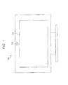
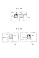
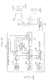
- Fig. 1 is a diagram illustrating a display system according to an embodiment.
- Fig. 1 is a front view of the display system viewed from the front.
- a display system 100 includes a display device 102 and an image pickup device 104, for example.
- the display device 102 is an example of a display device, and displays still images or moving images in accordance with driving signals.
- the display device 102 displays a still image or a moving image using liquid crystal.
- the display device 102 may display a still image or a moving image using self-luminous display device such as an organic EL (Electroluminescence).
- the image pickup device 104 which is an example of an image pickup device is disposed in an upper center portion of the display device 102 and captures a subject located in a display direction of the display device 102.
- the image pickup device 104 may take still images or moving images using a CCD (Charge Coupled Device) image sensor or may take still images or moving images using a CMOS (Complementary Metal Oxide Semiconductor) image sensor.
- CCD Charge Coupled Device
- CMOS Complementary Metal Oxide Semiconductor
- the image pickup device 104 is disposed in the upper center portion of the display device 102 in this embodiment, a location where the image pickup device 104 is disposed is not limited to the upper center portion of the display device 102.
- the image pickup device 104 may be disposed in a lower center portion of the display device 102.
- the single image pickup device 104 is disposed in this embodiment, the number of image pickup devices 104 is not limited to one.
- two or more image pickup devices 104 may be disposed.
- the display device 102 and the image pickup device 104 are integrally configured in this embodiment, the display device 102 and the image pickup device 104 may be separately configured.
- the display system 100 may include a sensor (not shown) which detects presence or absence of a user positioned in front of the display device 102 and a signal reception unit (not shown) capable of receiving a control signal through an infrared communication or a wireless communication from a remote controller (not shown). Furthermore, the sensor may detect a distance between the display device 102 and the user positioned in front of the display device 102.
- the display device 102 of this embodiment may display content corresponding to a still image or a moving image and images captured by other information processing apparatuses 500 and 700 shown in Fig. 2 in parallel which will be described hereinafter.
- the display device 102 may display content corresponding to a still image or a moving image in a content display region in a display screen and display images captured by the other information processing apparatuses 500 and 700 in a display region for displaying images captured by the information processing apparatuses 500 and 700 in the display screen.
- the content display region is an example of a first display region.
- the display region for displaying images captured by the other information processing apparatuses 500 and 700 is an example of a second display region.
- the image pickup device 104 of this embodiment may capture a still image and a moving image regarding a user A who is watching the display screen of the display device 102 shown in Fig. 2 .
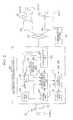
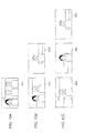
- FIG. 2 is a diagram illustrating a functional configuration of the information processing apparatus according to the first embodiment.
- Fig. 2 includes a display system 100 which transmits a captured image to an information processing apparatus 200 serving as the information processing apparatus according to this embodiment and which receives a signal for driving the display device 102 from the information processing apparatus 200 and a user A who uses the display system 100 and the information processing apparatus 200.
- Fig. 1 includes a display system 100 which transmits a captured image to an information processing apparatus 200 serving as the information processing apparatus according to this embodiment and which receives a signal for driving the display device 102 from the information processing apparatus 200 and a user A who uses the display system 100 and the information processing apparatus 200.
- the 2 includes a communication network 800 to which the information processing apparatus 200 is connectable, a communication server 300 and other information processing apparatuses 500 and 700 which are connectable the communication network 800, a display system 400 which transmits a captured image to the information processing apparatus 500 and which receives a signal from the information processing apparatus 500, users B and C who use the display system 400 and the information processing apparatus 500, a display system 600 which transmits a captured image to the information processing apparatus 700 and which receives a signal from the information processing apparatus 700, and a user D who uses the display system 600 and the information processing apparatus 700.
- the display systems 400 and 600 have the same configurations as the display system 100, and therefore, detailed descriptions thereof are omitted.
- the information processing apparatuses 500 and 700 have the same configurations as the information processing apparatus 200, and therefore, detailed descriptions thereof are omitted.
- the information processing apparatuses 500 and 700 are examples of communication object apparatuses.
- the information processing apparatus 200 includes an input unit 202, a detection unit 204, a head-count obtaining unit 206, a setting unit 208, a display image generation unit 210, a communication unit 212, an output unit 214, and a display controller 216.
- the input unit 202 receives a captured image which is generated by the image pickup device 104 through image capturing.
- the captured image generated by the image pickup device 104 through the image capturing is an example of another captured image.
- the input unit 202 transmits the received (input) captured image to the communication unit 212.
- the input unit 202 may transmit the received captured image to the detection unit 204 and the display image generation unit 210.
- the input unit 202 accepts an input for a setting of a display ratio of a display region for content to a display region for captured images supplied from the information processing apparatuses 500 and 700 in a display screen of the display device 102 performed by the user A, for example.
- the input unit 202 may accept an input for a setting of a display ratio of a display region for content to a display region for captured images supplied from the information processing apparatus 200, 500, and 700 in the display screen of the display device 102 performed by the user A. Then, the input unit 202 transmits information on the received input for a setting of a display ratio to the setting unit 208.
- the display region for captured images supplied from the information processing apparatuses 200, 500, and 700 is an example of a second display region.
- the detection unit 204 which is an example of a detection unit receives captured images which are supplied from the information processing apparatuses 500 and 700 and which are received by the communication unit 212 and detects face regions including faces of the users B, C, and D in the received captured images. Then, the detection unit 204 transmits information on the face regions as results of the detection to the head-count obtaining unit 206 and the display image generation unit 210. Note that the detection unit 204 may receive a captured image supplied from the input unit 202 and detect a face region including a face of the user A in the received captured image.
- the detection unit 204 may transmit information on the face region including the face of the user A as a result of the detection to the head-count obtaining unit 206, the display image generation unit 210, and the communication unit 212.
- a technique disclosed in Japanese Unexamined Patent Application Publication No. 2007-65766 and a technique disclosed in Japanese Unexamined Patent Application Publication No. 2005-44330 may be used for the detection of a face region performed on a captured image by the detection unit 204.
- the detection of a face region will be briefly described.
- a face position, a face size, and a face direction are individually detected in the received captured image.
- a portion corresponding to a face image may be extracted from the image.
- characteristic portions of the face face feature positions
- a method referred to as an AAM (Active Appearance Models) method may be used for the detection of the face feature positions.
- a face is identified in the image captured by the image pickup device 104.
- a technique disclosed in Japanese Unexamined Patent Application Publication No. 2007-65766 or a technique disclosed in Japanese Unexamined Patent Application Publication No. 2005-44330 may be used as a method for identifying a face, and therefore, a detailed description thereof is omitted here.
- a gender and an age of a face included in the received captured image may be determined.
- the face of the user included in the received captured image may be obtained from among the stored faces so as to specify the user.
- the head-count obtaining unit 206 which is an example of an obtaining unit receives information on the face regions including the faces of the users B, C, and D detected by the detection unit 204. Then, the head-count obtaining unit 206 obtains the number of users who use the information processing apparatuses 500 and 700 in accordance with the received information on the face regions. Thereafter, the head-count obtaining unit 206 transmits a result of the obtainment of the number of users who use the information processing apparatuses 500 and 700 to the display image generation unit 210.
- the head-count obtaining unit 206 may receive information on a face region including the face of the user A detected by the detection unit 204 and obtain the number of users who use the information processing apparatus 200 in accordance with received information on the face region including the face of the user A. Then, the head-count obtaining unit 206 may transmit a result of the obtainment of the number of users who use the information processing apparatus 200 to the display image generation unit 210 and the display controller 216.
- the head-count obtaining unit 206 may receive the information on the face regions and obtain the number of users who use the information processing apparatuses 500 and 700 in accordance with the received information on the face regions.
- the detection unit 204 described above may not detect the face regions including the faces of the users B, C and D in the captured images supplied from the information processing apparatuses 500 and 700.
- the setting unit 208 which is an example of a setting unit receives information on the input for the setting of the display ratio from the input unit 202 and sets the display region for content and a display region for captured images supplied from the information processing apparatuses 500 and 700 in the display screen of the display device 102 in accordance with the received information on the input for the setting of the display ratio. Furthermore, the setting unit 208 may set a display region for content and a display region for captured images supplied from the information processing apparatuses 200, 500, and 700 in the display screen of the display device 102 in accordance with the received information on the input for the setting of the display ratio.
- the setting unit 208 transmits information on the set display region for captured images to the display image generation unit 210 and the display controller 216 and transmits information on the set display region for content to the display controller 216.
- the setting unit 208 sets a size of the display region for content and a size of the display region for captured images supplied from the information processing apparatuses 500 and 700 in the display screen of the display device 102 and transmits information on the set size of the display region for content and information on the set size of the display region for captured images.
- the display image generation unit 210 which is an example of a generation unit receives information on the face regions including the faces of the users B, C, and D from the detection unit 204, receives the result of the obtainment of the number of users who use the information processing apparatuses 500 and 700 from the head-count obtaining unit 206, receives the information on the display region for captured images supplied from the information processing apparatuses 500 and 700 from the setting unit 208, and receives the image captured using the display system 400 and the image captured using the display system 600 which are received by the communication unit 212.
- the display image generation unit 210 generates a display image to be displayed in the display region for captured images supplied from the information processing apparatuses 500 and 700 included in the display screen of the display device 102 using the image captured by the display system 400 and the image captured by the display system 600. Thereafter, the display image generation unit 210 transmits the generated display image to the display controller 216.
- the display image generation unit 210 extracts a portion of the image captured by the display system 400 corresponding to one third of the display region for captured images such that at least face feature portions of the user B are included in the portion in accordance with the information on the face region including the face of the user B, the result of the obtainment of the number of users who use the information processing apparatuses 500 and 700, that is, information representing that the number of users is three, and the information on the display region for captured images supplied from the information processing apparatuses 500 and 700 such as information on the size of the display region.
- the display image generation unit 210 extracts a portion of the image captured by the display system 400 corresponding to one third of the display region for captured images such that at least face feature portions of the user C are included in the portion in accordance with the information on the face region including the face of the user C, the information representing that the number of users who use the information processing apparatuses 500 and 700 is three, and the information on the size of the display region for captured images supplied from the information processing apparatuses 500 and 700.
- the display image generation unit 210 extracts a portion of the image captured by the display system 600 corresponding to one third of the display region for captured images such that at least face feature portions of the user D are included in the portion in accordance with the information on the face region including the face of the user D, the information representing that the number of users who use the information processing apparatuses 500 and 700 is three, and the information on the size of the display region for captured images supplied from the information processing apparatuses 500 and 700.
- the display image generation unit 210 arranges the extracted captured images in the display region for captured images supplied from the information processing apparatuses 500 and 700 included in the display screen of the display device 102 such that the faces of the users who use the information processing apparatuses 500 and 700 are arranged in a horizontal direction, in a vertical direction, or in a matrix so that the display image described above is generated.
- the display image generation unit 210 may generate a display image to be displayed in the display region for captured images supplied from the information processing apparatuses 200, 500, and 700 included in the display screen of the display device 102 using the image captured by the display system 100, the image captured by the display system 400, and the image captured by the display system 600 in accordance with the received information on the face
- the display image generation unit 210 extracts a portion of the image captured by the display system 100 corresponding to a quarter of the display region for captured images such that at least face feature portions of the user A are included in the portion in accordance with the information on the face region including the face of the user A, the result of the obtainment of the number of users who use the information processing apparatuses 200, 500, and 700, that is, information representing that the number of users is four, and the information on the display region for captured images supplied from the information processing apparatuses 200, 500, and 700 such as the information on the size of the display region.
- the display image generation unit 210 extracts a portion of the image captured by the display system 400 corresponding to a quarter of the display region for captured images such that at least face feature portions of the user B are included in the portion in accordance with the information on the face region including the face of the user B, the information representing that the number of users who use the information processing apparatuses 200, 500, and 700 is four, and the information on the size of the display region for the captured images supplied from the information processing apparatuses 500 and 700.
- the display image generation unit 210 extracts a portion of the image captured by the display system 400 corresponding to a quarter of the display region for captured images such that at least face feature portions of the user C are included in the portion in accordance with the information on the face region including the face of the user C, the information representing that the number of users who use the information processing apparatuses 200, 500, and 700 is four, and the information on the size of the display region for captured images supplied from the information processing apparatuses 200, 500, and 700.
- the display image generation unit 210 extracts a portion of the image captured by the display system 600 corresponding to a quarter of the display region for captured images such that at least face feature portions of the user D are included in the portion in accordance with the information on the face region including the face of the user D, the information representing that the number of users who use the information processing apparatuses 200, 500, and 700 is four, and the information on the size of the display region for captured images supplied from the information processing apparatuses 200, 500, and 700.
- the display image generation unit 210 arranges the extracted captured images in the display region for captured images supplied from the information processing apparatuses 200, 500, and 700 included in the display screen of the display device 102 such that the faces of the users who use the information processing apparatuses 200, 500, and 700 are arranged in the horizontal direction, in the vertical direction, or in a matrix to thereby generate the display image described above.
- the display image generation unit 210 may receive the information on the face images and generate a display image in accordance with the information on the face regions received by the communication unit 212 instead of the information on the face regions detected by the detection unit 204.
- the display image generation unit 210 may extract portions of the captured images such that invalid regions which are wasted regions are not included in the display image in accordance with the received information on the face regions to thereby generate the display image. Moreover, the display image generation unit 210 may extract portions of the captured images such that the same portions which display the same images are not included in the display image to thereby generate the display image. In addition, the display image generation unit 210 may generate a display image regarding a plurality of users as a single user when the users are positioned near one another in a captured image in accordance with received information on face regions.
- the communication unit 212 which is an example of a reception unit receives an image captured using the display system 400 from the communication server 300 through the communication network 800. Furthermore, the communication unit 212 receives an image captured by the display system 600 from the communication server 300 through the communication network 800. Note that the communication unit 212 may directly receive an image captured by the display system 400 from the information processing apparatus 500 through the communication network 800. Similarly, the communication unit 212 may directly receive an image captured by the display system 600 from the information processing apparatus 700 through the communication network 800.
- the communication unit 212 may receive a captured image supplied from the input unit 202 and transmit the received captured image to the communication server 300 through the communication network 800. Furthermore, the communication unit 212 may receive the information on the face region including the user A detected in the image captured using the display system 100 by the detection unit 204 and transmit the received information on the face region to the communication server 300 through the communication network 800. Note that the communication unit 212 may directly transmit the received captured image and the information on the face region to the information processing apparatuses 500 and 700 through the communication network 800.
- the communication unit 212 may receive the information on the face regions including the faces of the users B and C detected in the image captured using the display system 400 and the information on the face region including the face of the user D detected in the image captured using the display system 600 from the communication server 300 through the communication network 800. Note that the communication unit 212 may directly receive the information on the face regions including the faces of the users B and C detected in the image captured using the display system 400 from the information processing apparatus 500 through the communication network 800. Similarly, the communication unit 212 may directly receive the information on the face region including the face of the user D detected in the image captured using the display system 600 from the information processing apparatus 700 through the communication network 800.
- the output unit 214 receives a signal used to drive the display device 102 from the display controller 216 and transmits the received signal to the display device 102.
- the display controller 216 which is an example of a controller receives information on the display region for content from the setting unit 208 and the information on the display region for captured images supplied from the information processing apparatuses 500 and 700. Furthermore, the display controller 216 receives content corresponding to a still image or a moving image. Then, the display controller 216 transmits a signal for displaying the display image generated by the display image generation unit 210 in the display region for captured images supplied from the information processing apparatuses 500 and 700 included in the display screen of the display device 102 to the output unit 214. Moreover, the display controller 216 transmits a signal for displaying content having a reduced image size in the display region for content in the display screen of the display device 102 to the output unit 214.
- the display controller 216 may transmit to the output unit 214 a signal for displaying the display image generated by the display image generation unit 210 in the display region for captured images supplied from the information processing apparatuses 200, 500, and 700 included in the display screen of the display device 102.
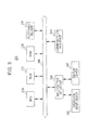
- FIG. 3 is a diagram illustrating a hardware configuration of the information processing apparatus 200 shown in Fig. 2 .
- the information processing apparatus 200 includes an MPU 230, a ROM 232, a RAM 234, a recording medium 236, an input/output interface 238, an operation input device 240, a display device 242, and a communication interface 244. Furthermore, in the information processing apparatus 200, the components are connected to one another through a bus 246 serving as a data transmission path.
- the MPU 230 includes an MPU (Micro Processing Unit) and an integrated circuit in which a plurality of circuits are integrated to realize various functions such as image processing and functions as a controller (not shown) which controls the entire information processing apparatus 200. Furthermore, in the information processing apparatus 200, the MPU 230 functions as the detection unit 204, the head-count obtaining unit 206, the setting unit 208, the display image generation unit 210, and the display controller 216.
- MPU Micro Processing Unit
- the MPU 230 functions as the detection unit 204, the head-count obtaining unit 206, the setting unit 208, the display image generation unit 210, and the display controller 216.
- the ROM 232 stores programs and control data such as calculation parameters used by the MPU 230.
- the RAM 234 temporarily stores programs executed by the MPU 230, for example.
- the recording medium 236 stores applications, for example.
- examples of the recording medium 236 include a magnetic recording medium such as a hard disk and a nonvolatile memory such as an EEPROM (Electrically Erasable and Programmable Read Only Memory), a flash memory, an MRAM (Magnetoresistive Random Access Memory), an FeRAM (Ferroelectric Random Access Memory), or a PRAM (Phase change Random Access Memory).
- the information processing apparatus 200 may include a recording medium 236 which is detachable from the information processing apparatus 200.
- the input/output interface 238 is connected to the operation input device 240 and the display device 242, for example. Furthermore, the input/output interface 238 functions as the input unit 202 and the output unit 214.
- the operation input device 240 functions as an operation unit (not shown), and the display device 242 functions as a display unit 254 which will be described with reference to Fig. 13 .
- examples of the input/output interface 238 include a USB (Universal Serial Bus) terminal, a DVI (Digital Visual Interface) terminal, an HDMI (High-Definition Multimedia Interface) terminal, and various processing circuits.
- the operation input device 240 is disposed on the information processing apparatus 200, for example, and is connected to the input/output interface 238 inside the information processing apparatus 200.
- Examples of the operation input device 240 include a button, a direction key, a rotatable selector such as a jog dial, and a combination thereof.
- the display device 242 is disposed on the information processing apparatus 200, for example, and is connected to the input/output interface 238 inside the information processing apparatus 200.
- Examples of the display device 242 include an LCD (Liquid Crystal Display) and an organic EL (ElectroLuminescence) display (which is also referred to as an OLED (Organic Light Emitting Diode) display).
- the input/output interface 238 may be connected to an operation input device (for example, a keyboard and a mouse) serving as an external apparatus of the information processing apparatus 200 and an external device such as a display device (for example, an external display device such as the display device 102) and an image pickup device (for example, the image pickup device 104).
- an operation input device for example, a keyboard and a mouse
- an external device such as a display device (for example, an external display device such as the display device 102) and an image pickup device (for example, the image pickup device 104).
- the display device 242 may be a device which is capable of performing display and which allows a user's operation, such as a touch screen.
- the communication interface 244 which is a communication unit included in the information processing apparatus 200 functions as the communication unit 212 which performs communication with an external apparatuses including the server 300 and the information processing apparatuses 500 and 700 through the network 800 (or directly) in a wireless/wired manner.
- the communication interface 244 include a combination of a communication antenna and an RF circuit (wireless communication), a combination of an IEEE802.15.1 port and a transmission/reception circuit (wireless communication), a combination of an IEEE802.11b port and a transmission/reception circuit (wireless communication), and a combination of a LAN terminal and a transmission/reception circuit (wired communication).
- the hardware configuration of the information processing apparatus 200 is not limited to the configuration shown in Fig. 3 .
- the information processing apparatus 200 may include an audio output device which serves as an audio output unit (not shown) and which includes a DSP (Digital Signal Processor), an amplifier, and a speaker.
- an audio output device which serves as an audio output unit (not shown) and which includes a DSP (Digital Signal Processor), an amplifier, and a speaker.
- DSP Digital Signal Processor
- the information processing apparatus 200 may include an image pickup device which serves as an image pickup unit 252 shown in Fig. 13 and which includes a lens-and-image pickup element, and a signal processing circuit.
- the information processing apparatus 200 may process a captured image generated by itself.
- the lens-and-image pickup element includes an optical lens and an image sensor including a plurality of image pickup elements such as CCD (Charge Coupled Device) sensors or CMOS (Complementary Metal Oxide Semiconductor) sensors.
- the signal processing circuit which includes an AGC (Automatic Gain Control) circuit and an ADC (Analog to Digital Converter) converts analog signals generated by the image pickup elements into digital signals (image data) and performs various signal processes. Examples of the signal processes performed by the signal processing circuit include a White Balance correction process, an interpolation process, a tone correction process, a gamma correction process, an YCbCr conversion process, an edge emphasizing process, and a coating process.
- the information processing apparatus 200 may not include the operation input device 240 and the display device 242 shown in Fig. 3 , for example.
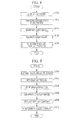
- FIG. 4 is a flowchart of the display process executed by the information processing apparatus 200 shown in Fig. 2 .
- Fig. 4 first, when the user A inputs an instruction for displaying content desired by the user A in the display device 102 using the information processing apparatus 200, the display controller 216 transmits a signal for displaying the content desired by the user A in the display screen of the display device 102 to the output unit 214 which transmits the received signal to the display device 102. By this, the content desired by the user A is displayed in the display screen of the display device 102 (step S100).
- the communication unit 212 enters a state in which the communication unit 212 may communicate with the communication server 300 through the communication network 800 (in step S102). Note that, in step S102, the communication unit 212 may enter a state in which the communication unit 212 may directly communicate with the information processing apparatuses 500 and 700 through the communication network 800.
- the communication unit 212 transmits a captured image which is generated through image capturing performed by the image pickup device 104 included in the display system 100 and which is received through the input unit 202 to the communication server 300 through the communication network 800 (in step S104).
- the communication unit 212 may transmit information on a face region including the face of the user A transmitted from the detection unit 204 to the communication server 300 through the communication network 800.
- the communication unit 212 may directly transmit the captured image or the information on the face region to the information processing apparatuses 500 and 700 through the communication network 800.
- the communication unit 212 receives an image which is captured by the display system 400 and which is transmitted from the information processing apparatus 500 through the communication server 300. Furthermore, the communication unit 212 receives an image which is captured by the display system 600 and which is transmitted from the information processing apparatus 700 through the communication server 300 (in step S106). Note that, in step S106, the information on the face regions including the faces of the users B and C detected in the image which is captured by the display system 400 and which is transmitted from the information processing apparatus 500 and the information on the face region including the face of the user D detected in the image which is captured by the display system 600 and which is transmitted from the information processing apparatus 700 may be received from the communication server 300. Furthermore, in step S106, the communication unit 212 may directly receive the captured images and the information on the face regions from the information processing apparatuses 500 and 700 through the communication network 800.
- the information processing apparatus 200 executes a parallel display process which will be described with reference to Fig. 5 (in step S108) so that the content desired by the user A and the captured images supplied from the information processing apparatuses 500 and 700 are displayed in parallel in the display screen of the display device 102, and thereafter, the process is terminated.
- Fig. 5 is a flowchart of the parallel display process performed in step S108 included in the display process shown in Fig. 4 .
- the head-count obtaining unit 206 obtains the number of users who use the information processing apparatuses 500 and 700 in accordance with the information on the face regions including the faces of the users B, C, and D detected by the detection unit 204 (in step S200). Note that, in step S200, the head-count obtaining unit 206 may obtain the number of users who use the information processing apparatus 200 in accordance with the information on the face region including the face of the user A detected by the detection unit 204.
- step S200 when the communication unit 212 receives the information on the face regions including the faces of the users B and C detected in the image captured by the display system 400 and the information on the face region including the face of the user D detected in the image captured by the display system 600, the number of users who use the information processing apparatuses 500 and 700 may be obtained in accordance with the information on the face regions.
- the setting unit 208 sets a display region for content and a display region for captured images supplied from the information processing apparatuses 500 and 700 in the display screen of the display device 102 in accordance with information on an input performed by the user A to set the display ratio of the display region for content to the display region for captured images supplied from the information processing apparatuses 500 and 700 in the display screen of the display device 102 (in step S202).
- the setting unit 208 may set the display region for content and the display region for captured images supplied from the information processing apparatuses 200, 500, and 700 in the display screen of the display device 102 in accordance with the information on an input performed by the user to set the display ratio of the display region for content to the display region for captured images supplied from the information processing apparatuses 200, 500, and 700 in the display screen of the display device 102.
- the display image generation unit 210 extracts portions of the image which is captured by the display system 400 and which is received by the communication unit 212 and a portion of the image which is captured by the display system 600 and which is received by the communication unit 212 in accordance with the information on the face regions including the faces of the users B, C, and D transmitted from the detection unit 204, a result of the obtainment of the number of users who use the information processing apparatuses 500 and 700 which is supplied from the head-count obtaining unit 206, and the information on the display region for captured images supplied from the information processing apparatuses 500 and 700 which is supplied from the setting unit 208 (in step S204), and generates a display image to be displayed in the display region for captured images supplied from the information processing apparatuses 500 and 700 in the display screen of the display device 102 (in step S206).
- the display image generation unit 210 may extract a portion of the image which is captured by the display system 100, portions of the image captured by the display system 400, and a portion of the image captured by the display system 600 in accordance with the information on the face region including the face of the user A transmitted from the detection unit 204, the information on the face regions including the faces of the users B, C, and D transmitted from the detection unit 204, a result of the obtainment of the number of users who use the information processing apparatus 200 which is supplied from the head-count obtaining unit 206, a result of the obtainment of the number of users who use the information processing apparatuses 500 and 700 which is supplied from the head-count obtaining unit 206, and the information on the display region for captured images supplied from the information processing apparatuses 200, 500, and 700 which is supplied from the setting unit 208, and generate a display image to be displayed in the display region for captured images supplied from the information processing apparatuses 200, 500, and 700 in the display screen of the display device 102
- step S204 and step S206 when the communication unit 212 receives the information on the face regions including the faces of the users B and C detected in the image captured by the display system 400 and the information on the face region including the face of the user D detected by in the image captured by the display system 600, the display image generation unit 210 may generate a display image in accordance with the information on the face regions supplied from the communication unit 212 instead of the information on the face regions detected by the detection unit 204.
- the display controller 216 transmits a signal for displaying the content which is desired by the user A and which has a reduced size in the display region for content included in the display screen of the display device 102 to the output unit 214 in accordance with the information on the display region for content supplied from the setting unit 208.
- the content desired by the user A which corresponds to the image having the reduced size is displayed in the display region for content in the display screen of the display device 102 (in step S208).
- the display controller 216 transmits a signal for displaying the display image generated by the display image generation unit 210 in the display region for captured images supplied from the information processing apparatuses 500 and 700 included in the display screen of the display device 102 to the output unit 214 in accordance with the information on the display region for the captured images supplied from the information processing apparatuses 500 and 700 which is received from the setting unit 208.
- the display image generated by the display image generation unit 210 is displayed in the display region for captured images, and accordingly, the content desired by the user A and the captured images supplied from the information processing apparatuses 500 and 700 are displayed in parallel (in step S210). Then, this process is terminated.
- the display controller 216 may transmit a signal for displaying the display image generated by the display image generation unit 210 in the display region for captured images supplied from the information processing apparatuses 200, 500, and 700 included in the display screen of the display device 102 to the output unit 214 in accordance with the information on the display region for captured images supplied from the information processing apparatuses 200, 500, and 700 which is supplied from the setting unit 208.
- the display image generated by the display image generation unit 210 is displayed in the display region for captured image, and accordingly, the content desired by the user A and the captured images supplied from the information processing apparatuses 200, 500, and 700 are displayed in parallel.
- the display image generated by the display image generation unit 210 is displayed in the display region for captured images, and the content desired by the user A which corresponds to the image having the reduced size is displayed in the display region for content.
- the display image to be displayed in the display region for captured image is generated by extracting portions of the captured images in accordance with the information on the face regions, the result of the obtainment of the number of users, and the information on the display region for captured images such as information on a size of the display region.
- the display image to be displayed in the display region for captured images is obtained by removing portions in the captured images which are wasted portions to identify the users, that is, obtained by removing large portions of backgrounds of the captured images, for example. Therefore, since portions of the captured images which are significant portions to identify the users such as portions of the captured images including face feature portions of the users are displayed in the display region for captured images even when the size of the display region for captured images is small, it is not difficult to identify the users. Furthermore, image quality of the display image is not deteriorated. Furthermore, since the image size of the content to be displayed in the content display region is reduced, it is unlikely that a portion of the content is hidden due to the display of the display image. Accordingly, the display of the content and the display of the captured images are appropriately performed in parallel.
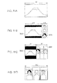
- Fig. 6 and Figs. 7A to 7D are diagrams for explanation of a first example.
- a case where content desired by a user who uses the display system 100 and an image captured by the display system 400 are displayed in parallel in the display screen of the display device 102 shown in Fig. 2 will be described. Note that, in this first example, a case where a single user uses the display system 400 will be described.
- Fig. 6 is a diagram illustrating an image captured by the display system 400.
- an image IM1 captured by the display system 400 is transmitted to the detection unit 204 included in the information processing apparatus 200 as described above, and the detection unit 204 detects a face region FA1 including a face of the user who uses the display system 400.
- Figs. 7A to 7D are diagrams illustrating content and a captured image supplied from the information processing apparatus 500 which are displayed in parallel in the display screen of the display device 102.
- Fig. 7B shows a case where a display ratio of the display region for content to the display region for captured images is A2:B2 (B2 ⁇ A2).
- a display image IM2 or IM4 which is generated by extracting a portion of the image IM1 is displayed in the display region for captured images and content IM3 or IM5 which is desired by the user who uses the display system 100 and which corresponds to an image having a reduced size is displayed in the display region for content.
- the user who uses the display system 100 may view the content IM3 or IM5 which is not partially hidden and easily identify the user who uses the display system 400 and whose face is included in the captured image.
- Fig. 8A and Figs. 9A to 9D are diagrams illustrating a second example.
- a case where content desired by a user who uses the display system 100 and an image captured by the display system 400 are displayed in parallel in the display screen of the display device 102 shown in Fig. 2 will be described. Note that, in the second example, a case where two users use the display system 400 will be described.
- Fig. 8A is a diagram illustrating an image captured by the display system 400 when two users use the display system 400.
- an image IM6 captured by the display system 400 is supplied to the detection unit 204 included in the information processing apparatus 200 as described above, and the detection unit 204 detects face regions FA2 and FA3 individually including faces of the two users who use the display system 400.
- Figs. 9A to 9D are diagrams illustrating content and a captured image supplied from the information processing apparatus 500 which are displayed in parallel in the display screen of the display device 102.
- Fig. 9B shows a case where a display ratio of the display region for content to the display region for captured images is A6:B6 (B6 ⁇ A6).
- a display image IM9 or IM11 which is generated by extracting a portion of the image IM6 is displayed in the display region for captured images and content IM10 or IM12 which is desired by the user who uses the display system 100 and which corresponds to an image having a reduced size is displayed in the display region for content.
- the user who uses the display system 100 may view the content IM10 or IM12 which is not partially hidden and easily identify the two users who use the display system 400 and whose faces are included in the captured image.
- Fig. 8B also in a case where, when a single user uses the display system 400 and a single user uses the display system 600, the content desired by the user who uses the display system 100 and images IM7 and IM8 captured by the display systems 400 and 600, respectively, are displayed in parallel, the content desired by the user and the images captured by the display systems 400 and 600 may be displayed in parallel in the display screen of the display device 102 as shown in Figs. 9A to 9D (specifically, Figs. 9B and 9C ).
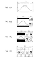
- Fig. 10A and Figs. 11A to 11D are diagrams illustrating a third example. Note that frames representing face regions are omitted in Fig. 10A and the following drawings.
- a case where content desired by a user who uses the display system 100 and an image captured by the display system 400 are displayed in parallel in the display screen of the display device 102 shown in Fig. 2 will be described. Note that a case where three users use the display system 400 will be described in the third example.
- Fig. 10A is a diagram illustrating an image captured by the display system 400 when three users use the display system 400.
- an image IM13 captured by the display system 400 is transmitted to the detection unit 204 included in the information processing apparatus 200 as described above, and the detection unit 204 detects face regions (not shown) individually including faces of the three users who use the display system 400.
- Figs. 11A to 11D are diagrams illustrating the content and an image captured by the information processing apparatus 500 which are displayed in parallel in the display screen of the display device 102.
- Fig. 11B shows a case where a display ratio of the display region for content to the display region for captured images is A10:B10 (B10 ⁇ A10).
- a display image IM19 or IM21 which is generated by extracting a portion of the image IM13 is displayed in the display region for captured images and content IM20 or IM22 which is desired by the user who uses the display system 100 and which corresponds to an image having a reduced size is displayed in the display region for content.
- the user who uses the display system 100 may view the content IM20 or IM22 which is not partially hidden and easily identify the three users who use the display system 400 and whose faces are included in the captured image.
- the content desired by the user who uses the display system 100 and images IM14 and IM15 captured by the display systems 400 and 600 may be displayed in parallel in the display screen included in the display device 102 as shown in Figs. 11A to 11D (specifically, Figs. 11B and 11C ).
- a single user uses the display system 400
- a single user uses the display system 600
- a single user uses another display system (not shown) as shown in Fig.
- the content desired by the user who uses the display system 100 and images IM16, IM17, IM18 captured by the display systems 400 and 600 and the other display system may be displayed in parallel in the display screen included in the display device 102 as shown in Figs. 11A to 11D (specifically, Figs. 11B and 11C ).
- Figs. 12A to 12D specifically, Figs. 12B and 12C
- the content desired by the user who use the display system 100 and images (not shown) captured by the display system 400 and the other systems may be displayed in parallel in the display screen included in the display device 102.
- Figs. 14A to 14C are diagrams illustrating a fourth example.
- a case where content desired by the user who uses the display system 100 and an image captured by the display system 400 are displayed in parallel in the display screen of the display device 102 shown in Fig. 2 will be described.
- Note that, in the fourth example, a case where a single user uses the display system 400 and the user is included in an end portion of an image captured by the display system 400 will be described.
- Fig. 14A is a diagram illustrating the image captured by the display system 400.
- an image IM23 captured by the display system 400 is transmitted to the detection unit 204 included in the information processing apparatus 200 as described above, and the detection unit 204 detects a face region FA4 including a face of the user who uses the display system 400.
- Figs. 14B and 14C are diagrams illustrating the content and the captured image supplied from the information processing apparatus 500 which are displayed in parallel in the display screen included in the display device 102.
- a display image IM24 generated by extracting a portion of the captured image IM23 is displayed in a display region for captured images and content IM25 which is desired by the user who uses the display system 100 and which has a reduced image size is displayed in a display region for content.
- the display image IM 24 displayed in the display region for captured images includes an invalid region R1 which is a wasted region.
- the portion of the captured image IM23 is extracted so that the invalid region R1 is not displayed in the display region for captured images whereby a display image IM26 is generated.
- a portion of the captured image IM23 is extracted using a right edge of the captured image IM23 as a reference so that the display image IM26 is generated. In this case, as shown in Fig.
- the display image IM26 which does not include the invalid region R1 is displayed in the display region for captured images and content IM27 which is desired by the user who uses the display system 100 and which has a reduced image size is displayed in the display region for content in the display screen of the display device 102. Accordingly, the user who uses the display system 100 may be prevented from having a feeling of strangeness and a discomfort feeling.
- Figs. 15A to 15D are diagrams illustrating a fifth example.
- a case where content desired by the user who uses the display system 100 and an image captured by the display system 400 are displayed in parallel in the display screen of the display device 102 shown in Fig. 2 will be described.
- Note that, in the fifth example, a case where two users use the display system 400 and the two users are positioned close to each other in an image captured by the display system 400 will be described.
- Fig. 15A is a diagram illustrating an image captured by the display system 400 when two users use the display system 400.
- an image IM28 captured by the display system 400 is transmitted to the detection unit 204 included in the information processing apparatus 200 as described above, and the detection unit 204 detects face regions FA5 and FA6 individually including faces of the two users who use the display system 400.
- Figs. 15B to 15D are diagrams illustrating the content and the captured image supplied from the information processing apparatus 500 which are displayed in parallel in the display screen of the display device 102.
- a display image IM29 generated by extracting portions of the captured image IM28 is displayed in a display region for captured images and content IM30 which is desired by the user who uses the display system 100 and which has a reduced image size is displayed in a display region for content.
- the display image IM29 in a case where the two users are positioned close to each other in the captured image, when the display image IM29 is generated by extracting portions of the captured image IM28 using the face regions FA5 and FA6 as centers, the display image IM29 includes an overlapping region R2 which includes the same images in the display region for captured images.
- a display image IM31 is generated by extracting portions of the captured images IM28 such that the overlapping region R2 is not displayed in the display region for captured images.
- the display image IM31 which does not include the overlapping region R2 is displayed in the display region for captured images
- content IM32 which is desired by the user who uses the display system 100 and which has a reduced image size is displayed in the display region for content in the display screen of the display device 102. Accordingly, the user who uses the display system 100 may be prevented from having a feeling of strangeness and a discomfort feeling.
- a display image IM33 may be generated by extracting a portion of the captured image IM28 so that at least face feature portions of the two users are included in the display image IM33.
- the display image IM33 which does not include the overlapping region R2 is displayed in the display region for captured images
- content IM34 which is desired by the user who uses the display system 100 and which has a reduced image size is displayed in the display region for content in the display screen of the display device 102.
- the display image IM33 shown in Fig. 15D is a single image, that is, an image generated by integrating the two images. Accordingly, the user who uses the display system 100 may be prevented from having a feeling of strangeness and a discomfort feeling.
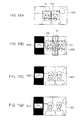
- Figs. 16A to 16F are diagrams illustrating a sixth example.
- a setting of a region to be extracted from a captured image will be described.
- Figs. 16A to 16F are diagrams illustrating a setting of a region to be extracted from a captured image.
- extraction region CA1, CA2, and CA3 are set using a vertical axis VA which passes the center of a face of a user as a reference as shown in Figs. 16A to 16C .
- extraction regions CA4, CA5, and CA6 may be set using the vertical line VA which passes the center of the face of the user and a horizontal axis HA which passes eyes in the face of the user, for example, as references as shown in Figs. 16D to 16F .
- FIG. 13 is a diagram illustrating the functional configuration of the information processing apparatus of this embodiment.
- An information processing apparatus 250 serving as the information processing apparatus of this embodiment is different from the information processing apparatus of the first embodiment described above only in that the information processing apparatus 250 includes an image pickup unit 252 and a display unit 254. Therefore, descriptions of redundant configurations and operations are omitted, and configurations and operations different from those of the first embodiment will be described hereinafter.
- a user A who uses the information processing apparatus 250, a communication network 800 to which the information processing apparatus 250 is connectable, a communication server 300 and information processing apparatuses 550 and 750 which are connectable to the communication network 800, users B and C who use the information processing apparatus 550, and a user D who uses the information processing apparatus 750 are shown.
- the information processing apparatuses 550 and 750 have the same configuration as the information processing apparatus 250, and therefore, detailed descriptions thereof are omitted.
- the information processing apparatus 250 includes the image pickup unit 252, a detection unit 204, a head-count obtaining unit 206, a setting unit 208, a display image generation unit 210, a communication unit 212, the display unit 254, and a display controller 216.
- the image pickup unit 252 is an example of an image pickup unit and may capture a still image or a moving image of a user A who watches a display screen of the display unit 254. Then, the image pickup unit 252 may transmit a captured image generated through image capturing to the communication unit 212, the detection unit 204, and display image generation unit 210.
- the display unit 254 is an example of a display unit and may display content of a still image or a moving image and captured images supplied from the information processing apparatuses 550 and 750 in parallel.
- the display unit 254 may display content of a still image or a moving image in a display region for content and display captured images supplied from the information processing apparatuses 550 and 750 in a display region for captured images supplied from the information processing apparatuses 550 and 750 in the display screen.
- an object may be achieved by supplying a storage medium, such as a non-transitory storage medium, which stores a program code of software which realizes functions of the foregoing embodiments to a system or an apparatus and reading and executing the program code stored in the storage medium using a computer (or a CPU, an MPU, or the like) of the system or the apparatus.
- a storage medium such as a non-transitory storage medium, which stores a program code of software which realizes functions of the foregoing embodiments to a system or an apparatus and reading and executing the program code stored in the storage medium using a computer (or a CPU, an MPU, or the like) of the system or the apparatus.
- the program code which is read from the storage medium realizes the functions of the foregoing embodiments, and the program code and the storage medium which stores the program code are included.
- examples of the storage medium to which the program code is supplied include a floppy (registered trademark) disk, a hard disk, a magneto-optical disc, an optical disc such as an CD-ROM, a CD-R, a CD-RW, a DVD-ROM, a DVD-RAM, a DVD-RW, or a DVD+RW, a magnetic tape, a nonvolatile memory card, and a ROM.
- the program code may be downloaded through a network.
- the present invention further includes embodiments where an OS (Operating System) operating in a computer performs a part of or entire actual process in accordance with an instruction of the program code and the functions of the foregoing embodiments.
- OS Operating System
- the present invention further includes embodiments where, after the program code read from the storage medium is written to a memory included in a function expansion board inserted into the computer or a function expansion unit connected to the computer, a CPU or the like included in the expansion board or the expansion unit executes a part of or entire actual process in accordance with an instruction of the program code and the functions of the foregoing embodiments are realized by the process.
- the communication server 300 may detect face regions including faces of users who use the information processing apparatuses 500 and 700 in captured images supplied from the information processing apparatuses 500 and 700.
- the information processing apparatus 200 may transmit content desired by the user A to the information processing apparatuses 500 and 700 so that the content is shared by the users.
Landscapes
- Engineering & Computer Science (AREA)
- Multimedia (AREA)
- Signal Processing (AREA)
- General Engineering & Computer Science (AREA)
- Computer Networks & Wireless Communication (AREA)
- Oral & Maxillofacial Surgery (AREA)
- Health & Medical Sciences (AREA)
- General Health & Medical Sciences (AREA)
- Computer Vision & Pattern Recognition (AREA)
- Human Computer Interaction (AREA)
- Physics & Mathematics (AREA)
- General Physics & Mathematics (AREA)
- Theoretical Computer Science (AREA)
- Two-Way Televisions, Distribution Of Moving Picture Or The Like (AREA)
- Controls And Circuits For Display Device (AREA)
- Studio Devices (AREA)
- Image Processing (AREA)
- Information Transfer Between Computers (AREA)
Applications Claiming Priority (2)
| Application Number | Priority Date | Filing Date | Title |
|---|---|---|---|
| JP2010221550 | 2010-09-30 | ||
| JP2010289780A JP5740972B2 (ja) | 2010-09-30 | 2010-12-27 | 情報処理装置および情報処理方法 |
Publications (3)
| Publication Number | Publication Date |
|---|---|
| EP2437490A2 true EP2437490A2 (de) | 2012-04-04 |
| EP2437490A3 EP2437490A3 (de) | 2013-10-16 |
| EP2437490B1 EP2437490B1 (de) | 2018-05-30 |
Family
ID=44651246
Family Applications (1)
| Application Number | Title | Priority Date | Filing Date |
|---|---|---|---|
| EP11180184.1A Active EP2437490B1 (de) | 2010-09-30 | 2011-09-06 | Informationsverarbeitungsvorrichtung und Informationsverarbeitungsverfahren |
Country Status (4)
| Country | Link |
|---|---|
| US (2) | US8953860B2 (de) |
| EP (1) | EP2437490B1 (de) |
| JP (1) | JP5740972B2 (de) |
| CN (1) | CN102446065B (de) |
Families Citing this family (10)
| Publication number | Priority date | Publication date | Assignee | Title |
|---|---|---|---|---|
| JP5740972B2 (ja) * | 2010-09-30 | 2015-07-01 | ソニー株式会社 | 情報処理装置および情報処理方法 |
| JP5598232B2 (ja) * | 2010-10-04 | 2014-10-01 | ソニー株式会社 | 情報処理装置、情報処理システムおよび情報処理方法 |
| JP6058978B2 (ja) * | 2012-11-19 | 2017-01-11 | サターン ライセンシング エルエルシーSaturn Licensing LLC | 画像処理装置及び画像処理方法、撮影装置、並びにコンピューター・プログラム |
| CN104798129B (zh) * | 2012-11-27 | 2018-10-19 | 索尼公司 | 显示装置、显示方法和计算机可读介质 |
| WO2014100770A2 (en) * | 2012-12-21 | 2014-06-26 | Sony Coputer Entertainment America Llc | Automatic generation of suggested mini-games for cloud-gaming based on recordes gameplay |
| CN104349131B (zh) * | 2013-08-09 | 2018-12-14 | 联想(北京)有限公司 | 一种信息处理方法及电子设备 |
| KR102192704B1 (ko) | 2013-10-22 | 2020-12-17 | 엘지전자 주식회사 | 영상 출력 장치 |
| KR102676837B1 (ko) * | 2016-12-16 | 2024-06-21 | 삼성전자주식회사 | 디스플레이장치 및 그 제어방법 |
| CN110430384B (zh) * | 2019-08-23 | 2020-11-03 | 珠海格力电器股份有限公司 | 视频通话方法、装置以及智能终端、存储介质 |
| TWI719800B (zh) * | 2020-01-08 | 2021-02-21 | 華碩電腦股份有限公司 | 可切換顯示模式的顯示裝置與方法 |
Citations (4)
| Publication number | Priority date | Publication date | Assignee | Title |
|---|---|---|---|---|
| JP2005044330A (ja) | 2003-07-24 | 2005-02-17 | Univ Of California San Diego | 弱仮説生成装置及び方法、学習装置及び方法、検出装置及び方法、表情学習装置及び方法、表情認識装置及び方法、並びにロボット装置 |
| JP2006050370A (ja) | 2004-08-06 | 2006-02-16 | Sony Corp | 情報処理装置および方法、記録媒体、並びにプログラム |
| JP2007065766A (ja) | 2005-08-29 | 2007-03-15 | Sony Corp | 画像処理装置および方法、並びにプログラム |
| JP2010221550A (ja) | 2009-03-24 | 2010-10-07 | Seiko Epson Corp | 偏心体の製造方法、偏心体 |
Family Cites Families (84)
| Publication number | Priority date | Publication date | Assignee | Title |
|---|---|---|---|---|
| US5657096A (en) * | 1995-05-03 | 1997-08-12 | Lukacs; Michael Edward | Real time video conferencing system and method with multilayer keying of multiple video images |
| JP2002032068A (ja) * | 2000-07-18 | 2002-01-31 | Olympus Optical Co Ltd | 画像処理装置 |
| US7155036B2 (en) * | 2000-12-04 | 2006-12-26 | Sony Corporation | Face detection under varying rotation |
| US20020081003A1 (en) * | 2000-12-27 | 2002-06-27 | Sobol Robert E. | System and method for automatically enhancing graphical images |
| US8218829B2 (en) * | 2001-08-20 | 2012-07-10 | Polycom, Inc. | System and method for using biometrics technology in conferencing |
| JP2003111040A (ja) * | 2001-09-28 | 2003-04-11 | Matsushita Electric Ind Co Ltd | 動画像通信方法及び動画像通信装置 |
| US7027101B1 (en) * | 2002-05-13 | 2006-04-11 | Microsoft Corporation | Selectively overlaying a user interface atop a video signal |
| US7598975B2 (en) * | 2002-06-21 | 2009-10-06 | Microsoft Corporation | Automatic face extraction for use in recorded meetings timelines |
| US7428000B2 (en) * | 2003-06-26 | 2008-09-23 | Microsoft Corp. | System and method for distributed meetings |
| JP2005039598A (ja) * | 2003-07-16 | 2005-02-10 | Nippon Telegr & Teleph Corp <Ntt> | インタラクティブ配信システム |
| US7092002B2 (en) * | 2003-09-19 | 2006-08-15 | Applied Minds, Inc. | Systems and method for enhancing teleconferencing collaboration |
| JP2005182196A (ja) * | 2003-12-16 | 2005-07-07 | Canon Inc | 画像表示方法および画像表示装置 |
| JP4716083B2 (ja) * | 2004-07-27 | 2011-07-06 | ソニー株式会社 | 情報処理装置および方法、記録媒体、並びにプログラム |
| US7554571B1 (en) * | 2005-03-18 | 2009-06-30 | Avaya Inc. | Dynamic layout of participants in a multi-party video conference |
| US20060222243A1 (en) * | 2005-04-02 | 2006-10-05 | Newell Martin E | Extraction and scaled display of objects in an image |
| TW200743385A (en) * | 2006-05-05 | 2007-11-16 | Amtran Technology Co Ltd | Method of audio-visual communication using television and television using the same |
| JP4832869B2 (ja) * | 2005-11-29 | 2011-12-07 | 京セラ株式会社 | 通信端末およびその表示方法 |
| WO2007063922A1 (ja) * | 2005-11-29 | 2007-06-07 | Kyocera Corporation | 通信端末および通信システム、並びに通信端末の表示方法 |
| JP5170961B2 (ja) * | 2006-02-01 | 2013-03-27 | ソニー株式会社 | 画像処理システム、画像処理装置および方法、プログラム、並びに記録媒体 |
| JP4844814B2 (ja) * | 2006-02-13 | 2011-12-28 | ソニー株式会社 | 撮影装置および方法、並びにプログラム |
| JP4767817B2 (ja) * | 2006-05-02 | 2011-09-07 | 株式会社ソニー・コンピュータエンタテインメント | 通信システム、通信装置、通信プログラム、通信プログラムを記憶したコンピュータ読み取り可能な記憶媒体 |
| US8791994B2 (en) * | 2006-06-29 | 2014-07-29 | Nikon Corporation | Replay device, replay system, and television set |
| JP2008085546A (ja) * | 2006-09-27 | 2008-04-10 | Funai Electric Co Ltd | 映像出力装置 |
| US7881505B2 (en) * | 2006-09-29 | 2011-02-01 | Pittsburgh Pattern Recognition, Inc. | Video retrieval system for human face content |
| US7847815B2 (en) * | 2006-10-11 | 2010-12-07 | Cisco Technology, Inc. | Interaction based on facial recognition of conference participants |
| JP2008158788A (ja) * | 2006-12-22 | 2008-07-10 | Fujifilm Corp | 情報処理装置および情報処理方法 |
| CN101601292B (zh) * | 2007-01-22 | 2011-11-16 | 索尼株式会社 | 信息处理装置、信息处理方法和程序 |
| JP4998026B2 (ja) * | 2007-03-15 | 2012-08-15 | ソニー株式会社 | 画像処理装置、撮像装置、および画像表示制御方法、並びにコンピュータ・プログラム |
| US8988609B2 (en) * | 2007-03-22 | 2015-03-24 | Sony Computer Entertainment America Llc | Scheme for determining the locations and timing of advertisements and other insertions in media |
| JP2008236679A (ja) * | 2007-03-23 | 2008-10-02 | Sony Corp | テレビ会議装置、制御方法、およびプログラム |
| US8615112B2 (en) * | 2007-03-30 | 2013-12-24 | Casio Computer Co., Ltd. | Image pickup apparatus equipped with face-recognition function |
| KR101513616B1 (ko) * | 2007-07-31 | 2015-04-20 | 엘지전자 주식회사 | 이동 단말기 및 그 영상정보 관리방법 |
| US8194117B2 (en) * | 2007-08-08 | 2012-06-05 | Qnx Software Systems Limited | Video phone system |
| CN103442201B (zh) * | 2007-09-24 | 2018-01-02 | 高通股份有限公司 | 用于语音和视频通信的增强接口 |
| US8788589B2 (en) * | 2007-10-12 | 2014-07-22 | Watchitoo, Inc. | System and method for coordinating simultaneous edits of shared digital data |
| JP4462334B2 (ja) * | 2007-11-16 | 2010-05-12 | ソニー株式会社 | 情報処理装置、情報処理方法、プログラム及び情報共有システム |
| JP5267062B2 (ja) * | 2007-11-16 | 2013-08-21 | ソニー株式会社 | 情報処理装置、情報処理方法、コンテンツ視聴装置、コンテンツ表示方法、プログラム及び情報共有システム |
| JP4322945B2 (ja) * | 2007-12-27 | 2009-09-02 | 株式会社東芝 | 電子機器、及び画像表示制御方法 |
| US8600120B2 (en) * | 2008-01-03 | 2013-12-03 | Apple Inc. | Personal computing device control using face detection and recognition |
| KR20090083108A (ko) * | 2008-01-29 | 2009-08-03 | 삼성전자주식회사 | 특정 영역이 확대된 영상을 촬영된 영상에 부가하는촬영방법 및 이를 적용한 촬영장치 |
| US20090210491A1 (en) * | 2008-02-20 | 2009-08-20 | Microsoft Corporation | Techniques to automatically identify participants for a multimedia conference event |
| JP4535150B2 (ja) * | 2008-03-18 | 2010-09-01 | ソニー株式会社 | 画像処理装置および方法、プログラム並びに記録媒体 |
| JP5087477B2 (ja) * | 2008-06-12 | 2012-12-05 | 株式会社日立製作所 | 情報記録再生装置および情報記録方法 |
| US7840638B2 (en) * | 2008-06-27 | 2010-11-23 | Microsoft Corporation | Participant positioning in multimedia conferencing |
| JP2010016482A (ja) * | 2008-07-01 | 2010-01-21 | Sony Corp | 情報処理装置および情報処理方法 |
| JP5248225B2 (ja) * | 2008-07-11 | 2013-07-31 | 富士フイルム株式会社 | コンテンツ表示装置、コンテンツ表示方法およびプログラム |
| GB2463110B (en) * | 2008-09-05 | 2013-01-16 | Skype | Communication system and method |
| JP2010087907A (ja) * | 2008-09-30 | 2010-04-15 | Canon Inc | 映像合成表示装置、映像表示システム及び映像表示方法 |
| US8345082B2 (en) * | 2008-10-08 | 2013-01-01 | Cisco Technology, Inc. | System and associated methodology for multi-layered site video conferencing |
| US20140229866A1 (en) * | 2008-11-24 | 2014-08-14 | Shindig, Inc. | Systems and methods for grouping participants of multi-user events |
| NO331287B1 (no) * | 2008-12-15 | 2011-11-14 | Cisco Systems Int Sarl | Fremgangsmate og anordning for gjenkjenning av ansikter i en videostrom |
| US20100225815A1 (en) * | 2009-03-05 | 2010-09-09 | Vishal Vincent Khatri | Systems methods and apparatuses for rendering user customizable multimedia signals on a display device |
| US8274544B2 (en) * | 2009-03-23 | 2012-09-25 | Eastman Kodak Company | Automated videography systems |
| US20100271457A1 (en) * | 2009-04-23 | 2010-10-28 | Optical Fusion Inc. | Advanced Video Conference |
| US9277021B2 (en) * | 2009-08-21 | 2016-03-01 | Avaya Inc. | Sending a user associated telecommunication address |
| US8208002B2 (en) * | 2009-08-27 | 2012-06-26 | Polycom, Inc. | Distance learning via instructor immersion into remote classroom |
| US20110096137A1 (en) * | 2009-10-27 | 2011-04-28 | Mary Baker | Audiovisual Feedback To Users Of Video Conferencing Applications |
| US8350891B2 (en) * | 2009-11-16 | 2013-01-08 | Lifesize Communications, Inc. | Determining a videoconference layout based on numbers of participants |
| JP2011107899A (ja) * | 2009-11-16 | 2011-06-02 | Sony Corp | 情報処理装置、設定変更方法及び設定変更プログラム |
| KR101681321B1 (ko) * | 2009-11-17 | 2016-11-30 | 엘지전자 주식회사 | 사용자 인증 방법 및 그를 이용한 화상 통신 장치 및 디스플레이 장치 |
| US9465451B2 (en) * | 2009-12-31 | 2016-10-11 | Flick Intelligence, LLC | Method, system and computer program product for obtaining and displaying supplemental data about a displayed movie, show, event or video game |
| US8483428B1 (en) * | 2010-01-06 | 2013-07-09 | Kimberly Lynn Anderson | Apparatus for processing a digital image |
| KR101673032B1 (ko) * | 2010-01-25 | 2016-11-04 | 엘지전자 주식회사 | 화상 통신 방법 및 그를 이용한 디지털 tv |
| US20110271197A1 (en) * | 2010-04-30 | 2011-11-03 | American Teleconferncing Services Ltd. | Distributing Information Between Participants in a Conference via a Conference User Interface |
| US20110271210A1 (en) * | 2010-04-30 | 2011-11-03 | American Teleconferncing Services Ltd. | Conferencing Application Store |
| US8462224B2 (en) * | 2010-06-01 | 2013-06-11 | Hewlett-Packard Development Company, L.P. | Image retrieval |
| US8270684B2 (en) * | 2010-07-27 | 2012-09-18 | Google Inc. | Automatic media sharing via shutter click |
| US8395655B2 (en) * | 2010-08-15 | 2013-03-12 | Hewlett-Packard Development Company, L.P. | System and method for enabling collaboration in a video conferencing system |
| JP5621421B2 (ja) * | 2010-09-06 | 2014-11-12 | ソニー株式会社 | 画像処理装置、プログラム及び画像処理方法 |
| JP5740972B2 (ja) * | 2010-09-30 | 2015-07-01 | ソニー株式会社 | 情報処理装置および情報処理方法 |
| JP2012085009A (ja) * | 2010-10-07 | 2012-04-26 | Sony Corp | 情報処理装置および情報処理方法 |
| EP2633474A4 (de) * | 2010-10-28 | 2017-03-22 | Telefonaktiebolaget LM Ericsson (publ) | Gerät zur erfassung von gesichtsdaten, videokonferenzvorrichtung für endbenutzer, verfahren, computerprogramm und computerprogrammprodukt zur extraktion von gesichtsdaten |
| JP2012113414A (ja) * | 2010-11-22 | 2012-06-14 | Sony Corp | 部位検出装置、部位検出方法、及びプログラム |
| JP5807399B2 (ja) * | 2011-06-13 | 2015-11-10 | ソニー株式会社 | 情報処理装置及びプログラム |
| US9153031B2 (en) * | 2011-06-22 | 2015-10-06 | Microsoft Technology Licensing, Llc | Modifying video regions using mobile device input |
| US8947497B2 (en) * | 2011-06-24 | 2015-02-03 | At&T Intellectual Property I, Lp | Apparatus and method for managing telepresence sessions |
| US8851990B2 (en) * | 2011-08-29 | 2014-10-07 | Bally Gaming, Inc. | Method and apparatus for audio scaling at a display showing content in different areas |
| KR101381439B1 (ko) * | 2011-09-15 | 2014-04-04 | 가부시끼가이샤 도시바 | 얼굴 인식 장치 및 얼굴 인식 방법 |
| US8810513B2 (en) * | 2012-02-02 | 2014-08-19 | Kodak Alaris Inc. | Method for controlling interactive display system |
| TWI488128B (zh) * | 2012-03-07 | 2015-06-11 | Altek Corp | 人臉辨識系統及其人臉辨識方法 |
| KR102004409B1 (ko) * | 2012-08-23 | 2019-07-29 | 삼성전자주식회사 | 플렉서블 디스플레이 장치 및 그 제어 방법 |
| US20130100238A1 (en) * | 2012-12-11 | 2013-04-25 | Vidtel, Inc. | Call routing based on facial recognition |
| WO2015058799A1 (en) * | 2013-10-24 | 2015-04-30 | Telefonaktiebolaget L M Ericsson (Publ) | Arrangements and method thereof for video retargeting for video conferencing |
| US10210598B2 (en) * | 2015-06-17 | 2019-02-19 | Samsung Electronics Co., Ltd. | Electronic device for displaying a plurality of images and method for processing an image |
-
2010
- 2010-12-27 JP JP2010289780A patent/JP5740972B2/ja not_active Expired - Fee Related
-
2011
- 2011-09-06 EP EP11180184.1A patent/EP2437490B1/de active Active
- 2011-09-19 US US13/235,609 patent/US8953860B2/en active Active
- 2011-09-22 CN CN201110282919.0A patent/CN102446065B/zh active Active
-
2014
- 2014-12-16 US US14/571,473 patent/US20150097920A1/en not_active Abandoned
Patent Citations (4)
| Publication number | Priority date | Publication date | Assignee | Title |
|---|---|---|---|---|
| JP2005044330A (ja) | 2003-07-24 | 2005-02-17 | Univ Of California San Diego | 弱仮説生成装置及び方法、学習装置及び方法、検出装置及び方法、表情学習装置及び方法、表情認識装置及び方法、並びにロボット装置 |
| JP2006050370A (ja) | 2004-08-06 | 2006-02-16 | Sony Corp | 情報処理装置および方法、記録媒体、並びにプログラム |
| JP2007065766A (ja) | 2005-08-29 | 2007-03-15 | Sony Corp | 画像処理装置および方法、並びにプログラム |
| JP2010221550A (ja) | 2009-03-24 | 2010-10-07 | Seiko Epson Corp | 偏心体の製造方法、偏心体 |
Also Published As
| Publication number | Publication date |
|---|---|
| EP2437490A3 (de) | 2013-10-16 |
| US20120082339A1 (en) | 2012-04-05 |
| CN102446065A (zh) | 2012-05-09 |
| EP2437490B1 (de) | 2018-05-30 |
| US8953860B2 (en) | 2015-02-10 |
| CN102446065B (zh) | 2017-10-10 |
| JP5740972B2 (ja) | 2015-07-01 |
| JP2012095258A (ja) | 2012-05-17 |
| US20150097920A1 (en) | 2015-04-09 |
Similar Documents
| Publication | Publication Date | Title |
|---|---|---|
| EP2437490B1 (de) | Informationsverarbeitungsvorrichtung und Informationsverarbeitungsverfahren | |
| US9171199B2 (en) | Information processing device and information processing method | |
| EP2431841B1 (de) | Informationsverarbeitungsvorrichtung und Informationsverarbeitungsverfahren | |
| US9507999B2 (en) | Image processing apparatus and program | |
| JP5625643B2 (ja) | 情報処理装置、および情報処理方法 | |
| US9426270B2 (en) | Control apparatus and control method to control volume of sound | |
| CN107392832A (zh) | 图像处理方法及相关产品 | |
| JP2013162287A (ja) | 画像処理装置、画像処理方法、およびプログラム | |
| CN102810308B (zh) | 显示控制装置、显示控制方法 | |
| US20160343158A1 (en) | Effect control device, effect control method, and program | |
| US20160171308A1 (en) | Electronic device and image processing method | |
| KR20150004052A (ko) | 리모트 컨트롤러 및 멀티미디어 디바이스의 제어 방법 | |
| JP2014209778A (ja) | 情報処理装置および情報処理方法 | |
| CN110662113A (zh) | 视频播放方法、装置和计算机可读存储介质 | |
| CN107027061A (zh) | 电视系统与多媒体播放方法 |
Legal Events
| Date | Code | Title | Description |
|---|---|---|---|
| PUAI | Public reference made under article 153(3) epc to a published international application that has entered the european phase |
Free format text: ORIGINAL CODE: 0009012 |
|
| 17P | Request for examination filed |
Effective date: 20110921 |
|
| AK | Designated contracting states |
Kind code of ref document: A2 Designated state(s): AL AT BE BG CH CY CZ DE DK EE ES FI FR GB GR HR HU IE IS IT LI LT LU LV MC MK MT NL NO PL PT RO RS SE SI SK SM TR |
|
| AX | Request for extension of the european patent |
Extension state: BA ME |
|
| PUAL | Search report despatched |
Free format text: ORIGINAL CODE: 0009013 |
|
| AK | Designated contracting states |
Kind code of ref document: A3 Designated state(s): AL AT BE BG CH CY CZ DE DK EE ES FI FR GB GR HR HU IE IS IT LI LT LU LV MC MK MT NL NO PL PT RO RS SE SI SK SM TR |
|
| AX | Request for extension of the european patent |
Extension state: BA ME |
|
| RIC1 | Information provided on ipc code assigned before grant |
Ipc: H04N 7/14 20060101AFI20130906BHEP Ipc: H04L 12/18 20060101ALI20130906BHEP Ipc: H04N 7/15 20060101ALI20130906BHEP |
|
| 17Q | First examination report despatched |
Effective date: 20160608 |
|
| 17Q | First examination report despatched |
Effective date: 20160608 |
|
| GRAP | Despatch of communication of intention to grant a patent |
Free format text: ORIGINAL CODE: EPIDOSNIGR1 |
|
| RIN1 | Information on inventor provided before grant (corrected) |
Inventor name: KONDO, MASAO Inventor name: SAKAI, YUSUKE |
|
| INTG | Intention to grant announced |
Effective date: 20170818 |
|
| RAP1 | Party data changed (applicant data changed or rights of an application transferred) |
Owner name: SATURN LICENSING LLC |
|
| GRAJ | Information related to disapproval of communication of intention to grant by the applicant or resumption of examination proceedings by the epo deleted |
Free format text: ORIGINAL CODE: EPIDOSDIGR1 |
|
| REG | Reference to a national code |
Ref country code: DE Ref legal event code: R079 Ref document number: 602011048729 Country of ref document: DE Free format text: PREVIOUS MAIN CLASS: H04N0007140000 Ipc: G06K0009000000 |
|
| GRAP | Despatch of communication of intention to grant a patent |
Free format text: ORIGINAL CODE: EPIDOSNIGR1 |
|
| INTC | Intention to grant announced (deleted) | ||
| RIC1 | Information provided on ipc code assigned before grant |
Ipc: H04N 7/15 20060101ALI20171220BHEP Ipc: G06K 9/00 20060101AFI20171220BHEP Ipc: H04L 12/18 20060101ALI20171220BHEP Ipc: H04N 7/14 20060101ALI20171220BHEP |
|
| INTG | Intention to grant announced |
Effective date: 20180109 |
|
| GRAS | Grant fee paid |
Free format text: ORIGINAL CODE: EPIDOSNIGR3 |
|
| GRAA | (expected) grant |
Free format text: ORIGINAL CODE: 0009210 |
|
| AK | Designated contracting states |
Kind code of ref document: B1 Designated state(s): AL AT BE BG CH CY CZ DE DK EE ES FI FR GB GR HR HU IE IS IT LI LT LU LV MC MK MT NL NO PL PT RO RS SE SI SK SM TR |
|
| REG | Reference to a national code |
Ref country code: GB Ref legal event code: FG4D |
|
| REG | Reference to a national code |
Ref country code: CH Ref legal event code: EP |
|
| REG | Reference to a national code |
Ref country code: AT Ref legal event code: REF Ref document number: 1004365 Country of ref document: AT Kind code of ref document: T Effective date: 20180615 |
|
| REG | Reference to a national code |
Ref country code: IE Ref legal event code: FG4D |
|
| REG | Reference to a national code |
Ref country code: DE Ref legal event code: R096 Ref document number: 602011048729 Country of ref document: DE |
|
| REG | Reference to a national code |
Ref country code: NL Ref legal event code: FP |
|
| REG | Reference to a national code |
Ref country code: FR Ref legal event code: PLFP Year of fee payment: 8 |
|
| REG | Reference to a national code |
Ref country code: LT Ref legal event code: MG4D |
|
| PG25 | Lapsed in a contracting state [announced via postgrant information from national office to epo] |
Ref country code: CY Free format text: LAPSE BECAUSE OF FAILURE TO SUBMIT A TRANSLATION OF THE DESCRIPTION OR TO PAY THE FEE WITHIN THE PRESCRIBED TIME-LIMIT Effective date: 20180530 Ref country code: LT Free format text: LAPSE BECAUSE OF FAILURE TO SUBMIT A TRANSLATION OF THE DESCRIPTION OR TO PAY THE FEE WITHIN THE PRESCRIBED TIME-LIMIT Effective date: 20180530 Ref country code: BG Free format text: LAPSE BECAUSE OF FAILURE TO SUBMIT A TRANSLATION OF THE DESCRIPTION OR TO PAY THE FEE WITHIN THE PRESCRIBED TIME-LIMIT Effective date: 20180830 Ref country code: FI Free format text: LAPSE BECAUSE OF FAILURE TO SUBMIT A TRANSLATION OF THE DESCRIPTION OR TO PAY THE FEE WITHIN THE PRESCRIBED TIME-LIMIT Effective date: 20180530 Ref country code: NO Free format text: LAPSE BECAUSE OF FAILURE TO SUBMIT A TRANSLATION OF THE DESCRIPTION OR TO PAY THE FEE WITHIN THE PRESCRIBED TIME-LIMIT Effective date: 20180830 Ref country code: SE Free format text: LAPSE BECAUSE OF FAILURE TO SUBMIT A TRANSLATION OF THE DESCRIPTION OR TO PAY THE FEE WITHIN THE PRESCRIBED TIME-LIMIT Effective date: 20180530 Ref country code: ES Free format text: LAPSE BECAUSE OF FAILURE TO SUBMIT A TRANSLATION OF THE DESCRIPTION OR TO PAY THE FEE WITHIN THE PRESCRIBED TIME-LIMIT Effective date: 20180530 |
|
| PG25 | Lapsed in a contracting state [announced via postgrant information from national office to epo] |
Ref country code: GR Free format text: LAPSE BECAUSE OF FAILURE TO SUBMIT A TRANSLATION OF THE DESCRIPTION OR TO PAY THE FEE WITHIN THE PRESCRIBED TIME-LIMIT Effective date: 20180831 Ref country code: HR Free format text: LAPSE BECAUSE OF FAILURE TO SUBMIT A TRANSLATION OF THE DESCRIPTION OR TO PAY THE FEE WITHIN THE PRESCRIBED TIME-LIMIT Effective date: 20180530 Ref country code: RS Free format text: LAPSE BECAUSE OF FAILURE TO SUBMIT A TRANSLATION OF THE DESCRIPTION OR TO PAY THE FEE WITHIN THE PRESCRIBED TIME-LIMIT Effective date: 20180530 Ref country code: LV Free format text: LAPSE BECAUSE OF FAILURE TO SUBMIT A TRANSLATION OF THE DESCRIPTION OR TO PAY THE FEE WITHIN THE PRESCRIBED TIME-LIMIT Effective date: 20180530 |
|
| REG | Reference to a national code |
Ref country code: AT Ref legal event code: MK05 Ref document number: 1004365 Country of ref document: AT Kind code of ref document: T Effective date: 20180530 |
|
| PG25 | Lapsed in a contracting state [announced via postgrant information from national office to epo] |
Ref country code: AT Free format text: LAPSE BECAUSE OF FAILURE TO SUBMIT A TRANSLATION OF THE DESCRIPTION OR TO PAY THE FEE WITHIN THE PRESCRIBED TIME-LIMIT Effective date: 20180530 Ref country code: DK Free format text: LAPSE BECAUSE OF FAILURE TO SUBMIT A TRANSLATION OF THE DESCRIPTION OR TO PAY THE FEE WITHIN THE PRESCRIBED TIME-LIMIT Effective date: 20180530 Ref country code: EE Free format text: LAPSE BECAUSE OF FAILURE TO SUBMIT A TRANSLATION OF THE DESCRIPTION OR TO PAY THE FEE WITHIN THE PRESCRIBED TIME-LIMIT Effective date: 20180530 Ref country code: RO Free format text: LAPSE BECAUSE OF FAILURE TO SUBMIT A TRANSLATION OF THE DESCRIPTION OR TO PAY THE FEE WITHIN THE PRESCRIBED TIME-LIMIT Effective date: 20180530 Ref country code: SK Free format text: LAPSE BECAUSE OF FAILURE TO SUBMIT A TRANSLATION OF THE DESCRIPTION OR TO PAY THE FEE WITHIN THE PRESCRIBED TIME-LIMIT Effective date: 20180530 Ref country code: CZ Free format text: LAPSE BECAUSE OF FAILURE TO SUBMIT A TRANSLATION OF THE DESCRIPTION OR TO PAY THE FEE WITHIN THE PRESCRIBED TIME-LIMIT Effective date: 20180530 Ref country code: PL Free format text: LAPSE BECAUSE OF FAILURE TO SUBMIT A TRANSLATION OF THE DESCRIPTION OR TO PAY THE FEE WITHIN THE PRESCRIBED TIME-LIMIT Effective date: 20180530 |
|
| PG25 | Lapsed in a contracting state [announced via postgrant information from national office to epo] |
Ref country code: SM Free format text: LAPSE BECAUSE OF FAILURE TO SUBMIT A TRANSLATION OF THE DESCRIPTION OR TO PAY THE FEE WITHIN THE PRESCRIBED TIME-LIMIT Effective date: 20180530 Ref country code: IT Free format text: LAPSE BECAUSE OF FAILURE TO SUBMIT A TRANSLATION OF THE DESCRIPTION OR TO PAY THE FEE WITHIN THE PRESCRIBED TIME-LIMIT Effective date: 20180530 |
|
| REG | Reference to a national code |
Ref country code: DE Ref legal event code: R097 Ref document number: 602011048729 Country of ref document: DE |
|
| PLBE | No opposition filed within time limit |
Free format text: ORIGINAL CODE: 0009261 |
|
| STAA | Information on the status of an ep patent application or granted ep patent |
Free format text: STATUS: NO OPPOSITION FILED WITHIN TIME LIMIT |
|
| PG25 | Lapsed in a contracting state [announced via postgrant information from national office to epo] |
Ref country code: MC Free format text: LAPSE BECAUSE OF FAILURE TO SUBMIT A TRANSLATION OF THE DESCRIPTION OR TO PAY THE FEE WITHIN THE PRESCRIBED TIME-LIMIT Effective date: 20180530 |
|
| REG | Reference to a national code |
Ref country code: CH Ref legal event code: PL |
|
| 26N | No opposition filed |
Effective date: 20190301 |
|
| PG25 | Lapsed in a contracting state [announced via postgrant information from national office to epo] |
Ref country code: SI Free format text: LAPSE BECAUSE OF FAILURE TO SUBMIT A TRANSLATION OF THE DESCRIPTION OR TO PAY THE FEE WITHIN THE PRESCRIBED TIME-LIMIT Effective date: 20180530 |
|
| REG | Reference to a national code |
Ref country code: BE Ref legal event code: MM Effective date: 20180930 |
|
| REG | Reference to a national code |
Ref country code: IE Ref legal event code: MM4A |
|
| PG25 | Lapsed in a contracting state [announced via postgrant information from national office to epo] |
Ref country code: LU Free format text: LAPSE BECAUSE OF NON-PAYMENT OF DUE FEES Effective date: 20180906 |
|
| PG25 | Lapsed in a contracting state [announced via postgrant information from national office to epo] |
Ref country code: IE Free format text: LAPSE BECAUSE OF NON-PAYMENT OF DUE FEES Effective date: 20180906 |
|
| PG25 | Lapsed in a contracting state [announced via postgrant information from national office to epo] |
Ref country code: LI Free format text: LAPSE BECAUSE OF NON-PAYMENT OF DUE FEES Effective date: 20180930 Ref country code: CH Free format text: LAPSE BECAUSE OF NON-PAYMENT OF DUE FEES Effective date: 20180930 Ref country code: BE Free format text: LAPSE BECAUSE OF NON-PAYMENT OF DUE FEES Effective date: 20180930 |
|
| PG25 | Lapsed in a contracting state [announced via postgrant information from national office to epo] |
Ref country code: AL Free format text: LAPSE BECAUSE OF FAILURE TO SUBMIT A TRANSLATION OF THE DESCRIPTION OR TO PAY THE FEE WITHIN THE PRESCRIBED TIME-LIMIT Effective date: 20180530 |
|
| PG25 | Lapsed in a contracting state [announced via postgrant information from national office to epo] |
Ref country code: MT Free format text: LAPSE BECAUSE OF NON-PAYMENT OF DUE FEES Effective date: 20180906 |
|
| PG25 | Lapsed in a contracting state [announced via postgrant information from national office to epo] |
Ref country code: TR Free format text: LAPSE BECAUSE OF FAILURE TO SUBMIT A TRANSLATION OF THE DESCRIPTION OR TO PAY THE FEE WITHIN THE PRESCRIBED TIME-LIMIT Effective date: 20180530 |
|
| PG25 | Lapsed in a contracting state [announced via postgrant information from national office to epo] |
Ref country code: PT Free format text: LAPSE BECAUSE OF FAILURE TO SUBMIT A TRANSLATION OF THE DESCRIPTION OR TO PAY THE FEE WITHIN THE PRESCRIBED TIME-LIMIT Effective date: 20180530 Ref country code: HU Free format text: LAPSE BECAUSE OF FAILURE TO SUBMIT A TRANSLATION OF THE DESCRIPTION OR TO PAY THE FEE WITHIN THE PRESCRIBED TIME-LIMIT; INVALID AB INITIO Effective date: 20110906 |
|
| PG25 | Lapsed in a contracting state [announced via postgrant information from national office to epo] |
Ref country code: MK Free format text: LAPSE BECAUSE OF NON-PAYMENT OF DUE FEES Effective date: 20180530 |
|
| PG25 | Lapsed in a contracting state [announced via postgrant information from national office to epo] |
Ref country code: IS Free format text: LAPSE BECAUSE OF FAILURE TO SUBMIT A TRANSLATION OF THE DESCRIPTION OR TO PAY THE FEE WITHIN THE PRESCRIBED TIME-LIMIT Effective date: 20180930 |
|
| REG | Reference to a national code |
Ref country code: DE Ref legal event code: R079 Ref document number: 602011048729 Country of ref document: DE Free format text: PREVIOUS MAIN CLASS: G06K0009000000 Ipc: G06V0010000000 |
|
| P01 | Opt-out of the competence of the unified patent court (upc) registered |
Effective date: 20230514 |
|
| PGFP | Annual fee paid to national office [announced via postgrant information from national office to epo] |
Ref country code: DE Payment date: 20250926 Year of fee payment: 15 |
|
| PGFP | Annual fee paid to national office [announced via postgrant information from national office to epo] |
Ref country code: NL Payment date: 20250925 Year of fee payment: 15 |
|
| PGFP | Annual fee paid to national office [announced via postgrant information from national office to epo] |
Ref country code: GB Payment date: 20250923 Year of fee payment: 15 |
|
| PGFP | Annual fee paid to national office [announced via postgrant information from national office to epo] |
Ref country code: FR Payment date: 20250925 Year of fee payment: 15 |