EP2437490A2 - Information processing apparatus and information processing method - Google Patents
Information processing apparatus and information processing method Download PDFInfo
- Publication number
- EP2437490A2 EP2437490A2 EP11180184A EP11180184A EP2437490A2 EP 2437490 A2 EP2437490 A2 EP 2437490A2 EP 11180184 A EP11180184 A EP 11180184A EP 11180184 A EP11180184 A EP 11180184A EP 2437490 A2 EP2437490 A2 EP 2437490A2
- Authority
- EP
- European Patent Office
- Prior art keywords
- display
- image
- information processing
- captured
- face
- Prior art date
- Legal status (The legal status is an assumption and is not a legal conclusion. Google has not performed a legal analysis and makes no representation as to the accuracy of the status listed.)
- Granted
Links
- 230000010365 information processing Effects 0.000 title claims abstract description 188
- 238000003672 processing method Methods 0.000 title claims description 4
- 238000001514 detection method Methods 0.000 claims abstract description 56
- 238000004891 communication Methods 0.000 claims description 97
- 239000011159 matrix material Substances 0.000 claims description 3
- 238000000034 method Methods 0.000 description 40
- 238000010586 diagram Methods 0.000 description 38
- 210000000887 face Anatomy 0.000 description 27
- 230000008569 process Effects 0.000 description 26
- 230000006870 function Effects 0.000 description 17
- 239000000284 extract Substances 0.000 description 11
- 101100272626 Drosophila melanogaster BomBc1 gene Proteins 0.000 description 6
- 238000012545 processing Methods 0.000 description 6
- 230000005540 biological transmission Effects 0.000 description 5
- 238000012937 correction Methods 0.000 description 3
- 238000012986 modification Methods 0.000 description 3
- 230000004048 modification Effects 0.000 description 3
- 230000000295 complement effect Effects 0.000 description 2
- 238000005401 electroluminescence Methods 0.000 description 2
- 238000000605 extraction Methods 0.000 description 2
- 239000004973 liquid crystal related substance Substances 0.000 description 2
- 229910044991 metal oxide Inorganic materials 0.000 description 2
- 150000004706 metal oxides Chemical class 0.000 description 2
- 230000003287 optical effect Effects 0.000 description 2
- 239000004065 semiconductor Substances 0.000 description 2
- 101100444028 Drosophila melanogaster Dso2 gene Proteins 0.000 description 1
- 101100072569 Drosophila melanogaster IM18 gene Proteins 0.000 description 1
- 101100072571 Pisum sativum IM30 gene Proteins 0.000 description 1
- 230000004075 alteration Effects 0.000 description 1
- 230000008859 change Effects 0.000 description 1
- 238000006243 chemical reaction Methods 0.000 description 1
- 238000000576 coating method Methods 0.000 description 1
- 238000013461 design Methods 0.000 description 1
- 230000000007 visual effect Effects 0.000 description 1
Images


Classifications
-
- H—ELECTRICITY
- H04—ELECTRIC COMMUNICATION TECHNIQUE
- H04N—PICTORIAL COMMUNICATION, e.g. TELEVISION
- H04N7/00—Television systems
- H04N7/14—Systems for two-way working
- H04N7/15—Conference systems
-
- G—PHYSICS
- G06—COMPUTING; CALCULATING OR COUNTING
- G06V—IMAGE OR VIDEO RECOGNITION OR UNDERSTANDING
- G06V40/00—Recognition of biometric, human-related or animal-related patterns in image or video data
- G06V40/10—Human or animal bodies, e.g. vehicle occupants or pedestrians; Body parts, e.g. hands
- G06V40/16—Human faces, e.g. facial parts, sketches or expressions
- G06V40/168—Feature extraction; Face representation
-
- H—ELECTRICITY
- H04—ELECTRIC COMMUNICATION TECHNIQUE
- H04L—TRANSMISSION OF DIGITAL INFORMATION, e.g. TELEGRAPHIC COMMUNICATION
- H04L12/00—Data switching networks
- H04L12/02—Details
- H04L12/16—Arrangements for providing special services to substations
- H04L12/18—Arrangements for providing special services to substations for broadcast or conference, e.g. multicast
- H04L12/1813—Arrangements for providing special services to substations for broadcast or conference, e.g. multicast for computer conferences, e.g. chat rooms
- H04L12/1827—Network arrangements for conference optimisation or adaptation
-
- H—ELECTRICITY
- H04—ELECTRIC COMMUNICATION TECHNIQUE
- H04N—PICTORIAL COMMUNICATION, e.g. TELEVISION
- H04N7/00—Television systems
- H04N7/14—Systems for two-way working
- H04N7/141—Systems for two-way working between two video terminals, e.g. videophone
- H04N7/147—Communication arrangements, e.g. identifying the communication as a video-communication, intermediate storage of the signals
Definitions
- the present invention relates to an information processing apparatus and an information processing method.
- a television receiver includes a network communication function which enables not only reception of video and audio content of a program from a broadcasting station and display of the content but also transmission of various information to and reception of various information from another receiver.
- Japanese Unexamined Patent Application Publication No. 2006-50370 discloses a technique of displaying, when a user views program content of television broadcasting using a television receiver, information on registered other users (such as thumbnail images of the other users, and names, channels, and video images of content viewed by the other users) together with the program content.
- a display device such as a television receiver
- a PIP (Picture in Picture) display method or a POP (Picture on Picture) display method is generally used.
- an information processing apparatus may include an obtaining unit to obtain a number of users from information on detection of a face region including a face in a captured image provided at the apparatus.
- the apparatus also may include a setting unit to set a display region for content and a display region for a captured image in a display screen.
- the apparatus may include a display image generation unit to generate a display image to be displayed in the display region for a captured image, in accordance with the information on the detection, the number of users, and the display region set for a captured image.
- a method may include obtaining a number of users from information on detection of a face region including a face in a captured image; setting a display region for content and a display region for a captured image in a display screen; and generating a display image to be displayed in the display region for a captured image, in accordance with the information on the detection, the number of users, and the display region set for a captured image.
- at least one of the obtaining, the setting and the generating may be by a processor.
- a non-transitory recording medium may be recorded with a computer-readable program having instructions executable by a processor.
- the program may include obtaining a number of users from information on detection of a face region including a face in a captured image; setting a display region for content and a display region for a captured image in a display screen; and generating a display image to be displayed in the display region for a captured image, in accordance with the information on the detection, the number of users, and the display region set for a captured image.
- display of content and display of a communication image may be appropriately performed in parallel.
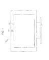
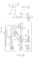
- Fig. 1 is a diagram illustrating a display system according to an embodiment.
- Fig. 1 is a front view of the display system viewed from the front.
- a display system 100 includes a display device 102 and an image pickup device 104, for example.
- the display device 102 is an example of a display device, and displays still images or moving images in accordance with driving signals.
- the display device 102 displays a still image or a moving image using liquid crystal.
- the display device 102 may display a still image or a moving image using self-luminous display device such as an organic EL (Electroluminescence).
- the image pickup device 104 which is an example of an image pickup device is disposed in an upper center portion of the display device 102 and captures a subject located in a display direction of the display device 102.
- the image pickup device 104 may take still images or moving images using a CCD (Charge Coupled Device) image sensor or may take still images or moving images using a CMOS (Complementary Metal Oxide Semiconductor) image sensor.
- CCD Charge Coupled Device
- CMOS Complementary Metal Oxide Semiconductor
- the image pickup device 104 is disposed in the upper center portion of the display device 102 in this embodiment, a location where the image pickup device 104 is disposed is not limited to the upper center portion of the display device 102.
- the image pickup device 104 may be disposed in a lower center portion of the display device 102.
- the single image pickup device 104 is disposed in this embodiment, the number of image pickup devices 104 is not limited to one.
- two or more image pickup devices 104 may be disposed.
- the display device 102 and the image pickup device 104 are integrally configured in this embodiment, the display device 102 and the image pickup device 104 may be separately configured.
- the display system 100 may include a sensor (not shown) which detects presence or absence of a user positioned in front of the display device 102 and a signal reception unit (not shown) capable of receiving a control signal through an infrared communication or a wireless communication from a remote controller (not shown). Furthermore, the sensor may detect a distance between the display device 102 and the user positioned in front of the display device 102.
- the display device 102 of this embodiment may display content corresponding to a still image or a moving image and images captured by other information processing apparatuses 500 and 700 shown in Fig. 2 in parallel which will be described hereinafter.
- the display device 102 may display content corresponding to a still image or a moving image in a content display region in a display screen and display images captured by the other information processing apparatuses 500 and 700 in a display region for displaying images captured by the information processing apparatuses 500 and 700 in the display screen.
- the content display region is an example of a first display region.
- the display region for displaying images captured by the other information processing apparatuses 500 and 700 is an example of a second display region.
- the image pickup device 104 of this embodiment may capture a still image and a moving image regarding a user A who is watching the display screen of the display device 102 shown in Fig. 2 .
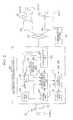
- FIG. 2 is a diagram illustrating a functional configuration of the information processing apparatus according to the first embodiment.
- Fig. 2 includes a display system 100 which transmits a captured image to an information processing apparatus 200 serving as the information processing apparatus according to this embodiment and which receives a signal for driving the display device 102 from the information processing apparatus 200 and a user A who uses the display system 100 and the information processing apparatus 200.
- Fig. 1 includes a display system 100 which transmits a captured image to an information processing apparatus 200 serving as the information processing apparatus according to this embodiment and which receives a signal for driving the display device 102 from the information processing apparatus 200 and a user A who uses the display system 100 and the information processing apparatus 200.
- the 2 includes a communication network 800 to which the information processing apparatus 200 is connectable, a communication server 300 and other information processing apparatuses 500 and 700 which are connectable the communication network 800, a display system 400 which transmits a captured image to the information processing apparatus 500 and which receives a signal from the information processing apparatus 500, users B and C who use the display system 400 and the information processing apparatus 500, a display system 600 which transmits a captured image to the information processing apparatus 700 and which receives a signal from the information processing apparatus 700, and a user D who uses the display system 600 and the information processing apparatus 700.
- the display systems 400 and 600 have the same configurations as the display system 100, and therefore, detailed descriptions thereof are omitted.
- the information processing apparatuses 500 and 700 have the same configurations as the information processing apparatus 200, and therefore, detailed descriptions thereof are omitted.
- the information processing apparatuses 500 and 700 are examples of communication object apparatuses.
- the information processing apparatus 200 includes an input unit 202, a detection unit 204, a head-count obtaining unit 206, a setting unit 208, a display image generation unit 210, a communication unit 212, an output unit 214, and a display controller 216.
- the input unit 202 receives a captured image which is generated by the image pickup device 104 through image capturing.
- the captured image generated by the image pickup device 104 through the image capturing is an example of another captured image.
- the input unit 202 transmits the received (input) captured image to the communication unit 212.
- the input unit 202 may transmit the received captured image to the detection unit 204 and the display image generation unit 210.
- the input unit 202 accepts an input for a setting of a display ratio of a display region for content to a display region for captured images supplied from the information processing apparatuses 500 and 700 in a display screen of the display device 102 performed by the user A, for example.
- the input unit 202 may accept an input for a setting of a display ratio of a display region for content to a display region for captured images supplied from the information processing apparatus 200, 500, and 700 in the display screen of the display device 102 performed by the user A. Then, the input unit 202 transmits information on the received input for a setting of a display ratio to the setting unit 208.
- the display region for captured images supplied from the information processing apparatuses 200, 500, and 700 is an example of a second display region.
- the detection unit 204 which is an example of a detection unit receives captured images which are supplied from the information processing apparatuses 500 and 700 and which are received by the communication unit 212 and detects face regions including faces of the users B, C, and D in the received captured images. Then, the detection unit 204 transmits information on the face regions as results of the detection to the head-count obtaining unit 206 and the display image generation unit 210. Note that the detection unit 204 may receive a captured image supplied from the input unit 202 and detect a face region including a face of the user A in the received captured image.
- the detection unit 204 may transmit information on the face region including the face of the user A as a result of the detection to the head-count obtaining unit 206, the display image generation unit 210, and the communication unit 212.
- a technique disclosed in Japanese Unexamined Patent Application Publication No. 2007-65766 and a technique disclosed in Japanese Unexamined Patent Application Publication No. 2005-44330 may be used for the detection of a face region performed on a captured image by the detection unit 204.
- the detection of a face region will be briefly described.
- a face position, a face size, and a face direction are individually detected in the received captured image.
- a portion corresponding to a face image may be extracted from the image.
- characteristic portions of the face face feature positions
- a method referred to as an AAM (Active Appearance Models) method may be used for the detection of the face feature positions.
- a face is identified in the image captured by the image pickup device 104.
- a technique disclosed in Japanese Unexamined Patent Application Publication No. 2007-65766 or a technique disclosed in Japanese Unexamined Patent Application Publication No. 2005-44330 may be used as a method for identifying a face, and therefore, a detailed description thereof is omitted here.
- a gender and an age of a face included in the received captured image may be determined.
- the face of the user included in the received captured image may be obtained from among the stored faces so as to specify the user.
- the head-count obtaining unit 206 which is an example of an obtaining unit receives information on the face regions including the faces of the users B, C, and D detected by the detection unit 204. Then, the head-count obtaining unit 206 obtains the number of users who use the information processing apparatuses 500 and 700 in accordance with the received information on the face regions. Thereafter, the head-count obtaining unit 206 transmits a result of the obtainment of the number of users who use the information processing apparatuses 500 and 700 to the display image generation unit 210.
- the head-count obtaining unit 206 may receive information on a face region including the face of the user A detected by the detection unit 204 and obtain the number of users who use the information processing apparatus 200 in accordance with received information on the face region including the face of the user A. Then, the head-count obtaining unit 206 may transmit a result of the obtainment of the number of users who use the information processing apparatus 200 to the display image generation unit 210 and the display controller 216.
- the head-count obtaining unit 206 may receive the information on the face regions and obtain the number of users who use the information processing apparatuses 500 and 700 in accordance with the received information on the face regions.
- the detection unit 204 described above may not detect the face regions including the faces of the users B, C and D in the captured images supplied from the information processing apparatuses 500 and 700.
- the setting unit 208 which is an example of a setting unit receives information on the input for the setting of the display ratio from the input unit 202 and sets the display region for content and a display region for captured images supplied from the information processing apparatuses 500 and 700 in the display screen of the display device 102 in accordance with the received information on the input for the setting of the display ratio. Furthermore, the setting unit 208 may set a display region for content and a display region for captured images supplied from the information processing apparatuses 200, 500, and 700 in the display screen of the display device 102 in accordance with the received information on the input for the setting of the display ratio.
- the setting unit 208 transmits information on the set display region for captured images to the display image generation unit 210 and the display controller 216 and transmits information on the set display region for content to the display controller 216.
- the setting unit 208 sets a size of the display region for content and a size of the display region for captured images supplied from the information processing apparatuses 500 and 700 in the display screen of the display device 102 and transmits information on the set size of the display region for content and information on the set size of the display region for captured images.
- the display image generation unit 210 which is an example of a generation unit receives information on the face regions including the faces of the users B, C, and D from the detection unit 204, receives the result of the obtainment of the number of users who use the information processing apparatuses 500 and 700 from the head-count obtaining unit 206, receives the information on the display region for captured images supplied from the information processing apparatuses 500 and 700 from the setting unit 208, and receives the image captured using the display system 400 and the image captured using the display system 600 which are received by the communication unit 212.
- the display image generation unit 210 generates a display image to be displayed in the display region for captured images supplied from the information processing apparatuses 500 and 700 included in the display screen of the display device 102 using the image captured by the display system 400 and the image captured by the display system 600. Thereafter, the display image generation unit 210 transmits the generated display image to the display controller 216.
- the display image generation unit 210 extracts a portion of the image captured by the display system 400 corresponding to one third of the display region for captured images such that at least face feature portions of the user B are included in the portion in accordance with the information on the face region including the face of the user B, the result of the obtainment of the number of users who use the information processing apparatuses 500 and 700, that is, information representing that the number of users is three, and the information on the display region for captured images supplied from the information processing apparatuses 500 and 700 such as information on the size of the display region.
- the display image generation unit 210 extracts a portion of the image captured by the display system 400 corresponding to one third of the display region for captured images such that at least face feature portions of the user C are included in the portion in accordance with the information on the face region including the face of the user C, the information representing that the number of users who use the information processing apparatuses 500 and 700 is three, and the information on the size of the display region for captured images supplied from the information processing apparatuses 500 and 700.
- the display image generation unit 210 extracts a portion of the image captured by the display system 600 corresponding to one third of the display region for captured images such that at least face feature portions of the user D are included in the portion in accordance with the information on the face region including the face of the user D, the information representing that the number of users who use the information processing apparatuses 500 and 700 is three, and the information on the size of the display region for captured images supplied from the information processing apparatuses 500 and 700.
- the display image generation unit 210 arranges the extracted captured images in the display region for captured images supplied from the information processing apparatuses 500 and 700 included in the display screen of the display device 102 such that the faces of the users who use the information processing apparatuses 500 and 700 are arranged in a horizontal direction, in a vertical direction, or in a matrix so that the display image described above is generated.
- the display image generation unit 210 may generate a display image to be displayed in the display region for captured images supplied from the information processing apparatuses 200, 500, and 700 included in the display screen of the display device 102 using the image captured by the display system 100, the image captured by the display system 400, and the image captured by the display system 600 in accordance with the received information on the face
- the display image generation unit 210 extracts a portion of the image captured by the display system 100 corresponding to a quarter of the display region for captured images such that at least face feature portions of the user A are included in the portion in accordance with the information on the face region including the face of the user A, the result of the obtainment of the number of users who use the information processing apparatuses 200, 500, and 700, that is, information representing that the number of users is four, and the information on the display region for captured images supplied from the information processing apparatuses 200, 500, and 700 such as the information on the size of the display region.
- the display image generation unit 210 extracts a portion of the image captured by the display system 400 corresponding to a quarter of the display region for captured images such that at least face feature portions of the user B are included in the portion in accordance with the information on the face region including the face of the user B, the information representing that the number of users who use the information processing apparatuses 200, 500, and 700 is four, and the information on the size of the display region for the captured images supplied from the information processing apparatuses 500 and 700.
- the display image generation unit 210 extracts a portion of the image captured by the display system 400 corresponding to a quarter of the display region for captured images such that at least face feature portions of the user C are included in the portion in accordance with the information on the face region including the face of the user C, the information representing that the number of users who use the information processing apparatuses 200, 500, and 700 is four, and the information on the size of the display region for captured images supplied from the information processing apparatuses 200, 500, and 700.
- the display image generation unit 210 extracts a portion of the image captured by the display system 600 corresponding to a quarter of the display region for captured images such that at least face feature portions of the user D are included in the portion in accordance with the information on the face region including the face of the user D, the information representing that the number of users who use the information processing apparatuses 200, 500, and 700 is four, and the information on the size of the display region for captured images supplied from the information processing apparatuses 200, 500, and 700.
- the display image generation unit 210 arranges the extracted captured images in the display region for captured images supplied from the information processing apparatuses 200, 500, and 700 included in the display screen of the display device 102 such that the faces of the users who use the information processing apparatuses 200, 500, and 700 are arranged in the horizontal direction, in the vertical direction, or in a matrix to thereby generate the display image described above.
- the display image generation unit 210 may receive the information on the face images and generate a display image in accordance with the information on the face regions received by the communication unit 212 instead of the information on the face regions detected by the detection unit 204.
- the display image generation unit 210 may extract portions of the captured images such that invalid regions which are wasted regions are not included in the display image in accordance with the received information on the face regions to thereby generate the display image. Moreover, the display image generation unit 210 may extract portions of the captured images such that the same portions which display the same images are not included in the display image to thereby generate the display image. In addition, the display image generation unit 210 may generate a display image regarding a plurality of users as a single user when the users are positioned near one another in a captured image in accordance with received information on face regions.
- the communication unit 212 which is an example of a reception unit receives an image captured using the display system 400 from the communication server 300 through the communication network 800. Furthermore, the communication unit 212 receives an image captured by the display system 600 from the communication server 300 through the communication network 800. Note that the communication unit 212 may directly receive an image captured by the display system 400 from the information processing apparatus 500 through the communication network 800. Similarly, the communication unit 212 may directly receive an image captured by the display system 600 from the information processing apparatus 700 through the communication network 800.
- the communication unit 212 may receive a captured image supplied from the input unit 202 and transmit the received captured image to the communication server 300 through the communication network 800. Furthermore, the communication unit 212 may receive the information on the face region including the user A detected in the image captured using the display system 100 by the detection unit 204 and transmit the received information on the face region to the communication server 300 through the communication network 800. Note that the communication unit 212 may directly transmit the received captured image and the information on the face region to the information processing apparatuses 500 and 700 through the communication network 800.
- the communication unit 212 may receive the information on the face regions including the faces of the users B and C detected in the image captured using the display system 400 and the information on the face region including the face of the user D detected in the image captured using the display system 600 from the communication server 300 through the communication network 800. Note that the communication unit 212 may directly receive the information on the face regions including the faces of the users B and C detected in the image captured using the display system 400 from the information processing apparatus 500 through the communication network 800. Similarly, the communication unit 212 may directly receive the information on the face region including the face of the user D detected in the image captured using the display system 600 from the information processing apparatus 700 through the communication network 800.
- the output unit 214 receives a signal used to drive the display device 102 from the display controller 216 and transmits the received signal to the display device 102.
- the display controller 216 which is an example of a controller receives information on the display region for content from the setting unit 208 and the information on the display region for captured images supplied from the information processing apparatuses 500 and 700. Furthermore, the display controller 216 receives content corresponding to a still image or a moving image. Then, the display controller 216 transmits a signal for displaying the display image generated by the display image generation unit 210 in the display region for captured images supplied from the information processing apparatuses 500 and 700 included in the display screen of the display device 102 to the output unit 214. Moreover, the display controller 216 transmits a signal for displaying content having a reduced image size in the display region for content in the display screen of the display device 102 to the output unit 214.
- the display controller 216 may transmit to the output unit 214 a signal for displaying the display image generated by the display image generation unit 210 in the display region for captured images supplied from the information processing apparatuses 200, 500, and 700 included in the display screen of the display device 102.
- FIG. 3 is a diagram illustrating a hardware configuration of the information processing apparatus 200 shown in Fig. 2 .
- the information processing apparatus 200 includes an MPU 230, a ROM 232, a RAM 234, a recording medium 236, an input/output interface 238, an operation input device 240, a display device 242, and a communication interface 244. Furthermore, in the information processing apparatus 200, the components are connected to one another through a bus 246 serving as a data transmission path.
- the MPU 230 includes an MPU (Micro Processing Unit) and an integrated circuit in which a plurality of circuits are integrated to realize various functions such as image processing and functions as a controller (not shown) which controls the entire information processing apparatus 200. Furthermore, in the information processing apparatus 200, the MPU 230 functions as the detection unit 204, the head-count obtaining unit 206, the setting unit 208, the display image generation unit 210, and the display controller 216.
- MPU Micro Processing Unit
- the MPU 230 functions as the detection unit 204, the head-count obtaining unit 206, the setting unit 208, the display image generation unit 210, and the display controller 216.
- the ROM 232 stores programs and control data such as calculation parameters used by the MPU 230.
- the RAM 234 temporarily stores programs executed by the MPU 230, for example.
- the recording medium 236 stores applications, for example.
- examples of the recording medium 236 include a magnetic recording medium such as a hard disk and a nonvolatile memory such as an EEPROM (Electrically Erasable and Programmable Read Only Memory), a flash memory, an MRAM (Magnetoresistive Random Access Memory), an FeRAM (Ferroelectric Random Access Memory), or a PRAM (Phase change Random Access Memory).
- the information processing apparatus 200 may include a recording medium 236 which is detachable from the information processing apparatus 200.
- the input/output interface 238 is connected to the operation input device 240 and the display device 242, for example. Furthermore, the input/output interface 238 functions as the input unit 202 and the output unit 214.
- the operation input device 240 functions as an operation unit (not shown), and the display device 242 functions as a display unit 254 which will be described with reference to Fig. 13 .
- examples of the input/output interface 238 include a USB (Universal Serial Bus) terminal, a DVI (Digital Visual Interface) terminal, an HDMI (High-Definition Multimedia Interface) terminal, and various processing circuits.
- the operation input device 240 is disposed on the information processing apparatus 200, for example, and is connected to the input/output interface 238 inside the information processing apparatus 200.
- Examples of the operation input device 240 include a button, a direction key, a rotatable selector such as a jog dial, and a combination thereof.
- the display device 242 is disposed on the information processing apparatus 200, for example, and is connected to the input/output interface 238 inside the information processing apparatus 200.
- Examples of the display device 242 include an LCD (Liquid Crystal Display) and an organic EL (ElectroLuminescence) display (which is also referred to as an OLED (Organic Light Emitting Diode) display).
- the input/output interface 238 may be connected to an operation input device (for example, a keyboard and a mouse) serving as an external apparatus of the information processing apparatus 200 and an external device such as a display device (for example, an external display device such as the display device 102) and an image pickup device (for example, the image pickup device 104).
- an operation input device for example, a keyboard and a mouse
- an external device such as a display device (for example, an external display device such as the display device 102) and an image pickup device (for example, the image pickup device 104).
- the display device 242 may be a device which is capable of performing display and which allows a user's operation, such as a touch screen.
- the communication interface 244 which is a communication unit included in the information processing apparatus 200 functions as the communication unit 212 which performs communication with an external apparatuses including the server 300 and the information processing apparatuses 500 and 700 through the network 800 (or directly) in a wireless/wired manner.
- the communication interface 244 include a combination of a communication antenna and an RF circuit (wireless communication), a combination of an IEEE802.15.1 port and a transmission/reception circuit (wireless communication), a combination of an IEEE802.11b port and a transmission/reception circuit (wireless communication), and a combination of a LAN terminal and a transmission/reception circuit (wired communication).
- the hardware configuration of the information processing apparatus 200 is not limited to the configuration shown in Fig. 3 .
- the information processing apparatus 200 may include an audio output device which serves as an audio output unit (not shown) and which includes a DSP (Digital Signal Processor), an amplifier, and a speaker.
- an audio output device which serves as an audio output unit (not shown) and which includes a DSP (Digital Signal Processor), an amplifier, and a speaker.
- DSP Digital Signal Processor
- the information processing apparatus 200 may include an image pickup device which serves as an image pickup unit 252 shown in Fig. 13 and which includes a lens-and-image pickup element, and a signal processing circuit.
- the information processing apparatus 200 may process a captured image generated by itself.
- the lens-and-image pickup element includes an optical lens and an image sensor including a plurality of image pickup elements such as CCD (Charge Coupled Device) sensors or CMOS (Complementary Metal Oxide Semiconductor) sensors.
- the signal processing circuit which includes an AGC (Automatic Gain Control) circuit and an ADC (Analog to Digital Converter) converts analog signals generated by the image pickup elements into digital signals (image data) and performs various signal processes. Examples of the signal processes performed by the signal processing circuit include a White Balance correction process, an interpolation process, a tone correction process, a gamma correction process, an YCbCr conversion process, an edge emphasizing process, and a coating process.
- the information processing apparatus 200 may not include the operation input device 240 and the display device 242 shown in Fig. 3 , for example.
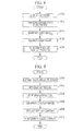
- FIG. 4 is a flowchart of the display process executed by the information processing apparatus 200 shown in Fig. 2 .
- Fig. 4 first, when the user A inputs an instruction for displaying content desired by the user A in the display device 102 using the information processing apparatus 200, the display controller 216 transmits a signal for displaying the content desired by the user A in the display screen of the display device 102 to the output unit 214 which transmits the received signal to the display device 102. By this, the content desired by the user A is displayed in the display screen of the display device 102 (step S100).
- the communication unit 212 enters a state in which the communication unit 212 may communicate with the communication server 300 through the communication network 800 (in step S102). Note that, in step S102, the communication unit 212 may enter a state in which the communication unit 212 may directly communicate with the information processing apparatuses 500 and 700 through the communication network 800.
- the communication unit 212 transmits a captured image which is generated through image capturing performed by the image pickup device 104 included in the display system 100 and which is received through the input unit 202 to the communication server 300 through the communication network 800 (in step S104).
- the communication unit 212 may transmit information on a face region including the face of the user A transmitted from the detection unit 204 to the communication server 300 through the communication network 800.
- the communication unit 212 may directly transmit the captured image or the information on the face region to the information processing apparatuses 500 and 700 through the communication network 800.
- the communication unit 212 receives an image which is captured by the display system 400 and which is transmitted from the information processing apparatus 500 through the communication server 300. Furthermore, the communication unit 212 receives an image which is captured by the display system 600 and which is transmitted from the information processing apparatus 700 through the communication server 300 (in step S106). Note that, in step S106, the information on the face regions including the faces of the users B and C detected in the image which is captured by the display system 400 and which is transmitted from the information processing apparatus 500 and the information on the face region including the face of the user D detected in the image which is captured by the display system 600 and which is transmitted from the information processing apparatus 700 may be received from the communication server 300. Furthermore, in step S106, the communication unit 212 may directly receive the captured images and the information on the face regions from the information processing apparatuses 500 and 700 through the communication network 800.
- the information processing apparatus 200 executes a parallel display process which will be described with reference to Fig. 5 (in step S108) so that the content desired by the user A and the captured images supplied from the information processing apparatuses 500 and 700 are displayed in parallel in the display screen of the display device 102, and thereafter, the process is terminated.
- Fig. 5 is a flowchart of the parallel display process performed in step S108 included in the display process shown in Fig. 4 .
- the head-count obtaining unit 206 obtains the number of users who use the information processing apparatuses 500 and 700 in accordance with the information on the face regions including the faces of the users B, C, and D detected by the detection unit 204 (in step S200). Note that, in step S200, the head-count obtaining unit 206 may obtain the number of users who use the information processing apparatus 200 in accordance with the information on the face region including the face of the user A detected by the detection unit 204.
- step S200 when the communication unit 212 receives the information on the face regions including the faces of the users B and C detected in the image captured by the display system 400 and the information on the face region including the face of the user D detected in the image captured by the display system 600, the number of users who use the information processing apparatuses 500 and 700 may be obtained in accordance with the information on the face regions.
- the setting unit 208 sets a display region for content and a display region for captured images supplied from the information processing apparatuses 500 and 700 in the display screen of the display device 102 in accordance with information on an input performed by the user A to set the display ratio of the display region for content to the display region for captured images supplied from the information processing apparatuses 500 and 700 in the display screen of the display device 102 (in step S202).
- the setting unit 208 may set the display region for content and the display region for captured images supplied from the information processing apparatuses 200, 500, and 700 in the display screen of the display device 102 in accordance with the information on an input performed by the user to set the display ratio of the display region for content to the display region for captured images supplied from the information processing apparatuses 200, 500, and 700 in the display screen of the display device 102.
- the display image generation unit 210 extracts portions of the image which is captured by the display system 400 and which is received by the communication unit 212 and a portion of the image which is captured by the display system 600 and which is received by the communication unit 212 in accordance with the information on the face regions including the faces of the users B, C, and D transmitted from the detection unit 204, a result of the obtainment of the number of users who use the information processing apparatuses 500 and 700 which is supplied from the head-count obtaining unit 206, and the information on the display region for captured images supplied from the information processing apparatuses 500 and 700 which is supplied from the setting unit 208 (in step S204), and generates a display image to be displayed in the display region for captured images supplied from the information processing apparatuses 500 and 700 in the display screen of the display device 102 (in step S206).
- the display image generation unit 210 may extract a portion of the image which is captured by the display system 100, portions of the image captured by the display system 400, and a portion of the image captured by the display system 600 in accordance with the information on the face region including the face of the user A transmitted from the detection unit 204, the information on the face regions including the faces of the users B, C, and D transmitted from the detection unit 204, a result of the obtainment of the number of users who use the information processing apparatus 200 which is supplied from the head-count obtaining unit 206, a result of the obtainment of the number of users who use the information processing apparatuses 500 and 700 which is supplied from the head-count obtaining unit 206, and the information on the display region for captured images supplied from the information processing apparatuses 200, 500, and 700 which is supplied from the setting unit 208, and generate a display image to be displayed in the display region for captured images supplied from the information processing apparatuses 200, 500, and 700 in the display screen of the display device 102
- step S204 and step S206 when the communication unit 212 receives the information on the face regions including the faces of the users B and C detected in the image captured by the display system 400 and the information on the face region including the face of the user D detected by in the image captured by the display system 600, the display image generation unit 210 may generate a display image in accordance with the information on the face regions supplied from the communication unit 212 instead of the information on the face regions detected by the detection unit 204.
- the display controller 216 transmits a signal for displaying the content which is desired by the user A and which has a reduced size in the display region for content included in the display screen of the display device 102 to the output unit 214 in accordance with the information on the display region for content supplied from the setting unit 208.
- the content desired by the user A which corresponds to the image having the reduced size is displayed in the display region for content in the display screen of the display device 102 (in step S208).
- the display controller 216 transmits a signal for displaying the display image generated by the display image generation unit 210 in the display region for captured images supplied from the information processing apparatuses 500 and 700 included in the display screen of the display device 102 to the output unit 214 in accordance with the information on the display region for the captured images supplied from the information processing apparatuses 500 and 700 which is received from the setting unit 208.
- the display image generated by the display image generation unit 210 is displayed in the display region for captured images, and accordingly, the content desired by the user A and the captured images supplied from the information processing apparatuses 500 and 700 are displayed in parallel (in step S210). Then, this process is terminated.
- the display controller 216 may transmit a signal for displaying the display image generated by the display image generation unit 210 in the display region for captured images supplied from the information processing apparatuses 200, 500, and 700 included in the display screen of the display device 102 to the output unit 214 in accordance with the information on the display region for captured images supplied from the information processing apparatuses 200, 500, and 700 which is supplied from the setting unit 208.
- the display image generated by the display image generation unit 210 is displayed in the display region for captured image, and accordingly, the content desired by the user A and the captured images supplied from the information processing apparatuses 200, 500, and 700 are displayed in parallel.
- the display image generated by the display image generation unit 210 is displayed in the display region for captured images, and the content desired by the user A which corresponds to the image having the reduced size is displayed in the display region for content.
- the display image to be displayed in the display region for captured image is generated by extracting portions of the captured images in accordance with the information on the face regions, the result of the obtainment of the number of users, and the information on the display region for captured images such as information on a size of the display region.
- the display image to be displayed in the display region for captured images is obtained by removing portions in the captured images which are wasted portions to identify the users, that is, obtained by removing large portions of backgrounds of the captured images, for example. Therefore, since portions of the captured images which are significant portions to identify the users such as portions of the captured images including face feature portions of the users are displayed in the display region for captured images even when the size of the display region for captured images is small, it is not difficult to identify the users. Furthermore, image quality of the display image is not deteriorated. Furthermore, since the image size of the content to be displayed in the content display region is reduced, it is unlikely that a portion of the content is hidden due to the display of the display image. Accordingly, the display of the content and the display of the captured images are appropriately performed in parallel.
- Fig. 6 and Figs. 7A to 7D are diagrams for explanation of a first example.
- a case where content desired by a user who uses the display system 100 and an image captured by the display system 400 are displayed in parallel in the display screen of the display device 102 shown in Fig. 2 will be described. Note that, in this first example, a case where a single user uses the display system 400 will be described.
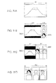
- Fig. 6 is a diagram illustrating an image captured by the display system 400.
- an image IM1 captured by the display system 400 is transmitted to the detection unit 204 included in the information processing apparatus 200 as described above, and the detection unit 204 detects a face region FA1 including a face of the user who uses the display system 400.
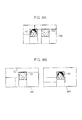
- Figs. 7A to 7D are diagrams illustrating content and a captured image supplied from the information processing apparatus 500 which are displayed in parallel in the display screen of the display device 102.
- Fig. 7B shows a case where a display ratio of the display region for content to the display region for captured images is A2:B2 (B2 ⁇ A2).
- a display image IM2 or IM4 which is generated by extracting a portion of the image IM1 is displayed in the display region for captured images and content IM3 or IM5 which is desired by the user who uses the display system 100 and which corresponds to an image having a reduced size is displayed in the display region for content.
- the user who uses the display system 100 may view the content IM3 or IM5 which is not partially hidden and easily identify the user who uses the display system 400 and whose face is included in the captured image.
- Fig. 8A and Figs. 9A to 9D are diagrams illustrating a second example.
- a case where content desired by a user who uses the display system 100 and an image captured by the display system 400 are displayed in parallel in the display screen of the display device 102 shown in Fig. 2 will be described. Note that, in the second example, a case where two users use the display system 400 will be described.
- Fig. 8A is a diagram illustrating an image captured by the display system 400 when two users use the display system 400.
- an image IM6 captured by the display system 400 is supplied to the detection unit 204 included in the information processing apparatus 200 as described above, and the detection unit 204 detects face regions FA2 and FA3 individually including faces of the two users who use the display system 400.
- Figs. 9A to 9D are diagrams illustrating content and a captured image supplied from the information processing apparatus 500 which are displayed in parallel in the display screen of the display device 102.
- Fig. 9B shows a case where a display ratio of the display region for content to the display region for captured images is A6:B6 (B6 ⁇ A6).
- a display image IM9 or IM11 which is generated by extracting a portion of the image IM6 is displayed in the display region for captured images and content IM10 or IM12 which is desired by the user who uses the display system 100 and which corresponds to an image having a reduced size is displayed in the display region for content.
- the user who uses the display system 100 may view the content IM10 or IM12 which is not partially hidden and easily identify the two users who use the display system 400 and whose faces are included in the captured image.
- Fig. 8B also in a case where, when a single user uses the display system 400 and a single user uses the display system 600, the content desired by the user who uses the display system 100 and images IM7 and IM8 captured by the display systems 400 and 600, respectively, are displayed in parallel, the content desired by the user and the images captured by the display systems 400 and 600 may be displayed in parallel in the display screen of the display device 102 as shown in Figs. 9A to 9D (specifically, Figs. 9B and 9C ).
- Fig. 10A and Figs. 11A to 11D are diagrams illustrating a third example. Note that frames representing face regions are omitted in Fig. 10A and the following drawings.
- a case where content desired by a user who uses the display system 100 and an image captured by the display system 400 are displayed in parallel in the display screen of the display device 102 shown in Fig. 2 will be described. Note that a case where three users use the display system 400 will be described in the third example.
- Fig. 10A is a diagram illustrating an image captured by the display system 400 when three users use the display system 400.
- an image IM13 captured by the display system 400 is transmitted to the detection unit 204 included in the information processing apparatus 200 as described above, and the detection unit 204 detects face regions (not shown) individually including faces of the three users who use the display system 400.
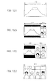
- Figs. 11A to 11D are diagrams illustrating the content and an image captured by the information processing apparatus 500 which are displayed in parallel in the display screen of the display device 102.
- Fig. 11B shows a case where a display ratio of the display region for content to the display region for captured images is A10:B10 (B10 ⁇ A10).
- a display image IM19 or IM21 which is generated by extracting a portion of the image IM13 is displayed in the display region for captured images and content IM20 or IM22 which is desired by the user who uses the display system 100 and which corresponds to an image having a reduced size is displayed in the display region for content.
- the user who uses the display system 100 may view the content IM20 or IM22 which is not partially hidden and easily identify the three users who use the display system 400 and whose faces are included in the captured image.
- the content desired by the user who uses the display system 100 and images IM14 and IM15 captured by the display systems 400 and 600 may be displayed in parallel in the display screen included in the display device 102 as shown in Figs. 11A to 11D (specifically, Figs. 11B and 11C ).
- a single user uses the display system 400
- a single user uses the display system 600
- a single user uses another display system (not shown) as shown in Fig.
- the content desired by the user who uses the display system 100 and images IM16, IM17, IM18 captured by the display systems 400 and 600 and the other display system may be displayed in parallel in the display screen included in the display device 102 as shown in Figs. 11A to 11D (specifically, Figs. 11B and 11C ).
- Figs. 12A to 12D specifically, Figs. 12B and 12C
- the content desired by the user who use the display system 100 and images (not shown) captured by the display system 400 and the other systems may be displayed in parallel in the display screen included in the display device 102.
- Figs. 14A to 14C are diagrams illustrating a fourth example.
- a case where content desired by the user who uses the display system 100 and an image captured by the display system 400 are displayed in parallel in the display screen of the display device 102 shown in Fig. 2 will be described.
- Note that, in the fourth example, a case where a single user uses the display system 400 and the user is included in an end portion of an image captured by the display system 400 will be described.
- Fig. 14A is a diagram illustrating the image captured by the display system 400.
- an image IM23 captured by the display system 400 is transmitted to the detection unit 204 included in the information processing apparatus 200 as described above, and the detection unit 204 detects a face region FA4 including a face of the user who uses the display system 400.
- Figs. 14B and 14C are diagrams illustrating the content and the captured image supplied from the information processing apparatus 500 which are displayed in parallel in the display screen included in the display device 102.
- a display image IM24 generated by extracting a portion of the captured image IM23 is displayed in a display region for captured images and content IM25 which is desired by the user who uses the display system 100 and which has a reduced image size is displayed in a display region for content.
- the display image IM 24 displayed in the display region for captured images includes an invalid region R1 which is a wasted region.
- the portion of the captured image IM23 is extracted so that the invalid region R1 is not displayed in the display region for captured images whereby a display image IM26 is generated.
- a portion of the captured image IM23 is extracted using a right edge of the captured image IM23 as a reference so that the display image IM26 is generated. In this case, as shown in Fig.
- the display image IM26 which does not include the invalid region R1 is displayed in the display region for captured images and content IM27 which is desired by the user who uses the display system 100 and which has a reduced image size is displayed in the display region for content in the display screen of the display device 102. Accordingly, the user who uses the display system 100 may be prevented from having a feeling of strangeness and a discomfort feeling.
- Figs. 15A to 15D are diagrams illustrating a fifth example.
- a case where content desired by the user who uses the display system 100 and an image captured by the display system 400 are displayed in parallel in the display screen of the display device 102 shown in Fig. 2 will be described.
- Note that, in the fifth example, a case where two users use the display system 400 and the two users are positioned close to each other in an image captured by the display system 400 will be described.
- Fig. 15A is a diagram illustrating an image captured by the display system 400 when two users use the display system 400.
- an image IM28 captured by the display system 400 is transmitted to the detection unit 204 included in the information processing apparatus 200 as described above, and the detection unit 204 detects face regions FA5 and FA6 individually including faces of the two users who use the display system 400.
- Figs. 15B to 15D are diagrams illustrating the content and the captured image supplied from the information processing apparatus 500 which are displayed in parallel in the display screen of the display device 102.
- a display image IM29 generated by extracting portions of the captured image IM28 is displayed in a display region for captured images and content IM30 which is desired by the user who uses the display system 100 and which has a reduced image size is displayed in a display region for content.
- the display image IM29 in a case where the two users are positioned close to each other in the captured image, when the display image IM29 is generated by extracting portions of the captured image IM28 using the face regions FA5 and FA6 as centers, the display image IM29 includes an overlapping region R2 which includes the same images in the display region for captured images.
- a display image IM31 is generated by extracting portions of the captured images IM28 such that the overlapping region R2 is not displayed in the display region for captured images.
- the display image IM31 which does not include the overlapping region R2 is displayed in the display region for captured images
- content IM32 which is desired by the user who uses the display system 100 and which has a reduced image size is displayed in the display region for content in the display screen of the display device 102. Accordingly, the user who uses the display system 100 may be prevented from having a feeling of strangeness and a discomfort feeling.
- a display image IM33 may be generated by extracting a portion of the captured image IM28 so that at least face feature portions of the two users are included in the display image IM33.
- the display image IM33 which does not include the overlapping region R2 is displayed in the display region for captured images
- content IM34 which is desired by the user who uses the display system 100 and which has a reduced image size is displayed in the display region for content in the display screen of the display device 102.
- the display image IM33 shown in Fig. 15D is a single image, that is, an image generated by integrating the two images. Accordingly, the user who uses the display system 100 may be prevented from having a feeling of strangeness and a discomfort feeling.
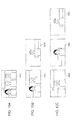
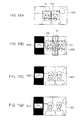
- Figs. 16A to 16F are diagrams illustrating a sixth example.
- a setting of a region to be extracted from a captured image will be described.
- Figs. 16A to 16F are diagrams illustrating a setting of a region to be extracted from a captured image.
- extraction region CA1, CA2, and CA3 are set using a vertical axis VA which passes the center of a face of a user as a reference as shown in Figs. 16A to 16C .
- extraction regions CA4, CA5, and CA6 may be set using the vertical line VA which passes the center of the face of the user and a horizontal axis HA which passes eyes in the face of the user, for example, as references as shown in Figs. 16D to 16F .
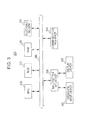
- FIG. 13 is a diagram illustrating the functional configuration of the information processing apparatus of this embodiment.
- An information processing apparatus 250 serving as the information processing apparatus of this embodiment is different from the information processing apparatus of the first embodiment described above only in that the information processing apparatus 250 includes an image pickup unit 252 and a display unit 254. Therefore, descriptions of redundant configurations and operations are omitted, and configurations and operations different from those of the first embodiment will be described hereinafter.
- a user A who uses the information processing apparatus 250, a communication network 800 to which the information processing apparatus 250 is connectable, a communication server 300 and information processing apparatuses 550 and 750 which are connectable to the communication network 800, users B and C who use the information processing apparatus 550, and a user D who uses the information processing apparatus 750 are shown.
- the information processing apparatuses 550 and 750 have the same configuration as the information processing apparatus 250, and therefore, detailed descriptions thereof are omitted.
- the information processing apparatus 250 includes the image pickup unit 252, a detection unit 204, a head-count obtaining unit 206, a setting unit 208, a display image generation unit 210, a communication unit 212, the display unit 254, and a display controller 216.
- the image pickup unit 252 is an example of an image pickup unit and may capture a still image or a moving image of a user A who watches a display screen of the display unit 254. Then, the image pickup unit 252 may transmit a captured image generated through image capturing to the communication unit 212, the detection unit 204, and display image generation unit 210.
- the display unit 254 is an example of a display unit and may display content of a still image or a moving image and captured images supplied from the information processing apparatuses 550 and 750 in parallel.
- the display unit 254 may display content of a still image or a moving image in a display region for content and display captured images supplied from the information processing apparatuses 550 and 750 in a display region for captured images supplied from the information processing apparatuses 550 and 750 in the display screen.
- an object may be achieved by supplying a storage medium, such as a non-transitory storage medium, which stores a program code of software which realizes functions of the foregoing embodiments to a system or an apparatus and reading and executing the program code stored in the storage medium using a computer (or a CPU, an MPU, or the like) of the system or the apparatus.
- a storage medium such as a non-transitory storage medium, which stores a program code of software which realizes functions of the foregoing embodiments to a system or an apparatus and reading and executing the program code stored in the storage medium using a computer (or a CPU, an MPU, or the like) of the system or the apparatus.
- the program code which is read from the storage medium realizes the functions of the foregoing embodiments, and the program code and the storage medium which stores the program code are included.
- examples of the storage medium to which the program code is supplied include a floppy (registered trademark) disk, a hard disk, a magneto-optical disc, an optical disc such as an CD-ROM, a CD-R, a CD-RW, a DVD-ROM, a DVD-RAM, a DVD-RW, or a DVD+RW, a magnetic tape, a nonvolatile memory card, and a ROM.
- the program code may be downloaded through a network.
- the present invention further includes embodiments where an OS (Operating System) operating in a computer performs a part of or entire actual process in accordance with an instruction of the program code and the functions of the foregoing embodiments.
- OS Operating System
- the present invention further includes embodiments where, after the program code read from the storage medium is written to a memory included in a function expansion board inserted into the computer or a function expansion unit connected to the computer, a CPU or the like included in the expansion board or the expansion unit executes a part of or entire actual process in accordance with an instruction of the program code and the functions of the foregoing embodiments are realized by the process.
- the communication server 300 may detect face regions including faces of users who use the information processing apparatuses 500 and 700 in captured images supplied from the information processing apparatuses 500 and 700.
- the information processing apparatus 200 may transmit content desired by the user A to the information processing apparatuses 500 and 700 so that the content is shared by the users.
Abstract
Description
- The present invention relates to an information processing apparatus and an information processing method.
- In general, as devices used for communication between users being in different locations, telephones, so-called videophones, and video conference systems have been used. In addition, text chat and video chat including video images and audio have also been performed through the Internet using personal computers.
- Therefore, electronic devices and like devices have been offering high functionalities and an increasing range of functions. For example, a television receiver includes a network communication function which enables not only reception of video and audio content of a program from a broadcasting station and display of the content but also transmission of various information to and reception of various information from another receiver.
- For example, Japanese Unexamined Patent Application Publication No.
2006-50370 - Here, when display of content and display of an image externally received through network communication (hereinafter referred to as a "communication image") are performed in parallel in a display device such as a television receiver, a PIP (Picture in Picture) display method or a POP (Picture on Picture) display method is generally used.
- However, there arises a problem in that, when the PIP display method or the POP display method is used, a portion of the displayed content is hidden by the displayed communication image, and accordingly, it is difficult to view the content. Furthermore, in general, since a region for displaying the communication image is limited in a display screen, a size of the communication image is reduced in the display screen. Therefore, there arises a problem in that sizes of images of other users included in the communication image become small, and accordingly, it is difficult to identify the users and image quality of the communication image is deteriorated.
- Accordingly, it is desirable to provide an information processing apparatus and an improved information processing method which are capable of appropriately performing display of content and display of a communication image when the content and the communication image are displayed in parallel.
- In accordance with one aspect of the invention, an information processing apparatus may include an obtaining unit to obtain a number of users from information on detection of a face region including a face in a captured image provided at the apparatus. The apparatus also may include a setting unit to set a display region for content and a display region for a captured image in a display screen. Further, the apparatus may include a display image generation unit to generate a display image to be displayed in the display region for a captured image, in accordance with the information on the detection, the number of users, and the display region set for a captured image.
- In accordance with another aspect, of the invention, a method may include obtaining a number of users from information on detection of a face region including a face in a captured image; setting a display region for content and a display region for a captured image in a display screen; and generating a display image to be displayed in the display region for a captured image, in accordance with the information on the detection, the number of users, and the display region set for a captured image. In such method, at least one of the obtaining, the setting and the generating may be by a processor.
- In accordance with another aspect of the invention, a non-transitory recording medium may be recorded with a computer-readable program having instructions executable by a processor. The program may include obtaining a number of users from information on detection of a face region including a face in a captured image; setting a display region for content and a display region for a captured image in a display screen; and generating a display image to be displayed in the display region for a captured image, in accordance with the information on the detection, the number of users, and the display region set for a captured image.
- As described above, display of content and display of a communication image may be appropriately performed in parallel.
-
Fig. 1 is a diagram illustrating a display system according to an embodiment; -
Fig. 2 is a diagram illustrating a functional configuration of an information processing apparatus according to a first embodiment; -
Fig. 3 is a diagram illustrating a hardware configuration of the information processing apparatus shown inFig. 2 ; -
Fig. 4 is a flowchart of a display process executed by the information processing apparatus shown inFig. 2 ; -
Fig. 5 is a flowchart of a parallel display process included in the display process shown inFig. 4 ; -
Fig. 6 is a diagram illustrating an image captured in another display system; -
Figs. 7A to 7D are diagrams illustrating content and captured images supplied from another information processing apparatus which are displayed in parallel in a display screen of a display device; -
Fig. 8A is a diagram illustrating an image captured by another display system when two users are using the display system; -
Fig. 8B is a diagram illustrating images captured by other display systems when each of the display systems is used by a single user; -
Figs. 9A to 9D are diagrams illustrating content and a captured image supplied from another information processing apparatus which are displayed in parallel in the display screen of the display device; -
Fig. 10A is a diagram illustrating an image captured by another display system when three users are using the display system; -
Fig. 10B is a diagram illustrating images captured by other display systems when one of the display systems is used by two users and the other is used by a single user; -
Fig. 10C is a diagram illustrating images captured by other display systems when each of the display systems is used by a single user; -
Figs. 11A to 11D are diagrams illustrating content and a captured image supplied from another information processing apparatus which are displayed in parallel in the display screen of the display device; -
Figs. 12A to 12D are diagrams illustrating content and a captured image supplied from another information processing apparatus which are displayed in parallel in the display screen of the display device; -
Fig. 13 is a diagram illustrating a functional configuration of an information processing apparatus according to a second embodiment; -
Figs. 14A to 14C are diagrams illustrating a fourth embodiment; -
Figs. 15A to 15D are diagrams illustrating a fifth embodiment; and -
Figs. 16A to 16F are diagrams illustrating a sixth embodiment. - Embodiments of the present invention will be described with reference to the accompanying drawings. Note that, in this specification and the drawings, components having substantially the same functions are denoted by the same reference numerals so that redundant descriptions are avoided.
Note that a description will be made in the following order. - 1. Display System
- 2. Functional Configuration of Information Processing Apparatus (First Embodiment)
- 3. Hardware Configuration of Information Processing Apparatus
- 4. Display Process
- 5. Examples
- 6. Functional Configuration of Information Processing Apparatus (Second Embodiment)
- First, a display system according to an embodiment of the present invention will be described.
Fig. 1 is a diagram illustrating a display system according to an embodiment.Fig. 1 is a front view of the display system viewed from the front. - In
Fig. 1 , adisplay system 100 includes adisplay device 102 and animage pickup device 104, for example. - The
display device 102 is an example of a display device, and displays still images or moving images in accordance with driving signals. For example, thedisplay device 102 displays a still image or a moving image using liquid crystal. Note that thedisplay device 102 may display a still image or a moving image using self-luminous display device such as an organic EL (Electroluminescence). - The
image pickup device 104 which is an example of an image pickup device is disposed in an upper center portion of thedisplay device 102 and captures a subject located in a display direction of thedisplay device 102. Theimage pickup device 104 may take still images or moving images using a CCD (Charge Coupled Device) image sensor or may take still images or moving images using a CMOS (Complementary Metal Oxide Semiconductor) image sensor. - Note that, although the
image pickup device 104 is disposed in the upper center portion of thedisplay device 102 in this embodiment, a location where theimage pickup device 104 is disposed is not limited to the upper center portion of thedisplay device 102. For example, theimage pickup device 104 may be disposed in a lower center portion of thedisplay device 102. Furthermore, although the singleimage pickup device 104 is disposed in this embodiment, the number ofimage pickup devices 104 is not limited to one. For example, two or moreimage pickup devices 104 may be disposed. Furthermore, although thedisplay device 102 and theimage pickup device 104 are integrally configured in this embodiment, thedisplay device 102 and theimage pickup device 104 may be separately configured. - Note that the
display system 100 may include a sensor (not shown) which detects presence or absence of a user positioned in front of thedisplay device 102 and a signal reception unit (not shown) capable of receiving a control signal through an infrared communication or a wireless communication from a remote controller (not shown). Furthermore, the sensor may detect a distance between thedisplay device 102 and the user positioned in front of thedisplay device 102. - The
display device 102 of this embodiment may display content corresponding to a still image or a moving image and images captured by otherinformation processing apparatuses Fig. 2 in parallel which will be described hereinafter. For example, thedisplay device 102 may display content corresponding to a still image or a moving image in a content display region in a display screen and display images captured by the otherinformation processing apparatuses information processing apparatuses information processing apparatuses - Furthermore, the
image pickup device 104 of this embodiment may capture a still image and a moving image regarding a user A who is watching the display screen of thedisplay device 102 shown inFig. 2 . - Next, a functional configuration of an information processing apparatus according to a first embodiment will be described.
Fig. 2 is a diagram illustrating a functional configuration of the information processing apparatus according to the first embodiment. Note that,Fig. 2 includes adisplay system 100 which transmits a captured image to aninformation processing apparatus 200 serving as the information processing apparatus according to this embodiment and which receives a signal for driving thedisplay device 102 from theinformation processing apparatus 200 and a user A who uses thedisplay system 100 and theinformation processing apparatus 200. Furthermore,Fig. 2 includes acommunication network 800 to which theinformation processing apparatus 200 is connectable, acommunication server 300 and otherinformation processing apparatuses communication network 800, adisplay system 400 which transmits a captured image to theinformation processing apparatus 500 and which receives a signal from theinformation processing apparatus 500, users B and C who use thedisplay system 400 and theinformation processing apparatus 500, adisplay system 600 which transmits a captured image to theinformation processing apparatus 700 and which receives a signal from theinformation processing apparatus 700, and a user D who uses thedisplay system 600 and theinformation processing apparatus 700. Thedisplay systems display system 100, and therefore, detailed descriptions thereof are omitted. Furthermore, theinformation processing apparatuses information processing apparatus 200, and therefore, detailed descriptions thereof are omitted. Theinformation processing apparatuses - In
Fig. 2 , theinformation processing apparatus 200 includes aninput unit 202, adetection unit 204, a head-count obtaining unit 206, asetting unit 208, a displayimage generation unit 210, acommunication unit 212, anoutput unit 214, and adisplay controller 216. - The
input unit 202 receives a captured image which is generated by theimage pickup device 104 through image capturing. The captured image generated by theimage pickup device 104 through the image capturing is an example of another captured image. Then, theinput unit 202 transmits the received (input) captured image to thecommunication unit 212. Note that theinput unit 202 may transmit the received captured image to thedetection unit 204 and the displayimage generation unit 210. Furthermore, theinput unit 202 accepts an input for a setting of a display ratio of a display region for content to a display region for captured images supplied from theinformation processing apparatuses display device 102 performed by the user A, for example. Note that theinput unit 202 may accept an input for a setting of a display ratio of a display region for content to a display region for captured images supplied from theinformation processing apparatus display device 102 performed by the user A. Then, theinput unit 202 transmits information on the received input for a setting of a display ratio to thesetting unit 208. The display region for captured images supplied from theinformation processing apparatuses - The
detection unit 204 which is an example of a detection unit receives captured images which are supplied from theinformation processing apparatuses communication unit 212 and detects face regions including faces of the users B, C, and D in the received captured images. Then, thedetection unit 204 transmits information on the face regions as results of the detection to the head-count obtaining unit 206 and the displayimage generation unit 210. Note that thedetection unit 204 may receive a captured image supplied from theinput unit 202 and detect a face region including a face of the user A in the received captured image. Then, thedetection unit 204 may transmit information on the face region including the face of the user A as a result of the detection to the head-count obtaining unit 206, the displayimage generation unit 210, and thecommunication unit 212. A technique disclosed in Japanese Unexamined Patent Application Publication No.2007-65766 2005-44330 detection unit 204. Hereinafter, the detection of a face region will be briefly described. - To detect the face of the user A in the captured image, for example, a face position, a face size, and a face direction are individually detected in the received captured image. When the face position and the face size are detected, a portion corresponding to a face image may be extracted from the image. Then, in accordance with the extracted face image and information on the face direction, characteristic portions of the face (face feature positions) such as eye blows, eyes, a nose, and a mouth are detected. A method referred to as an AAM (Active Appearance Models) method, for example, may be used for the detection of the face feature positions.
- After the face feature positions are detected, local feature values of the detected face feature positions are individually calculated. When the local feature values are calculated and the calculated local feature values are stored along with the face image, a face is identified in the image captured by the
image pickup device 104. A technique disclosed in Japanese Unexamined Patent Application Publication No.2007-65766 2005-44330 - The head-
count obtaining unit 206 which is an example of an obtaining unit receives information on the face regions including the faces of the users B, C, and D detected by thedetection unit 204. Then, the head-count obtaining unit 206 obtains the number of users who use theinformation processing apparatuses count obtaining unit 206 transmits a result of the obtainment of the number of users who use theinformation processing apparatuses image generation unit 210. Note that the head-count obtaining unit 206 may receive information on a face region including the face of the user A detected by thedetection unit 204 and obtain the number of users who use theinformation processing apparatus 200 in accordance with received information on the face region including the face of the user A. Then, the head-count obtaining unit 206 may transmit a result of the obtainment of the number of users who use theinformation processing apparatus 200 to the displayimage generation unit 210 and thedisplay controller 216. Furthermore, when thecommunication unit 212 receives the information on the face regions including the faces of the users B and C detected in the image captured using thedisplay system 400 and information on the face region including the face of the user D detected in the image captured using thedisplay system 600, the head-count obtaining unit 206 may receive the information on the face regions and obtain the number of users who use theinformation processing apparatuses detection unit 204 described above may not detect the face regions including the faces of the users B, C and D in the captured images supplied from theinformation processing apparatuses - The
setting unit 208 which is an example of a setting unit receives information on the input for the setting of the display ratio from theinput unit 202 and sets the display region for content and a display region for captured images supplied from theinformation processing apparatuses display device 102 in accordance with the received information on the input for the setting of the display ratio. Furthermore, thesetting unit 208 may set a display region for content and a display region for captured images supplied from theinformation processing apparatuses display device 102 in accordance with the received information on the input for the setting of the display ratio. Then, thesetting unit 208 transmits information on the set display region for captured images to the displayimage generation unit 210 and thedisplay controller 216 and transmits information on the set display region for content to thedisplay controller 216. For example, thesetting unit 208 sets a size of the display region for content and a size of the display region for captured images supplied from theinformation processing apparatuses display device 102 and transmits information on the set size of the display region for content and information on the set size of the display region for captured images. - The display
image generation unit 210 which is an example of a generation unit receives information on the face regions including the faces of the users B, C, and D from thedetection unit 204, receives the result of the obtainment of the number of users who use theinformation processing apparatuses count obtaining unit 206, receives the information on the display region for captured images supplied from theinformation processing apparatuses setting unit 208, and receives the image captured using thedisplay system 400 and the image captured using thedisplay system 600 which are received by thecommunication unit 212. Then, in accordance with the received information on the face regions including the faces of the users B, and C and D, the received result of the obtainment of the number of users who use theinformation processing apparatuses information processing apparatuses image generation unit 210 generates a display image to be displayed in the display region for captured images supplied from theinformation processing apparatuses display device 102 using the image captured by thedisplay system 400 and the image captured by thedisplay system 600. Thereafter, the displayimage generation unit 210 transmits the generated display image to thedisplay controller 216. - For example, the display
image generation unit 210 extracts a portion of the image captured by thedisplay system 400 corresponding to one third of the display region for captured images such that at least face feature portions of the user B are included in the portion in accordance with the information on the face region including the face of the user B, the result of the obtainment of the number of users who use theinformation processing apparatuses information processing apparatuses image generation unit 210 extracts a portion of the image captured by thedisplay system 400 corresponding to one third of the display region for captured images such that at least face feature portions of the user C are included in the portion in accordance with the information on the face region including the face of the user C, the information representing that the number of users who use theinformation processing apparatuses information processing apparatuses image generation unit 210 extracts a portion of the image captured by thedisplay system 600 corresponding to one third of the display region for captured images such that at least face feature portions of the user D are included in the portion in accordance with the information on the face region including the face of the user D, the information representing that the number of users who use theinformation processing apparatuses information processing apparatuses image generation unit 210 arranges the extracted captured images in the display region for captured images supplied from theinformation processing apparatuses display device 102 such that the faces of the users who use theinformation processing apparatuses - When receiving the image captured by the display system 100 from the input unit 202, receiving the information on the face region including the face of the user A and the information on the face regions including the faces of the users B, C, and D from the detection unit 204, receiving the result of the obtainment of the number of users who use the information processing apparatus 200 and the result of the obtainment of the number of users who use the information processing apparatuses 500 and 700 from the head-count obtaining unit 206, receiving the information on the display regions for captured images of the information processing apparatuses 200, 500, and 700 from the setting unit 208, and receiving the image captured by the display system 400 and the image captured by the display system 600 which are received by the communication unit 212, the display image generation unit 210 may generate a display image to be displayed in the display region for captured images supplied from the information processing apparatuses 200, 500, and 700 included in the display screen of the display device 102 using the image captured by the display system 100, the image captured by the display system 400, and the image captured by the display system 600 in accordance with the received information on the face region including the face of the user A, the received information on the face region including the faces of the users B and C, the received information on the face region including the face of the user D, the received result of the obtainment of the number of users who use the information processing apparatus 200, the received result of the obtainment of the number of users who use the information processing apparatuses 500 and 700, and the information on the display region for captured images supplied from the information processing apparatuses 200, 500, and 700.
- In this case, the display
image generation unit 210 extracts a portion of the image captured by thedisplay system 100 corresponding to a quarter of the display region for captured images such that at least face feature portions of the user A are included in the portion in accordance with the information on the face region including the face of the user A, the result of the obtainment of the number of users who use theinformation processing apparatuses information processing apparatuses image generation unit 210 extracts a portion of the image captured by thedisplay system 400 corresponding to a quarter of the display region for captured images such that at least face feature portions of the user B are included in the portion in accordance with the information on the face region including the face of the user B, the information representing that the number of users who use theinformation processing apparatuses information processing apparatuses image generation unit 210 extracts a portion of the image captured by thedisplay system 400 corresponding to a quarter of the display region for captured images such that at least face feature portions of the user C are included in the portion in accordance with the information on the face region including the face of the user C, the information representing that the number of users who use theinformation processing apparatuses information processing apparatuses image generation unit 210 extracts a portion of the image captured by thedisplay system 600 corresponding to a quarter of the display region for captured images such that at least face feature portions of the user D are included in the portion in accordance with the information on the face region including the face of the user D, the information representing that the number of users who use theinformation processing apparatuses information processing apparatuses image generation unit 210 arranges the extracted captured images in the display region for captured images supplied from theinformation processing apparatuses display device 102 such that the faces of the users who use theinformation processing apparatuses - Note that, when the
communication unit 212 receives the information on the face regions including the faces of the users B and C detected in the image captured by thedisplay system 400 or the information on the face region including the face of the user D detected in the image captured by thedisplay system 600, the displayimage generation unit 210 may receive the information on the face images and generate a display image in accordance with the information on the face regions received by thecommunication unit 212 instead of the information on the face regions detected by thedetection unit 204. - Furthermore, the display
image generation unit 210 may extract portions of the captured images such that invalid regions which are wasted regions are not included in the display image in accordance with the received information on the face regions to thereby generate the display image. Moreover, the displayimage generation unit 210 may extract portions of the captured images such that the same portions which display the same images are not included in the display image to thereby generate the display image. In addition, the displayimage generation unit 210 may generate a display image regarding a plurality of users as a single user when the users are positioned near one another in a captured image in accordance with received information on face regions. - The
communication unit 212 which is an example of a reception unit receives an image captured using thedisplay system 400 from thecommunication server 300 through thecommunication network 800. Furthermore, thecommunication unit 212 receives an image captured by thedisplay system 600 from thecommunication server 300 through thecommunication network 800. Note that thecommunication unit 212 may directly receive an image captured by thedisplay system 400 from theinformation processing apparatus 500 through thecommunication network 800. Similarly, thecommunication unit 212 may directly receive an image captured by thedisplay system 600 from theinformation processing apparatus 700 through thecommunication network 800. - Moreover, the
communication unit 212 may receive a captured image supplied from theinput unit 202 and transmit the received captured image to thecommunication server 300 through thecommunication network 800. Furthermore, thecommunication unit 212 may receive the information on the face region including the user A detected in the image captured using thedisplay system 100 by thedetection unit 204 and transmit the received information on the face region to thecommunication server 300 through thecommunication network 800. Note that thecommunication unit 212 may directly transmit the received captured image and the information on the face region to theinformation processing apparatuses communication network 800. - Furthermore, the
communication unit 212 may receive the information on the face regions including the faces of the users B and C detected in the image captured using thedisplay system 400 and the information on the face region including the face of the user D detected in the image captured using thedisplay system 600 from thecommunication server 300 through thecommunication network 800. Note that thecommunication unit 212 may directly receive the information on the face regions including the faces of the users B and C detected in the image captured using thedisplay system 400 from theinformation processing apparatus 500 through thecommunication network 800. Similarly, thecommunication unit 212 may directly receive the information on the face region including the face of the user D detected in the image captured using thedisplay system 600 from theinformation processing apparatus 700 through thecommunication network 800. - The
output unit 214 receives a signal used to drive thedisplay device 102 from thedisplay controller 216 and transmits the received signal to thedisplay device 102. - The
display controller 216 which is an example of a controller receives information on the display region for content from thesetting unit 208 and the information on the display region for captured images supplied from theinformation processing apparatuses display controller 216 receives content corresponding to a still image or a moving image. Then, thedisplay controller 216 transmits a signal for displaying the display image generated by the displayimage generation unit 210 in the display region for captured images supplied from theinformation processing apparatuses display device 102 to theoutput unit 214. Moreover, thedisplay controller 216 transmits a signal for displaying content having a reduced image size in the display region for content in the display screen of thedisplay device 102 to theoutput unit 214. - Note that, when receiving the information on the display region for content and the information on the display region for captured images supplied from the information processing apparatuses, 200, 500, and 700 from the
setting unit 208 and receiving the display image from the displayimage generation unit 210, thedisplay controller 216 may transmit to the output unit 214 a signal for displaying the display image generated by the displayimage generation unit 210 in the display region for captured images supplied from theinformation processing apparatuses display device 102. - Next, a hardware configuration of the
information processing apparatus 200 shown inFig. 2 will be described.Fig. 3 is a diagram illustrating a hardware configuration of theinformation processing apparatus 200 shown inFig. 2 . - In
Fig. 3 , theinformation processing apparatus 200 includes anMPU 230, aROM 232, aRAM 234, arecording medium 236, an input/output interface 238, anoperation input device 240, adisplay device 242, and acommunication interface 244. Furthermore, in theinformation processing apparatus 200, the components are connected to one another through abus 246 serving as a data transmission path. - The
MPU 230 includes an MPU (Micro Processing Unit) and an integrated circuit in which a plurality of circuits are integrated to realize various functions such as image processing and functions as a controller (not shown) which controls the entireinformation processing apparatus 200. Furthermore, in theinformation processing apparatus 200, theMPU 230 functions as thedetection unit 204, the head-count obtaining unit 206, thesetting unit 208, the displayimage generation unit 210, and thedisplay controller 216. - The
ROM 232 stores programs and control data such as calculation parameters used by theMPU 230. TheRAM 234 temporarily stores programs executed by theMPU 230, for example. - The
recording medium 236 stores applications, for example. Here, examples of therecording medium 236 include a magnetic recording medium such as a hard disk and a nonvolatile memory such as an EEPROM (Electrically Erasable and Programmable Read Only Memory), a flash memory, an MRAM (Magnetoresistive Random Access Memory), an FeRAM (Ferroelectric Random Access Memory), or a PRAM (Phase change Random Access Memory). Furthermore, theinformation processing apparatus 200 may include arecording medium 236 which is detachable from theinformation processing apparatus 200. - The input/
output interface 238 is connected to theoperation input device 240 and thedisplay device 242, for example. Furthermore, the input/output interface 238 functions as theinput unit 202 and theoutput unit 214. Theoperation input device 240 functions as an operation unit (not shown), and thedisplay device 242 functions as adisplay unit 254 which will be described with reference toFig. 13 . Here, examples of the input/output interface 238 include a USB (Universal Serial Bus) terminal, a DVI (Digital Visual Interface) terminal, an HDMI (High-Definition Multimedia Interface) terminal, and various processing circuits. Furthermore, theoperation input device 240 is disposed on theinformation processing apparatus 200, for example, and is connected to the input/output interface 238 inside theinformation processing apparatus 200. Examples of theoperation input device 240 include a button, a direction key, a rotatable selector such as a jog dial, and a combination thereof. Furthermore, thedisplay device 242 is disposed on theinformation processing apparatus 200, for example, and is connected to the input/output interface 238 inside theinformation processing apparatus 200. Examples of thedisplay device 242 include an LCD (Liquid Crystal Display) and an organic EL (ElectroLuminescence) display (which is also referred to as an OLED (Organic Light Emitting Diode) display). Note that it is apparent that the input/output interface 238 may be connected to an operation input device (for example, a keyboard and a mouse) serving as an external apparatus of theinformation processing apparatus 200 and an external device such as a display device (for example, an external display device such as the display device 102) and an image pickup device (for example, the image pickup device 104). Furthermore, thedisplay device 242 may be a device which is capable of performing display and which allows a user's operation, such as a touch screen. - The
communication interface 244 which is a communication unit included in theinformation processing apparatus 200 functions as thecommunication unit 212 which performs communication with an external apparatuses including theserver 300 and theinformation processing apparatuses communication interface 244 include a combination of a communication antenna and an RF circuit (wireless communication), a combination of an IEEE802.15.1 port and a transmission/reception circuit (wireless communication), a combination of an IEEE802.11b port and a transmission/reception circuit (wireless communication), and a combination of a LAN terminal and a transmission/reception circuit (wired communication). - Note that the hardware configuration of the
information processing apparatus 200 according to this embodiment is not limited to the configuration shown inFig. 3 . For example, theinformation processing apparatus 200 may include an audio output device which serves as an audio output unit (not shown) and which includes a DSP (Digital Signal Processor), an amplifier, and a speaker. - Furthermore, the
information processing apparatus 200 may include an image pickup device which serves as animage pickup unit 252 shown inFig. 13 and which includes a lens-and-image pickup element, and a signal processing circuit. In this case, theinformation processing apparatus 200 may process a captured image generated by itself. Here, the lens-and-image pickup element includes an optical lens and an image sensor including a plurality of image pickup elements such as CCD (Charge Coupled Device) sensors or CMOS (Complementary Metal Oxide Semiconductor) sensors. The signal processing circuit which includes an AGC (Automatic Gain Control) circuit and an ADC (Analog to Digital Converter) converts analog signals generated by the image pickup elements into digital signals (image data) and performs various signal processes. Examples of the signal processes performed by the signal processing circuit include a White Balance correction process, an interpolation process, a tone correction process, a gamma correction process, an YCbCr conversion process, an edge emphasizing process, and a coating process. - Moreover, the
information processing apparatus 200 may not include theoperation input device 240 and thedisplay device 242 shown inFig. 3 , for example. - Next, a display process executed by the
information processing apparatus 200 shown inFig. 2 will be described.Fig. 4 is a flowchart of the display process executed by theinformation processing apparatus 200 shown inFig. 2 . - In
Fig. 4 , first, when the user A inputs an instruction for displaying content desired by the user A in thedisplay device 102 using theinformation processing apparatus 200, thedisplay controller 216 transmits a signal for displaying the content desired by the user A in the display screen of thedisplay device 102 to theoutput unit 214 which transmits the received signal to thedisplay device 102. By this, the content desired by the user A is displayed in the display screen of the display device 102 (step S100). - Next, when the user A inputs an instruction for connection to the users B, C, and D through the network using the
information processing apparatus 200, thecommunication unit 212 enters a state in which thecommunication unit 212 may communicate with thecommunication server 300 through the communication network 800 (in step S102). Note that, in step S102, thecommunication unit 212 may enter a state in which thecommunication unit 212 may directly communicate with theinformation processing apparatuses communication network 800. - Next, the
communication unit 212 transmits a captured image which is generated through image capturing performed by theimage pickup device 104 included in thedisplay system 100 and which is received through theinput unit 202 to thecommunication server 300 through the communication network 800 (in step S104). Note that, in step S104, thecommunication unit 212 may transmit information on a face region including the face of the user A transmitted from thedetection unit 204 to thecommunication server 300 through thecommunication network 800. Furthermore, in step S104, thecommunication unit 212 may directly transmit the captured image or the information on the face region to theinformation processing apparatuses communication network 800. - Subsequently, the
communication unit 212 receives an image which is captured by thedisplay system 400 and which is transmitted from theinformation processing apparatus 500 through thecommunication server 300. Furthermore, thecommunication unit 212 receives an image which is captured by thedisplay system 600 and which is transmitted from theinformation processing apparatus 700 through the communication server 300 (in step S106). Note that, in step S106, the information on the face regions including the faces of the users B and C detected in the image which is captured by thedisplay system 400 and which is transmitted from theinformation processing apparatus 500 and the information on the face region including the face of the user D detected in the image which is captured by thedisplay system 600 and which is transmitted from theinformation processing apparatus 700 may be received from thecommunication server 300. Furthermore, in step S106, thecommunication unit 212 may directly receive the captured images and the information on the face regions from theinformation processing apparatuses communication network 800. - Subsequently, the
information processing apparatus 200 executes a parallel display process which will be described with reference toFig. 5 (in step S108) so that the content desired by the user A and the captured images supplied from theinformation processing apparatuses display device 102, and thereafter, the process is terminated. -
Fig. 5 is a flowchart of the parallel display process performed in step S108 included in the display process shown inFig. 4 . - In
Fig. 5 , first, the head-count obtaining unit 206 obtains the number of users who use theinformation processing apparatuses count obtaining unit 206 may obtain the number of users who use theinformation processing apparatus 200 in accordance with the information on the face region including the face of the user A detected by thedetection unit 204. Furthermore, in step S200, when thecommunication unit 212 receives the information on the face regions including the faces of the users B and C detected in the image captured by thedisplay system 400 and the information on the face region including the face of the user D detected in the image captured by thedisplay system 600, the number of users who use theinformation processing apparatuses - Next, the
setting unit 208 sets a display region for content and a display region for captured images supplied from theinformation processing apparatuses display device 102 in accordance with information on an input performed by the user A to set the display ratio of the display region for content to the display region for captured images supplied from theinformation processing apparatuses setting unit 208 may set the display region for content and the display region for captured images supplied from theinformation processing apparatuses display device 102 in accordance with the information on an input performed by the user to set the display ratio of the display region for content to the display region for captured images supplied from theinformation processing apparatuses display device 102. - Subsequently, the display
image generation unit 210 extracts portions of the image which is captured by thedisplay system 400 and which is received by thecommunication unit 212 and a portion of the image which is captured by thedisplay system 600 and which is received by thecommunication unit 212 in accordance with the information on the face regions including the faces of the users B, C, and D transmitted from thedetection unit 204, a result of the obtainment of the number of users who use theinformation processing apparatuses count obtaining unit 206, and the information on the display region for captured images supplied from theinformation processing apparatuses information processing apparatuses - Note that, in step S204 and step S206, the display
image generation unit 210 may extract a portion of the image which is captured by thedisplay system 100, portions of the image captured by thedisplay system 400, and a portion of the image captured by thedisplay system 600 in accordance with the information on the face region including the face of the user A transmitted from thedetection unit 204, the information on the face regions including the faces of the users B, C, and D transmitted from thedetection unit 204, a result of the obtainment of the number of users who use theinformation processing apparatus 200 which is supplied from the head-count obtaining unit 206, a result of the obtainment of the number of users who use theinformation processing apparatuses count obtaining unit 206, and the information on the display region for captured images supplied from theinformation processing apparatuses setting unit 208, and generate a display image to be displayed in the display region for captured images supplied from theinformation processing apparatuses display device 102. - Furthermore, in step S204 and step S206, when the
communication unit 212 receives the information on the face regions including the faces of the users B and C detected in the image captured by thedisplay system 400 and the information on the face region including the face of the user D detected by in the image captured by thedisplay system 600, the displayimage generation unit 210 may generate a display image in accordance with the information on the face regions supplied from thecommunication unit 212 instead of the information on the face regions detected by thedetection unit 204. - Next, the
display controller 216 transmits a signal for displaying the content which is desired by the user A and which has a reduced size in the display region for content included in the display screen of thedisplay device 102 to theoutput unit 214 in accordance with the information on the display region for content supplied from thesetting unit 208. By this, the content desired by the user A which corresponds to the image having the reduced size is displayed in the display region for content in the display screen of the display device 102 (in step S208). - Next, the
display controller 216 transmits a signal for displaying the display image generated by the displayimage generation unit 210 in the display region for captured images supplied from theinformation processing apparatuses display device 102 to theoutput unit 214 in accordance with the information on the display region for the captured images supplied from theinformation processing apparatuses setting unit 208. By this, in the display screen of thedisplay device 102, the display image generated by the displayimage generation unit 210 is displayed in the display region for captured images, and accordingly, the content desired by the user A and the captured images supplied from theinformation processing apparatuses - Note that, in step S210, the
display controller 216 may transmit a signal for displaying the display image generated by the displayimage generation unit 210 in the display region for captured images supplied from theinformation processing apparatuses display device 102 to theoutput unit 214 in accordance with the information on the display region for captured images supplied from theinformation processing apparatuses setting unit 208. In this case, in the display screen of thedisplay device 102, the display image generated by the displayimage generation unit 210 is displayed in the display region for captured image, and accordingly, the content desired by the user A and the captured images supplied from theinformation processing apparatuses - According to the display process shown in
Fig. 4 , in the display screen of thedisplay device 102, the display image generated by the displayimage generation unit 210 is displayed in the display region for captured images, and the content desired by the user A which corresponds to the image having the reduced size is displayed in the display region for content. The display image to be displayed in the display region for captured image is generated by extracting portions of the captured images in accordance with the information on the face regions, the result of the obtainment of the number of users, and the information on the display region for captured images such as information on a size of the display region. Therefore, when the size of the display region for captured images is small, the display image to be displayed in the display region for captured images is obtained by removing portions in the captured images which are wasted portions to identify the users, that is, obtained by removing large portions of backgrounds of the captured images, for example. Therefore, since portions of the captured images which are significant portions to identify the users such as portions of the captured images including face feature portions of the users are displayed in the display region for captured images even when the size of the display region for captured images is small, it is not difficult to identify the users. Furthermore, image quality of the display image is not deteriorated. Furthermore, since the image size of the content to be displayed in the content display region is reduced, it is unlikely that a portion of the content is hidden due to the display of the display image. Accordingly, the display of the content and the display of the captured images are appropriately performed in parallel. - Next, examples will be described.
Fig. 6 andFigs. 7A to 7D are diagrams for explanation of a first example. In the first example, a case where content desired by a user who uses thedisplay system 100 and an image captured by thedisplay system 400 are displayed in parallel in the display screen of thedisplay device 102 shown inFig. 2 will be described. Note that, in this first example, a case where a single user uses thedisplay system 400 will be described. -
Fig. 6 is a diagram illustrating an image captured by thedisplay system 400. InFig. 6 , an image IM1 captured by thedisplay system 400 is transmitted to thedetection unit 204 included in theinformation processing apparatus 200 as described above, and thedetection unit 204 detects a face region FA1 including a face of the user who uses thedisplay system 400. -
Figs. 7A to 7D are diagrams illustrating content and a captured image supplied from theinformation processing apparatus 500 which are displayed in parallel in the display screen of thedisplay device 102. -
Fig. 7A shows a case where a display ratio of a display region for content to a display region for captured images supplied from theinformation processing apparatus 500 which is obtained through an input for setting of the display ratio of the display region for content to the display region for captured images isA1:B1 (B1=0).Fig. 7B shows a case where a display ratio of the display region for content to the display region for captured images is A2:B2 (B2 < A2).Fig. 7C shows a case where a display ratio of the display region for content to the display region for captured images is A3:B3 (B3 = A3).Fig. 7D shows a case where a display ratio of the display region for content to the display region for captured images is A4:B4 (A4 = 0). - As shown in
Figs. 7B and 7C , in the display screen of thedisplay device 102, a display image IM2 or IM4 which is generated by extracting a portion of the image IM1 is displayed in the display region for captured images and content IM3 or IM5 which is desired by the user who uses thedisplay system 100 and which corresponds to an image having a reduced size is displayed in the display region for content. By this, the user who uses thedisplay system 100 may view the content IM3 or IM5 which is not partially hidden and easily identify the user who uses thedisplay system 400 and whose face is included in the captured image. -
Fig. 8A andFigs. 9A to 9D are diagrams illustrating a second example. In the second example, a case where content desired by a user who uses thedisplay system 100 and an image captured by thedisplay system 400 are displayed in parallel in the display screen of thedisplay device 102 shown inFig. 2 will be described. Note that, in the second example, a case where two users use thedisplay system 400 will be described. -
Fig. 8A is a diagram illustrating an image captured by thedisplay system 400 when two users use thedisplay system 400. InFig. 8A , an image IM6 captured by thedisplay system 400 is supplied to thedetection unit 204 included in theinformation processing apparatus 200 as described above, and thedetection unit 204 detects face regions FA2 and FA3 individually including faces of the two users who use thedisplay system 400. -
Figs. 9A to 9D are diagrams illustrating content and a captured image supplied from theinformation processing apparatus 500 which are displayed in parallel in the display screen of thedisplay device 102. -
Fig. 9A shows a case where a display ratio of the display region for content to the display region for captured images supplied from theinformation processing apparatus 500 which is obtained through an input for setting of the display ratio of the display region for content to the display region for captured images is A5:B5 (B5=0).Fig. 9B shows a case where a display ratio of the display region for content to the display region for captured images is A6:B6 (B6 < A6).Fig. 9C shows a case where a display ratio of the display region for content to the display region for captured images is A7:87 (B7 = A7).Fig. 9D shows a case where a display ratio of the display region for content to the display region for captured images is A8:B8 (A8 = 0). - As shown in
Figs. 9B and 9C , in the display screen of thedisplay device 102, a display image IM9 or IM11 which is generated by extracting a portion of the image IM6 is displayed in the display region for captured images and content IM10 or IM12 which is desired by the user who uses thedisplay system 100 and which corresponds to an image having a reduced size is displayed in the display region for content. By this, the user who uses thedisplay system 100 may view the content IM10 or IM12 which is not partially hidden and easily identify the two users who use thedisplay system 400 and whose faces are included in the captured image. - Note that, as shown in
Fig. 8B , also in a case where, when a single user uses thedisplay system 400 and a single user uses thedisplay system 600, the content desired by the user who uses thedisplay system 100 and images IM7 and IM8 captured by thedisplay systems display systems display device 102 as shown inFigs. 9A to 9D (specifically,Figs. 9B and 9C ). -
Fig. 10A andFigs. 11A to 11D are diagrams illustrating a third example. Note that frames representing face regions are omitted inFig. 10A and the following drawings. In the third example, a case where content desired by a user who uses thedisplay system 100 and an image captured by thedisplay system 400 are displayed in parallel in the display screen of thedisplay device 102 shown inFig. 2 will be described. Note that a case where three users use thedisplay system 400 will be described in the third example. -
Fig. 10A is a diagram illustrating an image captured by thedisplay system 400 when three users use thedisplay system 400. InFig. 10A , an image IM13 captured by thedisplay system 400 is transmitted to thedetection unit 204 included in theinformation processing apparatus 200 as described above, and thedetection unit 204 detects face regions (not shown) individually including faces of the three users who use thedisplay system 400. -
Figs. 11A to 11D are diagrams illustrating the content and an image captured by theinformation processing apparatus 500 which are displayed in parallel in the display screen of thedisplay device 102. -
Fig. 11A shows a case where a display ratio of a display region for content to a display region for captured images supplied from theinformation processing apparatus 500 which is obtained through an input for setting of the display ratio of the display region for content to the display region for captured images is A9:B9 (B9=0).Fig. 11B shows a case where a display ratio of the display region for content to the display region for captured images is A10:B10 (B10 <A10).Fig. 11C shows a case where a display ratio of the display region for content to the display region for captured images is A11:B11 (B11 =A11).Fig. 11D shows a case where a display ratio of the display region for content to the display region for captured images is A12:B12 (A12 = 0). - As shown in
Figs. 11B and 11C , in the display screen of thedisplay device 102, a display image IM19 or IM21 which is generated by extracting a portion of the image IM13 is displayed in the display region for captured images and content IM20 or IM22 which is desired by the user who uses thedisplay system 100 and which corresponds to an image having a reduced size is displayed in the display region for content. By this, the user who uses thedisplay system 100 may view the content IM20 or IM22 which is not partially hidden and easily identify the three users who use thedisplay system 400 and whose faces are included in the captured image. - Note that, even in a case where two users use the
display system 400 and a single user uses thedisplay system 600 as shown inFig. 10B , the content desired by the user who uses thedisplay system 100 and images IM14 and IM15 captured by thedisplay systems display device 102 as shown inFigs. 11A to 11D (specifically,Figs. 11B and 11C ). Similarly, even in a case where a single user uses thedisplay system 400, a single user uses thedisplay system 600, and a single user uses another display system (not shown) as shown inFig. 10C , the content desired by the user who uses thedisplay system 100 and images IM16, IM17, IM18 captured by thedisplay systems display device 102 as shown inFigs. 11A to 11D (specifically,Figs. 11B and 11C ). - Furthermore, similarly, as shown in
Figs. 12A to 12D (specifically,Figs. 12B and 12C ), even when four users use thedisplay system 400 and other systems, the content desired by the user who use thedisplay system 100 and images (not shown) captured by thedisplay system 400 and the other systems may be displayed in parallel in the display screen included in thedisplay device 102. -
Figs. 14A to 14C are diagrams illustrating a fourth example. In the fourth example, a case where content desired by the user who uses thedisplay system 100 and an image captured by thedisplay system 400 are displayed in parallel in the display screen of thedisplay device 102 shown inFig. 2 will be described. Note that, in the fourth example, a case where a single user uses thedisplay system 400 and the user is included in an end portion of an image captured by thedisplay system 400 will be described. -
Fig. 14A is a diagram illustrating the image captured by thedisplay system 400. InFig. 14A , an image IM23 captured by thedisplay system 400 is transmitted to thedetection unit 204 included in theinformation processing apparatus 200 as described above, and thedetection unit 204 detects a face region FA4 including a face of the user who uses thedisplay system 400. -
Figs. 14B and 14C are diagrams illustrating the content and the captured image supplied from theinformation processing apparatus 500 which are displayed in parallel in the display screen included in thedisplay device 102. - As shown in
Fig. 14B , a display image IM24 generated by extracting a portion of the captured image IM23 is displayed in a display region for captured images and content IM25 which is desired by the user who uses thedisplay system 100 and which has a reduced image size is displayed in a display region for content. - As shown in
Fig. 14B , when the user is included in the end portion of the captured image and the display image IM 24 is generated by extracting a portion of the captured image IM23 including the face region FA4 as a center, the display image IM 24 displayed in the display region for captured images includes an invalid region R1 which is a wasted region. - Therefore, in the fourth example, when the user is include in the end portion of the captured image, the portion of the captured image IM23 is extracted so that the invalid region R1 is not displayed in the display region for captured images whereby a display image IM26 is generated. For example, when the user is included in a right end portion of the captured image as shown in
Fig. 14A , a portion of the captured image IM23 is extracted using a right edge of the captured image IM23 as a reference so that the display image IM26 is generated. In this case, as shown inFig. 14C , the display image IM26 which does not include the invalid region R1 is displayed in the display region for captured images and content IM27 which is desired by the user who uses thedisplay system 100 and which has a reduced image size is displayed in the display region for content in the display screen of thedisplay device 102. Accordingly, the user who uses thedisplay system 100 may be prevented from having a feeling of strangeness and a discomfort feeling. -
Figs. 15A to 15D are diagrams illustrating a fifth example. In the fifth example, a case where content desired by the user who uses thedisplay system 100 and an image captured by thedisplay system 400 are displayed in parallel in the display screen of thedisplay device 102 shown inFig. 2 will be described. Note that, in the fifth example, a case where two users use thedisplay system 400 and the two users are positioned close to each other in an image captured by thedisplay system 400 will be described. -
Fig. 15A is a diagram illustrating an image captured by thedisplay system 400 when two users use thedisplay system 400. InFig. 15A , an image IM28 captured by thedisplay system 400 is transmitted to thedetection unit 204 included in theinformation processing apparatus 200 as described above, and thedetection unit 204 detects face regions FA5 and FA6 individually including faces of the two users who use thedisplay system 400. -
Figs. 15B to 15D are diagrams illustrating the content and the captured image supplied from theinformation processing apparatus 500 which are displayed in parallel in the display screen of thedisplay device 102. - As shown in
Fig. 15B , in the display screen of thedisplay device 102, a display image IM29 generated by extracting portions of the captured image IM28 is displayed in a display region for captured images and content IM30 which is desired by the user who uses thedisplay system 100 and which has a reduced image size is displayed in a display region for content. - As shown in
Fig. 15B , in a case where the two users are positioned close to each other in the captured image, when the display image IM29 is generated by extracting portions of the captured image IM28 using the face regions FA5 and FA6 as centers, the display image IM29 includes an overlapping region R2 which includes the same images in the display region for captured images. - Therefore, in the fifth example, when the two users are positioned close to each other in the captured image, a display image IM31 is generated by extracting portions of the captured images IM28 such that the overlapping region R2 is not displayed in the display region for captured images. In this case, as shown in
Fig. 15C , the display image IM31 which does not include the overlapping region R2 is displayed in the display region for captured images and content IM32 which is desired by the user who uses thedisplay system 100 and which has a reduced image size is displayed in the display region for content in the display screen of thedisplay device 102. Accordingly, the user who uses thedisplay system 100 may be prevented from having a feeling of strangeness and a discomfort feeling. - Furthermore, in the fifth example, when the two users are positioned close to each other in the captured image, it may be determined that a single user uses the
display system 400 and a display image IM33 may be generated by extracting a portion of the captured image IM28 so that at least face feature portions of the two users are included in the display image IM33. Also in this case, as shown inFig. 15D , the display image IM33 which does not include the overlapping region R2 is displayed in the display region for captured images and content IM34 which is desired by the user who uses thedisplay system 100 and which has a reduced image size is displayed in the display region for content in the display screen of thedisplay device 102. The display image IM31 shown inFig. 15C is generated by arranging two images, and on the other hand, the display image IM33 shown inFig. 15D is a single image, that is, an image generated by integrating the two images. Accordingly, the user who uses thedisplay system 100 may be prevented from having a feeling of strangeness and a discomfort feeling. -
Figs. 16A to 16F are diagrams illustrating a sixth example. In the sixth example, a setting of a region to be extracted from a captured image will be described.Figs. 16A to 16F are diagrams illustrating a setting of a region to be extracted from a captured image. - In the sixth example, in a captured image IM35, extraction region CA1, CA2, and CA3 are set using a vertical axis VA which passes the center of a face of a user as a reference as shown in
Figs. 16A to 16C . - Furthermore, in the sixth example, in the captured image IM35, extraction regions CA4, CA5, and CA6 may be set using the vertical line VA which passes the center of the face of the user and a horizontal axis HA which passes eyes in the face of the user, for example, as references as shown in
Figs. 16D to 16F . - A functional configuration of an information processing apparatus according to a second embodiment will now be described.
Fig. 13 is a diagram illustrating the functional configuration of the information processing apparatus of this embodiment. Aninformation processing apparatus 250 serving as the information processing apparatus of this embodiment is different from the information processing apparatus of the first embodiment described above only in that theinformation processing apparatus 250 includes animage pickup unit 252 and adisplay unit 254. Therefore, descriptions of redundant configurations and operations are omitted, and configurations and operations different from those of the first embodiment will be described hereinafter. - Note that, in
Fig. 13 , a user A who uses theinformation processing apparatus 250, acommunication network 800 to which theinformation processing apparatus 250 is connectable, acommunication server 300 andinformation processing apparatuses communication network 800, users B and C who use theinformation processing apparatus 550, and a user D who uses theinformation processing apparatus 750 are shown. Theinformation processing apparatuses information processing apparatus 250, and therefore, detailed descriptions thereof are omitted. - In
Fig. 13 , theinformation processing apparatus 250 includes theimage pickup unit 252, adetection unit 204, a head-count obtaining unit 206, asetting unit 208, a displayimage generation unit 210, acommunication unit 212, thedisplay unit 254, and adisplay controller 216. - The
image pickup unit 252 is an example of an image pickup unit and may capture a still image or a moving image of a user A who watches a display screen of thedisplay unit 254. Then, theimage pickup unit 252 may transmit a captured image generated through image capturing to thecommunication unit 212, thedetection unit 204, and displayimage generation unit 210. - The
display unit 254 is an example of a display unit and may display content of a still image or a moving image and captured images supplied from theinformation processing apparatuses display unit 254 may display content of a still image or a moving image in a display region for content and display captured images supplied from theinformation processing apparatuses information processing apparatuses - According to this embodiment, when the
information processing apparatus 250 executes the display process described with reference toFig. 4 , advantages similar to those of the first embodiment described above may be attained. Furthermore, this embodiment may be carried out without separately providing thedisplay system 100 shown inFig. 2 , for example. - Furthermore, an object may be achieved by supplying a storage medium, such as a non-transitory storage medium, which stores a program code of software which realizes functions of the foregoing embodiments to a system or an apparatus and reading and executing the program code stored in the storage medium using a computer (or a CPU, an MPU, or the like) of the system or the apparatus.
- In this case, the program code which is read from the storage medium realizes the functions of the foregoing embodiments, and the program code and the storage medium which stores the program code are included.
- Furthermore, examples of the storage medium to which the program code is supplied include a floppy (registered trademark) disk, a hard disk, a magneto-optical disc, an optical disc such as an CD-ROM, a CD-R, a CD-RW, a DVD-ROM, a DVD-RAM, a DVD-RW, or a DVD+RW, a magnetic tape, a nonvolatile memory card, and a ROM. Alternatively, the program code may be downloaded through a network.
- Furthermore, in addition to the case where the functions of the foregoing embodiments are realized by executing the program code read by the computer, the present invention further includes embodiments where an OS (Operating System) operating in a computer performs a part of or entire actual process in accordance with an instruction of the program code and the functions of the foregoing embodiments.
- The present invention further includes embodiments where, after the program code read from the storage medium is written to a memory included in a function expansion board inserted into the computer or a function expansion unit connected to the computer, a CPU or the like included in the expansion board or the expansion unit executes a part of or entire actual process in accordance with an instruction of the program code and the functions of the foregoing embodiments are realized by the process.
- Although the embodiments have been described hereinabove with reference to the accompanying drawings, the present invention is not limited to the examples. It is apparent to those who skilled in the art that various modifications and variations may be made within the scope and these modifications and the variations also belong to the scope of the invention.
- For example, the
communication server 300 may detect face regions including faces of users who use theinformation processing apparatuses information processing apparatuses - Furthermore, the
information processing apparatus 200 may transmit content desired by the user A to theinformation processing apparatuses - It should be understood by those skilled in the art that various modifications, combinations, sub-combinations and alterations may occur depending on design requirements and other factors insofar as they are within the scope of the appended claim or the equivalents thereof.
- This application claims priority from Japanese Patent Application No.
2010-221550 2010-289780
Claims (10)
- An information processing apparatus comprising:an obtaining unit to obtain a number of users from information on detection of a face region including a face in a captured image provided at the apparatus;a setting unit to set a display region for content and a display region for a captured image in a display screen; anda display image generation unit to generate a display image to be displayed in the display region for a captured image, in accordance with the information on the detection, the number of users, and the display region set for a captured image.
- The apparatus of claim 1, wherein, when the number of users is greater than one, the faces of the respective users are arranged in the display region for a captured image in a horizontal direction, a vertical direction or a matrix.
- The apparatus of claim 1, wherein the display region for a captured image includes at least a face feature portion of the face of each user of the number of users.
- The apparatus of claim 1, wherein the captured image is provided by communication from another information processing apparatus.
- The apparatus of claim 1, wherein content is displayed reduced in size in the display region for content.
- The apparatus of claim 5, wherein the content is content desired by a user of the apparatus.
- The apparatus of claim 1 further comprising:a detection unit to detect a face region including a face in the captured image.
- The apparatus of claim 1, wherein the information on the detection is communicated from another information processing apparatus.
- An information processing method comprising:obtaining a number of users from information on detection of a face region including a face in a captured image;setting a display region for content and a display region for a captured image in a display screen; andgenerating a display image to be displayed in the display region for a captured image, in accordance with the information on the detection, the number of users, and the display region set for a captured image,wherein at least one of the obtaining, the setting and the generating is by a processor.
- A non-transitory recording medium recorded with a computer-readable program having instructions executable by a processor, the program comprising:obtaining a number of users from information on detection of a face region including a face in a captured image;setting a display region for content and a display region for a captured image in a display screen; andgenerating a display image to be displayed in the display region for a captured image, in accordance with the information on the detection, the number of users, and the display region set for a captured image.
Applications Claiming Priority (2)
| Application Number | Priority Date | Filing Date | Title |
|---|---|---|---|
| JP2010221550 | 2010-09-30 | ||
| JP2010289780A JP5740972B2 (en) | 2010-09-30 | 2010-12-27 | Information processing apparatus and information processing method |
Publications (3)
| Publication Number | Publication Date |
|---|---|
| EP2437490A2 true EP2437490A2 (en) | 2012-04-04 |
| EP2437490A3 EP2437490A3 (en) | 2013-10-16 |
| EP2437490B1 EP2437490B1 (en) | 2018-05-30 |
Family
ID=44651246
Family Applications (1)
| Application Number | Title | Priority Date | Filing Date |
|---|---|---|---|
| EP11180184.1A Active EP2437490B1 (en) | 2010-09-30 | 2011-09-06 | Information processing apparatus and information processing method |
Country Status (4)
| Country | Link |
|---|---|
| US (2) | US8953860B2 (en) |
| EP (1) | EP2437490B1 (en) |
| JP (1) | JP5740972B2 (en) |
| CN (1) | CN102446065B (en) |
Families Citing this family (10)
| Publication number | Priority date | Publication date | Assignee | Title |
|---|---|---|---|---|
| JP5740972B2 (en) * | 2010-09-30 | 2015-07-01 | ソニー株式会社 | Information processing apparatus and information processing method |
| JP5598232B2 (en) * | 2010-10-04 | 2014-10-01 | ソニー株式会社 | Information processing apparatus, information processing system, and information processing method |
| JP6058978B2 (en) * | 2012-11-19 | 2017-01-11 | サターン ライセンシング エルエルシーSaturn Licensing LLC | Image processing apparatus, image processing method, photographing apparatus, and computer program |
| CN104798129B (en) * | 2012-11-27 | 2018-10-19 | 索尼公司 | Display device, display methods and computer-readable medium |
| KR102292820B1 (en) * | 2012-12-21 | 2021-08-25 | 소니 인터랙티브 엔터테인먼트 아메리카 엘엘씨 | Remote control of gameplay |
| CN104349131B (en) * | 2013-08-09 | 2018-12-14 | 联想(北京)有限公司 | A kind of information processing method and electronic equipment |
| KR102192704B1 (en) | 2013-10-22 | 2020-12-17 | 엘지전자 주식회사 | image outputting device |
| KR20180070297A (en) * | 2016-12-16 | 2018-06-26 | 삼성전자주식회사 | Display apparatus and control method thereof |
| CN110430384B (en) * | 2019-08-23 | 2020-11-03 | 珠海格力电器股份有限公司 | Video call method and device, intelligent terminal and storage medium |
| TWI719800B (en) * | 2020-01-08 | 2021-02-21 | 華碩電腦股份有限公司 | Display device and method capable of switching display modes |
Citations (4)
| Publication number | Priority date | Publication date | Assignee | Title |
|---|---|---|---|---|
| JP2005044330A (en) | 2003-07-24 | 2005-02-17 | Univ Of California San Diego | Weak hypothesis generation device and method, learning device and method, detection device and method, expression learning device and method, expression recognition device and method, and robot device |
| JP2006050370A (en) | 2004-08-06 | 2006-02-16 | Sony Corp | Information processing apparatus and method, recording medium, and program |
| JP2007065766A (en) | 2005-08-29 | 2007-03-15 | Sony Corp | Image processor and method, and program |
| JP2010221550A (en) | 2009-03-24 | 2010-10-07 | Seiko Epson Corp | Method of manufacturing eccentric article and eccentric article |
Family Cites Families (84)
| Publication number | Priority date | Publication date | Assignee | Title |
|---|---|---|---|---|
| US5657096A (en) * | 1995-05-03 | 1997-08-12 | Lukacs; Michael Edward | Real time video conferencing system and method with multilayer keying of multiple video images |
| JP2002032068A (en) * | 2000-07-18 | 2002-01-31 | Olympus Optical Co Ltd | Image processing apparatus |
| US7155036B2 (en) * | 2000-12-04 | 2006-12-26 | Sony Corporation | Face detection under varying rotation |
| US20020081003A1 (en) * | 2000-12-27 | 2002-06-27 | Sobol Robert E. | System and method for automatically enhancing graphical images |
| US8218829B2 (en) * | 2001-08-20 | 2012-07-10 | Polycom, Inc. | System and method for using biometrics technology in conferencing |
| JP2003111040A (en) * | 2001-09-28 | 2003-04-11 | Matsushita Electric Ind Co Ltd | Moving picture communication method and moving picture communication equipment |
| US7027101B1 (en) * | 2002-05-13 | 2006-04-11 | Microsoft Corporation | Selectively overlaying a user interface atop a video signal |
| US7598975B2 (en) * | 2002-06-21 | 2009-10-06 | Microsoft Corporation | Automatic face extraction for use in recorded meetings timelines |
| US7428000B2 (en) * | 2003-06-26 | 2008-09-23 | Microsoft Corp. | System and method for distributed meetings |
| JP2005039598A (en) * | 2003-07-16 | 2005-02-10 | Nippon Telegr & Teleph Corp <Ntt> | Interactive distribution system |
| US7092002B2 (en) * | 2003-09-19 | 2006-08-15 | Applied Minds, Inc. | Systems and method for enhancing teleconferencing collaboration |
| JP2005182196A (en) * | 2003-12-16 | 2005-07-07 | Canon Inc | Image display method and image display device |
| JP4716083B2 (en) * | 2004-07-27 | 2011-07-06 | ソニー株式会社 | Information processing apparatus and method, recording medium, and program |
| US7554571B1 (en) * | 2005-03-18 | 2009-06-30 | Avaya Inc. | Dynamic layout of participants in a multi-party video conference |
| US20060222243A1 (en) * | 2005-04-02 | 2006-10-05 | Newell Martin E | Extraction and scaled display of objects in an image |
| TW200743385A (en) * | 2006-05-05 | 2007-11-16 | Amtran Technology Co Ltd | Method of audio-visual communication using television and television using the same |
| JP4832869B2 (en) * | 2005-11-29 | 2011-12-07 | 京セラ株式会社 | Communication terminal and display method thereof |
| US8487956B2 (en) * | 2005-11-29 | 2013-07-16 | Kyocera Corporation | Communication terminal, system and display method to adaptively update a displayed image |
| JP5170961B2 (en) * | 2006-02-01 | 2013-03-27 | ソニー株式会社 | Image processing system, image processing apparatus and method, program, and recording medium |
| JP4844814B2 (en) * | 2006-02-13 | 2011-12-28 | ソニー株式会社 | Imaging apparatus and method, and program |
| JP4767817B2 (en) * | 2006-05-02 | 2011-09-07 | 株式会社ソニー・コンピュータエンタテインメント | COMMUNICATION SYSTEM, COMMUNICATION DEVICE, COMMUNICATION PROGRAM, COMPUTER-READABLE STORAGE MEDIUM CONTAINING COMMUNICATION PROGRAM |
| WO2008001877A1 (en) * | 2006-06-29 | 2008-01-03 | Nikon Corporation | Reproducing device, reproducing system and television set |
| JP2008085546A (en) * | 2006-09-27 | 2008-04-10 | Funai Electric Co Ltd | Video output device |
| US7881505B2 (en) * | 2006-09-29 | 2011-02-01 | Pittsburgh Pattern Recognition, Inc. | Video retrieval system for human face content |
| US7847815B2 (en) * | 2006-10-11 | 2010-12-07 | Cisco Technology, Inc. | Interaction based on facial recognition of conference participants |
| JP2008158788A (en) * | 2006-12-22 | 2008-07-10 | Fujifilm Corp | Information processing device and method |
| WO2008090859A1 (en) * | 2007-01-22 | 2008-07-31 | Sony Corporation | Information processing device and method, and program |
| JP4998026B2 (en) * | 2007-03-15 | 2012-08-15 | ソニー株式会社 | Image processing apparatus, imaging apparatus, image display control method, and computer program |
| US8988609B2 (en) * | 2007-03-22 | 2015-03-24 | Sony Computer Entertainment America Llc | Scheme for determining the locations and timing of advertisements and other insertions in media |
| JP2008236679A (en) * | 2007-03-23 | 2008-10-02 | Sony Corp | Videoconference apparatus, control method, and program |
| US8615112B2 (en) * | 2007-03-30 | 2013-12-24 | Casio Computer Co., Ltd. | Image pickup apparatus equipped with face-recognition function |
| KR101513616B1 (en) * | 2007-07-31 | 2015-04-20 | 엘지전자 주식회사 | Mobile terminal and image information managing method therefor |
| US8194117B2 (en) * | 2007-08-08 | 2012-06-05 | Qnx Software Systems Limited | Video phone system |
| CN101874404B (en) * | 2007-09-24 | 2013-09-18 | 高通股份有限公司 | Enhanced interface for voice and video communications |
| US8788589B2 (en) * | 2007-10-12 | 2014-07-22 | Watchitoo, Inc. | System and method for coordinating simultaneous edits of shared digital data |
| JP4462334B2 (en) * | 2007-11-16 | 2010-05-12 | ソニー株式会社 | Information processing apparatus, information processing method, program, and information sharing system |
| JP5267062B2 (en) * | 2007-11-16 | 2013-08-21 | ソニー株式会社 | Information processing apparatus, information processing method, content viewing apparatus, content display method, program, and information sharing system |
| JP4322945B2 (en) * | 2007-12-27 | 2009-09-02 | 株式会社東芝 | Electronic device and image display control method |
| US8600120B2 (en) * | 2008-01-03 | 2013-12-03 | Apple Inc. | Personal computing device control using face detection and recognition |
| KR20090083108A (en) * | 2008-01-29 | 2009-08-03 | 삼성전자주식회사 | A method of capturing image to add enlarged image of certain region to the captured image and an image capturing apparatus thereof |
| US20090210491A1 (en) * | 2008-02-20 | 2009-08-20 | Microsoft Corporation | Techniques to automatically identify participants for a multimedia conference event |
| JP4535150B2 (en) * | 2008-03-18 | 2010-09-01 | ソニー株式会社 | Image processing apparatus and method, program, and recording medium |
| JP5087477B2 (en) * | 2008-06-12 | 2012-12-05 | 株式会社日立製作所 | Information recording / reproducing apparatus and information recording method |
| US7840638B2 (en) * | 2008-06-27 | 2010-11-23 | Microsoft Corporation | Participant positioning in multimedia conferencing |
| JP2010016482A (en) * | 2008-07-01 | 2010-01-21 | Sony Corp | Information processing apparatus, and information processing method |
| JP5248225B2 (en) * | 2008-07-11 | 2013-07-31 | 富士フイルム株式会社 | Content display device, content display method, and program |
| GB2463110B (en) * | 2008-09-05 | 2013-01-16 | Skype | Communication system and method |
| JP2010087907A (en) * | 2008-09-30 | 2010-04-15 | Canon Inc | Video combination and display, video display system and video display method |
| US8345082B2 (en) * | 2008-10-08 | 2013-01-01 | Cisco Technology, Inc. | System and associated methodology for multi-layered site video conferencing |
| US20140229866A1 (en) * | 2008-11-24 | 2014-08-14 | Shindig, Inc. | Systems and methods for grouping participants of multi-user events |
| NO331287B1 (en) * | 2008-12-15 | 2011-11-14 | Cisco Systems Int Sarl | Method and apparatus for recognizing faces in a video stream |
| US20100225815A1 (en) * | 2009-03-05 | 2010-09-09 | Vishal Vincent Khatri | Systems methods and apparatuses for rendering user customizable multimedia signals on a display device |
| US8274544B2 (en) * | 2009-03-23 | 2012-09-25 | Eastman Kodak Company | Automated videography systems |
| US20100271457A1 (en) * | 2009-04-23 | 2010-10-28 | Optical Fusion Inc. | Advanced Video Conference |
| US9277021B2 (en) * | 2009-08-21 | 2016-03-01 | Avaya Inc. | Sending a user associated telecommunication address |
| US8208002B2 (en) * | 2009-08-27 | 2012-06-26 | Polycom, Inc. | Distance learning via instructor immersion into remote classroom |
| US20110096137A1 (en) * | 2009-10-27 | 2011-04-28 | Mary Baker | Audiovisual Feedback To Users Of Video Conferencing Applications |
| US8350891B2 (en) * | 2009-11-16 | 2013-01-08 | Lifesize Communications, Inc. | Determining a videoconference layout based on numbers of participants |
| JP2011107899A (en) * | 2009-11-16 | 2011-06-02 | Sony Corp | Information processor, method and program for changing setting |
| KR101681321B1 (en) * | 2009-11-17 | 2016-11-30 | 엘지전자 주식회사 | Method for user authentication, video communication apparatus and display apparatus thereof |
| US9465451B2 (en) * | 2009-12-31 | 2016-10-11 | Flick Intelligence, LLC | Method, system and computer program product for obtaining and displaying supplemental data about a displayed movie, show, event or video game |
| US8483428B1 (en) * | 2010-01-06 | 2013-07-09 | Kimberly Lynn Anderson | Apparatus for processing a digital image |
| KR101673032B1 (en) * | 2010-01-25 | 2016-11-04 | 엘지전자 주식회사 | Video communication method and digital television thereof |
| US20110271210A1 (en) * | 2010-04-30 | 2011-11-03 | American Teleconferncing Services Ltd. | Conferencing Application Store |
| US20110271197A1 (en) * | 2010-04-30 | 2011-11-03 | American Teleconferncing Services Ltd. | Distributing Information Between Participants in a Conference via a Conference User Interface |
| US8462224B2 (en) * | 2010-06-01 | 2013-06-11 | Hewlett-Packard Development Company, L.P. | Image retrieval |
| US8270684B2 (en) * | 2010-07-27 | 2012-09-18 | Google Inc. | Automatic media sharing via shutter click |
| US8395655B2 (en) * | 2010-08-15 | 2013-03-12 | Hewlett-Packard Development Company, L.P. | System and method for enabling collaboration in a video conferencing system |
| JP5621421B2 (en) * | 2010-09-06 | 2014-11-12 | ソニー株式会社 | Image processing apparatus, program, and image processing method |
| JP5740972B2 (en) * | 2010-09-30 | 2015-07-01 | ソニー株式会社 | Information processing apparatus and information processing method |
| JP2012085009A (en) * | 2010-10-07 | 2012-04-26 | Sony Corp | Information processor and information processing method |
| WO2012057665A1 (en) * | 2010-10-28 | 2012-05-03 | Telefonaktiebolaget L M Ericsson (Publ) | A face data acquirer, end user video conference device, server, method, computer program and computer program product for extracting face data |
| JP2012113414A (en) * | 2010-11-22 | 2012-06-14 | Sony Corp | Part detection apparatus, part detection method and program |
| JP5807399B2 (en) * | 2011-06-13 | 2015-11-10 | ソニー株式会社 | Information processing apparatus and program |
| US9153031B2 (en) * | 2011-06-22 | 2015-10-06 | Microsoft Technology Licensing, Llc | Modifying video regions using mobile device input |
| US8947497B2 (en) * | 2011-06-24 | 2015-02-03 | At&T Intellectual Property I, Lp | Apparatus and method for managing telepresence sessions |
| US8851990B2 (en) * | 2011-08-29 | 2014-10-07 | Bally Gaming, Inc. | Method and apparatus for audio scaling at a display showing content in different areas |
| KR101381439B1 (en) * | 2011-09-15 | 2014-04-04 | 가부시끼가이샤 도시바 | Face recognition apparatus, and face recognition method |
| US8810513B2 (en) * | 2012-02-02 | 2014-08-19 | Kodak Alaris Inc. | Method for controlling interactive display system |
| TWI488128B (en) * | 2012-03-07 | 2015-06-11 | Altek Corp | Face recognition system and face recognition method thereof |
| KR102004409B1 (en) * | 2012-08-23 | 2019-07-29 | 삼성전자주식회사 | Flexible display apparatus and contorlling method thereof |
| US20130100238A1 (en) * | 2012-12-11 | 2013-04-25 | Vidtel, Inc. | Call routing based on facial recognition |
| US9769424B2 (en) * | 2013-10-24 | 2017-09-19 | Telefonaktiebolaget Lm Ericsson (Publ) | Arrangements and method thereof for video retargeting for video conferencing |
| US10210598B2 (en) * | 2015-06-17 | 2019-02-19 | Samsung Electronics Co., Ltd. | Electronic device for displaying a plurality of images and method for processing an image |
-
2010
- 2010-12-27 JP JP2010289780A patent/JP5740972B2/en not_active Expired - Fee Related
-
2011
- 2011-09-06 EP EP11180184.1A patent/EP2437490B1/en active Active
- 2011-09-19 US US13/235,609 patent/US8953860B2/en active Active
- 2011-09-22 CN CN201110282919.0A patent/CN102446065B/en active Active
-
2014
- 2014-12-16 US US14/571,473 patent/US20150097920A1/en not_active Abandoned
Patent Citations (4)
| Publication number | Priority date | Publication date | Assignee | Title |
|---|---|---|---|---|
| JP2005044330A (en) | 2003-07-24 | 2005-02-17 | Univ Of California San Diego | Weak hypothesis generation device and method, learning device and method, detection device and method, expression learning device and method, expression recognition device and method, and robot device |
| JP2006050370A (en) | 2004-08-06 | 2006-02-16 | Sony Corp | Information processing apparatus and method, recording medium, and program |
| JP2007065766A (en) | 2005-08-29 | 2007-03-15 | Sony Corp | Image processor and method, and program |
| JP2010221550A (en) | 2009-03-24 | 2010-10-07 | Seiko Epson Corp | Method of manufacturing eccentric article and eccentric article |
Also Published As
| Publication number | Publication date |
|---|---|
| CN102446065B (en) | 2017-10-10 |
| EP2437490B1 (en) | 2018-05-30 |
| US20120082339A1 (en) | 2012-04-05 |
| JP2012095258A (en) | 2012-05-17 |
| EP2437490A3 (en) | 2013-10-16 |
| US20150097920A1 (en) | 2015-04-09 |
| CN102446065A (en) | 2012-05-09 |
| JP5740972B2 (en) | 2015-07-01 |
| US8953860B2 (en) | 2015-02-10 |
Similar Documents
| Publication | Publication Date | Title |
|---|---|---|
| EP2437490B1 (en) | Information processing apparatus and information processing method | |
| US9674488B2 (en) | Information processing device and information processing method | |
| US9507999B2 (en) | Image processing apparatus and program | |
| US9774776B2 (en) | Video recording device and camera function control program | |
| JP5829390B2 (en) | Information processing apparatus and information processing method | |
| EP2431841B1 (en) | Information processing device and information processing method | |
| US9426270B2 (en) | Control apparatus and control method to control volume of sound | |
| KR20120051208A (en) | Method for gesture recognition using an object in multimedia device device and thereof | |
| US9805390B2 (en) | Display control apparatus, display control method, and program | |
| US10467785B2 (en) | Effect control device and effect control method | |
| US20160171308A1 (en) | Electronic device and image processing method | |
| KR20150004052A (en) | Method for controlling remote controller and multimedia device | |
| CN110662113B (en) | Video playing method and device and computer readable storage medium | |
| JP2014209778A (en) | Information processing device and information processing method |
Legal Events
| Date | Code | Title | Description |
|---|---|---|---|
| PUAI | Public reference made under article 153(3) epc to a published international application that has entered the european phase |
Free format text: ORIGINAL CODE: 0009012 |
|
| 17P | Request for examination filed |
Effective date: 20110921 |
|
| AK | Designated contracting states |
Kind code of ref document: A2 Designated state(s): AL AT BE BG CH CY CZ DE DK EE ES FI FR GB GR HR HU IE IS IT LI LT LU LV MC MK MT NL NO PL PT RO RS SE SI SK SM TR |
|
| AX | Request for extension of the european patent |
Extension state: BA ME |
|
| PUAL | Search report despatched |
Free format text: ORIGINAL CODE: 0009013 |
|
| AK | Designated contracting states |
Kind code of ref document: A3 Designated state(s): AL AT BE BG CH CY CZ DE DK EE ES FI FR GB GR HR HU IE IS IT LI LT LU LV MC MK MT NL NO PL PT RO RS SE SI SK SM TR |
|
| AX | Request for extension of the european patent |
Extension state: BA ME |
|
| RIC1 | Information provided on ipc code assigned before grant |
Ipc: H04N 7/14 20060101AFI20130906BHEP Ipc: H04L 12/18 20060101ALI20130906BHEP Ipc: H04N 7/15 20060101ALI20130906BHEP |
|
| 17Q | First examination report despatched |
Effective date: 20160608 |
|
| 17Q | First examination report despatched |
Effective date: 20160608 |
|
| GRAP | Despatch of communication of intention to grant a patent |
Free format text: ORIGINAL CODE: EPIDOSNIGR1 |
|
| RIN1 | Information on inventor provided before grant (corrected) |
Inventor name: KONDO, MASAO Inventor name: SAKAI, YUSUKE |
|
| INTG | Intention to grant announced |
Effective date: 20170818 |
|
| RAP1 | Party data changed (applicant data changed or rights of an application transferred) |
Owner name: SATURN LICENSING LLC |
|
| GRAJ | Information related to disapproval of communication of intention to grant by the applicant or resumption of examination proceedings by the epo deleted |
Free format text: ORIGINAL CODE: EPIDOSDIGR1 |
|
| REG | Reference to a national code |
Ref country code: DE Ref legal event code: R079 Ref document number: 602011048729 Country of ref document: DE Free format text: PREVIOUS MAIN CLASS: H04N0007140000 Ipc: G06K0009000000 |
|
| GRAP | Despatch of communication of intention to grant a patent |
Free format text: ORIGINAL CODE: EPIDOSNIGR1 |
|
| INTC | Intention to grant announced (deleted) | ||
| RIC1 | Information provided on ipc code assigned before grant |
Ipc: H04N 7/15 20060101ALI20171220BHEP Ipc: G06K 9/00 20060101AFI20171220BHEP Ipc: H04L 12/18 20060101ALI20171220BHEP Ipc: H04N 7/14 20060101ALI20171220BHEP |
|
| INTG | Intention to grant announced |
Effective date: 20180109 |
|
| GRAS | Grant fee paid |
Free format text: ORIGINAL CODE: EPIDOSNIGR3 |
|
| GRAA | (expected) grant |
Free format text: ORIGINAL CODE: 0009210 |
|
| AK | Designated contracting states |
Kind code of ref document: B1 Designated state(s): AL AT BE BG CH CY CZ DE DK EE ES FI FR GB GR HR HU IE IS IT LI LT LU LV MC MK MT NL NO PL PT RO RS SE SI SK SM TR |
|
| REG | Reference to a national code |
Ref country code: GB Ref legal event code: FG4D |
|
| REG | Reference to a national code |
Ref country code: CH Ref legal event code: EP |
|
| REG | Reference to a national code |
Ref country code: AT Ref legal event code: REF Ref document number: 1004365 Country of ref document: AT Kind code of ref document: T Effective date: 20180615 |
|
| REG | Reference to a national code |
Ref country code: IE Ref legal event code: FG4D |
|
| REG | Reference to a national code |
Ref country code: DE Ref legal event code: R096 Ref document number: 602011048729 Country of ref document: DE |
|
| REG | Reference to a national code |
Ref country code: NL Ref legal event code: FP |
|
| REG | Reference to a national code |
Ref country code: FR Ref legal event code: PLFP Year of fee payment: 8 |
|
| REG | Reference to a national code |
Ref country code: LT Ref legal event code: MG4D |
|
| PG25 | Lapsed in a contracting state [announced via postgrant information from national office to epo] |
Ref country code: CY Free format text: LAPSE BECAUSE OF FAILURE TO SUBMIT A TRANSLATION OF THE DESCRIPTION OR TO PAY THE FEE WITHIN THE PRESCRIBED TIME-LIMIT Effective date: 20180530 Ref country code: LT Free format text: LAPSE BECAUSE OF FAILURE TO SUBMIT A TRANSLATION OF THE DESCRIPTION OR TO PAY THE FEE WITHIN THE PRESCRIBED TIME-LIMIT Effective date: 20180530 Ref country code: BG Free format text: LAPSE BECAUSE OF FAILURE TO SUBMIT A TRANSLATION OF THE DESCRIPTION OR TO PAY THE FEE WITHIN THE PRESCRIBED TIME-LIMIT Effective date: 20180830 Ref country code: FI Free format text: LAPSE BECAUSE OF FAILURE TO SUBMIT A TRANSLATION OF THE DESCRIPTION OR TO PAY THE FEE WITHIN THE PRESCRIBED TIME-LIMIT Effective date: 20180530 Ref country code: NO Free format text: LAPSE BECAUSE OF FAILURE TO SUBMIT A TRANSLATION OF THE DESCRIPTION OR TO PAY THE FEE WITHIN THE PRESCRIBED TIME-LIMIT Effective date: 20180830 Ref country code: SE Free format text: LAPSE BECAUSE OF FAILURE TO SUBMIT A TRANSLATION OF THE DESCRIPTION OR TO PAY THE FEE WITHIN THE PRESCRIBED TIME-LIMIT Effective date: 20180530 Ref country code: ES Free format text: LAPSE BECAUSE OF FAILURE TO SUBMIT A TRANSLATION OF THE DESCRIPTION OR TO PAY THE FEE WITHIN THE PRESCRIBED TIME-LIMIT Effective date: 20180530 |
|
| PG25 | Lapsed in a contracting state [announced via postgrant information from national office to epo] |
Ref country code: GR Free format text: LAPSE BECAUSE OF FAILURE TO SUBMIT A TRANSLATION OF THE DESCRIPTION OR TO PAY THE FEE WITHIN THE PRESCRIBED TIME-LIMIT Effective date: 20180831 Ref country code: HR Free format text: LAPSE BECAUSE OF FAILURE TO SUBMIT A TRANSLATION OF THE DESCRIPTION OR TO PAY THE FEE WITHIN THE PRESCRIBED TIME-LIMIT Effective date: 20180530 Ref country code: RS Free format text: LAPSE BECAUSE OF FAILURE TO SUBMIT A TRANSLATION OF THE DESCRIPTION OR TO PAY THE FEE WITHIN THE PRESCRIBED TIME-LIMIT Effective date: 20180530 Ref country code: LV Free format text: LAPSE BECAUSE OF FAILURE TO SUBMIT A TRANSLATION OF THE DESCRIPTION OR TO PAY THE FEE WITHIN THE PRESCRIBED TIME-LIMIT Effective date: 20180530 |
|
| REG | Reference to a national code |
Ref country code: AT Ref legal event code: MK05 Ref document number: 1004365 Country of ref document: AT Kind code of ref document: T Effective date: 20180530 |
|
| PG25 | Lapsed in a contracting state [announced via postgrant information from national office to epo] |
Ref country code: AT Free format text: LAPSE BECAUSE OF FAILURE TO SUBMIT A TRANSLATION OF THE DESCRIPTION OR TO PAY THE FEE WITHIN THE PRESCRIBED TIME-LIMIT Effective date: 20180530 Ref country code: DK Free format text: LAPSE BECAUSE OF FAILURE TO SUBMIT A TRANSLATION OF THE DESCRIPTION OR TO PAY THE FEE WITHIN THE PRESCRIBED TIME-LIMIT Effective date: 20180530 Ref country code: EE Free format text: LAPSE BECAUSE OF FAILURE TO SUBMIT A TRANSLATION OF THE DESCRIPTION OR TO PAY THE FEE WITHIN THE PRESCRIBED TIME-LIMIT Effective date: 20180530 Ref country code: RO Free format text: LAPSE BECAUSE OF FAILURE TO SUBMIT A TRANSLATION OF THE DESCRIPTION OR TO PAY THE FEE WITHIN THE PRESCRIBED TIME-LIMIT Effective date: 20180530 Ref country code: SK Free format text: LAPSE BECAUSE OF FAILURE TO SUBMIT A TRANSLATION OF THE DESCRIPTION OR TO PAY THE FEE WITHIN THE PRESCRIBED TIME-LIMIT Effective date: 20180530 Ref country code: CZ Free format text: LAPSE BECAUSE OF FAILURE TO SUBMIT A TRANSLATION OF THE DESCRIPTION OR TO PAY THE FEE WITHIN THE PRESCRIBED TIME-LIMIT Effective date: 20180530 Ref country code: PL Free format text: LAPSE BECAUSE OF FAILURE TO SUBMIT A TRANSLATION OF THE DESCRIPTION OR TO PAY THE FEE WITHIN THE PRESCRIBED TIME-LIMIT Effective date: 20180530 |
|
| PG25 | Lapsed in a contracting state [announced via postgrant information from national office to epo] |
Ref country code: SM Free format text: LAPSE BECAUSE OF FAILURE TO SUBMIT A TRANSLATION OF THE DESCRIPTION OR TO PAY THE FEE WITHIN THE PRESCRIBED TIME-LIMIT Effective date: 20180530 Ref country code: IT Free format text: LAPSE BECAUSE OF FAILURE TO SUBMIT A TRANSLATION OF THE DESCRIPTION OR TO PAY THE FEE WITHIN THE PRESCRIBED TIME-LIMIT Effective date: 20180530 |
|
| REG | Reference to a national code |
Ref country code: DE Ref legal event code: R097 Ref document number: 602011048729 Country of ref document: DE |
|
| PLBE | No opposition filed within time limit |
Free format text: ORIGINAL CODE: 0009261 |
|
| STAA | Information on the status of an ep patent application or granted ep patent |
Free format text: STATUS: NO OPPOSITION FILED WITHIN TIME LIMIT |
|
| PG25 | Lapsed in a contracting state [announced via postgrant information from national office to epo] |
Ref country code: MC Free format text: LAPSE BECAUSE OF FAILURE TO SUBMIT A TRANSLATION OF THE DESCRIPTION OR TO PAY THE FEE WITHIN THE PRESCRIBED TIME-LIMIT Effective date: 20180530 |
|
| REG | Reference to a national code |
Ref country code: CH Ref legal event code: PL |
|
| 26N | No opposition filed |
Effective date: 20190301 |
|
| PG25 | Lapsed in a contracting state [announced via postgrant information from national office to epo] |
Ref country code: SI Free format text: LAPSE BECAUSE OF FAILURE TO SUBMIT A TRANSLATION OF THE DESCRIPTION OR TO PAY THE FEE WITHIN THE PRESCRIBED TIME-LIMIT Effective date: 20180530 |
|
| REG | Reference to a national code |
Ref country code: BE Ref legal event code: MM Effective date: 20180930 |
|
| REG | Reference to a national code |
Ref country code: IE Ref legal event code: MM4A |
|
| PG25 | Lapsed in a contracting state [announced via postgrant information from national office to epo] |
Ref country code: LU Free format text: LAPSE BECAUSE OF NON-PAYMENT OF DUE FEES Effective date: 20180906 |
|
| PG25 | Lapsed in a contracting state [announced via postgrant information from national office to epo] |
Ref country code: IE Free format text: LAPSE BECAUSE OF NON-PAYMENT OF DUE FEES Effective date: 20180906 |
|
| PG25 | Lapsed in a contracting state [announced via postgrant information from national office to epo] |
Ref country code: LI Free format text: LAPSE BECAUSE OF NON-PAYMENT OF DUE FEES Effective date: 20180930 Ref country code: CH Free format text: LAPSE BECAUSE OF NON-PAYMENT OF DUE FEES Effective date: 20180930 Ref country code: BE Free format text: LAPSE BECAUSE OF NON-PAYMENT OF DUE FEES Effective date: 20180930 |
|
| PG25 | Lapsed in a contracting state [announced via postgrant information from national office to epo] |
Ref country code: AL Free format text: LAPSE BECAUSE OF FAILURE TO SUBMIT A TRANSLATION OF THE DESCRIPTION OR TO PAY THE FEE WITHIN THE PRESCRIBED TIME-LIMIT Effective date: 20180530 |
|
| PG25 | Lapsed in a contracting state [announced via postgrant information from national office to epo] |
Ref country code: MT Free format text: LAPSE BECAUSE OF NON-PAYMENT OF DUE FEES Effective date: 20180906 |
|
| PG25 | Lapsed in a contracting state [announced via postgrant information from national office to epo] |
Ref country code: TR Free format text: LAPSE BECAUSE OF FAILURE TO SUBMIT A TRANSLATION OF THE DESCRIPTION OR TO PAY THE FEE WITHIN THE PRESCRIBED TIME-LIMIT Effective date: 20180530 |
|
| PG25 | Lapsed in a contracting state [announced via postgrant information from national office to epo] |
Ref country code: PT Free format text: LAPSE BECAUSE OF FAILURE TO SUBMIT A TRANSLATION OF THE DESCRIPTION OR TO PAY THE FEE WITHIN THE PRESCRIBED TIME-LIMIT Effective date: 20180530 Ref country code: HU Free format text: LAPSE BECAUSE OF FAILURE TO SUBMIT A TRANSLATION OF THE DESCRIPTION OR TO PAY THE FEE WITHIN THE PRESCRIBED TIME-LIMIT; INVALID AB INITIO Effective date: 20110906 |
|
| PG25 | Lapsed in a contracting state [announced via postgrant information from national office to epo] |
Ref country code: MK Free format text: LAPSE BECAUSE OF NON-PAYMENT OF DUE FEES Effective date: 20180530 |
|
| PG25 | Lapsed in a contracting state [announced via postgrant information from national office to epo] |
Ref country code: IS Free format text: LAPSE BECAUSE OF FAILURE TO SUBMIT A TRANSLATION OF THE DESCRIPTION OR TO PAY THE FEE WITHIN THE PRESCRIBED TIME-LIMIT Effective date: 20180930 |
|
| REG | Reference to a national code |
Ref country code: DE Ref legal event code: R079 Ref document number: 602011048729 Country of ref document: DE Free format text: PREVIOUS MAIN CLASS: G06K0009000000 Ipc: G06V0010000000 |
|
| P01 | Opt-out of the competence of the unified patent court (upc) registered |
Effective date: 20230514 |
|
| PGFP | Annual fee paid to national office [announced via postgrant information from national office to epo] |
Ref country code: NL Payment date: 20230926 Year of fee payment: 13 Ref country code: GB Payment date: 20230926 Year of fee payment: 13 |
|
| PGFP | Annual fee paid to national office [announced via postgrant information from national office to epo] |
Ref country code: FR Payment date: 20230926 Year of fee payment: 13 Ref country code: DE Payment date: 20230928 Year of fee payment: 13 |