EP2436990A2 - Gargerät - Google Patents
Gargerät Download PDFInfo
- Publication number
- EP2436990A2 EP2436990A2 EP11181922A EP11181922A EP2436990A2 EP 2436990 A2 EP2436990 A2 EP 2436990A2 EP 11181922 A EP11181922 A EP 11181922A EP 11181922 A EP11181922 A EP 11181922A EP 2436990 A2 EP2436990 A2 EP 2436990A2
- Authority
- EP
- European Patent Office
- Prior art keywords
- cooking appliance
- guides
- insert carrier
- muffle
- side walls
- Prior art date
- Legal status (The legal status is an assumption and is not a legal conclusion. Google has not performed a legal analysis and makes no representation as to the accuracy of the status listed.)
- Granted
Links
Images

Classifications
-
- F—MECHANICAL ENGINEERING; LIGHTING; HEATING; WEAPONS; BLASTING
- F24—HEATING; RANGES; VENTILATING
- F24C—DOMESTIC STOVES OR RANGES ; DETAILS OF DOMESTIC STOVES OR RANGES, OF GENERAL APPLICATION
- F24C15/00—Details
- F24C15/16—Shelves, racks or trays inside ovens; Supports therefor
Definitions
- the invention relates to a cooking appliance according to the preamble of claim 1.
- baking trays are added to bring in several levels one above the other cooking food in the cooking appliance muffle. When fitting the baking tray this is pulled out of the cooking appliance.
- guides are arranged on the side walls of the cooking appliance muffle.
- the baking tray In a far out of the oven state, the baking tray is held only at its rear area.
- the weight of the food causes a bending moment, which causes the front end of the sheet to tilt downwards.
- the maximum permissible tilt angle is 6 °.
- materials with high rigidity or correspondingly high material thickness are used in order to minimize the elastic deformations, and thus the tilt angle, under the loads.
- Object of the present invention is to provide a cooking appliance with food supports, in which the maximum allowable tilt angle is maintained and is easy and inexpensive to manufacture.
- a cooking appliance is provided with a plurality of guides for guiding food supports, in particular baking trays, wherein the guides are arranged on the side walls of the cooking appliance muffle.
- the extension direction of the guides at an angle of inclination of at least 1 ° relative to the horizontal from the muffle opening to the cooking appliance interior sloping. Since the inclination angle of the guides opposite to the resulting skew angle of the food support in the extended position, or outer end position, acts, is reduced by the inclination angle of the skew angle, which reduces the risk of slipping down of food to be cooked.
- an insert carrier with a plurality of guides is arranged on the side walls.
- the insert carrier offers the advantage of more accurate guidance with tighter tolerances.
- a substantially parallel slot for receiving a leading edge of the baking sheet can be created, whereas such a form can be achieved only with great effort formative.
- the insert carrier is attached to the muffle side wall. The angle of inclination can be achieved simply by the "twisted" positioning of the attachment points on the side wall, which causes no special costs in production and thus is significantly less expensive than a mechanically / elastically stiffer design of the baking sheet and its leadership.
- the insert carrier has a frame element connecting the guides, which is aligned perpendicular to the extension direction of the guides. This ensures that the insert carrier itself does not produce the inclination angle, or has, but this results from a slightly twisted attachment of the insert carrier on the side wall. This means that in each case an identical insert carrier can be used on the left and right side wall of the muffle, which reduces the item costs and simplifies assembly.
- the guides may be embodied as embossments in the side walls of the cooking appliance muffle. This is a cost effective option since no separate insert carrier is needed here.
- the angle of inclination is less than 6 °, since at a greater angle of inclination there would be the danger that food would slide from the baking sheet in the fully inserted position of the baking sheet in the oven to the rear. This slippage could be caused both by the inclination angle itself, as well as by the remaining pulse of the food during braking of the baking tray when reaching the retracted position.
- the insert carrier has two wire clips as a frame and the guides of the food supports are each designed as two parallel longitudinal struts. This simple construction reduces the component costs and the mass of the insert carrier can be kept low, which improves the heating speed of the cooking appliance.
- the guides of the insert carrier are designed as telescopic bearings, which has the advantage that the baking tray can be pulled to 100% or more out of the muffle.
- a pull-out stop is provided as a limitation of the extension movement of the food support from the guide, so that by mistake too far undressing on the one hand can not fall out of the baking sheet and on the other hand too far pulling out can not result in too large skew angle.
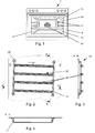
- Fig. 1 shows a cooking appliance 1 in a frontal view and the view through the cooking appliance door.
- an insert carrier 20 is mounted, which comprises a frame member 24 with guides 22.
- the frame member consists of two coarse vertical, but slightly oblique, aligned wire brackets 24, at which at regular intervals and roughly horizontally, but slightly oblique, aligned guides 22 are attached.
- the guides 22 comprise two spaced-apart wire hoops 26 spaced apart from one another and dimensioned such that the leading edge 42 of the baking tray 40 can be guided therein.
- each side wall 15 is attached to each side wall 15 at a small angle of inclination of 2 °, which is sloping from the muffle opening 11 to the device interior 12.
- angle ⁇ is shown oversized.
- the insert carrier of the muffle opening is therefore a little bit higher than in the interior of the device, so for example adjacent to the fan.
- a region of the longitudinal struts 26 serves as a stop edge 27.
- Fig. 5 shows a Baking tray 40 so that it can be inserted with its edge shown on the left in the muffle.
- the guide edges 42 engage in the guides 22 of the insert carrier 20.
- Stops 44 are impressed as local depressions in the guide edges 42 at a distance of 2/3 to 3/4 of the baking tray depth away from the front edge of the baking tray. As soon as these stops 44 come into contact with the stop edges 27 when the baking tray 40 is pulled out of the muffle, the user senses a noticeable resistance to further pulling out and recognizes that the outer end position of the baking tray has been reached.
- the maximum skew angle in the outer end position is partially compensated. If, for example, an exactly horizontal extension direction of the food support would result in a tilt angle of 7 °, this is thus reduced to a permissible 5 °.
- bores are provided on side walls, in which a made of plastic bush insert 28 is inserted. Due to elastic deformation when inserting the female insert 28 into the opening of the bore, a flange of the female insert, which is larger than the bore itself, can be inserted and thus positively hold the female insert on the side wall.
- the frame members 24 have a U-shaped basic shape and at the end of the flanks a circumferential groove, in which engage the socket insert 28 integrally formed locking lugs and so the respective frame member 24 is held on the side wall 15.
Landscapes
- Engineering & Computer Science (AREA)
- Chemical & Material Sciences (AREA)
- Combustion & Propulsion (AREA)
- Mechanical Engineering (AREA)
- General Engineering & Computer Science (AREA)
- Baking, Grill, Roasting (AREA)
Abstract
Description
- Die Erfindung betrifft ein Gargerät gemäß dem Oberbegriff des Anspruchs 1.
- In Gargeräten werden Backbleche aufgenommen, um in mehreren Ebenen übereinander Gargut in die Gargerätemuffel einzubringen. Bei der Bestückung des Backblechs wird dieses aus dem Gargerät herausgezogen. Dafür sind an den Seitenwänden der Gargerätemuffel Führungen angeordnet. In einem weit aus dem Ofen herausgezogenen Zustand wird das Backblech nur an seinem hinteren Bereich gehalten. So bewirkt das Gewicht des Garguts ein Biegemoment, welches bewirkt, dass sich das vordere Ende des Bleches nach unten neigt. Sofern der Schräglagewinkel zu groß wird, so besteht die Gefahr, dass das Gargut nach vorne rutschend vom Backblech fällt. Normgemäß gemäß IEC 60335-2-6 ist der maximal zulässige Schräglagewinkel 6°. Um den Schräglagewinkel gering zu halten, ist es bekannt, zum einen das Spiel in den Führungen möglichst klein zu halten. Zum anderen werden Materialien mit hoher Steifigkeit oder entsprechend hoher Materialstärke verwendet, um die elastischen Deformationen, und somit den Kippwinkel, bei den Belastungen möglichst gering zu halten.
- Aufgabe der vorliegenden Erfindung ist, ein Gargerät mit Gargutträgern bereitzustellen, bei dem der maximal zulässige Kippwinkel eingehalten wird und das einfach und kostengünstig zu fertigen ist.
- Diese Aufgabe wird durch die Merkmale des Anspruchs 1 gelöst.
- Erfinderisch wird ein Gargerät mit einer Mehrzahl von Führungen zur Führung von Gargutträgern, insbesondere Backblechen, bereitgestellt, wobei die Führungen an den Seitenwänden der Gargerätemuffel angeordnet sind. Dabei ist die Auszugsrichtung der Führungen in einem Neigungswinkel von mindestens 1° gegenüber der Horizontalen von der Muffelöffnung zum Gargerätinneren abfallend. Da der Neigungswinkel der Führungen entgegengesetzt zu dem sich ergebenden Schräglagewinkel des Gargutträgers in der ausgezogenen Stellung, bzw. äußeren Endlage, wirkt, wird durch den Neigungswinkel der Schräglagewinkel reduziert, was die Gefahr des Herabrutschens von Gargut vom Gargutträger reduziert.
- Insbesondere ist an den Seitenwänden ein Einsatzträger mit einer Mehrzahl der Führungen angeordnet. Gegenüber einer Prägung der Führungen in die Seitenwand der Muffel bietet der Einsatzträger den Vorteil der genaueren Führung mit engeren Toleranzen. Mit Hilfe des Einsatzträgers kann ein im Wesentlichen paralleler Schlitz zur Aufnahme einer Führungskante des Backblechs geschaffen werden, wogegen eine derartige Form nur mit hohem Aufwand prägend erzielt werden kann. An Befestigungspunkten (wie bspw. gestanzten Öffnungen) wird der Einsatzträger an der Muffelseitenwand befestigt. Der Neigungswinkel kann einfach durch die "verdrehte" Positionierung der Befestigungspunkte an der Seitenwand erzielt werden, was in der Produktion keine besonderen Kosten verursacht und somit deutlich kostengünstiger ist, als eine mechanisch/elastisch steifere Ausgestaltung des Backblechs und dessen Führung.
- Weiterführend weist der Einsatzträger ein die Führungen verbindendes Rahmenelement auf, welches senkrecht zur Auszugsrichtung der Führungen ausgerichtet ist. Hierdurch wird erzielt, dass der Einsatzträger selbst den Neigungswinkel nicht erzeugt, bzw. aufweist, sondern dieser ergibt sich durch eine leicht verdrehte Befestigung des Einsatzträgers an der Seitenwand. Dies bedeutet, dass jeweils ein identischer Einsatzträger an der linken und rechten Seitenwand der Muffel verwendet werden kann, was die Einzelteilkosten reduziert und die Montage vereinfacht.
- Alternativ können die Führungen als Prägungen in den Seitenwänden der Gargerätemuffel ausgeführt sein. Dies ist eine kostengünstige Variante, da hier kein gesonderter Einsatzträger benötigt wird.
- Weiterführend ist der Neigungswinkel kleiner als 6°, da bei einem größeren Neigungswinkel die Gefahr bestehen würde, dass Gargut vom Backblech in der komplett eingeschobenen Stellung des Backblechs in den Ofen nach hinten rutschen würde. Dieses Rutschen könnte sowohl durch den Neigungswinkel selbst, als auch durch den verbleibenden Impuls des Garguts beim Abbremsen des Backblechs beim Erreichen der eingeschobenen Stellung verursacht werden.
- Insbesondere weist der Einsatzträger als Rahmen zwei Drahtbügel auf und die Führungen der Gargutträger sind jeweils als zwei parallel zueinander liegende Längsstreben ausgeführt. Durch diese einfache Bauweise werden die Bauteilkosten reduziert und die Masse des Einsatzträgers kann gering gehalten werden, was die Erwärmungsgeschwindigkeit des Gargeräts verbessert.
- Alternativ sind die Führungen des Einsatzträgers als Teleskoplagerungen ausgeführt, was den Vorteil bewirkt, dass das Backblech zu 100% oder mehr aus der Muffel gezogen werden kann.
- Insbesondere ist ein Auszugsstopp als Begrenzung der Auszugsbewegung des Gargutträgers aus der Führung vorgesehen, so dass durch irrtümliches zu weites Ausziehen zum einen nicht das Backblech herausfallen kann und zum anderen bei zu weitem Herausziehen sich kein zu großer Schräglagewinkel ergeben kann.
- Im Folgenden wird die Erfindung mit Bezug auf die Zeichnungen anhand von bevorzugten Ausführungsformen beispielhaft beschrieben. Es zeigen:
- Fig. 1
- eine Draufsicht auf ein Gargerät,
- Fig. 2
- eine Ansicht einer Seitenwand der Garraummuffel mit einem Einsatzträger,
- Fig. 3
- den Schnitt B - B durch den Einsatzträger,
- Fig. 4
- den Schnitt A - A durch den Einsatzträger und
- Fig. 5
- eine Seitenansicht des Backblechs.
-
Fig. 1 zeigt ein Gargerät 1 in einer frontalen Ansicht und den Blick durch die Gargerätetür. An beiden seitlichen Wänden 15 ist ein Einsatzträger 20 angebracht, der ein Rahmenelement 24 mit Führungen 22 umfasst. Das Rahmenelement besteht aus zwei im Groben vertikal, dabei aber leicht schräg, ausgerichteten Drahtbügeln 24, an denen in regelmäßigen Abständen und im Groben horizontal, dabei aber leicht schräg, ausgerichtete Führungen 22 befestigt sind. Die Führungen 22 umfassen zwei beabstandete Drahtbügel 26 mit einem Abstand zueinander, der so bemessen ist, dass die Führungskante 42 des Backblechs 40 in ihm geführt werden kann. - Jeweils ein Einsatzträger 20 ist an jeder Seitenwand 15 unter einem geringen Neigungswinkel von 2° befestigt, der von der Muffelöffnung 11 zum Geräteinneren 12 abfallend ist. Aus Gründen der besseren Anschaulichkeit wurde in
Fig.2 der Winkel α übergroß dargestellt. Der Einsatzträger der Muffelöffnung liegt also um ein geringes Stück höher als im Geräteinneren, also z.B. dem Ventilator benachbart. - Um das maximale Herausziehen des Backblechs 40 aus der Backofenmuffel 10 zu begrenzen, dient ein Bereich der Längsstreben 26 als Anschlagkante 27.
Fig. 5 zeigt ein Backblech 40 so, dass es mit seiner links dargestellten Kante in die Muffel eingeführt werden kann. Dabei greifen die Führungskanten 42 in die Führungen 22 der Einsatzträger 20. Es sind bei einer Entfernung von 2/3 bis 3/4 der Backblechtiefe von der vorderen Kante des Backblechs entfernt Anschläge 44 als lokale Vertiefungen in die Führungskanten 42 eingeprägt. Sobald beim Herausziehen des Backblechs 40 aus der Muffel diese Anschläge 44 mit den Anschlagkanten 27 in Kontakt treten, so spürt der Anwender einen merklichen Widerstand gegen weiteres Herausziehen und erkennt, dass die äußere Endlage des Backblechs erreicht wurde. In dieser Lage liegt der Schwerpunkt des Backblechs und dem darauf befindlichen Gargut deutlich außerhalb der Muffel. Sowohl ein Spiel in der Führung des Backblechs, als auch elastische Deformationen der Lagerung sorgen dafür, dass das Backblech sich nach vorne herabneigt. Bei einer zu großen Neigung oder Schräglage besteht die Gefahr, dass das Gargut von dem Backblech rutscht. Es wurde erkannt, dass diese Gefahr dann groß ist, wenn der Schräglagewinkel in der äußeren Endlage größer als 6° ist und dieser maximale Winkel wird in der IEC 60335-2-6 gefordert. - Durch den Einbau des Einsatzträgers 20 mit dem beschriebenen Neigungswinkel α von 2° wird der maximale Schräglagewinkel in der äußeren Endlage teilweise kompensiert. Wenn beispielsweise bei einer exakt horizontalen Auszugsrichtung der Gargutträger sich ein Schräglagewinkel von 7° ergeben würde, wird dieser somit auf zulässige 5° reduziert.
- Zur Befestigung der Einsatzträger 20 an den Seitenwänden 15 sind an Seitenwänden Bohrungen vorgesehen, in welche ein aus Kunststoff gefertigter Buchseneinsatz 28 gesteckt wird. Aufgrund von elastischer Deformation beim Einstecken des Buchseneinsatzes 28 in die Öffnung der Bohrung kann ein Flansch des Buchseneinsatzes, der größer ist, als die Bohrung selbst, eingesteckt werden und so formschlüssig den Buchseneinsatz an der Seitenwand halten. Die Rahmenelemente 24 haben eine U-förmige Grundform und am Ende der Flanken eine umlaufende Rille, in welche am Buchseneinsatz 28 angeformte Rastnasen greifen und so wird das jeweilige Rahmenelement 24 an der Seitenwand 15 gehalten.
-
- 1.
- Gargerät
- 4.
- Gargerätetür
- 10.
- Gargerätmuffel
- 11.
- Muffelöffnung
- 12.
- Seite des Gargeräteinneren
- 15.
- Seitenwand
- 20.
- Einsatzträger
- 22.
- Führung
- 24.
- Drahtbügel, Rahmenelement
- 26.
- Längsstreben / Drahtbügel
- 28.
- Buchseneinsatz
- 40.
- Backblech / Gargutträger
- 42.
- Führungskante
- 44.
- Anschlag des Backblechs
Claims (10)
- Gargerät (1) mit einer Mehrzahl von Führungen (22) zur Führung von Gargutträgern (40), insbesondere Backblechen, wobei die Führungen (22) an den Seitenwänden (15) der Gargerätemuffel (10) angeordnet sind
dadurch gekennzeichnet, dass
die Auszugsrichtung der Führungen (22) in einem Neigungswinkel (α) von mindestens 1° gegenüber der Horizontalen von der Muffelöffnung (11) zum Gargerätinneren (12) abfallend ist. - Gargerät gemäß Anspruch 1, dadurch gekennzeichnet, dass an den Seitenwänden (12) ein Einsatzträger (20) mit der Mehrzahl der Führungen (22) angeordnet ist.
- Gargerät gemäß Anspruch 2, dadurch gekennzeichnet, dass der Einsatzträger (20) ein die Führungen verbindendes Rahmenelement (24) aufweist, welches senkrecht zur Auszugsrichtung der Führungen (22) ausgerichtet ist.
- Gargerät gemäß Anspruch 2 oder 3, dadurch gekennzeichnet, dass der Einsatzträger (20) im Neigungswinkel (α) an der Seitenwand (15) befestigt ist.
- Gargerät (1) gemäß einem der Ansprüche 2 bis 4, dadurch gekennzeichnet, dass an beiden Seitenwänden (15) der Gargerätemuffel (10) ein baugleicher Einsatzträger (20) angeordnet ist.
- Gargerät (1) gemäß einem der vorangegangenen Ansprüche, dadurch gekennzeichnet, dass die Führungen (22) als Prägungen in den Seitenwänden der Gargerätemuffel (11) ausgeführt sind.
- Gargerät gemäß einem der vorangegangenen Ansprüche, dadurch gekennzeichnet, dass der Neigungswinkel (α) kleiner als 6° ist.
- Gargerät gemäß einem der vorangegangenen Ansprüche dadurch gekennzeichnet, dass der Einsatzträger (20) als Rahmen zwei Drahtbügel (24) aufweist, und die Führungen (22) der Gargutträger jeweils als zwei parallel zueinander liegende Längsstreben (26) ausgeführt sind.
- Gargerät gemäß einem der Ansprüche 2 bis 6, dadurch gekennzeichnet, dass die Führungen des Einsatzträgers (20) als Teleskoplagerungen ausgeführt sind.
- Gargerät gemäß einem der vorangegangenen Ansprüche mit einem Gargutträger (40), dadurch gekennzeichnet, dass ein Auszugsstopp als Begrenzung der Auszugsbewegung des Gargutträgers (40) aus der Führung vorgesehen ist.
Priority Applications (1)
| Application Number | Priority Date | Filing Date | Title |
|---|---|---|---|
| PL11181922T PL2436990T3 (pl) | 2010-10-04 | 2011-09-20 | Urządzenie do gotowania |
Applications Claiming Priority (1)
| Application Number | Priority Date | Filing Date | Title |
|---|---|---|---|
| DE102010041935A DE102010041935A1 (de) | 2010-10-04 | 2010-10-04 | Gargerät |
Publications (3)
| Publication Number | Publication Date |
|---|---|
| EP2436990A2 true EP2436990A2 (de) | 2012-04-04 |
| EP2436990A3 EP2436990A3 (de) | 2017-12-06 |
| EP2436990B1 EP2436990B1 (de) | 2019-07-03 |
Family
ID=44970931
Family Applications (1)
| Application Number | Title | Priority Date | Filing Date |
|---|---|---|---|
| EP11181922.3A Active EP2436990B1 (de) | 2010-10-04 | 2011-09-20 | Gargerät |
Country Status (4)
| Country | Link |
|---|---|
| EP (1) | EP2436990B1 (de) |
| DE (1) | DE102010041935A1 (de) |
| ES (1) | ES2735974T3 (de) |
| PL (1) | PL2436990T3 (de) |
Cited By (2)
| Publication number | Priority date | Publication date | Assignee | Title |
|---|---|---|---|---|
| EP2743592A1 (de) * | 2012-12-11 | 2014-06-18 | BSH Bosch und Siemens Hausgeräte GmbH | Backblech für Kochgeräte |
| ES2603780A1 (es) * | 2015-09-01 | 2017-03-01 | Bsh Electrodomésticos España, S.A. | Sistema de aparato de cocción |
Families Citing this family (3)
| Publication number | Priority date | Publication date | Assignee | Title |
|---|---|---|---|---|
| US12035845B1 (en) | 2023-04-26 | 2024-07-16 | Sharkninja Operating Llc | Systems and methods for cooking pizza |
| US12372247B2 (en) | 2023-04-26 | 2025-07-29 | Sharkninja Operating Llc | Systems and methods for cooking pizza |
| USD1104596S1 (en) | 2023-05-31 | 2025-12-09 | Sharkninja Operating Llc | Cooking device |
Family Cites Families (8)
| Publication number | Priority date | Publication date | Assignee | Title |
|---|---|---|---|---|
| CH520899A (de) * | 1970-07-24 | 1972-03-31 | Siemens Elektrogeraete Gmbh | Herd, insbesondere Elektroherd |
| DE8515431U1 (de) * | 1985-05-24 | 1987-05-14 | Bosch-Siemens Hausgeräte GmbH, 8000 München | Backofen |
| EP0707177A1 (de) * | 1994-10-06 | 1996-04-17 | V-Zug AG | Führungsgitter für Backofenbleche und mit solchen Führungsgittern ausgerüstete Backofenröhre |
| US7216646B2 (en) * | 2002-07-10 | 2007-05-15 | Accuride International Inc. | Oven rack with slide assembly |
| DE10253158B4 (de) * | 2002-11-14 | 2008-01-24 | BSH Bosch und Siemens Hausgeräte GmbH | Backofen |
| US7735481B1 (en) * | 2007-08-17 | 2010-06-15 | Capital Cooking Equipment, Inc. | Oven rack having hinged rollers |
| PL2093497T3 (pl) * | 2008-02-21 | 2013-10-31 | Electrolux Home Products Corp Nv | Przedział do gotowania z ramą boczną i sposób mocowania ramy bocznej |
| ITVA20080027U1 (it) * | 2008-12-18 | 2010-06-19 | Whirlpool Co | Sistema di supporto e scorrimento per ripiani estraibili da un forno. |
-
2010
- 2010-10-04 DE DE102010041935A patent/DE102010041935A1/de not_active Withdrawn
-
2011
- 2011-09-20 PL PL11181922T patent/PL2436990T3/pl unknown
- 2011-09-20 EP EP11181922.3A patent/EP2436990B1/de active Active
- 2011-09-20 ES ES11181922T patent/ES2735974T3/es active Active
Non-Patent Citations (1)
| Title |
|---|
| None |
Cited By (2)
| Publication number | Priority date | Publication date | Assignee | Title |
|---|---|---|---|---|
| EP2743592A1 (de) * | 2012-12-11 | 2014-06-18 | BSH Bosch und Siemens Hausgeräte GmbH | Backblech für Kochgeräte |
| ES2603780A1 (es) * | 2015-09-01 | 2017-03-01 | Bsh Electrodomésticos España, S.A. | Sistema de aparato de cocción |
Also Published As
| Publication number | Publication date |
|---|---|
| DE102010041935A1 (de) | 2012-04-05 |
| EP2436990B1 (de) | 2019-07-03 |
| ES2735974T3 (es) | 2019-12-23 |
| EP2436990A3 (de) | 2017-12-06 |
| PL2436990T3 (pl) | 2019-12-31 |
Similar Documents
| Publication | Publication Date | Title |
|---|---|---|
| EP1840473B1 (de) | Haushaltsgerät mit einer an einem Traggestell befestigten Teleskopauszugsvorrichtung | |
| DE102013102846B4 (de) | Auszugsführung, Haushaltsgerät und Möbel mit einer Auszugsführung und Nachrüstsatz | |
| DE202008000887U1 (de) | Montagesystem | |
| EP1306622A1 (de) | Schienensystem für Gargutträger in einem Backofen | |
| EP2436990B1 (de) | Gargerät | |
| EP1642066B1 (de) | Gargutträgerauszugsystem | |
| EP3022506A1 (de) | Haushaltskältegerät mit einem ablageboden und ein verschiebbar daran angeordnetes griffteil | |
| EP2615380B1 (de) | Garraumeinschub | |
| EP1459014A1 (de) | Auszugssystem eines haushaltsgeräts, insbesondere eines gargeräts | |
| EP2719955B1 (de) | Schienenauszugsvorrichtung für einen gargutträger | |
| EP2292980B1 (de) | Backofen mit einem mittels Rastung gesicherten Einschub | |
| EP2500661B1 (de) | Vorrichtung mit einem Gargutträger, für ein Gargerät, Gargerät mit einem entsprechenden Vorrichtung sowie Verfahren zum Bewegen eines Gargutträgers in einer Aufnahme | |
| EP2645003B1 (de) | Gargutträger für ein Gargerät | |
| EP2454542B1 (de) | Kühlgutträger für ein kältegerät | |
| EP4286749A1 (de) | Schnellbefestigungssystem für einen teleskopauszug | |
| EP3034950B1 (de) | Vorrichtung zur auflage von gargutträgern | |
| EP3029383B1 (de) | Dunstabzugshaube | |
| EP2520866B1 (de) | Backofen | |
| DE102012011844A1 (de) | Trägergitter für ein Gerät | |
| EP3425283B1 (de) | Befestigungsanordnung zum befestigen eines abstützteils eines gargutträgers, insbesondere für ein gargerät | |
| DE102004025755A1 (de) | Schublade | |
| DE102010042706A1 (de) | Backbaugruppe | |
| DE202015100718U1 (de) | System zur Montage einer Teleskopschiene in einem Backofen | |
| DE102011087219A1 (de) | Gargutträgerauszug | |
| EP2469181B1 (de) | Vorrichtung zum Halten eines Gargutträgers in einem Garraum eines Gargeräts sowie Gargerät mit einer derartigen Vorrichtung |
Legal Events
| Date | Code | Title | Description |
|---|---|---|---|
| PUAI | Public reference made under article 153(3) epc to a published international application that has entered the european phase |
Free format text: ORIGINAL CODE: 0009012 |
|
| AK | Designated contracting states |
Kind code of ref document: A2 Designated state(s): AL AT BE BG CH CY CZ DE DK EE ES FI FR GB GR HR HU IE IS IT LI LT LU LV MC MK MT NL NO PL PT RO RS SE SI SK SM TR |
|
| AX | Request for extension of the european patent |
Extension state: BA ME |
|
| RAP1 | Party data changed (applicant data changed or rights of an application transferred) |
Owner name: BSH HAUSGERAETE GMBH |
|
| PUAL | Search report despatched |
Free format text: ORIGINAL CODE: 0009013 |
|
| AK | Designated contracting states |
Kind code of ref document: A3 Designated state(s): AL AT BE BG CH CY CZ DE DK EE ES FI FR GB GR HR HU IE IS IT LI LT LU LV MC MK MT NL NO PL PT RO RS SE SI SK SM TR |
|
| AX | Request for extension of the european patent |
Extension state: BA ME |
|
| RIC1 | Information provided on ipc code assigned before grant |
Ipc: F24C 15/16 20060101AFI20171030BHEP |
|
| STAA | Information on the status of an ep patent application or granted ep patent |
Free format text: STATUS: REQUEST FOR EXAMINATION WAS MADE |
|
| 17P | Request for examination filed |
Effective date: 20180606 |
|
| RBV | Designated contracting states (corrected) |
Designated state(s): AL AT BE BG CH CY CZ DE DK EE ES FI FR GB GR HR HU IE IS IT LI LT LU LV MC MK MT NL NO PL PT RO RS SE SI SK SM TR |
|
| GRAP | Despatch of communication of intention to grant a patent |
Free format text: ORIGINAL CODE: EPIDOSNIGR1 |
|
| STAA | Information on the status of an ep patent application or granted ep patent |
Free format text: STATUS: GRANT OF PATENT IS INTENDED |
|
| INTG | Intention to grant announced |
Effective date: 20190201 |
|
| GRAS | Grant fee paid |
Free format text: ORIGINAL CODE: EPIDOSNIGR3 |
|
| GRAA | (expected) grant |
Free format text: ORIGINAL CODE: 0009210 |
|
| STAA | Information on the status of an ep patent application or granted ep patent |
Free format text: STATUS: THE PATENT HAS BEEN GRANTED |
|
| AK | Designated contracting states |
Kind code of ref document: B1 Designated state(s): AL AT BE BG CH CY CZ DE DK EE ES FI FR GB GR HR HU IE IS IT LI LT LU LV MC MK MT NL NO PL PT RO RS SE SI SK SM TR |
|
| REG | Reference to a national code |
Ref country code: GB Ref legal event code: FG4D Free format text: NOT ENGLISH |
|
| REG | Reference to a national code |
Ref country code: CH Ref legal event code: EP Ref country code: AT Ref legal event code: REF Ref document number: 1151485 Country of ref document: AT Kind code of ref document: T Effective date: 20190715 |
|
| REG | Reference to a national code |
Ref country code: IE Ref legal event code: FG4D Free format text: LANGUAGE OF EP DOCUMENT: GERMAN |
|
| REG | Reference to a national code |
Ref country code: DE Ref legal event code: R096 Ref document number: 502011015862 Country of ref document: DE |
|
| REG | Reference to a national code |
Ref country code: NL Ref legal event code: MP Effective date: 20190703 |
|
| REG | Reference to a national code |
Ref country code: LT Ref legal event code: MG4D |
|
| REG | Reference to a national code |
Ref country code: ES Ref legal event code: FG2A Ref document number: 2735974 Country of ref document: ES Kind code of ref document: T3 Effective date: 20191223 |
|
| PG25 | Lapsed in a contracting state [announced via postgrant information from national office to epo] |
Ref country code: SE Free format text: LAPSE BECAUSE OF FAILURE TO SUBMIT A TRANSLATION OF THE DESCRIPTION OR TO PAY THE FEE WITHIN THE PRESCRIBED TIME-LIMIT Effective date: 20190703 Ref country code: LT Free format text: LAPSE BECAUSE OF FAILURE TO SUBMIT A TRANSLATION OF THE DESCRIPTION OR TO PAY THE FEE WITHIN THE PRESCRIBED TIME-LIMIT Effective date: 20190703 Ref country code: BG Free format text: LAPSE BECAUSE OF FAILURE TO SUBMIT A TRANSLATION OF THE DESCRIPTION OR TO PAY THE FEE WITHIN THE PRESCRIBED TIME-LIMIT Effective date: 20191003 Ref country code: PT Free format text: LAPSE BECAUSE OF FAILURE TO SUBMIT A TRANSLATION OF THE DESCRIPTION OR TO PAY THE FEE WITHIN THE PRESCRIBED TIME-LIMIT Effective date: 20191104 Ref country code: NL Free format text: LAPSE BECAUSE OF FAILURE TO SUBMIT A TRANSLATION OF THE DESCRIPTION OR TO PAY THE FEE WITHIN THE PRESCRIBED TIME-LIMIT Effective date: 20190703 Ref country code: NO Free format text: LAPSE BECAUSE OF FAILURE TO SUBMIT A TRANSLATION OF THE DESCRIPTION OR TO PAY THE FEE WITHIN THE PRESCRIBED TIME-LIMIT Effective date: 20191003 Ref country code: CZ Free format text: LAPSE BECAUSE OF FAILURE TO SUBMIT A TRANSLATION OF THE DESCRIPTION OR TO PAY THE FEE WITHIN THE PRESCRIBED TIME-LIMIT Effective date: 20190703 Ref country code: FI Free format text: LAPSE BECAUSE OF FAILURE TO SUBMIT A TRANSLATION OF THE DESCRIPTION OR TO PAY THE FEE WITHIN THE PRESCRIBED TIME-LIMIT Effective date: 20190703 Ref country code: HR Free format text: LAPSE BECAUSE OF FAILURE TO SUBMIT A TRANSLATION OF THE DESCRIPTION OR TO PAY THE FEE WITHIN THE PRESCRIBED TIME-LIMIT Effective date: 20190703 |
|
| PG25 | Lapsed in a contracting state [announced via postgrant information from national office to epo] |
Ref country code: LV Free format text: LAPSE BECAUSE OF FAILURE TO SUBMIT A TRANSLATION OF THE DESCRIPTION OR TO PAY THE FEE WITHIN THE PRESCRIBED TIME-LIMIT Effective date: 20190703 Ref country code: IS Free format text: LAPSE BECAUSE OF FAILURE TO SUBMIT A TRANSLATION OF THE DESCRIPTION OR TO PAY THE FEE WITHIN THE PRESCRIBED TIME-LIMIT Effective date: 20191103 Ref country code: AL Free format text: LAPSE BECAUSE OF FAILURE TO SUBMIT A TRANSLATION OF THE DESCRIPTION OR TO PAY THE FEE WITHIN THE PRESCRIBED TIME-LIMIT Effective date: 20190703 Ref country code: GR Free format text: LAPSE BECAUSE OF FAILURE TO SUBMIT A TRANSLATION OF THE DESCRIPTION OR TO PAY THE FEE WITHIN THE PRESCRIBED TIME-LIMIT Effective date: 20191004 Ref country code: RS Free format text: LAPSE BECAUSE OF FAILURE TO SUBMIT A TRANSLATION OF THE DESCRIPTION OR TO PAY THE FEE WITHIN THE PRESCRIBED TIME-LIMIT Effective date: 20190703 |
|
| PG25 | Lapsed in a contracting state [announced via postgrant information from national office to epo] |
Ref country code: DK Free format text: LAPSE BECAUSE OF FAILURE TO SUBMIT A TRANSLATION OF THE DESCRIPTION OR TO PAY THE FEE WITHIN THE PRESCRIBED TIME-LIMIT Effective date: 20190703 Ref country code: IT Free format text: LAPSE BECAUSE OF FAILURE TO SUBMIT A TRANSLATION OF THE DESCRIPTION OR TO PAY THE FEE WITHIN THE PRESCRIBED TIME-LIMIT Effective date: 20190703 Ref country code: EE Free format text: LAPSE BECAUSE OF FAILURE TO SUBMIT A TRANSLATION OF THE DESCRIPTION OR TO PAY THE FEE WITHIN THE PRESCRIBED TIME-LIMIT Effective date: 20190703 Ref country code: RO Free format text: LAPSE BECAUSE OF FAILURE TO SUBMIT A TRANSLATION OF THE DESCRIPTION OR TO PAY THE FEE WITHIN THE PRESCRIBED TIME-LIMIT Effective date: 20190703 |
|
| PG25 | Lapsed in a contracting state [announced via postgrant information from national office to epo] |
Ref country code: IS Free format text: LAPSE BECAUSE OF FAILURE TO SUBMIT A TRANSLATION OF THE DESCRIPTION OR TO PAY THE FEE WITHIN THE PRESCRIBED TIME-LIMIT Effective date: 20200224 Ref country code: SK Free format text: LAPSE BECAUSE OF FAILURE TO SUBMIT A TRANSLATION OF THE DESCRIPTION OR TO PAY THE FEE WITHIN THE PRESCRIBED TIME-LIMIT Effective date: 20190703 Ref country code: MC Free format text: LAPSE BECAUSE OF FAILURE TO SUBMIT A TRANSLATION OF THE DESCRIPTION OR TO PAY THE FEE WITHIN THE PRESCRIBED TIME-LIMIT Effective date: 20190703 Ref country code: SM Free format text: LAPSE BECAUSE OF FAILURE TO SUBMIT A TRANSLATION OF THE DESCRIPTION OR TO PAY THE FEE WITHIN THE PRESCRIBED TIME-LIMIT Effective date: 20190703 |
|
| REG | Reference to a national code |
Ref country code: CH Ref legal event code: PL |
|
| REG | Reference to a national code |
Ref country code: DE Ref legal event code: R097 Ref document number: 502011015862 Country of ref document: DE |
|
| PLBE | No opposition filed within time limit |
Free format text: ORIGINAL CODE: 0009261 |
|
| STAA | Information on the status of an ep patent application or granted ep patent |
Free format text: STATUS: NO OPPOSITION FILED WITHIN TIME LIMIT |
|
| PG2D | Information on lapse in contracting state deleted |
Ref country code: IS |
|
| PG25 | Lapsed in a contracting state [announced via postgrant information from national office to epo] |
Ref country code: CH Free format text: LAPSE BECAUSE OF NON-PAYMENT OF DUE FEES Effective date: 20190930 Ref country code: IE Free format text: LAPSE BECAUSE OF NON-PAYMENT OF DUE FEES Effective date: 20190920 Ref country code: LI Free format text: LAPSE BECAUSE OF NON-PAYMENT OF DUE FEES Effective date: 20190930 Ref country code: LU Free format text: LAPSE BECAUSE OF NON-PAYMENT OF DUE FEES Effective date: 20190920 |
|
| 26N | No opposition filed |
Effective date: 20200603 |
|
| REG | Reference to a national code |
Ref country code: BE Ref legal event code: MM Effective date: 20190930 |
|
| PG25 | Lapsed in a contracting state [announced via postgrant information from national office to epo] |
Ref country code: SI Free format text: LAPSE BECAUSE OF FAILURE TO SUBMIT A TRANSLATION OF THE DESCRIPTION OR TO PAY THE FEE WITHIN THE PRESCRIBED TIME-LIMIT Effective date: 20190703 Ref country code: BE Free format text: LAPSE BECAUSE OF NON-PAYMENT OF DUE FEES Effective date: 20190930 |
|
| PG25 | Lapsed in a contracting state [announced via postgrant information from national office to epo] |
Ref country code: FR Free format text: LAPSE BECAUSE OF NON-PAYMENT OF DUE FEES Effective date: 20190930 |
|
| REG | Reference to a national code |
Ref country code: AT Ref legal event code: MM01 Ref document number: 1151485 Country of ref document: AT Kind code of ref document: T Effective date: 20190920 |
|
| PG25 | Lapsed in a contracting state [announced via postgrant information from national office to epo] |
Ref country code: AT Free format text: LAPSE BECAUSE OF NON-PAYMENT OF DUE FEES Effective date: 20190920 |
|
| PG25 | Lapsed in a contracting state [announced via postgrant information from national office to epo] |
Ref country code: CY Free format text: LAPSE BECAUSE OF FAILURE TO SUBMIT A TRANSLATION OF THE DESCRIPTION OR TO PAY THE FEE WITHIN THE PRESCRIBED TIME-LIMIT Effective date: 20190703 |
|
| PG25 | Lapsed in a contracting state [announced via postgrant information from national office to epo] |
Ref country code: HU Free format text: LAPSE BECAUSE OF FAILURE TO SUBMIT A TRANSLATION OF THE DESCRIPTION OR TO PAY THE FEE WITHIN THE PRESCRIBED TIME-LIMIT; INVALID AB INITIO Effective date: 20110920 Ref country code: MT Free format text: LAPSE BECAUSE OF FAILURE TO SUBMIT A TRANSLATION OF THE DESCRIPTION OR TO PAY THE FEE WITHIN THE PRESCRIBED TIME-LIMIT Effective date: 20190703 |
|
| PG25 | Lapsed in a contracting state [announced via postgrant information from national office to epo] |
Ref country code: MK Free format text: LAPSE BECAUSE OF FAILURE TO SUBMIT A TRANSLATION OF THE DESCRIPTION OR TO PAY THE FEE WITHIN THE PRESCRIBED TIME-LIMIT Effective date: 20190703 |
|
| REG | Reference to a national code |
Ref country code: DE Ref legal event code: R084 Ref document number: 502011015862 Country of ref document: DE |
|
| PGFP | Annual fee paid to national office [announced via postgrant information from national office to epo] |
Ref country code: TR Payment date: 20230912 Year of fee payment: 13 Ref country code: GB Payment date: 20230921 Year of fee payment: 13 |
|
| PGFP | Annual fee paid to national office [announced via postgrant information from national office to epo] |
Ref country code: PL Payment date: 20230908 Year of fee payment: 13 Ref country code: DE Payment date: 20230930 Year of fee payment: 13 |
|
| PGFP | Annual fee paid to national office [announced via postgrant information from national office to epo] |
Ref country code: ES Payment date: 20231019 Year of fee payment: 13 |
|
| PGFP | Annual fee paid to national office [announced via postgrant information from national office to epo] |
Ref country code: DE Payment date: 20230930 Year of fee payment: 13 |
|
| REG | Reference to a national code |
Ref country code: ES Ref legal event code: GC2A Effective date: 20240731 |
|
| REG | Reference to a national code |
Ref country code: DE Ref legal event code: R119 Ref document number: 502011015862 Country of ref document: DE |
|
| GBPC | Gb: european patent ceased through non-payment of renewal fee |
Effective date: 20240920 |
|
| PG25 | Lapsed in a contracting state [announced via postgrant information from national office to epo] |
Ref country code: DE Free format text: LAPSE BECAUSE OF NON-PAYMENT OF DUE FEES Effective date: 20250401 |
|
| PG25 | Lapsed in a contracting state [announced via postgrant information from national office to epo] |
Ref country code: GB Free format text: LAPSE BECAUSE OF NON-PAYMENT OF DUE FEES Effective date: 20240920 |
|
| REG | Reference to a national code |
Ref country code: ES Ref legal event code: FD2A Effective date: 20251031 |
|
| PG25 | Lapsed in a contracting state [announced via postgrant information from national office to epo] |
Ref country code: ES Free format text: LAPSE BECAUSE OF NON-PAYMENT OF DUE FEES Effective date: 20240921 |
|
| PG25 | Lapsed in a contracting state [announced via postgrant information from national office to epo] |
Ref country code: PL Free format text: LAPSE BECAUSE OF NON-PAYMENT OF DUE FEES Effective date: 20240920 |