EP2436550A1 - Charging system, and method for controlling vehicle and charging system - Google Patents
Charging system, and method for controlling vehicle and charging system Download PDFInfo
- Publication number
- EP2436550A1 EP2436550A1 EP09845212A EP09845212A EP2436550A1 EP 2436550 A1 EP2436550 A1 EP 2436550A1 EP 09845212 A EP09845212 A EP 09845212A EP 09845212 A EP09845212 A EP 09845212A EP 2436550 A1 EP2436550 A1 EP 2436550A1
- Authority
- EP
- European Patent Office
- Prior art keywords
- charging
- unit
- storage device
- power storage
- vehicle
- Prior art date
- Legal status (The legal status is an assumption and is not a legal conclusion. Google has not performed a legal analysis and makes no representation as to the accuracy of the status listed.)
- Granted
Links
- 238000000034 method Methods 0.000 title claims description 8
- 238000001514 detection method Methods 0.000 claims description 41
- 230000008859 change Effects 0.000 claims description 17
- 102220171488 rs760746448 Human genes 0.000 claims description 7
- 238000012545 processing Methods 0.000 description 39
- 101100042610 Arabidopsis thaliana SIGB gene Proteins 0.000 description 33
- 230000001133 acceleration Effects 0.000 description 18
- 101100421503 Arabidopsis thaliana SIGA gene Proteins 0.000 description 17
- 101100294408 Saccharomyces cerevisiae (strain ATCC 204508 / S288c) MOT2 gene Proteins 0.000 description 16
- 101150117326 sigA gene Proteins 0.000 description 16
- 238000006243 chemical reaction Methods 0.000 description 13
- 238000010586 diagram Methods 0.000 description 12
- 230000004044 response Effects 0.000 description 12
- 230000007246 mechanism Effects 0.000 description 11
- 238000004891 communication Methods 0.000 description 10
- 238000012544 monitoring process Methods 0.000 description 8
- 230000037361 pathway Effects 0.000 description 8
- 238000009413 insulation Methods 0.000 description 7
- 230000002159 abnormal effect Effects 0.000 description 6
- 239000003638 chemical reducing agent Substances 0.000 description 6
- 230000008878 coupling Effects 0.000 description 4
- 238000010168 coupling process Methods 0.000 description 4
- 238000005859 coupling reaction Methods 0.000 description 4
- 230000005674 electromagnetic induction Effects 0.000 description 4
- 238000005516 engineering process Methods 0.000 description 3
- 230000007935 neutral effect Effects 0.000 description 3
- 239000003990 capacitor Substances 0.000 description 2
- 238000002485 combustion reaction Methods 0.000 description 2
- 230000005672 electromagnetic field Effects 0.000 description 2
- 239000000446 fuel Substances 0.000 description 2
- 238000004519 manufacturing process Methods 0.000 description 2
- 230000001360 synchronised effect Effects 0.000 description 2
- 101000766830 Homo sapiens Cdc42-interacting protein 4 Proteins 0.000 description 1
- 101000826399 Homo sapiens Sulfotransferase 1A1 Proteins 0.000 description 1
- HBBGRARXTFLTSG-UHFFFAOYSA-N Lithium ion Chemical compound [Li+] HBBGRARXTFLTSG-UHFFFAOYSA-N 0.000 description 1
- 230000036461 convulsion Effects 0.000 description 1
- 230000007423 decrease Effects 0.000 description 1
- 230000000694 effects Effects 0.000 description 1
- 230000005669 field effect Effects 0.000 description 1
- 238000009499 grossing Methods 0.000 description 1
- 229910052739 hydrogen Inorganic materials 0.000 description 1
- 239000001257 hydrogen Substances 0.000 description 1
- 230000006872 improvement Effects 0.000 description 1
- 229910001416 lithium ion Inorganic materials 0.000 description 1
- 239000000696 magnetic material Substances 0.000 description 1
- 229910044991 metal oxide Inorganic materials 0.000 description 1
- 150000004706 metal oxides Chemical class 0.000 description 1
- 238000012986 modification Methods 0.000 description 1
- 230000004048 modification Effects 0.000 description 1
- 230000010355 oscillation Effects 0.000 description 1
- 239000000843 powder Substances 0.000 description 1
- 230000008929 regeneration Effects 0.000 description 1
- 238000011069 regeneration method Methods 0.000 description 1
- 239000004065 semiconductor Substances 0.000 description 1
- 238000004804 winding Methods 0.000 description 1
Images


Classifications
-
- B—PERFORMING OPERATIONS; TRANSPORTING
- B60—VEHICLES IN GENERAL
- B60K—ARRANGEMENT OR MOUNTING OF PROPULSION UNITS OR OF TRANSMISSIONS IN VEHICLES; ARRANGEMENT OR MOUNTING OF PLURAL DIVERSE PRIME-MOVERS IN VEHICLES; AUXILIARY DRIVES FOR VEHICLES; INSTRUMENTATION OR DASHBOARDS FOR VEHICLES; ARRANGEMENTS IN CONNECTION WITH COOLING, AIR INTAKE, GAS EXHAUST OR FUEL SUPPLY OF PROPULSION UNITS IN VEHICLES
- B60K6/00—Arrangement or mounting of plural diverse prime-movers for mutual or common propulsion, e.g. hybrid propulsion systems comprising electric motors and internal combustion engines ; Control systems therefor, i.e. systems controlling two or more prime movers, or controlling one of these prime movers and any of the transmission, drive or drive units Informative references: mechanical gearings with secondary electric drive F16H3/72; arrangements for handling mechanical energy structurally associated with the dynamo-electric machine H02K7/00; machines comprising structurally interrelated motor and generator parts H02K51/00; dynamo-electric machines not otherwise provided for in H02K see H02K99/00
- B60K6/20—Arrangement or mounting of plural diverse prime-movers for mutual or common propulsion, e.g. hybrid propulsion systems comprising electric motors and internal combustion engines ; Control systems therefor, i.e. systems controlling two or more prime movers, or controlling one of these prime movers and any of the transmission, drive or drive units Informative references: mechanical gearings with secondary electric drive F16H3/72; arrangements for handling mechanical energy structurally associated with the dynamo-electric machine H02K7/00; machines comprising structurally interrelated motor and generator parts H02K51/00; dynamo-electric machines not otherwise provided for in H02K see H02K99/00 the prime-movers consisting of electric motors and internal combustion engines, e.g. HEVs
- B60K6/22—Arrangement or mounting of plural diverse prime-movers for mutual or common propulsion, e.g. hybrid propulsion systems comprising electric motors and internal combustion engines ; Control systems therefor, i.e. systems controlling two or more prime movers, or controlling one of these prime movers and any of the transmission, drive or drive units Informative references: mechanical gearings with secondary electric drive F16H3/72; arrangements for handling mechanical energy structurally associated with the dynamo-electric machine H02K7/00; machines comprising structurally interrelated motor and generator parts H02K51/00; dynamo-electric machines not otherwise provided for in H02K see H02K99/00 the prime-movers consisting of electric motors and internal combustion engines, e.g. HEVs characterised by apparatus, components or means specially adapted for HEVs
- B60K6/36—Arrangement or mounting of plural diverse prime-movers for mutual or common propulsion, e.g. hybrid propulsion systems comprising electric motors and internal combustion engines ; Control systems therefor, i.e. systems controlling two or more prime movers, or controlling one of these prime movers and any of the transmission, drive or drive units Informative references: mechanical gearings with secondary electric drive F16H3/72; arrangements for handling mechanical energy structurally associated with the dynamo-electric machine H02K7/00; machines comprising structurally interrelated motor and generator parts H02K51/00; dynamo-electric machines not otherwise provided for in H02K see H02K99/00 the prime-movers consisting of electric motors and internal combustion engines, e.g. HEVs characterised by apparatus, components or means specially adapted for HEVs characterised by the transmission gearings
- B60K6/365—Arrangement or mounting of plural diverse prime-movers for mutual or common propulsion, e.g. hybrid propulsion systems comprising electric motors and internal combustion engines ; Control systems therefor, i.e. systems controlling two or more prime movers, or controlling one of these prime movers and any of the transmission, drive or drive units Informative references: mechanical gearings with secondary electric drive F16H3/72; arrangements for handling mechanical energy structurally associated with the dynamo-electric machine H02K7/00; machines comprising structurally interrelated motor and generator parts H02K51/00; dynamo-electric machines not otherwise provided for in H02K see H02K99/00 the prime-movers consisting of electric motors and internal combustion engines, e.g. HEVs characterised by apparatus, components or means specially adapted for HEVs characterised by the transmission gearings with the gears having orbital motion
-
- B—PERFORMING OPERATIONS; TRANSPORTING
- B60—VEHICLES IN GENERAL
- B60K—ARRANGEMENT OR MOUNTING OF PROPULSION UNITS OR OF TRANSMISSIONS IN VEHICLES; ARRANGEMENT OR MOUNTING OF PLURAL DIVERSE PRIME-MOVERS IN VEHICLES; AUXILIARY DRIVES FOR VEHICLES; INSTRUMENTATION OR DASHBOARDS FOR VEHICLES; ARRANGEMENTS IN CONNECTION WITH COOLING, AIR INTAKE, GAS EXHAUST OR FUEL SUPPLY OF PROPULSION UNITS IN VEHICLES
- B60K6/00—Arrangement or mounting of plural diverse prime-movers for mutual or common propulsion, e.g. hybrid propulsion systems comprising electric motors and internal combustion engines ; Control systems therefor, i.e. systems controlling two or more prime movers, or controlling one of these prime movers and any of the transmission, drive or drive units Informative references: mechanical gearings with secondary electric drive F16H3/72; arrangements for handling mechanical energy structurally associated with the dynamo-electric machine H02K7/00; machines comprising structurally interrelated motor and generator parts H02K51/00; dynamo-electric machines not otherwise provided for in H02K see H02K99/00
- B60K6/20—Arrangement or mounting of plural diverse prime-movers for mutual or common propulsion, e.g. hybrid propulsion systems comprising electric motors and internal combustion engines ; Control systems therefor, i.e. systems controlling two or more prime movers, or controlling one of these prime movers and any of the transmission, drive or drive units Informative references: mechanical gearings with secondary electric drive F16H3/72; arrangements for handling mechanical energy structurally associated with the dynamo-electric machine H02K7/00; machines comprising structurally interrelated motor and generator parts H02K51/00; dynamo-electric machines not otherwise provided for in H02K see H02K99/00 the prime-movers consisting of electric motors and internal combustion engines, e.g. HEVs
- B60K6/42—Arrangement or mounting of plural diverse prime-movers for mutual or common propulsion, e.g. hybrid propulsion systems comprising electric motors and internal combustion engines ; Control systems therefor, i.e. systems controlling two or more prime movers, or controlling one of these prime movers and any of the transmission, drive or drive units Informative references: mechanical gearings with secondary electric drive F16H3/72; arrangements for handling mechanical energy structurally associated with the dynamo-electric machine H02K7/00; machines comprising structurally interrelated motor and generator parts H02K51/00; dynamo-electric machines not otherwise provided for in H02K see H02K99/00 the prime-movers consisting of electric motors and internal combustion engines, e.g. HEVs characterised by the architecture of the hybrid electric vehicle
- B60K6/44—Series-parallel type
- B60K6/445—Differential gearing distribution type
-
- B—PERFORMING OPERATIONS; TRANSPORTING
- B60—VEHICLES IN GENERAL
- B60L—PROPULSION OF ELECTRICALLY-PROPELLED VEHICLES; SUPPLYING ELECTRIC POWER FOR AUXILIARY EQUIPMENT OF ELECTRICALLY-PROPELLED VEHICLES; ELECTRODYNAMIC BRAKE SYSTEMS FOR VEHICLES IN GENERAL; MAGNETIC SUSPENSION OR LEVITATION FOR VEHICLES; MONITORING OPERATING VARIABLES OF ELECTRICALLY-PROPELLED VEHICLES; ELECTRIC SAFETY DEVICES FOR ELECTRICALLY-PROPELLED VEHICLES
- B60L15/00—Methods, circuits, or devices for controlling the traction-motor speed of electrically-propelled vehicles
- B60L15/007—Physical arrangements or structures of drive train converters specially adapted for the propulsion motors of electric vehicles
-
- B—PERFORMING OPERATIONS; TRANSPORTING
- B60—VEHICLES IN GENERAL
- B60L—PROPULSION OF ELECTRICALLY-PROPELLED VEHICLES; SUPPLYING ELECTRIC POWER FOR AUXILIARY EQUIPMENT OF ELECTRICALLY-PROPELLED VEHICLES; ELECTRODYNAMIC BRAKE SYSTEMS FOR VEHICLES IN GENERAL; MAGNETIC SUSPENSION OR LEVITATION FOR VEHICLES; MONITORING OPERATING VARIABLES OF ELECTRICALLY-PROPELLED VEHICLES; ELECTRIC SAFETY DEVICES FOR ELECTRICALLY-PROPELLED VEHICLES
- B60L3/00—Electric devices on electrically-propelled vehicles for safety purposes; Monitoring operating variables, e.g. speed, deceleration or energy consumption
- B60L3/0023—Detecting, eliminating, remedying or compensating for drive train abnormalities, e.g. failures within the drive train
-
- B—PERFORMING OPERATIONS; TRANSPORTING
- B60—VEHICLES IN GENERAL
- B60L—PROPULSION OF ELECTRICALLY-PROPELLED VEHICLES; SUPPLYING ELECTRIC POWER FOR AUXILIARY EQUIPMENT OF ELECTRICALLY-PROPELLED VEHICLES; ELECTRODYNAMIC BRAKE SYSTEMS FOR VEHICLES IN GENERAL; MAGNETIC SUSPENSION OR LEVITATION FOR VEHICLES; MONITORING OPERATING VARIABLES OF ELECTRICALLY-PROPELLED VEHICLES; ELECTRIC SAFETY DEVICES FOR ELECTRICALLY-PROPELLED VEHICLES
- B60L50/00—Electric propulsion with power supplied within the vehicle
- B60L50/10—Electric propulsion with power supplied within the vehicle using propulsion power supplied by engine-driven generators, e.g. generators driven by combustion engines
- B60L50/16—Electric propulsion with power supplied within the vehicle using propulsion power supplied by engine-driven generators, e.g. generators driven by combustion engines with provision for separate direct mechanical propulsion
-
- B—PERFORMING OPERATIONS; TRANSPORTING
- B60—VEHICLES IN GENERAL
- B60L—PROPULSION OF ELECTRICALLY-PROPELLED VEHICLES; SUPPLYING ELECTRIC POWER FOR AUXILIARY EQUIPMENT OF ELECTRICALLY-PROPELLED VEHICLES; ELECTRODYNAMIC BRAKE SYSTEMS FOR VEHICLES IN GENERAL; MAGNETIC SUSPENSION OR LEVITATION FOR VEHICLES; MONITORING OPERATING VARIABLES OF ELECTRICALLY-PROPELLED VEHICLES; ELECTRIC SAFETY DEVICES FOR ELECTRICALLY-PROPELLED VEHICLES
- B60L50/00—Electric propulsion with power supplied within the vehicle
- B60L50/50—Electric propulsion with power supplied within the vehicle using propulsion power supplied by batteries or fuel cells
- B60L50/60—Electric propulsion with power supplied within the vehicle using propulsion power supplied by batteries or fuel cells using power supplied by batteries
- B60L50/61—Electric propulsion with power supplied within the vehicle using propulsion power supplied by batteries or fuel cells using power supplied by batteries by batteries charged by engine-driven generators, e.g. series hybrid electric vehicles
-
- B—PERFORMING OPERATIONS; TRANSPORTING
- B60—VEHICLES IN GENERAL
- B60L—PROPULSION OF ELECTRICALLY-PROPELLED VEHICLES; SUPPLYING ELECTRIC POWER FOR AUXILIARY EQUIPMENT OF ELECTRICALLY-PROPELLED VEHICLES; ELECTRODYNAMIC BRAKE SYSTEMS FOR VEHICLES IN GENERAL; MAGNETIC SUSPENSION OR LEVITATION FOR VEHICLES; MONITORING OPERATING VARIABLES OF ELECTRICALLY-PROPELLED VEHICLES; ELECTRIC SAFETY DEVICES FOR ELECTRICALLY-PROPELLED VEHICLES
- B60L53/00—Methods of charging batteries, specially adapted for electric vehicles; Charging stations or on-board charging equipment therefor; Exchange of energy storage elements in electric vehicles
- B60L53/10—Methods of charging batteries, specially adapted for electric vehicles; Charging stations or on-board charging equipment therefor; Exchange of energy storage elements in electric vehicles characterised by the energy transfer between the charging station and the vehicle
- B60L53/12—Inductive energy transfer
- B60L53/126—Methods for pairing a vehicle and a charging station, e.g. establishing a one-to-one relation between a wireless power transmitter and a wireless power receiver
-
- B—PERFORMING OPERATIONS; TRANSPORTING
- B60—VEHICLES IN GENERAL
- B60L—PROPULSION OF ELECTRICALLY-PROPELLED VEHICLES; SUPPLYING ELECTRIC POWER FOR AUXILIARY EQUIPMENT OF ELECTRICALLY-PROPELLED VEHICLES; ELECTRODYNAMIC BRAKE SYSTEMS FOR VEHICLES IN GENERAL; MAGNETIC SUSPENSION OR LEVITATION FOR VEHICLES; MONITORING OPERATING VARIABLES OF ELECTRICALLY-PROPELLED VEHICLES; ELECTRIC SAFETY DEVICES FOR ELECTRICALLY-PROPELLED VEHICLES
- B60L53/00—Methods of charging batteries, specially adapted for electric vehicles; Charging stations or on-board charging equipment therefor; Exchange of energy storage elements in electric vehicles
- B60L53/10—Methods of charging batteries, specially adapted for electric vehicles; Charging stations or on-board charging equipment therefor; Exchange of energy storage elements in electric vehicles characterised by the energy transfer between the charging station and the vehicle
- B60L53/14—Conductive energy transfer
- B60L53/18—Cables specially adapted for charging electric vehicles
-
- B—PERFORMING OPERATIONS; TRANSPORTING
- B60—VEHICLES IN GENERAL
- B60L—PROPULSION OF ELECTRICALLY-PROPELLED VEHICLES; SUPPLYING ELECTRIC POWER FOR AUXILIARY EQUIPMENT OF ELECTRICALLY-PROPELLED VEHICLES; ELECTRODYNAMIC BRAKE SYSTEMS FOR VEHICLES IN GENERAL; MAGNETIC SUSPENSION OR LEVITATION FOR VEHICLES; MONITORING OPERATING VARIABLES OF ELECTRICALLY-PROPELLED VEHICLES; ELECTRIC SAFETY DEVICES FOR ELECTRICALLY-PROPELLED VEHICLES
- B60L53/00—Methods of charging batteries, specially adapted for electric vehicles; Charging stations or on-board charging equipment therefor; Exchange of energy storage elements in electric vehicles
- B60L53/20—Methods of charging batteries, specially adapted for electric vehicles; Charging stations or on-board charging equipment therefor; Exchange of energy storage elements in electric vehicles characterised by converters located in the vehicle
- B60L53/22—Constructional details or arrangements of charging converters specially adapted for charging electric vehicles
-
- B—PERFORMING OPERATIONS; TRANSPORTING
- B60—VEHICLES IN GENERAL
- B60L—PROPULSION OF ELECTRICALLY-PROPELLED VEHICLES; SUPPLYING ELECTRIC POWER FOR AUXILIARY EQUIPMENT OF ELECTRICALLY-PROPELLED VEHICLES; ELECTRODYNAMIC BRAKE SYSTEMS FOR VEHICLES IN GENERAL; MAGNETIC SUSPENSION OR LEVITATION FOR VEHICLES; MONITORING OPERATING VARIABLES OF ELECTRICALLY-PROPELLED VEHICLES; ELECTRIC SAFETY DEVICES FOR ELECTRICALLY-PROPELLED VEHICLES
- B60L53/00—Methods of charging batteries, specially adapted for electric vehicles; Charging stations or on-board charging equipment therefor; Exchange of energy storage elements in electric vehicles
- B60L53/30—Constructional details of charging stations
- B60L53/305—Communication interfaces
-
- B—PERFORMING OPERATIONS; TRANSPORTING
- B60—VEHICLES IN GENERAL
- B60L—PROPULSION OF ELECTRICALLY-PROPELLED VEHICLES; SUPPLYING ELECTRIC POWER FOR AUXILIARY EQUIPMENT OF ELECTRICALLY-PROPELLED VEHICLES; ELECTRODYNAMIC BRAKE SYSTEMS FOR VEHICLES IN GENERAL; MAGNETIC SUSPENSION OR LEVITATION FOR VEHICLES; MONITORING OPERATING VARIABLES OF ELECTRICALLY-PROPELLED VEHICLES; ELECTRIC SAFETY DEVICES FOR ELECTRICALLY-PROPELLED VEHICLES
- B60L53/00—Methods of charging batteries, specially adapted for electric vehicles; Charging stations or on-board charging equipment therefor; Exchange of energy storage elements in electric vehicles
- B60L53/30—Constructional details of charging stations
- B60L53/31—Charging columns specially adapted for electric vehicles
-
- H—ELECTRICITY
- H02—GENERATION; CONVERSION OR DISTRIBUTION OF ELECTRIC POWER
- H02J—CIRCUIT ARRANGEMENTS OR SYSTEMS FOR SUPPLYING OR DISTRIBUTING ELECTRIC POWER; SYSTEMS FOR STORING ELECTRIC ENERGY
- H02J7/00—Circuit arrangements for charging or depolarising batteries or for supplying loads from batteries
- H02J7/0047—Circuit arrangements for charging or depolarising batteries or for supplying loads from batteries with monitoring or indicating devices or circuits
-
- H—ELECTRICITY
- H02—GENERATION; CONVERSION OR DISTRIBUTION OF ELECTRIC POWER
- H02J—CIRCUIT ARRANGEMENTS OR SYSTEMS FOR SUPPLYING OR DISTRIBUTING ELECTRIC POWER; SYSTEMS FOR STORING ELECTRIC ENERGY
- H02J7/00—Circuit arrangements for charging or depolarising batteries or for supplying loads from batteries
- H02J7/02—Circuit arrangements for charging or depolarising batteries or for supplying loads from batteries for charging batteries from ac mains by converters
-
- B—PERFORMING OPERATIONS; TRANSPORTING
- B60—VEHICLES IN GENERAL
- B60K—ARRANGEMENT OR MOUNTING OF PROPULSION UNITS OR OF TRANSMISSIONS IN VEHICLES; ARRANGEMENT OR MOUNTING OF PLURAL DIVERSE PRIME-MOVERS IN VEHICLES; AUXILIARY DRIVES FOR VEHICLES; INSTRUMENTATION OR DASHBOARDS FOR VEHICLES; ARRANGEMENTS IN CONNECTION WITH COOLING, AIR INTAKE, GAS EXHAUST OR FUEL SUPPLY OF PROPULSION UNITS IN VEHICLES
- B60K1/00—Arrangement or mounting of electrical propulsion units
- B60K1/02—Arrangement or mounting of electrical propulsion units comprising more than one electric motor
-
- Y—GENERAL TAGGING OF NEW TECHNOLOGICAL DEVELOPMENTS; GENERAL TAGGING OF CROSS-SECTIONAL TECHNOLOGIES SPANNING OVER SEVERAL SECTIONS OF THE IPC; TECHNICAL SUBJECTS COVERED BY FORMER USPC CROSS-REFERENCE ART COLLECTIONS [XRACs] AND DIGESTS
- Y02—TECHNOLOGIES OR APPLICATIONS FOR MITIGATION OR ADAPTATION AGAINST CLIMATE CHANGE
- Y02T—CLIMATE CHANGE MITIGATION TECHNOLOGIES RELATED TO TRANSPORTATION
- Y02T10/00—Road transport of goods or passengers
- Y02T10/60—Other road transportation technologies with climate change mitigation effect
- Y02T10/62—Hybrid vehicles
-
- Y—GENERAL TAGGING OF NEW TECHNOLOGICAL DEVELOPMENTS; GENERAL TAGGING OF CROSS-SECTIONAL TECHNOLOGIES SPANNING OVER SEVERAL SECTIONS OF THE IPC; TECHNICAL SUBJECTS COVERED BY FORMER USPC CROSS-REFERENCE ART COLLECTIONS [XRACs] AND DIGESTS
- Y02—TECHNOLOGIES OR APPLICATIONS FOR MITIGATION OR ADAPTATION AGAINST CLIMATE CHANGE
- Y02T—CLIMATE CHANGE MITIGATION TECHNOLOGIES RELATED TO TRANSPORTATION
- Y02T10/00—Road transport of goods or passengers
- Y02T10/60—Other road transportation technologies with climate change mitigation effect
- Y02T10/64—Electric machine technologies in electromobility
-
- Y—GENERAL TAGGING OF NEW TECHNOLOGICAL DEVELOPMENTS; GENERAL TAGGING OF CROSS-SECTIONAL TECHNOLOGIES SPANNING OVER SEVERAL SECTIONS OF THE IPC; TECHNICAL SUBJECTS COVERED BY FORMER USPC CROSS-REFERENCE ART COLLECTIONS [XRACs] AND DIGESTS
- Y02—TECHNOLOGIES OR APPLICATIONS FOR MITIGATION OR ADAPTATION AGAINST CLIMATE CHANGE
- Y02T—CLIMATE CHANGE MITIGATION TECHNOLOGIES RELATED TO TRANSPORTATION
- Y02T10/00—Road transport of goods or passengers
- Y02T10/60—Other road transportation technologies with climate change mitigation effect
- Y02T10/70—Energy storage systems for electromobility, e.g. batteries
-
- Y—GENERAL TAGGING OF NEW TECHNOLOGICAL DEVELOPMENTS; GENERAL TAGGING OF CROSS-SECTIONAL TECHNOLOGIES SPANNING OVER SEVERAL SECTIONS OF THE IPC; TECHNICAL SUBJECTS COVERED BY FORMER USPC CROSS-REFERENCE ART COLLECTIONS [XRACs] AND DIGESTS
- Y02—TECHNOLOGIES OR APPLICATIONS FOR MITIGATION OR ADAPTATION AGAINST CLIMATE CHANGE
- Y02T—CLIMATE CHANGE MITIGATION TECHNOLOGIES RELATED TO TRANSPORTATION
- Y02T10/00—Road transport of goods or passengers
- Y02T10/60—Other road transportation technologies with climate change mitigation effect
- Y02T10/7072—Electromobility specific charging systems or methods for batteries, ultracapacitors, supercapacitors or double-layer capacitors
-
- Y—GENERAL TAGGING OF NEW TECHNOLOGICAL DEVELOPMENTS; GENERAL TAGGING OF CROSS-SECTIONAL TECHNOLOGIES SPANNING OVER SEVERAL SECTIONS OF THE IPC; TECHNICAL SUBJECTS COVERED BY FORMER USPC CROSS-REFERENCE ART COLLECTIONS [XRACs] AND DIGESTS
- Y02—TECHNOLOGIES OR APPLICATIONS FOR MITIGATION OR ADAPTATION AGAINST CLIMATE CHANGE
- Y02T—CLIMATE CHANGE MITIGATION TECHNOLOGIES RELATED TO TRANSPORTATION
- Y02T90/00—Enabling technologies or technologies with a potential or indirect contribution to GHG emissions mitigation
- Y02T90/10—Technologies relating to charging of electric vehicles
- Y02T90/12—Electric charging stations
-
- Y—GENERAL TAGGING OF NEW TECHNOLOGICAL DEVELOPMENTS; GENERAL TAGGING OF CROSS-SECTIONAL TECHNOLOGIES SPANNING OVER SEVERAL SECTIONS OF THE IPC; TECHNICAL SUBJECTS COVERED BY FORMER USPC CROSS-REFERENCE ART COLLECTIONS [XRACs] AND DIGESTS
- Y02—TECHNOLOGIES OR APPLICATIONS FOR MITIGATION OR ADAPTATION AGAINST CLIMATE CHANGE
- Y02T—CLIMATE CHANGE MITIGATION TECHNOLOGIES RELATED TO TRANSPORTATION
- Y02T90/00—Enabling technologies or technologies with a potential or indirect contribution to GHG emissions mitigation
- Y02T90/10—Technologies relating to charging of electric vehicles
- Y02T90/14—Plug-in electric vehicles
-
- Y—GENERAL TAGGING OF NEW TECHNOLOGICAL DEVELOPMENTS; GENERAL TAGGING OF CROSS-SECTIONAL TECHNOLOGIES SPANNING OVER SEVERAL SECTIONS OF THE IPC; TECHNICAL SUBJECTS COVERED BY FORMER USPC CROSS-REFERENCE ART COLLECTIONS [XRACs] AND DIGESTS
- Y02—TECHNOLOGIES OR APPLICATIONS FOR MITIGATION OR ADAPTATION AGAINST CLIMATE CHANGE
- Y02T—CLIMATE CHANGE MITIGATION TECHNOLOGIES RELATED TO TRANSPORTATION
- Y02T90/00—Enabling technologies or technologies with a potential or indirect contribution to GHG emissions mitigation
- Y02T90/10—Technologies relating to charging of electric vehicles
- Y02T90/16—Information or communication technologies improving the operation of electric vehicles
Definitions
- the present invention relates to a charging system, a vehicle, and a charging system control method, and particularly to a technology for charging a power storage device mounted on the vehicle by a power supply provided outside the vehicle.
- a vehicle such as an electric vehicle, a hybrid vehicle, and a fuel cell vehicle recently draws public attention as an eco-friendly vehicle.
- the vehicle includes an electric motor that generates a running driving force and a power storage device in which an electric power supplied to the electric motor is stored.
- Patent Document 1 discloses a charging device that is configured to charge an electric vehicle from a charger through a cable. The charger charges the electric vehicle based on a signal supplied from a switch that detects a connection state of a connector provided in a leading end portion of the cable, a signal supplied from a switch provided in a coupling that is separated by a tension applied to the cable, and a signal supplied from a start switch that is used to start the charging.
- a cable is possibly broken when a vehicle moves while the vehicle remains connected to the cable.
- the coupling is provided in the middle of the cable, and is configured to be able to be separated into a plug and a socket.
- the plug and the socket are separated from each other by the tension applied to the cable. Therefore, the charging of the vehicle can be stopped while the breakage of the cable is prevented.
- it is necessary to connect the plug to the socket in order to resume the charging of a power storage device. Accordingly, possibly a need for work of a user arises in order to resume the charging. In this point, there is room for improvement.
- An object of the present invention is to provide a technology for being able to save the user the trouble when the charging of the vehicle is resumed after the charging is temporarily stopped.
- a charging system for charging a power storage device mounted on a vehicle by a power supply provided outside the vehicle includes: a charging unit configured to be able to charge the power storage device by an electric power supplied from the power supply when the vehicle is in a rest state; and a charging control unit configured to control the charging unit.
- the charging control unit includes a charging execution unit, a detection unit, a charging stopping unit, a diagnostic unit, a determination unit, and a charging resuming unit.
- the charging execution unit is configured to operate the charging unit in order to charge the power storage device.
- the detection unit is configured to detect a change in position of the vehicle.
- the charging stopping unit is configured to cause the charging unit to stop the charging of the power storage device, when the detection unit detects the change in position of the vehicle from a starting position of the charging of the power storage device while the charging unit charges the power storage device.
- the diagnostic unit is configured to diagnose a state of the charging unit associated with a supply of the electric power, when the charging stopping unit stops the charging of the power storage device.
- the determination unit is configured to determine whether the charging unit is able to resume the charging of the power storage device based on a diagnostic result of the diagnostic unit.
- the charging resuming unit is configured to cause the charging unit to resume the charging of the power storage device, when the determination unit determines that the operation of the charging unit is able to be resumed.
- the vehicle includes an operating device for controlling the vehicle so as to put the vehicle in the rest state according to an operation of an operator.
- the charging control unit further includes an estimation unit configured to estimate that the vehicle is in the rest state, based on the operation of the operating device by the operator.
- the charging execution unit is configured to cause the charging unit to start the charging of the power storage device, when the estimation unit estimates that the vehicle is in the rest state.
- the charging control unit further includes an information producing unit and a storage unit.
- the information producing unit is configured to produce first information and second information, the first information indicates that the charging stopping unit stops the charging of the power storage device, and the second information indicates that the charging resuming unit resumes the charging of the power storage device.
- the storage unit is configured to store the first information and the second information therein.
- the charging unit includes: a cable for transferring the electric power from the power supply to the vehicle; an inlet provided in the vehicle to be able to be connected to the cable; and a charger.
- the charger is provided in the vehicle, and the charger is configured to supply the electric power fed into the inlet to the power storage device under the control of the charging execution unit and the charging resuming unit while stopping the supply of the electric power to the power storage device under the control of the charging stopping unit.
- the diagnostic unit is configured to diagnose the state of the charging unit by detecting at least a state of the cable and a connection state between the cable and the inlet.
- the charging unit includes a power receiving unit and a charger.
- the power receiving unit is provided in the vehicle, and the power receiving unit is configured to be able to receive the electric power in a non-contact manner from the power supply within a predetermined range.
- the charger is provided in the vehicle, and the charger is configured to supply the electric power received by the power receiving unit to the power storage device under the control of the charging execution unit and the charging resuming unit while stopping the supply of the electric power to the power storage device under the control of the charging stopping unit.
- the diagnostic unit is configured to diagnose the state of the charging unit by detecting whether a position of the power receiving unit falls within a predetermined range.
- a vehicle in accordance with another aspect of the present invention, includes a power storage device; a charging unit configured to be able to charge the power storage device by an electric power from supplied from the power supply when the vehicle is in a rest state; and a charging control unit configured to control the charging unit.
- the charging control unit includes a charging execution unit, a detection unit, a charging stopping unit, a diagnostic unit, a determination unit, and a charging resuming unit.
- the charging execution unit is configured to operate the charging unit in order to charge the power storage device.
- the detection unit is configured to detect a change in position of the vehicle.
- the charging stopping unit is configured to cause the charging unit to stop a charging of the power storage device when the detection unit detects the change in position of the vehicle from a starting position of the charging of the power storage device while the charging unit charges the power storage device.
- the diagnostic unit is configured to diagnose a state of the charging unit associated with a supply of the electric power, when the charging stopping unit stops the charging of the power storage device.
- the determination unit is configured to determine whether an operation of the charging unit is able to be resumed based on a diagnostic result of the diagnostic unit.
- the charging resuming unit is configured to cause the charging unit to resume the charging of the power storage device, when the determination unit determines that the operation of the charging unit is able to be resumed.
- a charging system control method is a method for controlling charging system for charging a power storage device mounted on a vehicle by a power supply provided outside the vehicle.
- the charging system includes: a charging unit configured to be able to charge the power storage device by an electric power supplied from the power supply when the vehicle is in a rest state; and a charging control unit configured to control the charging unit.
- the charging system control method includes the steps of: operating the charging unit in order to charge the power storage device; determining whether a position of the vehicle changes from a starting position of a charging of the power storage device while the charging unit charges the power storage device; causing the charging unit to stop the charging of the power storage device when the determination is made that the position of the vehicle changes from the starting position of the charging of the power storage device; diagnosing a state of the charging unit associated with a supply of the electric power, when the charging of the power storage device is stopped; determining whether an operation of the charging unit is able to be resumed based on a diagnostic result of the diagnostic step; and causing the charging unit to resume the charging of the power device, when the determination is made that the operation of the charging unit is able to be resumed.
- the user can be saved the trouble when the charging of the vehicle is resumed after the charging is temporarily stopped.
- Fig. 1 is an entire block diagram showing a hybrid vehicle that is of an example of a vehicle according to an embodiment of the present invention.
- a hybrid vehicle 10 includes an engine 100, a Motor Generator (MG) 110, an MG 120, a power split mechanism 130, a speed reducer 140, a power storage device 150, a driver wheel 160, and an Electronic Control Unit (ECU) 170.
- MG Motor Generator
- ECU Electronic Control Unit
- Engine 100, MG 110, and MG 120 are coupled to power split mechanism 130.
- Hybrid vehicle. 10 runs by a driving force from at least one of engine 100 and MG 120.
- Power split mechanism 130 divides power generated by engine 100 into two pathways. That is, one of the pathways is one that transmitted to drive wheel 160 through speed reducer 140, and the other pathway is one that is transmitted to MG 110.
- Engine 100 is an internal combustion engine that combusts fuel such as gasoline to generate the power.
- MG 110 is an alternating-current rotating electrical machine and, for example, MG 110 is a three-phase alternating-current synchronous electric motor including a U-phase coil, a V-phase coil, and a W-phase coil.
- MG 110 generates an electric power using the power of engine 100, which is divided by power split mechanism 130.
- engine 100 is started up to generate the electric power with MG 110 when a charging state (hereinafter also referred to as "SOC (State Of Charge") of power storage device 150 becomes lower than a predetermined value.
- SOC State Of Charge
- the electric power generated by MG 110 is converted from an alternating current into a direct current by an inverter (described later).
- a voltage of the direct-current power from the inverter is adjusted by a converter (described later), and the direct-current power is stored in power storage device 150.
- MG 120 is an alternating-current rotating electric machine and, for example, MG 120 is an alternating-current synchronous electric motor includes a U-phase coil, a V-phase coil, and a W-phase coil.
- MG 120 generates a driving force using at least one of the electric power stored in power storage device 150 and the electric power generated by MG 110.
- the driving force of MG 120 is transmitted to drive wheel 160 via speed reducer 140. Therefore, MG 120 assists engine 100, or the vehicle runs by the driving force from MG 120.
- drive wheel 160 is shown as a front wheel. However, instead of the front wheel or along with the front wheel, the rear wheel may be driven.
- MG 120 During braking of the vehicle, MG 120 is driven by drive wheel 160 through speed reducer 140, and MG 120 acts as a generator. Therefore, MG 120 acts a regeneration brake that converts the braking energy into the electric power.
- the electric power generated by MG 120 is stored in power storage device 150.
- Power split mechanism 130 includes a planet gear, and the planet gear includes a sun gear, a pinion gear, a carrier, and a ring gear.
- the pinion gear engages the sun gear and the ring gear.
- the carrier supports the pinion gear so that the pinion gear can rotate on its own axis, and is coupled to a crankshaft of Engine 100.
- the sun gear is coupled to a rotating shaft of MG 110.
- the ring gear is coupled to a rotating shaft of MG 120 and speed reducer 140.
- Engine 100, MG 110, and MG 120 are coupled to each other while power split mechanism 130 including the planet gear is interposed therebetween, whereby the rotating speeds of engine 100, MG 110 and MG 120 become a relationship connected by a straight line in a nomographic diagram.
- Power storage device 150 is a chargeable-dischargeable direct-current power supply.
- power storage device 150 includes a secondary battery such as a nickel-hydrogen secondary battery and a lithium-ion secondary battery.
- a secondary battery such as a nickel-hydrogen secondary battery and a lithium-ion secondary battery.
- an electric power supplied from a power supply outside the vehicle is stored in power storage device 150.
- a large-capacity capacitor may be used as power storage device 150.
- Any power storage device may be used as power storage device 150 as long as the power storage device is a power buffer in which the electric powers generated by MG 110 and MG 120 and the electric power supplied from a power supply outside the vehicle can temporarily be stored while the stored electric powers are supplied to MG 120.
- ECU 170 controls engine 100, MG 110, and MG 120. It should be noted that ECU 170 may be divided into a plurality of ECUs respectively serving several functions.
- a configuration for storing power storage device 150 mounted on hybrid vehicle 10 will be described below in each embodiment.
- Fig. 2 is an entire configuration diagram showing an electric system of a hybrid vehicle according to a first embodiment.
- hybrid vehicle 10 includes a converter 200, an inverter 210, an inverter 220, a System Main Relay (SMR) 230, a charger 240, an inlet 250, a Camera 260, a vehicle speed sensor 262, a wheel speed sensor 264, an acceleration sensor 266, a display device 270, and a start/stop twitch 280.
- SMR System Main Relay
- Converter 200 includes a reactor, two npn-type transistors, and two diodes.
- the reactor one end is connected onto a positive electrode or power storage device 150, and the other end is connected to a connection node of the two npn-type transistors.
- the two npn-type transistors are connected in series, and the diode is connected in antiparallel to each npn-type transistor.
- an Insulated Gate Bipolar Transistor can be used as the npn-type transistor.
- a power switching element such as a power Metal Oxide Semiconductor Field-Effect Transistor (MOSFET) may be used instead of the npn-type transistor.
- MOSFET Metal Oxide Semiconductor Field-Effect Transistor
- Converter 200 boosts a voltage supplied from power storage device 150 when the electric power discharged from power storage device 150 is supplied to MG 110 or MG 120. On the other hand, converter 200 performs a step-down operation when power storage device 150 is charged by the electric power generated by MG 110 or MG 120.
- Each of inverters 210 and 220 includes a U-phase arm, a V-phase arm, and a W-phase arm.
- the U-phase arm, the V-phase arm, and the W-phase arm are connected in parallel.
- Each of the U-phase arm, the V-phase arm, and the W-phase arm includes two npn-type transistors that are connected in series.
- a diode that passes a current from an emitter side to a collector side is connected between a collector and an emitter of each npn-type transistor.
- a connection point of the two npn-type transistors in each arm of inverter 210 is connected to an end portion corresponding to each arm, and the end portion is different from a neutral point 112 of a stator coil of MG 110.
- a connection point of the two npn-type transistors in each arm of inverter 220 is connected to an end portion corresponding to each arm, and the end portion is different from a neutral point 122 of a stator coil of MG 120.
- Inverter 210 converts the direct current supplied from power storage device 150 into the alternating current and supplies the alternating current to MG 110. Inverter 210 also converts the alternating current generated by MG 110 into the direct current. Inverter 220 converts the direct current supplied from power storage device 150 into the alternating current and supplies the alternating current to MG 120. Inverter 220 also converts the alternating current generated by MG 120 into the direct current.
- ECU 170 controls converter 200, inverter 210, and inverter 220.
- SMR 230 is provided between power storage device 150 and charger 240.
- SMR 230 switches between an opened state and a closed state under the control of ECU 170.
- power storage device 150 is electrically cut off from converter 200 and charger 240.
- SMR 230 is in the closed state, power storage device 150 is electrically connected to converter 200 and charger 240.
- Inlet 250 is provided in hybrid vehicle. 10 in order to receive the electric power supplied from the external power supply.
- Inlet 250 its configured to be able to be connected to a cable unit (not shown) through which the electric power is sent from external power supply.
- Inlet 250 is connected to the external power supply via the cable unit, whereby inlet 250 receives the electric power supplied from the external power supply.
- Charger 240 is connected between power storage device 150 and converter 200. Charger 240 converts the alternating-current power fed into inlet 250 into the direct-current power and supplies the direct-current power to power storage device 150. The direct-current power is supplied from charger 240 to power storage device 150, thereby charging power storage device 150.
- Camera 260 takes an image of a neighborhood of hybrid vehicle 10. The image taken by camera 260 is sent to ECU 170.
- Vehicle speed sensor 262 detects a speed SV of hybrid vehicle 10 and outputs the detection value to ECU 170.
- Wheel speed sensor 264 detects a speed SW of a wheel (for example, drive wheel 160 of Fig. 1 ) of hybrid vehicle 10 and outputs the detection value to ECU 170.
- Acceleration sensor 266 detects acceleration of hybrid vehicle 10 and outputs the detection value to ECU 170.
- Display device 270 displays various kinds of information under the control of ECU 170. For example, display device 270 displays the image taken by camera 260. For example, display device 270 displays processing result of ECU 170.
- Start/stop switch 280 is manipulated by a user in order to start up and stop the electric system of Fig. 2 .
- ECU 170 starts up the electric system in order to cause hybrid vehicle 10 to be able to run.
- start/stop switch 280 is turned off, ECU 170 controls SMR 230 so as to put SMR 230 in the opened state while stopping converter 200 and inverters 210 and 220. Therefore, the vehicle stops.
- hybrid vehicle 10 further includes devices, such as a braking device and a parking lock mechanism, which fix hybrid vehicle 10 into the rest state.
- the devices, such as the braking device, which fix hybrid vehicle 10 into the rest state and start/stop switch 280 correspond to a state control device that controls hybrid vehicle 10 so as to put hybrid vehicle. 10 in the rest state by operation of the user (operator).
- Fig. 3 is a view for illustrating a configuration in which the hybrid vehicle of the first embodiment is charged by an external power supply.
- charger 240 includes an AC/DC conversion circuit 242, a DC/AC conversion circuit 244, an insulation transformer 246, and a rectifying circuit 248.
- AC/DC conversion circuit 242 converts the alternating-current power into the direct-current power based on a driving signal SIG 1 from ECU 170.
- AC/DC conversion circuit 242 also acts as a boosting chopper circuit that boosts the voltage with the coil as the reactor.
- DC/AC conversion circuit 244 Based on a driving signal SIG2 from ECU 170, DC/AC conversion circuit 244 converts the direct-current power into the high-frequency alternating-current power and outputs the high-frequency alternating-current power to insulation transformer 246.
- Insulation transformer 246 includes a core made of a magnetic material, a primary coil, and a secondary coil. The primary coil and the secondary coil are wound on the core. The primary coil and the secondary coil are electrically insulated from each other, and the primary coil and the secondary coil are connected to DC/AC conversion circuit 244 and rectifying circuit 248, respectively. Insulation transformer 246 converts the high-frequency alternating-current power received from DC/AC conversion circuit 244 into the alternating-current power having a voltage level according to a winding ratio of the primary coil and the secondary coil, and insulation transformer 246 outputs the converted alternating-current power to rectifying circuit 248. Rectifying circuit 248 rectifies the alternating-current power output from insulation transformer 246 into the direct-current power.
- a voltage sensor 182 detects a voltage (voltage between terminals of smoothing capacitor) between AC/DC conversion circuit 242 and DC/AC conversion circuit 244, and a signal indicating the detection result is fed into ECU 170.
- a current sensor 184 detects the output current of charger 240, and a signal indicating the detection result is fed into ECU 170.
- ECU 170 produces the driving signal SIG1 and SIG2 to output the driving signal SIG1 and SIG2 to charger 240, when power storage device 150 is charged by a power supply 402 outside the vehicle.
- ECU 170 produces a stopping signal STP in order to stop charger 240 and outputs the stopping signal STP to charger 240.
- AC/DC conversion circuit 242 and DC/AC conversion circuit 244 are stopped by stopping signal STP.
- ECU 170 has not only the function of controlling charger 240 but also a function of detecting failure of charger 240.
- the failure of charger 240 is detected when the voltage detected by voltage censor 182 and/or the current detected by current sensor 184 is not lower than a threshold.
- a charging cable unit 300 is used to couple hybrid vehicle 10 and power supply 402.
- Charging cable unit 300 includes a connector 310, a plug 320, a Charging Circuit Interrupt Device (CCID) 330, a cable 340, an acceleration sensor 350, and a strain gauge 360.
- Cable 340 includes an electric power line pair 341, a ground line 342, and signal lines 343 to 345.
- Connector 310 is connected to inlet 250 provided in hybrid vehicle 10.
- Switch 312 is provided in connector 310. When connector 310 is connected to inlet 250, switch 312 becomes a closed state while a signal CNCT is fed into ECU 170. Signal CNCT indicates the state in which connector 310 is connected to inlet 250.
- Plug 320 is connected to an outlet 400 to which the alternating-current power is supplied from power supply 402.
- outlet 400 is provided in a charging station.
- CCID 330 includes a relay 332 and a control pilot circuit 334.
- a pathway through which the electric power is supplied to hybrid vehicle 10 from power supply 402 outside hybrid vehicle 10 is cut off when relay 332 is in the opened state.
- the electric power can be supplied to hybrid vehicle 10 from power supply 402 when relay 332 is in the closed state.
- Connector 310 is connected to inlet 250, whereby ECU 170 controls relay 332.
- control pilot circuit 334 When plug 320 is connected to outlet 400, control pilot circuit 334 is operated by the electric power supplied from power supply 402. Control pilot circuit 334 produces a pilot signal CPLT. Pilot signal CPLT is transmitted via signal line 343 to ECU 170 of the vehicle.
- Control pilot circuit 334 oscillates pilot signal CPLT with a specified duty cycle (ratio of a pulse width to an oscillation period).
- the duty cycle is set based on a rated current that can be supplied from power supply 402 to the vehicle through charging cable unit 300.
- the rated current is defined in each cable (electric power line). Because the rated current depends on a kind of the cable, the duty cycle of pilot signal CPLT also depends on the kind of the cable.
- ECU 170 can detect the rated current, which can be supplied to the vehicle from power supply 402 through charging cable unit 300, by detecting the duty cycle of pilot signal CPLT.
- the alternating-current voltage of power supply 402 is detected by a voltage sensor 188 provided in hybrid vehicle 10. The detected voltage is transmitted to ECU 170.
- Acceleration sensor 350 detects acceleration of connector 310, which is caused by the movement of connector 310, and acceleration sensor 350 sends the detection value to ECU 170.
- the detection value of acceleration sensor 350 is sent to ECU 170 via signal line 344.
- Strain gauge 360 detects tension acting on cable 340 and sends the detection value to ECU 170.
- the detection value of strain gauge 360 is sent to ECU 170 via signal line 345.
- a position of hybrid vehicle 10 changes from a position in which the charging is started (hereinafter referred to as an "initial position") is detected during the charging of power storage device 150.
- At least one of camera 260, vehicle speed sensor 262, wheel speed sensor 264, acceleration sensor 266, acceleration sensor 350, and strain gauge 360 is used in order to detect the change in position of hybrid vehicle 10.
- at least two of the above-described devices are preferably used in order to detect the change in position of the vehicle.
- the "change in position” includes movement of the vehicle in a traveling direction (forward direction and backward direction) of the vehicle, movement of the vehicle in a right and left direction with respect to the traveling direction of the vehicle, vibration of the vehicle, and inclination of the vehicle.
- Camera 260 takes the image of the neighborhood of the vehicle when the charging of power storage device 150 is started.
- ECU 170 obtains the image data from camera 260, and the image data is stored in ECU 170.
- Camera 260 takes the image of the neighborhood of the vehicle at constant period and outputs the image data to ECU 170.
- ECU 170 compares the image obtained from camera 260 and a previously-stored image.
- ECU 170 detects the change in position of hybrid vehicle 10 based on the comparison result.
- ECU 170 computes an amount of change in position of hybrid vehicle 10.
- the detection value of vehicle speed sensor 262 (or wheel speed sensor 264) becomes a value indicating a speed of zero.
- the detection value of the sensor changes.
- ECU 170 detects the change in position of hybrid vehicle 10 based on the detection value of vehicle speed sensor 262.
- ECU 170 computes the amount of change in position of hybrid vehicle 10 based on the detection value.
- the vibration or inclination of the vehicle can be detected by acceleration sensor 266.
- acceleration sensor 266 For example, when the vehicle vibrates, the acceleration in the vibration direction is detected by acceleration sensor 266.
- acceleration sensor 266 When the vehicle inclines, for example, a component of gravitational acceleration in the inclination direction of the vehicle is detected by acceleration sensor 266.
- Fig. 4 is a view for illustrating an example of the external power supply that can supply the electric power to the hybrid vehicle.
- a charging station 410 is a facility that supplies the electric power to hybrid vehicle 10.
- charging station 410 is installed close to a parking space for hybrid vehicle 10.
- Charging station 410 includes an outlet 400.
- Outlet 400 is connected to power supply 402.
- power supply 402 supplies the electric power from a system power supply.
- power supply 402 may supply the electric power generated by a generator (e.g., a solar battery panel).
- Power supply 402 may supply the electric power output from the power storage device in which the electric power generated by the generator is stored.
- Connector 310 provided at one end of cable 340 is connected to inlet 250 provided in hybrid vehicle 10.
- Plug 320 provided at the other end of cable 340 is connected to outlet 400 provided in charging station 410.
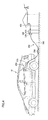
- Fig. 5 is a view showing an outline of an appearance of the charging cable unit.
- connector 310 when connected to inlet 250 of hybrid vehicle 10, connector 310 is fixed to inlet 250 by a lock mechanism (not shown).
- a lock release button 712 is provided in connector 310. When the user manipulates lock release button 712, connector 310 connected to inlet 250 can be separated from hybrid vehicle 10.
- hybrid vehicle. 10 is controlled so as to be put in the rest state when the power storage device mounted on hybrid vehicle 10 is charged. However, when hybrid vehicle. 10 moves for any reason, for example, possibly cable 340 is broken. Accordingly, in the first embodiment, the charging of the power storage device is stopped when the vehicle moves during the charging of the power storage device. The charging of the power storage device is resumed when the charging unit such as the cable is in a normal state.
- Fig. 6 is a block diagram for illustrating a configuration of the ECU of the first embodiment.
- Fig. 6 particularly shows the configuration relating to control of the charging of the power storage device.
- ECU 170 includes an estimation unit 501, a travel distance computing unit 502, a stopping determination unit 503, a diagnostic unit 504, a resuming determination unit 505, a command producing unit 506, a charging execution unit 507, a charging stopping unit 508, a charging resuming unit 509, a monitoring unit 510, a storage unit 511, and an output unit 512.
- Estimation unit 501 estimates that hybrid vehicle 10 is in the rest state based on the user operation in which hybrid vehicle 10 is controlled so as to be put in the rest state. Specifically, estimation unit 501 estimates that hybrid vehicle 10 is in the rest state when the user turns off start/stop switch280. Estimation unit 501 may estimate that hybrid vehicle 10 is in the rest state by detecting the user operation that activates the braking device or parking lock mechanism.
- travel distance computing unit 502 Based on the image from camera 260 and/or the detection values of various sensors, travel distance computing unit 502 performs the processing to calculate a vehicle travel distance.
- Stopping determination unit 503 determines whether a need for stopping the charging of the power storage device arises based on the vehicle travel distance calculated by travel distance computing unit 502. Stopping determination unit 503 sends the determination result to diagnostic unit 504 and command producing unit 506.
- Diagnostic unit 504 diagnoses the state of the charging unit including charging cable charging 300, inlet 250, and charger 240 based on signals CPLT and CNCT sent from charging cable charging 300, the detection value of voltage sensor 188 provided between charger 240 and inlet 250, and the detection values of voltage sensors 182 and 184 provided in charger 240.
- the "state of the charging unit” means the state relating to the supply of the electric power of the charging unit, and specifically the “state of the charging unit” means the presence or absence of the cable breakage, the connection state between connector 310 and inlet 250, and the like.
- Resuming determination unit 505 determines whether the charging of the power storage device can be resumed based on the diagnostic result of diagnostic unit 504. When the diagnostic result of diagnostic unit 504 indicates that the charging unit is normal, resuming determination unit 505 determines that the charging of the power storage device can be resumed. On the other hand, the diagnostic result of diagnostic unit 504 indicates that the charging unit is abnormal, resuming determination unit 505 determines that the charging of the power storage device cannot be resumed.
- Command producing unit 506 receives signals CPLT and CNCT to determine whether the vehicle can receive the electric power from the power supply. Command producing unit 506 receives the estimation result of estimation unit 501. When the vehicle can receive the electric power from the power supply while the vehicle is in the rest state, command producing unit 506 produces a command for operating charger 240 and sends the command to charging execution unit 507.
- Command producing unit 506 also receives the determination result of stopping determination unit 503. When stopping determination unit 503 determines that the need for stopping the charging of the power storage device arises, command producing unit 506 produces a command for stopping charger 240 and sends the command to charging execution unit 507 and charging stopping unit 508.
- Command producing unit 506 also receives the determination result of resuming determination unit 505. When resuming determination unit 505 determines that the charging of the power storage device can be resumed, command producing unit 506 produces a command for operating charger 240 and sends the command to charging resuming unit 509.
- Charging execution unit 507 receives the command for operating charger 240 from command producing unit 506. Charging execution unit 507 produces signals SIG1 and SIG2 in response to the command and sends signals SIG1 and SIG2 thus produced to charger 240. Charging execution unit 507 stops the production of signals SIG1 and SIG2 when receiving the command for stopping charger 240 from command producing unit 506.
- Charging stopping unit 508 receives the command for stopping charger 240 from command producing unit 506. Charging stopping unit 508 produces signal STP in response to the command and transmits signal STP thus produced to charger 240.
- Charging resuming unit 509 receives the command for operating charger 240 again from command producing unit 506. Charging resuming unit 509 produces signals SIG1 and SIG2 in response to the command and transmits signals SIG1 and SIG2 thus produced to charger 240.
- Monitoring unit 510 monitors the state of charger 240 based on signals SIG1, SIG2, and STP. Monitoring unit 510 produces information X indicating that the charging of the power storage device is stopped, when charging stopping unit 508 outputs signal STP. Monitoring unit 510 produces information Y indicating that the charging of the power storage device is resumed, when charging resuming unit 509 outputs signals SIG1 and SIG2.
- the pieces of information X and Y produced by monitoring unit 5 10 are stored in storage unit 511.
- Output unit 512 reads at least one of the pieces of information X and Y stored in storage unit 511 and outputs the read information to display device 270.
- Display device 270 displays the information from output unit 512.
- Fig. 7 is a flowchart for illustrating a charging starting processing of a power storage device performed by the ECU. The processing shown in the flowchart is called from a main routine and performed every predetermined time or when a predetermined condition holds.
- step S1 ECU 170 determines whether hybrid vehicle 10 can receive the electric power from power supply 402.
- command producing unit 506 determines that hybrid vehicle 10 can receive the electric power from power supply 402. In this case (YES in step S1), the processing goes to step S2.
- command producing unit 506 determines that hybrid vehicle 10 cannot receive the electric power from power supply 402. In this case (NO in step S1), the whole processing is ended.
- step S2 ECU 170 determines whether hybrid vehicle 10 is in the rest state. Specifically, estimation unit 501 estimates that the vehicle is in the rest state when start/stop switch 280 is in the off state. Command producing unit 506 determines whether hybrid vehicle 10 is in the rest state based on the estimation result of estimation unit 501.
- step S2 When command producing unit 506 determines that hybrid vehicle 10 is in the rest state (YES in step S2), the processing goes to step S3. On the other hand, when command producing unit 506 determines that hybrid vehicle 10 is not in the rest state (NO in step S2), the whole processing is ended.
- step S3 ECU 170 starts the charging of power storage device 150.
- command producing unit 506 produces the command for operating charger 240 and sends the command to charging execution unit 507.
- Charging execution unit 507 produces signals SIG1 and SIG2 in response to the command and transmits signals SIG1 and SIG2 thus produced to charger 240.
- Charger 240 starts the operation for charging power storage device 150 in response to signals SIG and SIG2.
- Fig. 8 is a flowchart for illustrating a charging processing of the first embodiment.
- the charging processing of Fig. 8 is performed subsequent to the processing of the flowchart of Fig. 7 .
- ECU 170 determines whether the charging of the power storage device is started.
- command producing unit 506 determines that the charging of the power storage device is started when the processing in step S3 of Fig. 7 is performed. In this case (YES in step S11), the processing goes to step S12.
- step S3 of Fig. 7 is not performed, command producing unit 506 determines that the charging of the power storage device is not started. In this case (NO in step S11), the whole processing is ended.
- ECU 170 detects the initial position of hybrid vehicle 10, that is, the position of hybrid vehicle 10 at the beginning of the charging of power storage device 150.
- travel distance computing unit 502 detects the initial position by obtaining the image from camera 260 at the beginning of the charging.
- travel distance computing unit 502 obtains the detection value from vehicle speed sensor 262 at the beginning of the charging.
- travel distance computing unit 502 detects that the current position of the vehicle is the initial position.
- the initial position detecting method there is no particular limitation to the initial position detecting method.
- step S13 ECU 170 determines whether the hybrid vehicle moves.
- travel distance computing unit 502 computes the travel distance of hybrid vehicle 10. Stopping determination unit 503 determines whether hybrid vehicle 10 moves based on the computed travel distance.
- Stopping determination unit 503 determines that the hybrid vehicle is stopped, when the travel distance of the hybrid vehicle is zero. In this case (NO in step S13), the processing goes to step S21. On the other hand, when the travel distance of the hybrid vehicle is not zero, stopping determination unit 503 determines that hybrid vehicle moves. In this case (YES in step S13), the processing goes to step S14.
- stopping determination unit 503 determines that the need for stopping the charging of the power storage device arises. Stopping determination unit 503 transmits the determination result to command producing unit 506. Command producing unit 506 produces the command for stopping charger 240 in response to the determination result of stopping determination unit 503, and the command producing unit 506 sends the command to charging execution unit 507 and charging stopping unit 508.
- Charging execution unit 507 stops the production of signals SIG1 and SIG2 in response to the command from command producing unit 506.
- Charging stopping unit 508 produces signal STP in response to the command from command producing unit 506.
- Charger 240 is stopped by signal STP. As a result, the charging of power storage device 150 is stopped.
- step S15 ECU 170 stores the information indicating that the charging of power storage device 150 is stopped.
- Monitoring unit 510 produces information X indicating that the charging of power storage device 150 is stopped in response to signal STP.
- Information X is stored in storage unit 511.
- step S16 ECU 170 diagnoses the state of the charging unit including charging cable unit 300, inlet 250, and charger 240.
- diagnostic unit 504 determines that charging cable unit 300 (connector 310) and the vehicle (inlet 250) are normally connected.
- diagnostic unit 504 detects the presence or absence of the abnormity of the charging pathway (electric power line pair 341 of the charging cable unit and the electric power line pair on the hybrid vehicle side) through which the electric power is sent from power supply 402 to charger 240 based on the detection values of voltage sensor 188, voltage sensor 182, and current sensor 184.
- the "abnormity" includes an earth fault and disconnection of any one of the two electric power lines, and the like.
- the abnormal connection of charging cable unit 300 (connector 310) and the vehicle (inlet 250) and the abnormal charging pathway correspond to the abnormal supply state of the electric power of the charging unit.
- An electric leakage detector may be provided in hybrid vehicle 10 or charging cable unit 300 in order to detect the electric leakage in the charging pathway.
- diagnostic unit 504 detects the presence or absence of the abnormity of the charging pathway based on the detection result of the electric leakage detector.
- step S17 ECU 170 determines whether the charging of the power storage device can be resumed. Specifically, when diagnostic unit 504 determines that the charging unit is in the normal state, resuming determination unit 505 determines that the charging of the power storage device can be resumed. In this case (YES in step S17), resuming determination unit 505 sends the determination result to command producing unit 506.
- command producing unit 506 produces the command for operating charger 240 and sends the command to charging resuming unit 509.
- Charging resuming unit 509 produces signals SIG1 and SIG2 in response to the command and transmits signals SIG1 and SING2 thus produced to charger 240.
- charger 240 is operated so as to charge power storage device 150. Therefore, the charging of powder storage device 150 is resumed (step S18).
- step S19 ECU 170 stores the information indicating that the charging of power storage device 150 is resumed. Specifically, the monitoring unit 510 produces information Y indicating that the charging of power storage device 150 is resumed in response to signals SIG1 and SIG2 from charging resuming unit 509. Information Y is stored in storage unit 511. When the processing in step S19 is ended, the whole processing is ended.
- step S17 when the diagnostic result of diagnostic unit 504 indicates the abnormity of the charging unit, resuming determination unit 505 determines that the charging of power storage device 150 cannot be resumed. In this case (NO in step S17), resuming determination unit 505 sends the determination result to command producing unit 506. In such cases, command producing unit 506 does not produce the command for operating charger 240. Accordingly, the charging of power storage device 150 remains stopped (step S20). When the processing in step S20 is ended, the whole processing is ended.
- step S13 when stopping determination unit 503 determines that hybrid vehicle 10 is stopped (NO in step S13), ECU 170 continues the charging of power storage device 150 (step S21). In step S22, ECU 170 determines whether the charging of power storage device 150 is completed.
- ECU 170 estimates the charging state of power storage device 150 based on the voltage, current, and temperature of power storage device 150. ECU 170 determines whether the charging of power storage device 150 is completed based on the estimated state. When ECU 170 determines that the charging of power storage device 150 is completed (YES in step S22), the whole processing is ended. On the other hand, when ECU 170 determines that the charging of power storage device 150 is not completed (NO in step S22), the processing is returned to step S13.
- the user operates the start/stop switch (see Fig. 2 ), the braking device, and the parking lock mechanism, and the like, whereby hybrid vehicle 10 is controlled so as to be put in rest state. Therefore, the breakages of cable 340 and hybrid vehicle 10 caused by running of hybrid vehicle 10 can be prevented.
- an external force acts on hybrid vehicle 10 due to a tow or a natural disaster such as an earthquake, possibly hybrid vehicle 10 moves without user operation. In such cases, possibly cable 340 and hybrid vehicle 10 are broken.
- ECU 170 discontinues the charging of power storage device 150.
- the charging of power storage device 150 is discontinued. Because the charging is discontinued when the abnormity is probably generated in the charging unit (charging cable unit 300, inlet 250, and charger 240) by the movement of the vehicle, a probability of the progress of the abnormal charging unit or a probability of generating another abnormity can be reduced.
- ECU 170 diagnoses the state of the charging unit after the charging of power storage device 150 is stopped. ECU 170 determines whether the charging of power storage device 150 can be resumed based on the diagnostic result. When ECU 170 determines that the charging of power storage device 150 can be resumed, ECU 170 resumes the charging of power storage device 150. ECU 170 determines whether the charging of power storage device 150 can be resumed, so that the user can be save the trouble to resume the charging.
- ECU 170 When ECU 170 detects that the abnormity exists in the charging unit, ECU 170 does not resume the charging of power storage device 150. In this case, the state in which the charging of power storage device 150 is stopped is continued. Therefore, the probability of the progress of the abnormal charging unit or the probability of generating another abnormity can be reduced.
- An entire configuration of a hybrid vehicle according to a second embodiment and a configuration of an electric system included in the hybrid vehicle of the second embodiment are similar to those of the first embodiment.
- a configuration of ECU according to the second embodiment is also similar to that of the first embodiment.
- Fig. 9 is a flowchart for illustrating a charging processing of the second embodiment.
- the charging processing of the second embodiment differs from that of the first embodiment in that processing in step S13A is performed instead of the processing in step S13. Because other pieces of processing in the flowchart of Fig. 9 are similar to the corresponding pieces of processing in the flowchart of Fig. 8 , the processing in step S13A will be described in detail.
- step S13A ECU 170 determines whether a variation (travel distance) in position of the hybrid vehicle is not lower than a predetermined threshold.
- travel distance computing unit 502 computes the travel distance of hybrid vehicle 10.
- Stopping determination unit 503 determines whether the travel distance of hybrid vehicle 10, computed by travel distance computing unit 502, is not lower than the threshold.
- the threshold is defined as the travel distance such that the user can easily recognize that the position of the hybrid vehicle differs from the initial position when the user confirms the position of the hybrid vehicle. Accordingly, although there is no particular limitation to the threshold, for example, the travel distance corresponding to one revolution of the hybrid vehicle wheel may be set to the threshold.
- step S14 When stopping determination unit 503 determines that the travel distance of hybrid vehicle 10 is equal to or more than the threshold (YES in step S13A), the processing goes to step S14. In this case, the charging of power storage device 150 is stopped. On the other hand, when stopping determination unit 503 determines that the travel distance of hybrid vehicle 10 is lower than the threshold (NO in step S13A), the processing goes to step S21. In this case, the charging of power storage device 150 is continued.
- the travel distance of hybrid vehicle 10 is calculated based on the detection value of the sensor, it is considered that the travel distance includes an error caused by a detection error of the sensor.
- the travel distance includes the error, for example, even if the hybrid vehicle does not actually move, possibly ECU 170 determines that hybrid vehicle 10 moves.
- ECU 170 determines that hybrid vehicle 10 moves, when the travel distance of hybrid vehicle 10 is equal to or more than the threshold. Therefore, the movement of the hybrid vehicle can be detected more securely during the charging of the power storage device.
- a hybrid vehicle according to a third embodiment is configured to be able to receive the electric power from the power supply while not being in contact with the power supply.
- the power storage device mounted on the hybrid vehicle is charged while the hybrid vehicle is in the rest state. Because an entire configuration of the hybrid vehicle of the third embodiment is similar to that of Fig. 1 , a configuration of a charging system for charging the power storage device will be described in detail below.
- Fig. 10 is an entire configuration diagram of a charging system of the third embodiment.
- hybrid vehicle 10 includes a secondary self-resonant coil 251, a secondary coil 252, charger 240, power storage device 150, a Power Control Unit (hereinafter also referred to as a "PCU") 201, MG 120, ECU 170, a communication device 190, and display device 270.
- PCU 201 includes converter 200 and inverters 210 any 220 (see Fig. 2 ).
- Secondary self-resonant coil 251 is provided in a lower portion of a vehicle body. However, secondary self-resonant coil 251 may be provided in an upper portion of the vehicle body when a power feeding device 420 is provided in the upper portion of the vehicle. Secondary self-resonant coil 251 is an LC resonant coil whose both ends are opened (non-connected), and secondary self-resonant coil 251 receives the electric power from power feeding device 420 by resonating with a primary self-resonant coil 424 (described later) of power feeding device 420 through an electromagnetic field.
- secondary self-resonant coil 251 based on a distance with primary self-resonant coil 424 of power feeding device 420 or a resonant frequency of primary self-resonant coil 424 and secondary self-resonant coil 251, the number of turns is properly set such that a Q value (for example, Q > 100) indicating resonant strength between primary self-resonant coil 424 and secondary self-resonant coil 251 and ⁇ indicating a degree of coupling of primary self-resonant coil 424 and secondary self-resonant coil 251 increase.
- a Q value for example, Q > 100
- Secondary coil 252 is provided in coaxial with secondary self-resonant coil 251, and secondary coil 252 can magnetically be coupled to secondary self-resonant coil 251 by electromagnetic induction. Secondary coil 252 takes out the electric power, received by secondary self-resonant coil 251, by the electromagnetic induction to output the electric power to charger 240.
- Charger 240 converts the alternating-current power taken out by secondary coil 252 into the direct-current power, and charger 240 converts voltage of the direct-current power into a voltage level of power storage device 150.
- ECU 170 controls charger 240.
- Secondary self-resonant coil 251 and secondary coil 252 constitute a power receiving unit in order to receive the electric power from power supply 402 in the noncontact manner.
- Secondary self-resonant coil 251, secondary coil 252, and charger 240 constitute the charging unit of the present invention.
- Communication device 190 is a communication interface that conducts wireless communication with power feeding device 420 outside the vehicle.
- Power feeding device 420 includes power supply 402, a high-frequency power driver 421, a primary coil 422, primary self-resonant coil 424, communication device, 426, and an ECU 260.
- High-frequency power driver 421 converts the electric power received from power supply 402 into a high-frequency power and supplies the converted high-frequency power to primary coil 422.
- a frequency of the high-frequency electric power produced by high-frequency power driver 421 ranges from ane megahertz to over ten megahertz.
- Primary coil 422 is provided in coaxial with primary self-resanant coil 424, and primary coil 422 can magnetically be coupled to primary self-resonant coil 424 by the electromagnetic induction.
- Primary coil 422 feeds the high-frequency power, supplied from high-frequency power driver 421, to primary self-resonant coil 424 by the electromagnetic induction.
- Primary self-resonant coil 424 is provided close to the ground. However, primary self-resonant coil 424 may be provided in the upper portion or side portion of the vehicle when the electric power is fed from above hybrid vehicle 10. Primary self-resonant coil 424 is also an LC resonant coil whose both ends are opened (non-connected) and sends the electric power to hybrid vehicle 10 through secondary self-resonant coil 251 of hybrid vehicle 10 and the electromagnetic field.
- the number of turns is properly set such that a Q value (for example, Q > 100), the degree of coupling ⁇ and the like increase based on a distance with secondary self-resonant coil 251 of hybrid vehicle 10 or the resonant frequency of primary self-resonant coil 424 and secondary self-resonant coil 251.
- a Q value for example, Q > 100
- the degree of coupling ⁇ and the like increase based on a distance with secondary self-resonant coil 251 of hybrid vehicle 10 or the resonant frequency of primary self-resonant coil 424 and secondary self-resonant coil 251.
- Communication device 426 is a communication interface that conducts wireless communication with hybrid vehicle 10 of the power feeding destination.
- ECU 428 controls high-frequency power driver 421 such that the power receiving voltage of hybrid vehicle 10 becomes the target value.
- primary-side voltage output voltage from power feeding device 420
- secondary-side voltage power receiving voltage of hybrid vehicle 10
- a range where the secondary-side voltage is more than a threshold is previously defined as a power receivable range 430.
- the threshold is previously defined in consideration of operation efficiency of charger 240.
- a relationship of Fig. 11 is previously stored in ECU 170.
- ECU 170 determines whether secondary self-resonant coil 251 exists within power receivable rang 430 based on the relationship of Fig. 11 and the power receiving voltage of hybrid vehicle 10.
- the power receiving voltage of hybrid vehicle 10 is detected by the voltage sensor.
- ECU 170 detects the position of secondary self-resonant coil 251.
- secondary self-resonant coil 251 exists within power receivable range 430
- ECU 170 determines that the charging of power storage device 150 can be resumed.
- secondary self-resonant coil 251 is out of power receivable range 430
- ECU 170 determines that the charging of power storage device 150 cannot be resumed.
- Fig. 12 is a block diagram for illustrating a configuration of the ECU of the third embodiment. Referring to Figs. 12 and 6 , the ECU of the third embodiment differs from the ECU of the first embodiment in the following points.
- the detection value of the sensor provided in the charging cable unit is not fed into travel distance computing unit 502. Similarly, the signal is not fed into command producing unit 506 from the charging cable unit.
- the detection value of voltage sensor 189 is fed into diagnostic unit 504 in order to detect the power receiving voltage of hybrid vehicle 10. Diagnostic unit 504 diagnoses the state of the charging unit based on the detection value of voltage sensor 189 and the relationship of Fig. 11 .
- Charging execution unit 507 and charging resuming unit 509 produce signals SIG in order to operate charger 240 and output signals SIG to charger 240.
- ECU of the third embodiment are similar to those of the corresponding portions of ECU of the first embodiment.
- Diagnostic unit 504 detects whether the position of secondary self-resonant coil 251 exists within the power receivable range based on the detection value of voltage sensor 189 and the relationship of Fig. 11 . When the detection value of voltage sensor 189 is more than the threshold, diagnostic unit 504 detects that the position of secondary self-resonant coil 251 exists within the power receivable range, and diagnostic unit 504 determines that the electric power is normally supplied by the charging unit.
- diagnostic unit 504 detects that the position of secondary self-resonant coil 251 is out of the power receivable range, and diagnostic unit 504 determines that the electric power is abnormally supplied by the charging unit.
- the user can be saved the trouble to resume the charging.
- the present invention can be applied to the vehicle an which the power storage device is mounted.
- the hybrid vehicle on which the internal combustion engine, the electric motor, and the power storage device are mounted is described as an example of the vehicle on which the electric motor generating the running driving force and the power storage device, in which the electric power supplied to the electric motor is stored, are mounted.
- the present invention can also be applied to the electric vehicle and the fuel-cell vehicle.
Landscapes
- Engineering & Computer Science (AREA)
- Power Engineering (AREA)
- Transportation (AREA)
- Mechanical Engineering (AREA)
- Sustainable Energy (AREA)
- Sustainable Development (AREA)
- Life Sciences & Earth Sciences (AREA)
- Chemical & Material Sciences (AREA)
- Combustion & Propulsion (AREA)
- Computer Networks & Wireless Communication (AREA)
- Electric Propulsion And Braking For Vehicles (AREA)
- Charge And Discharge Circuits For Batteries Or The Like (AREA)
- Secondary Cells (AREA)
- Current-Collector Devices For Electrically Propelled Vehicles (AREA)
Abstract
Description
- The present invention relates to a charging system, a vehicle, and a charging system control method, and particularly to a technology for charging a power storage device mounted on the vehicle by a power supply provided outside the vehicle.
- A vehicle such as an electric vehicle, a hybrid vehicle, and a fuel cell vehicle recently draws public attention as an eco-friendly vehicle. The vehicle includes an electric motor that generates a running driving force and a power storage device in which an electric power supplied to the electric motor is stored.
- There has been a configuration in which the power storage device mounted on the vehicle is charged by a power supply provided outside the vehicle (hereinafter referred to as an "external power supply"). For example, Japanese Patent Laying-Open No.
O5-328619 -
- Patent Document 1: Japanese Patent Laying-Open No.
05-328619 - Patent Document 2: Japanese Patent Laying-Open No.
06-105408 - Patent Document 3: National Publication No.
08-505277 - A cable is possibly broken when a vehicle moves while the vehicle remains connected to the cable. According to Japanese Patent Laying-Open No.
05-328619 05-328619 - An object of the present invention is to provide a technology for being able to save the user the trouble when the charging of the vehicle is resumed after the charging is temporarily stopped.
- In accordance with an aspect of the present invention, a charging system for charging a power storage device mounted on a vehicle by a power supply provided outside the vehicle includes: a charging unit configured to be able to charge the power storage device by an electric power supplied from the power supply when the vehicle is in a rest state; and a charging control unit configured to control the charging unit. The charging control unit includes a charging execution unit, a detection unit, a charging stopping unit, a diagnostic unit, a determination unit, and a charging resuming unit. The charging execution unit is configured to operate the charging unit in order to charge the power storage device. The detection unit is configured to detect a change in position of the vehicle. The charging stopping unit is configured to cause the charging unit to stop the charging of the power storage device, when the detection unit detects the change in position of the vehicle from a starting position of the charging of the power storage device while the charging unit charges the power storage device. The diagnostic unit is configured to diagnose a state of the charging unit associated with a supply of the electric power, when the charging stopping unit stops the charging of the power storage device. The determination unit is configured to determine whether the charging unit is able to resume the charging of the power storage device based on a diagnostic result of the diagnostic unit. The charging resuming unit is configured to cause the charging unit to resume the charging of the power storage device, when the determination unit determines that the operation of the charging unit is able to be resumed.
- Preferably the vehicle includes an operating device for controlling the vehicle so as to put the vehicle in the rest state according to an operation of an operator. The charging control unit further includes an estimation unit configured to estimate that the vehicle is in the rest state, based on the operation of the operating device by the operator. The charging execution unit is configured to cause the charging unit to start the charging of the power storage device, when the estimation unit estimates that the vehicle is in the rest state.
- Preferably, the charging control unit further includes an information producing unit and a storage unit. The information producing unit is configured to produce first information and second information, the first information indicates that the charging stopping unit stops the charging of the power storage device, and the second information indicates that the charging resuming unit resumes the charging of the power storage device. The storage unit is configured to store the first information and the second information therein.
- Preferably, the charging unit includes: a cable for transferring the electric power from the power supply to the vehicle; an inlet provided in the vehicle to be able to be connected to the cable; and a charger. The charger is provided in the vehicle, and the charger is configured to supply the electric power fed into the inlet to the power storage device under the control of the charging execution unit and the charging resuming unit while stopping the supply of the electric power to the power storage device under the control of the charging stopping unit. The diagnostic unit is configured to diagnose the state of the charging unit by detecting at least a state of the cable and a connection state between the cable and the inlet.
- Preferably, the charging unit includes a power receiving unit and a charger. The power receiving unit is provided in the vehicle, and the power receiving unit is configured to be able to receive the electric power in a non-contact manner from the power supply within a predetermined range. The charger is provided in the vehicle, and the charger is configured to supply the electric power received by the power receiving unit to the power storage device under the control of the charging execution unit and the charging resuming unit while stopping the supply of the electric power to the power storage device under the control of the charging stopping unit. The diagnostic unit is configured to diagnose the state of the charging unit by detecting whether a position of the power receiving unit falls within a predetermined range.
- In accordance with another aspect of the present invention, a vehicle includes a power storage device; a charging unit configured to be able to charge the power storage device by an electric power from supplied from the power supply when the vehicle is in a rest state; and a charging control unit configured to control the charging unit. The charging control unit includes a charging execution unit, a detection unit, a charging stopping unit, a diagnostic unit, a determination unit, and a charging resuming unit. The charging execution unit is configured to operate the charging unit in order to charge the power storage device. The detection unit is configured to detect a change in position of the vehicle. The charging stopping unit is configured to cause the charging unit to stop a charging of the power storage device when the detection unit detects the change in position of the vehicle from a starting position of the charging of the power storage device while the charging unit charges the power storage device. The diagnostic unit is configured to diagnose a state of the charging unit associated with a supply of the electric power, when the charging stopping unit stops the charging of the power storage device. The determination unit is configured to determine whether an operation of the charging unit is able to be resumed based on a diagnostic result of the diagnostic unit. The charging resuming unit is configured to cause the charging unit to resume the charging of the power storage device, when the determination unit determines that the operation of the charging unit is able to be resumed.
- In accordance with still another aspect of the present invention, a charging system control method is a method for controlling charging system for charging a power storage device mounted on a vehicle by a power supply provided outside the vehicle. The charging system includes: a charging unit configured to be able to charge the power storage device by an electric power supplied from the power supply when the vehicle is in a rest state; and a charging control unit configured to control the charging unit. The charging system control method includes the steps of: operating the charging unit in order to charge the power storage device; determining whether a position of the vehicle changes from a starting position of a charging of the power storage device while the charging unit charges the power storage device; causing the charging unit to stop the charging of the power storage device when the determination is made that the position of the vehicle changes from the starting position of the charging of the power storage device; diagnosing a state of the charging unit associated with a supply of the electric power, when the charging of the power storage device is stopped; determining whether an operation of the charging unit is able to be resumed based on a diagnostic result of the diagnostic step; and causing the charging unit to resume the charging of the power device, when the determination is made that the operation of the charging unit is able to be resumed.
- According to the present invention, the user can be saved the trouble when the charging of the vehicle is resumed after the charging is temporarily stopped.
-
-
Fig. 1 its an entire block diagram of a hybrid vehicle that is of an example of a vehicle according to an embodiment of the present invention. -
Fig. 2 is an entire configuration diagram showing an electric system of a hybrid vehicle according to a first embodiment. -
Fig. 3 is a diagram for illustrating a configuration in which the hybrid vehicle of the first embodiment is charged by an external power supply. -
Fig. 4 is a view for illustrating an example of the external power supply that can supply an electric power to the hybrid vehicle. -
Fig. 5 is a view showing an outline of an appearance of a charging cable unit. -
Fig. 6 is a block diagram for illustrating a configuration of an ECU of the first embodiment. -
Fig. 7 is a flowchart for illustrating a charging starting processing of a power storage device performed by the ECU. -
Fig. 8 is a flowchart for illustrating a charging processing of the first embodiment. -
Fig. 9 is a flowchart for illustrating a charging processing according to a second embodiment. -
Fig. 10 is an entire configuration diagram of a charging system according to a third embodiment. -
Fig. 11 is a view showing a relationship between a distance of a power feeding device and a hybrid vehicle and a power receiving voltage (secondary-side voltage) of the hybrid vehicle. -
Fig. 12 is a block diagram for illustrating a configuration of an ECU of the third embodiment. - Hereinafter, embodiments of the present invention will be described in detail with reference to the drawings. In the drawings, the same or equivalent component is designated by the same reference character, and a description thereof will not be repeated.
-
Fig. 1 is an entire block diagram showing a hybrid vehicle that is of an example of a vehicle according to an embodiment of the present invention. Referring to Fug. 1, ahybrid vehicle 10 includes anengine 100, a Motor Generator (MG) 110, anMG 120, apower split mechanism 130, aspeed reducer 140, apower storage device 150, adriver wheel 160, and an Electronic Control Unit (ECU) 170. -
Engine 100,MG 110, andMG 120 are coupled topower split mechanism 130. Hybrid vehicle. 10 runs by a driving force from at least one ofengine 100 andMG 120.Power split mechanism 130 divides power generated byengine 100 into two pathways. That is, one of the pathways is one that transmitted to drivewheel 160 throughspeed reducer 140, and the other pathway is one that is transmitted toMG 110. -
Engine 100 is an internal combustion engine that combusts fuel such as gasoline to generate the power. -
MG 110 is an alternating-current rotating electrical machine and, for example,MG 110 is a three-phase alternating-current synchronous electric motor including a U-phase coil, a V-phase coil, and a W-phase coil.MG 110 generates an electric power using the power ofengine 100, which is divided bypower split mechanism 130. For example,engine 100 is started up to generate the electric power withMG 110 when a charging state (hereinafter also referred to as "SOC (State Of Charge") ofpower storage device 150 becomes lower than a predetermined value. The electric power generated byMG 110 is converted from an alternating current into a direct current by an inverter (described later). A voltage of the direct-current power from the inverter is adjusted by a converter (described later), and the direct-current power is stored inpower storage device 150. -
MG 120 is an alternating-current rotating electric machine and, for example,MG 120 is an alternating-current synchronous electric motor includes a U-phase coil, a V-phase coil, and a W-phase coil.MG 120 generates a driving force using at least one of the electric power stored inpower storage device 150 and the electric power generated byMG 110. The driving force ofMG 120 is transmitted to drivewheel 160 viaspeed reducer 140. Therefore,MG 120assists engine 100, or the vehicle runs by the driving force fromMG 120. InFig. 1 ,drive wheel 160 is shown as a front wheel. However, instead of the front wheel or along with the front wheel, the rear wheel may be driven. - During braking of the vehicle,
MG 120 is driven bydrive wheel 160 throughspeed reducer 140, andMG 120 acts as a generator. Therefore,MG 120 acts a regeneration brake that converts the braking energy into the electric power. The electric power generated byMG 120 is stored inpower storage device 150. -
Power split mechanism 130 includes a planet gear, and the planet gear includes a sun gear, a pinion gear, a carrier, and a ring gear. The pinion gear engages the sun gear and the ring gear. The carrier supports the pinion gear so that the pinion gear can rotate on its own axis, and is coupled to a crankshaft ofEngine 100. The sun gear is coupled to a rotating shaft ofMG 110. The ring gear is coupled to a rotating shaft ofMG 120 andspeed reducer 140. -
Engine 100,MG 110, andMG 120 are coupled to each other whilepower split mechanism 130 including the planet gear is interposed therebetween, whereby the rotating speeds ofengine 100,MG 110 andMG 120 become a relationship connected by a straight line in a nomographic diagram. -
Power storage device 150 is a chargeable-dischargeable direct-current power supply. For example,power storage device 150 includes a secondary battery such as a nickel-hydrogen secondary battery and a lithium-ion secondary battery. In addition to the electric powers generated byMG 110 andMG 120, as described later, an electric power supplied from a power supply outside the vehicle is stored inpower storage device 150. - A large-capacity capacitor may be used as
power storage device 150. Any power storage device may be used aspower storage device 150 as long as the power storage device is a power buffer in which the electric powers generated byMG 110 andMG 120 and the electric power supplied from a power supply outside the vehicle can temporarily be stored while the stored electric powers are supplied toMG 120. There is no particular limitation to the number of power storage devices mounted onhybrid vehicle 10. Accordingly, a plurality of power storage devices may be mounted onhybrid vehicle 10. Capacities of the plurality of power storage devices may actually be equal to or different from one another. -
ECU 170 controlsengine 100,MG 110, andMG 120. It should be noted thatECU 170 may be divided into a plurality of ECUs respectively serving several functions. - A configuration for storing
power storage device 150 mounted onhybrid vehicle 10 will be described below in each embodiment. -
Fig. 2 is an entire configuration diagram showing an electric system of a hybrid vehicle according to a first embodiment. Referring toFig. 2 ,hybrid vehicle 10 includes aconverter 200, aninverter 210, aninverter 220, a System Main Relay (SMR) 230, acharger 240, aninlet 250, aCamera 260, avehicle speed sensor 262, awheel speed sensor 264, anacceleration sensor 266, adisplay device 270, and a start/stop twitch 280. -
Converter 200 includes a reactor, two npn-type transistors, and two diodes. In the reactor, one end is connected onto a positive electrode orpower storage device 150, and the other end is connected to a connection node of the two npn-type transistors. The two npn-type transistors are connected in series, and the diode is connected in antiparallel to each npn-type transistor. - For example, an Insulated Gate Bipolar Transistor (IGBT) can be used as the npn-type transistor. A power switching element such as a power Metal Oxide Semiconductor Field-Effect Transistor (MOSFET) may be used instead of the npn-type transistor.
-
Converter 200 boosts a voltage supplied frompower storage device 150 when the electric power discharged frompower storage device 150 is supplied toMG 110 orMG 120. On the other hand,converter 200 performs a step-down operation whenpower storage device 150 is charged by the electric power generated byMG 110 orMG 120. - Each of
inverters - A connection point of the two npn-type transistors in each arm of
inverter 210 is connected to an end portion corresponding to each arm, and the end portion is different from aneutral point 112 of a stator coil ofMG 110. A connection point of the two npn-type transistors in each arm ofinverter 220 is connected to an end portion corresponding to each arm, and the end portion is different from aneutral point 122 of a stator coil ofMG 120. -
Inverter 210 converts the direct current supplied frompower storage device 150 into the alternating current and supplies the alternating current toMG 110.Inverter 210 also converts the alternating current generated byMG 110 into the direct current.Inverter 220 converts the direct current supplied frompower storage device 150 into the alternating current and supplies the alternating current toMG 120.Inverter 220 also converts the alternating current generated byMG 120 into the direct current. -
ECU 170controls converter 200,inverter 210, andinverter 220. -
SMR 230 is provided betweenpower storage device 150 andcharger 240.SMR 230 switches between an opened state and a closed state under the control ofECU 170. WhenSMR 230 is in the opened state,power storage device 150 is electrically cut off fromconverter 200 andcharger 240. WhenSMR 230 is in the closed state,power storage device 150 is electrically connected toconverter 200 andcharger 240. -
Inlet 250 is provided in hybrid vehicle. 10 in order to receive the electric power supplied from the external power supply.Inlet 250 its configured to be able to be connected to a cable unit (not shown) through which the electric power is sent from external power supply.Inlet 250 is connected to the external power supply via the cable unit, wherebyinlet 250 receives the electric power supplied from the external power supply. -
Charger 240 is connected betweenpower storage device 150 andconverter 200.Charger 240 converts the alternating-current power fed intoinlet 250 into the direct-current power and supplies the direct-current power topower storage device 150. The direct-current power is supplied fromcharger 240 topower storage device 150, thereby chargingpower storage device 150. -
Camera 260 takes an image of a neighborhood ofhybrid vehicle 10. The image taken bycamera 260 is sent toECU 170. -
Vehicle speed sensor 262 detects a speed SV ofhybrid vehicle 10 and outputs the detection value toECU 170.Wheel speed sensor 264 detects a speed SW of a wheel (for example,drive wheel 160 ofFig. 1 ) ofhybrid vehicle 10 and outputs the detection value toECU 170.Acceleration sensor 266 detects acceleration ofhybrid vehicle 10 and outputs the detection value toECU 170. -
Display device 270 displays various kinds of information under the control ofECU 170. For example,display device 270 displays the image taken bycamera 260. For example,display device 270 displays processing result ofECU 170. - Start/
stop switch 280 is manipulated by a user in order to start up and stop the electric system ofFig. 2 . When start/stop switch 280 is turned on,ECU 170 starts up the electric system in order to causehybrid vehicle 10 to be able to run. On the other hand, when start/stop switch 280 is turned off,ECU 170controls SMR 230 so as to putSMR 230 in the opened state while stoppingconverter 200 andinverters - Although not shown in
Figs. 1 and2 ,hybrid vehicle 10 further includes devices, such as a braking device and a parking lock mechanism, which fixhybrid vehicle 10 into the rest state. The devices, such as the braking device, which fixhybrid vehicle 10 into the rest state and start/stop switch 280 correspond to a state control device that controlshybrid vehicle 10 so as to put hybrid vehicle. 10 in the rest state by operation of the user (operator). -
Fig. 3 is a view for illustrating a configuration in which the hybrid vehicle of the first embodiment is charged by an external power supply. Referring toFig. 3 ,charger 240 includes an AC/DC conversion circuit 242, a DC/AC conversion circuit 244, aninsulation transformer 246, and arectifying circuit 248. - AC/
DC conversion circuit 242 converts the alternating-current power into the direct-current power based on adriving signal SIG 1 fromECU 170. AC/DC conversion circuit 242 also acts as a boosting chopper circuit that boosts the voltage with the coil as the reactor. Based on a driving signal SIG2 fromECU 170, DC/AC conversion circuit 244 converts the direct-current power into the high-frequency alternating-current power and outputs the high-frequency alternating-current power toinsulation transformer 246. -
Insulation transformer 246 includes a core made of a magnetic material, a primary coil, and a secondary coil. The primary coil and the secondary coil are wound on the core. The primary coil and the secondary coil are electrically insulated from each other, and the primary coil and the secondary coil are connected to DC/AC conversion circuit 244 and rectifyingcircuit 248, respectively.Insulation transformer 246 converts the high-frequency alternating-current power received from DC/AC conversion circuit 244 into the alternating-current power having a voltage level according to a winding ratio of the primary coil and the secondary coil, andinsulation transformer 246 outputs the converted alternating-current power to rectifyingcircuit 248. Rectifyingcircuit 248 rectifies the alternating-current power output frominsulation transformer 246 into the direct-current power. - A
voltage sensor 182 detects a voltage (voltage between terminals of smoothing capacitor) between AC/DC conversion circuit 242 and DC/AC conversion circuit 244, and a signal indicating the detection result is fed intoECU 170. Acurrent sensor 184 detects the output current ofcharger 240, and a signal indicating the detection result is fed intoECU 170. -
ECU 170 produces the driving signal SIG1 and SIG2 to output the driving signal SIG1 and SIG2 to charger 240, whenpower storage device 150 is charged by apower supply 402 outside the vehicle. On the other hand, when the charging ofpower storage device 150 is stopped,ECU 170 produces a stopping signal STP in order to stopcharger 240 and outputs the stopping signal STP tocharger 240. AC/DC conversion circuit 242 and DC/AC conversion circuit 244 are stopped by stopping signal STP. -
ECU 170 has not only the function of controllingcharger 240 but also a function of detecting failure ofcharger 240. The failure ofcharger 240 is detected when the voltage detected byvoltage censor 182 and/or the current detected bycurrent sensor 184 is not lower than a threshold. - A charging
cable unit 300 is used to couplehybrid vehicle 10 andpower supply 402. Chargingcable unit 300 includes aconnector 310, aplug 320, a Charging Circuit Interrupt Device (CCID) 330, acable 340, anacceleration sensor 350, and astrain gauge 360.Cable 340 includes an electricpower line pair 341, aground line 342, andsignal lines 343 to 345. -
Connector 310 is connected toinlet 250 provided inhybrid vehicle 10.Switch 312 is provided inconnector 310. Whenconnector 310 is connected toinlet 250,switch 312 becomes a closed state while a signal CNCT is fed intoECU 170. Signal CNCT indicates the state in whichconnector 310 is connected toinlet 250. -
Plug 320 is connected to anoutlet 400 to which the alternating-current power is supplied frompower supply 402. For example,outlet 400 is provided in a charging station. -
CCID 330 includes arelay 332 and acontrol pilot circuit 334. A pathway through which the electric power is supplied tohybrid vehicle 10 frompower supply 402outside hybrid vehicle 10 is cut off whenrelay 332 is in the opened state. The electric power can be supplied tohybrid vehicle 10 frompower supply 402 whenrelay 332 is in the closed state.Connector 310 is connected toinlet 250, wherebyECU 170 controls relay 332. - When
plug 320 is connected tooutlet 400,control pilot circuit 334 is operated by the electric power supplied frompower supply 402.Control pilot circuit 334 produces a pilot signal CPLT. Pilot signal CPLT is transmitted viasignal line 343 toECU 170 of the vehicle. -
Control pilot circuit 334 oscillates pilot signal CPLT with a specified duty cycle (ratio of a pulse width to an oscillation period). The duty cycle is set based on a rated current that can be supplied frompower supply 402 to the vehicle through chargingcable unit 300. The rated current is defined in each cable (electric power line). Because the rated current depends on a kind of the cable, the duty cycle of pilot signal CPLT also depends on the kind of the cable.ECU 170 can detect the rated current, which can be supplied to the vehicle frompower supply 402 through chargingcable unit 300, by detecting the duty cycle of pilot signal CPLT. - The alternating-current voltage of
power supply 402 is detected by avoltage sensor 188 provided inhybrid vehicle 10. The detected voltage is transmitted toECU 170. -
Acceleration sensor 350 detects acceleration ofconnector 310, which is caused by the movement ofconnector 310, andacceleration sensor 350 sends the detection value toECU 170. The detection value ofacceleration sensor 350 is sent toECU 170 viasignal line 344.Strain gauge 360 detects tension acting oncable 340 and sends the detection value toECU 170. The detection value ofstrain gauge 360 is sent toECU 170 viasignal line 345. - During the charging of
power storage device 150,SMR 230 and relay 332 ofCCID 330 are closed, andcharger 240 is operated such that the electric power is supplied frompower supply 402 topower storage device 150. In the first embodiment, whether a position ofhybrid vehicle 10 changes from a position in which the charging is started (hereinafter referred to as an "initial position") is detected during the charging ofpower storage device 150. At least one ofcamera 260,vehicle speed sensor 262,wheel speed sensor 264,acceleration sensor 266,acceleration sensor 350, andstrain gauge 360 is used in order to detect the change in position ofhybrid vehicle 10. However, from the viewpoint of detection accuracy, at least two of the above-described devices are preferably used in order to detect the change in position of the vehicle. - As used herein, the "change in position" includes movement of the vehicle in a traveling direction (forward direction and backward direction) of the vehicle, movement of the vehicle in a right and left direction with respect to the traveling direction of the vehicle, vibration of the vehicle, and inclination of the vehicle.
- An example of processing for detecting the change in position of the vehicle will be described below.
Camera 260 takes the image of the neighborhood of the vehicle when the charging ofpower storage device 150 is started.ECU 170 obtains the image data fromcamera 260, and the image data is stored inECU 170.Camera 260 takes the image of the neighborhood of the vehicle at constant period and outputs the image data toECU 170.ECU 170 compares the image obtained fromcamera 260 and a previously-stored image.ECU 170 detects the change in position ofhybrid vehicle 10 based on the comparison result.ECU 170 computes an amount of change in position ofhybrid vehicle 10. - Because the vehicle is in the rest state at the beginning of the charging, the detection value of vehicle speed sensor 262 (or wheel speed sensor 264) becomes a value indicating a speed of zero. When the vehicle travels forward or backward, the detection value of the sensor changes.
ECU 170 detects the change in position ofhybrid vehicle 10 based on the detection value ofvehicle speed sensor 262.ECU 170 computes the amount of change in position ofhybrid vehicle 10 based on the detection value. - When hybrid vehicle. 10 moves during the charging of
power storage device 150,cable 340 moves andconnector 310 connected toinlet 250 moves.Acceleration sensor 350 detects the acceleration ofconnector 310. Therefore, the movement of the vehicle can be detected. Because the tension acting oncable 340 changes by the movement ofcable 340, the detection value ofstrain gauge 360 also changes. Accordingly, the movement of the vehicle can be detected based on the detection value ofstrain gauge 360. - The vibration or inclination of the vehicle can be detected by
acceleration sensor 266. For example, when the vehicle vibrates, the acceleration in the vibration direction is detected byacceleration sensor 266. When the vehicle inclines, for example, a component of gravitational acceleration in the inclination direction of the vehicle is detected byacceleration sensor 266. -
Fig. 4 is a view for illustrating an example of the external power supply that can supply the electric power to the hybrid vehicle. Referring toFig. 4 , a chargingstation 410 is a facility that supplies the electric power tohybrid vehicle 10. For example, chargingstation 410 is installed close to a parking space forhybrid vehicle 10. -
Charging station 410 includes anoutlet 400.Outlet 400 is connected topower supply 402. Typically,power supply 402 supplies the electric power from a system power supply. Alternatively,power supply 402 may supply the electric power generated by a generator (e.g., a solar battery panel).Power supply 402 may supply the electric power output from the power storage device in which the electric power generated by the generator is stored. -
Connector 310 provided at one end ofcable 340 is connected toinlet 250 provided inhybrid vehicle 10. Plug 320 provided at the other end ofcable 340 is connected tooutlet 400 provided in chargingstation 410. -
Fig. 5 is a view showing an outline of an appearance of the charging cable unit. Referring toFig. 5 , when connected toinlet 250 ofhybrid vehicle 10,connector 310 is fixed toinlet 250 by a lock mechanism (not shown). Alock release button 712 is provided inconnector 310. When the user manipulateslock release button 712,connector 310 connected toinlet 250 can be separated fromhybrid vehicle 10. - Referring back to
Fig. 4 , hybrid vehicle. 10 is controlled so as to be put in the rest state when the power storage device mounted onhybrid vehicle 10 is charged. However, when hybrid vehicle. 10 moves for any reason, for example, possiblycable 340 is broken. Accordingly, in the first embodiment, the charging of the power storage device is stopped when the vehicle moves during the charging of the power storage device. The charging of the power storage device is resumed when the charging unit such as the cable is in a normal state. -
Fig. 6 is a block diagram for illustrating a configuration of the ECU of the first embodiment.Fig. 6 particularly shows the configuration relating to control of the charging of the power storage device. Referring toFig. 6 ,ECU 170 includes anestimation unit 501, a traveldistance computing unit 502, a stoppingdetermination unit 503, adiagnostic unit 504, a resumingdetermination unit 505, acommand producing unit 506, a chargingexecution unit 507, acharging stopping unit 508, acharging resuming unit 509, amonitoring unit 510, astorage unit 511, and anoutput unit 512. -
Estimation unit 501 estimates thathybrid vehicle 10 is in the rest state based on the user operation in whichhybrid vehicle 10 is controlled so as to be put in the rest state. Specifically,estimation unit 501 estimates thathybrid vehicle 10 is in the rest state when the user turns off start/stop switch280.Estimation unit 501 may estimate thathybrid vehicle 10 is in the rest state by detecting the user operation that activates the braking device or parking lock mechanism. - Based on the image from
camera 260 and/or the detection values of various sensors, traveldistance computing unit 502 performs the processing to calculate a vehicle travel distance. - Stopping
determination unit 503 determines whether a need for stopping the charging of the power storage device arises based on the vehicle travel distance calculated by traveldistance computing unit 502. Stoppingdetermination unit 503 sends the determination result todiagnostic unit 504 andcommand producing unit 506. -
Diagnostic unit 504 diagnoses the state of the charging unit including charging cable charging 300,inlet 250, andcharger 240 based on signals CPLT and CNCT sent from charging cable charging 300, the detection value ofvoltage sensor 188 provided betweencharger 240 andinlet 250, and the detection values ofvoltage sensors charger 240. As used herein, the "state of the charging unit" means the state relating to the supply of the electric power of the charging unit, and specifically the "state of the charging unit" means the presence or absence of the cable breakage, the connection state betweenconnector 310 andinlet 250, and the like. - Resuming
determination unit 505 determines whether the charging of the power storage device can be resumed based on the diagnostic result ofdiagnostic unit 504. When the diagnostic result ofdiagnostic unit 504 indicates that the charging unit is normal, resumingdetermination unit 505 determines that the charging of the power storage device can be resumed. On the other hand, the diagnostic result ofdiagnostic unit 504 indicates that the charging unit is abnormal, resumingdetermination unit 505 determines that the charging of the power storage device cannot be resumed. -
Command producing unit 506 receives signals CPLT and CNCT to determine whether the vehicle can receive the electric power from the power supply.Command producing unit 506 receives the estimation result ofestimation unit 501. When the vehicle can receive the electric power from the power supply while the vehicle is in the rest state,command producing unit 506 produces a command for operatingcharger 240 and sends the command to chargingexecution unit 507. -
Command producing unit 506 also receives the determination result of stoppingdetermination unit 503. When stoppingdetermination unit 503 determines that the need for stopping the charging of the power storage device arises,command producing unit 506 produces a command for stoppingcharger 240 and sends the command to chargingexecution unit 507 and charging stoppingunit 508. -
Command producing unit 506 also receives the determination result of resumingdetermination unit 505. When resumingdetermination unit 505 determines that the charging of the power storage device can be resumed,command producing unit 506 produces a command for operatingcharger 240 and sends the command to charging resumingunit 509. -
Charging execution unit 507 receives the command for operatingcharger 240 fromcommand producing unit 506.Charging execution unit 507 produces signals SIG1 and SIG2 in response to the command and sends signals SIG1 and SIG2 thus produced tocharger 240.Charging execution unit 507 stops the production of signals SIG1 and SIG2 when receiving the command for stoppingcharger 240 fromcommand producing unit 506. - Charging stopping
unit 508 receives the command for stoppingcharger 240 fromcommand producing unit 506. Charging stoppingunit 508 produces signal STP in response to the command and transmits signal STP thus produced tocharger 240. - Charging resuming
unit 509 receives the command for operatingcharger 240 again fromcommand producing unit 506. Charging resumingunit 509 produces signals SIG1 and SIG2 in response to the command and transmits signals SIG1 and SIG2 thus produced tocharger 240. -
Monitoring unit 510 monitors the state ofcharger 240 based on signals SIG1, SIG2, and STP.Monitoring unit 510 produces information X indicating that the charging of the power storage device is stopped, when charging stoppingunit 508 outputs signal STP.Monitoring unit 510 produces information Y indicating that the charging of the power storage device is resumed, when charging resumingunit 509 outputs signals SIG1 and SIG2. - The pieces of information X and Y produced by monitoring unit 5 10 are stored in
storage unit 511.Output unit 512 reads at least one of the pieces of information X and Y stored instorage unit 511 and outputs the read information to displaydevice 270.Display device 270 displays the information fromoutput unit 512. -
Fig. 7 is a flowchart for illustrating a charging starting processing of a power storage device performed by the ECU. The processing shown in the flowchart is called from a main routine and performed every predetermined time or when a predetermined condition holds. - Referring to
Figs. 7 and6 , in step S1,ECU 170 determines whetherhybrid vehicle 10 can receive the electric power frompower supply 402. When signals CNCT and CPLT are fed intocommand producing unit 506,command producing unit 506 determines thathybrid vehicle 10 can receive the electric power frompower supply 402. In this case (YES in step S1), the processing goes to step S2. On the other hand, when at least one of signals CNCT and CPLT is not fed intocommand producing unit 506,command producing unit 506 determines thathybrid vehicle 10 cannot receive the electric power frompower supply 402. In this case (NO in step S1), the whole processing is ended. - In step S2,
ECU 170 determines whetherhybrid vehicle 10 is in the rest state. Specifically,estimation unit 501 estimates that the vehicle is in the rest state when start/stop switch 280 is in the off state.Command producing unit 506 determines whetherhybrid vehicle 10 is in the rest state based on the estimation result ofestimation unit 501. - When
command producing unit 506 determines thathybrid vehicle 10 is in the rest state (YES in step S2), the processing goes to step S3. On the other hand, whencommand producing unit 506 determines thathybrid vehicle 10 is not in the rest state (NO in step S2), the whole processing is ended. - In step S3,
ECU 170 starts the charging ofpower storage device 150. Specifically,command producing unit 506 produces the command for operatingcharger 240 and sends the command to chargingexecution unit 507.Charging execution unit 507 produces signals SIG1 and SIG2 in response to the command and transmits signals SIG1 and SIG2 thus produced tocharger 240.Charger 240 starts the operation for chargingpower storage device 150 in response to signals SIG and SIG2. When the processing in step S3 is ended, the whole processing is ended. -
Fig. 8 is a flowchart for illustrating a charging processing of the first embodiment. The charging processing ofFig. 8 is performed subsequent to the processing of the flowchart ofFig. 7 . Referring toFig. 8 , in step S11,ECU 170 determines whether the charging of the power storage device is started. For example,command producing unit 506 determines that the charging of the power storage device is started when the processing in step S3 ofFig. 7 is performed. In this case (YES in step S11), the processing goes to step S12. On the other hand, when the processing in step S3 ofFig. 7 is not performed,command producing unit 506 determines that the charging of the power storage device is not started. In this case (NO in step S11), the whole processing is ended. - In step S12,
ECU 170 detects the initial position ofhybrid vehicle 10, that is, the position ofhybrid vehicle 10 at the beginning of the charging ofpower storage device 150. For example, traveldistance computing unit 502 detects the initial position by obtaining the image fromcamera 260 at the beginning of the charging. Alternatively, traveldistance computing unit 502 obtains the detection value fromvehicle speed sensor 262 at the beginning of the charging. When the detection value does not change, traveldistance computing unit 502 detects that the current position of the vehicle is the initial position. As described above, there is no particular limitation to the initial position detecting method. - In step S13,
ECU 170 determines whether the hybrid vehicle moves. In step S13, traveldistance computing unit 502 computes the travel distance ofhybrid vehicle 10. Stoppingdetermination unit 503 determines whetherhybrid vehicle 10 moves based on the computed travel distance. - Stopping
determination unit 503 determines that the hybrid vehicle is stopped, when the travel distance of the hybrid vehicle is zero. In this case (NO in step S13), the processing goes to step S21. On the other hand, when the travel distance of the hybrid vehicle is not zero, stoppingdetermination unit 503 determines that hybrid vehicle moves. In this case (YES in step S13), the processing goes to step S14. - In step S14, stopping
determination unit 503 determines that the need for stopping the charging of the power storage device arises. Stoppingdetermination unit 503 transmits the determination result to command producingunit 506.Command producing unit 506 produces the command for stoppingcharger 240 in response to the determination result of stoppingdetermination unit 503, and thecommand producing unit 506 sends the command to chargingexecution unit 507 and charging stoppingunit 508. -
Charging execution unit 507 stops the production of signals SIG1 and SIG2 in response to the command fromcommand producing unit 506. Charging stoppingunit 508 produces signal STP in response to the command fromcommand producing unit 506.Charger 240 is stopped by signal STP. As a result, the charging ofpower storage device 150 is stopped. - In step S15,
ECU 170 stores the information indicating that the charging ofpower storage device 150 is stopped.Monitoring unit 510 produces information X indicating that the charging ofpower storage device 150 is stopped in response to signal STP. Information X is stored instorage unit 511. - In step S16,
ECU 170 diagnoses the state of the charging unit including chargingcable unit 300,inlet 250, andcharger 240. When signals CNCT and CULT are fed intodiagnostic unit 504,diagnostic unit 504 determines that charging cable unit 300 (connector 310) and the vehicle (inlet 250) are normally connected. - For example,
diagnostic unit 504 detects the presence or absence of the abnormity of the charging pathway (electricpower line pair 341 of the charging cable unit and the electric power line pair on the hybrid vehicle side) through which the electric power is sent frompower supply 402 tocharger 240 based on the detection values ofvoltage sensor 188,voltage sensor 182, andcurrent sensor 184. As used herein, the "abnormity" includes an earth fault and disconnection of any one of the two electric power lines, and the like. The abnormal connection of charging cable unit 300 (connector 310) and the vehicle (inlet 250) and the abnormal charging pathway correspond to the abnormal supply state of the electric power of the charging unit. - An electric leakage detector may be provided in
hybrid vehicle 10 or chargingcable unit 300 in order to detect the electric leakage in the charging pathway. In such cases,diagnostic unit 504 detects the presence or absence of the abnormity of the charging pathway based on the detection result of the electric leakage detector. - In step S17,
ECU 170 determines whether the charging of the power storage device can be resumed. Specifically, whendiagnostic unit 504 determines that the charging unit is in the normal state, resumingdetermination unit 505 determines that the charging of the power storage device can be resumed. In this case (YES in step S17), resumingdetermination unit 505 sends the determination result to command producingunit 506. - Based on the determination result of resuming
determination unit 505,command producing unit 506 produces the command for operatingcharger 240 and sends the command to charging resumingunit 509. Charging resumingunit 509 produces signals SIG1 and SIG2 in response to the command and transmits signals SIG1 and SING2 thus produced tocharger 240. In response to signals SIG1 and SIG2,charger 240 is operated so as to chargepower storage device 150. Therefore, the charging ofpowder storage device 150 is resumed (step S18). - In step S19,
ECU 170 stores the information indicating that the charging ofpower storage device 150 is resumed. Specifically, themonitoring unit 510 produces information Y indicating that the charging ofpower storage device 150 is resumed in response to signals SIG1 and SIG2 from charging resumingunit 509. Information Y is stored instorage unit 511. When the processing in step S19 is ended, the whole processing is ended. - On the other hand, in step S17, when the diagnostic result of
diagnostic unit 504 indicates the abnormity of the charging unit, resumingdetermination unit 505 determines that the charging ofpower storage device 150 cannot be resumed. In this case (NO in step S17), resumingdetermination unit 505 sends the determination result to command producingunit 506. In such cases,command producing unit 506 does not produce the command for operatingcharger 240. Accordingly, the charging ofpower storage device 150 remains stopped (step S20). When the processing in step S20 is ended, the whole processing is ended. - In step S13, when stopping
determination unit 503 determines thathybrid vehicle 10 is stopped (NO in step S13),ECU 170 continues the charging of power storage device 150 (step S21). In step S22,ECU 170 determines whether the charging ofpower storage device 150 is completed. - For example,
ECU 170 estimates the charging state ofpower storage device 150 based on the voltage, current, and temperature ofpower storage device 150.ECU 170 determines whether the charging ofpower storage device 150 is completed based on the estimated state. WhenECU 170 determines that the charging ofpower storage device 150 is completed (YES in step S22), the whole processing is ended. On the other hand, whenECU 170 determines that the charging ofpower storage device 150 is not completed (NO in step S22), the processing is returned to step S13. - The user operates the start/stop switch (see
Fig. 2 ), the braking device, and the parking lock mechanism, and the like, wherebyhybrid vehicle 10 is controlled so as to be put in rest state. Therefore, the breakages ofcable 340 andhybrid vehicle 10 caused by running ofhybrid vehicle 10 can be prevented. However, for example, when an external force acts onhybrid vehicle 10 due to a tow or a natural disaster such as an earthquake, possiblyhybrid vehicle 10 moves without user operation. In such cases, possiblycable 340 andhybrid vehicle 10 are broken. - In the first embodiment, when
hybrid vehicle 10 moves during the charging ofpower storage device 150,ECU 170 discontinues the charging ofpower storage device 150. Particularly, in the first embodiment, when the vehicle moves without user operation, the charging ofpower storage device 150 is discontinued. Because the charging is discontinued when the abnormity is probably generated in the charging unit (chargingcable unit 300,inlet 250, and charger 240) by the movement of the vehicle, a probability of the progress of the abnormal charging unit or a probability of generating another abnormity can be reduced. - In the first embodiment,
ECU 170 diagnoses the state of the charging unit after the charging ofpower storage device 150 is stopped.ECU 170 determines whether the charging ofpower storage device 150 can be resumed based on the diagnostic result. WhenECU 170 determines that the charging ofpower storage device 150 can be resumed,ECU 170 resumes the charging ofpower storage device 150.ECU 170 determines whether the charging ofpower storage device 150 can be resumed, so that the user can be save the trouble to resume the charging. - When
ECU 170 detects that the abnormity exists in the charging unit,ECU 170 does not resume the charging ofpower storage device 150. In this case, the state in which the charging ofpower storage device 150 is stopped is continued. Therefore, the probability of the progress of the abnormal charging unit or the probability of generating another abnormity can be reduced. - An entire configuration of a hybrid vehicle according to a second embodiment and a configuration of an electric system included in the hybrid vehicle of the second embodiment are similar to those of the first embodiment. A configuration of ECU according to the second embodiment is also similar to that of the first embodiment.
-
Fig. 9 is a flowchart for illustrating a charging processing of the second embodiment. Referring toFigs. 9 and8 , the charging processing of the second embodiment differs from that of the first embodiment in that processing in step S13A is performed instead of the processing in step S13. Because other pieces of processing in the flowchart ofFig. 9 are similar to the corresponding pieces of processing in the flowchart ofFig. 8 , the processing in step S13A will be described in detail. - In step S13A,
ECU 170 determines whether a variation (travel distance) in position of the hybrid vehicle is not lower than a predetermined threshold. As with the first embodiment, in step S13A, traveldistance computing unit 502 computes the travel distance ofhybrid vehicle 10. Stoppingdetermination unit 503 determines whether the travel distance ofhybrid vehicle 10, computed by traveldistance computing unit 502, is not lower than the threshold. - For example, the threshold is defined as the travel distance such that the user can easily recognize that the position of the hybrid vehicle differs from the initial position when the user confirms the position of the hybrid vehicle. Accordingly, although there is no particular limitation to the threshold, for example, the travel distance corresponding to one revolution of the hybrid vehicle wheel may be set to the threshold.
- When stopping
determination unit 503 determines that the travel distance ofhybrid vehicle 10 is equal to or more than the threshold (YES in step S13A), the processing goes to step S14. In this case, the charging ofpower storage device 150 is stopped. On the other hand, when stoppingdetermination unit 503 determines that the travel distance ofhybrid vehicle 10 is lower than the threshold (NO in step S13A), the processing goes to step S21. In this case, the charging ofpower storage device 150 is continued. - When the travel distance of
hybrid vehicle 10 is calculated based on the detection value of the sensor, it is considered that the travel distance includes an error caused by a detection error of the sensor. When the travel distance includes the error, for example, even if the hybrid vehicle does not actually move, possiblyECU 170 determines thathybrid vehicle 10 moves. On the other hand, in the second embodiment,ECU 170 determines thathybrid vehicle 10 moves, when the travel distance ofhybrid vehicle 10 is equal to or more than the threshold. Therefore, the movement of the hybrid vehicle can be detected more securely during the charging of the power storage device. - A hybrid vehicle according to a third embodiment is configured to be able to receive the electric power from the power supply while not being in contact with the power supply. In the third embodiment, the power storage device mounted on the hybrid vehicle is charged while the hybrid vehicle is in the rest state. Because an entire configuration of the hybrid vehicle of the third embodiment is similar to that of
Fig. 1 , a configuration of a charging system for charging the power storage device will be described in detail below. -
Fig. 10 is an entire configuration diagram of a charging system of the third embodiment. Referring toFig. 10 ,hybrid vehicle 10 includes a secondary self-resonant coil 251, asecondary coil 252,charger 240,power storage device 150, a Power Control Unit (hereinafter also referred to as a "PCU") 201,MG 120,ECU 170, acommunication device 190, anddisplay device 270.PCU 201 includesconverter 200 andinverters 210 any 220 (seeFig. 2 ). - Secondary self-
resonant coil 251 is provided in a lower portion of a vehicle body. However, secondary self-resonant coil 251 may be provided in an upper portion of the vehicle body when apower feeding device 420 is provided in the upper portion of the vehicle. Secondary self-resonant coil 251 is an LC resonant coil whose both ends are opened (non-connected), and secondary self-resonant coil 251 receives the electric power frompower feeding device 420 by resonating with a primary self-resonant coil 424 (described later) ofpower feeding device 420 through an electromagnetic field. - In secondary self-
resonant coil 251, based on a distance with primary self-resonant coil 424 ofpower feeding device 420 or a resonant frequency of primary self-resonant coil 424 and secondary self-resonant coil 251, the number of turns is properly set such that a Q value (for example, Q > 100) indicating resonant strength between primary self-resonant coil 424 and secondary self-resonant coil 251 and κ indicating a degree of coupling of primary self-resonant coil 424 and secondary self-resonant coil 251 increase. -
Secondary coil 252 is provided in coaxial with secondary self-resonant coil 251, andsecondary coil 252 can magnetically be coupled to secondary self-resonant coil 251 by electromagnetic induction.Secondary coil 252 takes out the electric power, received by secondary self-resonant coil 251, by the electromagnetic induction to output the electric power tocharger 240. -
Charger 240 converts the alternating-current power taken out bysecondary coil 252 into the direct-current power, andcharger 240 converts voltage of the direct-current power into a voltage level ofpower storage device 150.ECU 170controls charger 240. - Secondary self-
resonant coil 251 andsecondary coil 252 constitute a power receiving unit in order to receive the electric power frompower supply 402 in the noncontact manner. Secondary self-resonant coil 251,secondary coil 252, andcharger 240 constitute the charging unit of the present invention. -
Communication device 190 is a communication interface that conducts wireless communication withpower feeding device 420 outside the vehicle. -
Power feeding device 420 includespower supply 402, a high-frequency power driver 421, aprimary coil 422, primary self-resonant coil 424, communication device, 426, and anECU 260. - High-
frequency power driver 421 converts the electric power received frompower supply 402 into a high-frequency power and supplies the converted high-frequency power toprimary coil 422. For example, a frequency of the high-frequency electric power produced by high-frequency power driver 421 ranges from ane megahertz to over ten megahertz. -
Primary coil 422 is provided in coaxial with primary self-resanant coil 424, andprimary coil 422 can magnetically be coupled to primary self-resonant coil 424 by the electromagnetic induction.Primary coil 422 feeds the high-frequency power, supplied from high-frequency power driver 421, to primary self-resonant coil 424 by the electromagnetic induction. - Primary self-
resonant coil 424 is provided close to the ground. However, primary self-resonant coil 424 may be provided in the upper portion or side portion of the vehicle when the electric power is fed from abovehybrid vehicle 10. Primary self-resonant coil 424 is also an LC resonant coil whose both ends are opened (non-connected) and sends the electric power tohybrid vehicle 10 through secondary self-resonant coil 251 ofhybrid vehicle 10 and the electromagnetic field. - In primary self-
resonant coil 424, the number of turns is properly set such that a Q value (for example, Q > 100), the degree of coupling κ and the like increase based on a distance with secondary self-resonant coil 251 ofhybrid vehicle 10 or the resonant frequency of primary self-resonant coil 424 and secondary self-resonant coil 251. -
Communication device 426 is a communication interface that conducts wireless communication withhybrid vehicle 10 of the power feeding destination.ECU 428 controls high-frequency power driver 421 such that the power receiving voltage ofhybrid vehicle 10 becomes the target value. - It is assumed that primary-side voltage (output voltage from power feeding device 420) is kept constant. As shown in
Fig. 11 , the secondary-side voltage (power receiving voltage of hybrid vehicle 10) decreases with increasing distance between primary self-resonant coil 424 ofpower feeding device 420 and secondary self-resonant coil 251 ofhybrid vehicle 10. A range where the secondary-side voltage is more than a threshold is previously defined as a powerreceivable range 430. For example, the threshold is previously defined in consideration of operation efficiency ofcharger 240. - A relationship of
Fig. 11 is previously stored inECU 170.ECU 170 determines whether secondary self-resonant coil 251 exists within power receivable rang 430 based on the relationship ofFig. 11 and the power receiving voltage ofhybrid vehicle 10. The power receiving voltage ofhybrid vehicle 10 is detected by the voltage sensor. - In the third embodiment, after the power storage device is stopped by the variation in position of the vehicle,
ECU 170 detects the position of secondary self-resonant coil 251. When secondary self-resonant coil 251 exists within powerreceivable range 430,ECU 170 determines that the charging ofpower storage device 150 can be resumed. On the other hand, when secondary self-resonant coil 251 is out of powerreceivable range 430,ECU 170 determines that the charging ofpower storage device 150 cannot be resumed. -
Fig. 12 is a block diagram for illustrating a configuration of the ECU of the third embodiment. Referring toFigs. 12 and6 , the ECU of the third embodiment differs from the ECU of the first embodiment in the following points. - Because the charging cable unit is not connected to
hybrid vehicle 10, the detection value of the sensor provided in the charging cable unit is not fed into traveldistance computing unit 502. Similarly, the signal is not fed intocommand producing unit 506 from the charging cable unit. - The detection value of
voltage sensor 189 is fed intodiagnostic unit 504 in order to detect the power receiving voltage ofhybrid vehicle 10.Diagnostic unit 504 diagnoses the state of the charging unit based on the detection value ofvoltage sensor 189 and the relationship ofFig. 11 . -
Charging execution unit 507 and charging resumingunit 509 produce signals SIG in order to operatecharger 240 and output signals SIG tocharger 240. - Other configurations of ECU of the third embodiment are similar to those of the corresponding portions of ECU of the first embodiment.
- In the third embodiment, the following processing is performed in step S16 of the flowcharts of
Figs. 8 and9 .Diagnostic unit 504 detects whether the position of secondary self-resonant coil 251 exists within the power receivable range based on the detection value ofvoltage sensor 189 and the relationship ofFig. 11 . When the detection value ofvoltage sensor 189 is more than the threshold,diagnostic unit 504 detects that the position of secondary self-resonant coil 251 exists within the power receivable range, anddiagnostic unit 504 determines that the electric power is normally supplied by the charging unit. On the other hand, when the detection value ofvoltage sensor 189 is lower than the threshold,diagnostic unit 504 detects that the position of secondary self-resonant coil 251 is out of the power receivable range, anddiagnostic unit 504 determines that the electric power is abnormally supplied by the charging unit. - Thus, in the third embodiment, as with the first and second embodiments, the user can be saved the trouble to resume the charging.
- The present invention can be applied to the vehicle an which the power storage device is mounted. In the embodiments, the hybrid vehicle on which the internal combustion engine, the electric motor, and the power storage device are mounted is described as an example of the vehicle on which the electric motor generating the running driving force and the power storage device, in which the electric power supplied to the electric motor is stored, are mounted. However, for example, the present invention can also be applied to the electric vehicle and the fuel-cell vehicle.
- It is noted that the embodiments are described only by way of example and the present invention is not limited to the embodiments. The scope of the present invention is shown by not the descriptions of the embodiments but claims, and its intended to include all modifications within similar meanings and ranges to the claims.
- 10: hybrid vehicle, 100: engine, 112, 122: neutral point, 130: power split mechanism, 140: speed reducer, 150: power storage device, 160: drive wheel, 182, 188, 189: voltage sensor, 184: current sensor, 190: communication device, 200: converter, 210, 220: inverter, 240: charger, 242: AC/DC conversion circuit, 244: DC/AC conversion circuit, 246: insulation transformer, 248: rectifying circuit, 250: inlet, 251: secondary self-resonant coil, 252: secondary coil, 260: camera, 262: vehicle speed sensor, 264: wheel speed sensor, 266, 350: acceleration sensor, 270: display device, 280: start/stop switch, 300: charging cable unit, 310: connector, 312: switch, 320: plug, 332: relay, 334: control pilot circuit, 340: cable, 341: electric power line pair, 342: ground line, 343 - 345: signal line, 360: strain gauge, 400: outlet, 402: power supply, 410: charging station, 420: power feeding device, 421: high-frequency power driver, 422: primary coil, 424: primary self-resonant coil, 426: communication device, 430: power receivable range, 501: estimation unit, 502: travel distance computing unit, 503: stopping determination unit, 504: diagnostic unit, 505: resuming determination unit, 506: command producing unit, 507: charging execution unit, 508: charging stopping unit, 509: charging resuming unlit, 510: monitoring unit, 511: storage unit, 512: output unit, 712: lock release button.
Claims (7)
- A charging system for charging a power storage device (150) mounted on a vehicle (10) by a power supply (402) provided outside said vehicle (10), said charging system comprising:a charging unit configured to be able to charge said power storage device (150) by an electric power supplied from said power supply (402) when said vehicle (10) is in a rest state; anda charging control unit (170) configured to control said charging unit,said charging control unit (170) includinga charging execution unit (507) configured to operate said charging unit in order to charge said power storage device (150),a detection unit (502) configured to detect a change in position of said vehicle (10),a charging stopping unit (508) configured to cause said charging unit to stop a charging of said power storage device (150), when said detection unit (502) detects the change in position of said vehicle (10) from a starting position of the charging of said power storage device (150) while said charging unit charges said power storage device (150),a diagnostic unit (504) configured to diagnose a state of said charging unit associated with a supply of the electric power, when said charging stopping unit (508) stops the charging of said power storage device (150),a determination unit (505) configured to determine whether an operation of said charging unit is able to be resumed, based on a diagnostic result of said diagnostic unit (504), anda charging resuming unit (509) configured to cause said charging unit to resume the charging of said power storage device (150), when said determination unit (505) determines that the operation of said charging unit is able to be resumed.
- The charging system according to claim 1, wherein said vehicle (10) includes an operating device (280) for controlling said vehicle (10) so as to put said vehicle (10) in the rest state according to an operation of an operator,
said charging control unit further includes an estimation unit (501) configured to estimate that said vehicle is in the rest state, based on the operation of said operating device (280) by said operator, and
said charging execution unit (502) configured to cause said charging unit to start the charging of said power storage device (150), when said estimation unit (501) estimates that said vehicle (10) is in said rest state. - The charging system according to claim 1, wherein said charging control unit (170) further includes:an information producing unit (510) configured to produce first information and second information, said first information indicating that said charging stopping unit (508) stops the charging of said power storage device (150), said second information indicating that said charging resuming unit (509) resumes the charging of said power storage device (150); anda storage unit (511) configured to store said first information and said second information therein.
- The charging system according to claim 1, wherein said charging unit includes:a cable (340) for transferring the electric power from said power supply (402) to said vehicle (10);an inlet (250) provided in said vehicle (10) to be able to be connected to said cable (340); anda charger (240) provided in said vehicle (10), said charger (240) being configured to supply the electric power fed into said inlet (250) to said power storage device (150) under the control of said charging execution unit (507) and said charging resuming unit (509) while stopping the supply of the electric power to said power storage device (150) under the control of said charging stopping unit (508), andsaid diagnostic unit (504) is configured to diagnose the state of said charging unit by detecting at least a connection state of said cable (340) and said inlet (250).
- The charging system according to claim 1, wherein said charging unit includes:a power receiving unit (251, 252) provide in said vehicle (10), said power receiving unit (251, 252) being configured to be able to receive the electric power in a non-contact manner from said power supply (402) within a predetermined range; anda charges (240) provided in said vehicle (10), said charger (240) being configured to supply the electric power received by said power receiving unit (251, 252) to said power storage device (150) under the control of said charging execution unit (507) and said charging resuming unit (509) while stopping the supply of the electric power to said power storage device (150) under the control of said charging stopping unit (508),said diagnostic unit (504) is configured to diagnose the state of said charging unit by detecting whether a position of said power receiving unit (251, 252) falls within said predetermined range.
- A vehicle comprising:a power storage device (150);a charging unit configured to be able to charge said power storage device (150) by an electric power from supplied from a power supply (402) when said vehicle (10) is in a rest state; anda charging control unit (170) configured to control said charging unit,said charging control unit (170) includinga charging execution unit (507) configured to operate said charging unit in order to charge said power storage device (150),a detection unit (502) configured to detect a change in position of said vehicle (10),a charging stopping unit (508) configured to cause said charging unit to stop a charging of said power storage device (150), when said detection unit (502) detects the change in position of said vehicle (10) from a starting position of the charging of said power storage device (150) while said charging unit charges said power storage device (150),a diagnostic unit (504) configured to diagnose a state of said charging unit associated with a supply of the electric power, when said charging stopping unit (508) stops the charging of said power storage device (150),a determination unit (505) configured to determine whether an operation of said charging unit able to be resumed, based on a diagnostic result of said diagnostic unit (504), anda charging resuming unit (509) configured to cause said charging unit to resume the charging of said power storage device (150), when said determination unit (505) determines that the operation of said charging unit is able to be resumed.
- A method for controlling charging system for charging a power storage device (150) mounted on a vehicle (10) by a power supply (402) provided outside said vehicle (10), said charging system including a charging unit configured to be able to charge said power storage device (150) by an electric power supplied from said power supply (402) when said vehicle (10) is in a rest state; and a charging control unit (170) configured to control said charging unit,
said charging system control method comprising the steps of:operating (S11) said charging unit in order to charge said power storage device (150);determining (S12, S13, S13A) whether a position of said vehicle (10) changes from a starting position of a charging of said power storage device (150) while said charging unit charges said power storage device (150);causing (S14) said charging unit to stop the charging of said power storage device (150) when the determination is made that the position of said vehicle (10) changes from the starting position of the charging of said power storage device (150);diagnosing (S16) a state of said charging unit associated with a supply of the electric power, when the charging of said power storage device (150) is stopped;determining (S17) whether an operation of said charging unit is able to be resumed based on a diagnostic result of said diagnostic step (S16); andcausing (S18) said charging unit to resume the charging of said power storage device (150) when the determination is made that the operation of the charging unit is able to be resumed.
Priority Applications (1)
| Application Number | Priority Date | Filing Date | Title |
|---|---|---|---|
| EP18182294.1A EP3418108B1 (en) | 2009-05-28 | 2009-05-28 | Charging system, and method for controlling vehicle and charging system |
Applications Claiming Priority (1)
| Application Number | Priority Date | Filing Date | Title |
|---|---|---|---|
| PCT/JP2009/059748 WO2010137145A1 (en) | 2009-05-28 | 2009-05-28 | Charging system, and method for controlling vehicle and charging system |
Related Child Applications (2)
| Application Number | Title | Priority Date | Filing Date |
|---|---|---|---|
| EP18182294.1A Division EP3418108B1 (en) | 2009-05-28 | 2009-05-28 | Charging system, and method for controlling vehicle and charging system |
| EP18182294.1A Division-Into EP3418108B1 (en) | 2009-05-28 | 2009-05-28 | Charging system, and method for controlling vehicle and charging system |
Publications (3)
| Publication Number | Publication Date |
|---|---|
| EP2436550A1 true EP2436550A1 (en) | 2012-04-04 |
| EP2436550A4 EP2436550A4 (en) | 2017-10-11 |
| EP2436550B1 EP2436550B1 (en) | 2020-11-25 |
Family
ID=43222286
Family Applications (2)
| Application Number | Title | Priority Date | Filing Date |
|---|---|---|---|
| EP18182294.1A Active EP3418108B1 (en) | 2009-05-28 | 2009-05-28 | Charging system, and method for controlling vehicle and charging system |
| EP09845212.1A Active EP2436550B1 (en) | 2009-05-28 | 2009-05-28 | Charging system, and method for controlling vehicle and charging system |
Family Applications Before (1)
| Application Number | Title | Priority Date | Filing Date |
|---|---|---|---|
| EP18182294.1A Active EP3418108B1 (en) | 2009-05-28 | 2009-05-28 | Charging system, and method for controlling vehicle and charging system |
Country Status (5)
| Country | Link |
|---|---|
| US (1) | US8565930B2 (en) |
| EP (2) | EP3418108B1 (en) |
| JP (1) | JP4883247B2 (en) |
| CN (1) | CN102448765B (en) |
| WO (1) | WO2010137145A1 (en) |
Cited By (1)
| Publication number | Priority date | Publication date | Assignee | Title |
|---|---|---|---|---|
| CN106427624A (en) * | 2016-10-11 | 2017-02-22 | 北京新能源汽车股份有限公司 | Charging control method, device and equipment and electric automobile |
Families Citing this family (53)
| Publication number | Priority date | Publication date | Assignee | Title |
|---|---|---|---|---|
| US8820444B2 (en) * | 2010-04-16 | 2014-09-02 | Tuan Nguyen | Electric vehicle having exchangeable battery modules and method of resupply therefor |
| US8725330B2 (en) | 2010-06-02 | 2014-05-13 | Bryan Marc Failing | Increasing vehicle security |
| CN102958745B (en) * | 2010-06-29 | 2015-07-08 | 本田技研工业株式会社 | Electric automobile |
| US8718844B2 (en) * | 2010-07-19 | 2014-05-06 | General Motors Llc | Charge notification method for extended range electric vehicles |
| DE102010043056A1 (en) * | 2010-10-28 | 2012-05-03 | Robert Bosch Gmbh | Method for charging a hybrid or electric vehicle |
| US9623761B2 (en) * | 2010-12-22 | 2017-04-18 | Ford Global Technologies, Llc | Vehicle and method for authenticating a charge station |
| JP5630274B2 (en) * | 2011-01-07 | 2014-11-26 | トヨタ自動車株式会社 | Vehicle control device |
| JP5711075B2 (en) * | 2011-01-14 | 2015-04-30 | 株式会社東海理化電機製作所 | Vehicle communication system |
| EP2717414B1 (en) * | 2011-05-25 | 2018-04-18 | Hitachi, Ltd. | Charging system |
| JP5810632B2 (en) * | 2011-05-27 | 2015-11-11 | 日産自動車株式会社 | Non-contact power feeding device |
| JP5724658B2 (en) * | 2011-06-14 | 2015-05-27 | 株式会社デンソー | Contactless power supply system |
| JP2013063004A (en) * | 2011-09-15 | 2013-04-04 | Panasonic Corp | Power supply device and vehicle power reception device |
| CN103906651B (en) * | 2011-11-04 | 2016-04-20 | 丰田自动车株式会社 | The control method of vehicle and vehicle |
| JP2013106363A (en) * | 2011-11-10 | 2013-05-30 | Mitsubishi Motors Corp | Lock control device |
| KR20130098521A (en) * | 2012-02-28 | 2013-09-05 | 삼성전자주식회사 | Wireless power providing device and method for controlling thereof |
| JP5935388B2 (en) * | 2012-02-29 | 2016-06-15 | 日産自動車株式会社 | Movement restriction device when charging cable of vehicle is connected |
| JP5450700B2 (en) * | 2012-03-19 | 2014-03-26 | 本田技研工業株式会社 | Moving body |
| JP5874990B2 (en) * | 2012-05-11 | 2016-03-02 | 富士電機株式会社 | Motor drive device |
| US8764469B2 (en) * | 2012-09-28 | 2014-07-01 | Atlantic Great Dane, Inc. | Power supply system including panel with safety release |
| US9093788B2 (en) | 2012-09-28 | 2015-07-28 | Atlantic Great Dane, Inc. | Power supply system including panel with safety release |
| DE102012221133A1 (en) | 2012-11-20 | 2014-05-22 | Robert Bosch Gmbh | Device for testing and maintaining a high-voltage battery and uses of this device |
| JP6003696B2 (en) * | 2013-02-06 | 2016-10-05 | トヨタ自動車株式会社 | Conversion unit |
| JP6167395B2 (en) | 2013-03-22 | 2017-07-26 | パナソニックIpマネジメント株式会社 | Power supply device |
| DE102013206611A1 (en) * | 2013-04-12 | 2014-10-16 | Robert Bosch Gmbh | Monitoring device for a vehicle and method for monitoring a vehicle |
| CN105121216B (en) | 2013-04-15 | 2017-11-10 | 沃尔沃卡车集团 | Method and apparatus for the error detection during the charging of energy storage system |
| CN105209284B (en) * | 2013-05-15 | 2018-10-19 | 沃尔沃卡车集团 | Method and apparatus for the charging for controlling energy storage system |
| DE102013016702A1 (en) * | 2013-10-08 | 2015-04-09 | Audi Ag | Crash detection with stationary motor vehicle |
| JP6262518B2 (en) * | 2013-12-20 | 2018-01-17 | 株式会社Subaru | Vehicle control device |
| FR3019395B1 (en) * | 2014-03-28 | 2017-09-29 | Peugeot Citroen Automobiles Sa | SYSTEM FOR SUPPLYING AN ELECTRICAL TRACTION MACHINE OF A HYBRID VEHICLE, FOR RECHARGING ITS BATTERY WITH AN EXTERNAL NETWORK |
| CN203933073U (en) | 2014-04-28 | 2014-11-05 | 王熙宁 | A kind of new automobile charger |
| US9448135B2 (en) | 2014-07-16 | 2016-09-20 | Ford Global Technologies, Llc | Torque error detection and torque estimation system |
| JP6566614B2 (en) * | 2014-08-08 | 2019-08-28 | キヤノン株式会社 | Charging device and control method thereof |
| JP6252405B2 (en) * | 2014-08-27 | 2017-12-27 | トヨタ自動車株式会社 | vehicle |
| JP6468585B2 (en) * | 2014-09-24 | 2019-02-13 | 国立大学法人東京海洋大学 | Battery-powered mobile system |
| US9947497B2 (en) | 2014-09-30 | 2018-04-17 | Johnson Controls Technology Company | Integrated connector having sense and switching conductors for a relay used in a battery module |
| WO2016145374A1 (en) * | 2015-03-11 | 2016-09-15 | University Of Washington | Electrochemical cell diagnostic systems and methods using second order and higher harmonic components |
| JP6477865B2 (en) * | 2015-04-07 | 2019-03-06 | 日産自動車株式会社 | Locking / unlocking system |
| CN105244951B (en) * | 2015-10-08 | 2018-03-06 | 中国矿业大学 | A kind of intelligent charger and charging method with diagnostic function |
| US10938225B2 (en) * | 2015-11-03 | 2021-03-02 | Ford Global Technologies, Llc | Vehicle charge termination system and method |
| CN105529776B (en) * | 2016-01-28 | 2018-11-20 | 北京智充科技有限公司 | A kind of lighting device and its application method of charge connector |
| US10083553B2 (en) * | 2016-02-22 | 2018-09-25 | Ford Global Technologies, Llc | Electric vehicle supply equipment diagnostic method and assembly |
| US10286799B2 (en) * | 2016-08-23 | 2019-05-14 | GM Global Technology Operations LLC | Hands-free conductive battery charger for an electric vehicle |
| US10599152B2 (en) * | 2018-02-12 | 2020-03-24 | Ford Global Technologies, Llc | Earthquake emergency management system for automotive vehicles |
| WO2019207499A2 (en) * | 2018-04-25 | 2019-10-31 | Tanku LTD. | Method and system for performing fueling operations |
| JP7070333B2 (en) * | 2018-10-29 | 2022-05-18 | トヨタ自動車株式会社 | Power conversion unit |
| US10593443B1 (en) * | 2019-01-24 | 2020-03-17 | Mobile Tech, Inc. | Motion sensing cable for intelligent charging of devices |
| JP7140081B2 (en) * | 2019-09-18 | 2022-09-21 | 株式会社デンソー | Vehicle power supply system |
| JP7234960B2 (en) * | 2020-02-07 | 2023-03-08 | トヨタ自動車株式会社 | ELECTRIC VEHICLE AND CONTROL METHOD OF ELECTRIC VEHICLE |
| KR20210154298A (en) * | 2020-06-11 | 2021-12-21 | 현대자동차주식회사 | Power control system and method of fuel cell vehicle |
| US20220063440A1 (en) * | 2020-08-27 | 2022-03-03 | GM Global Technology Operations LLC | Charging systems and methods for electric vehicles |
| JP7480693B2 (en) | 2020-12-22 | 2024-05-10 | トヨタ自動車株式会社 | Server, vehicle, and vehicle diagnosis method |
| JP7480720B2 (en) * | 2021-02-01 | 2024-05-10 | トヨタ自動車株式会社 | Charging cable, charging system including same, and vehicle charging method |
| US20240302447A1 (en) * | 2023-03-06 | 2024-09-12 | Eaton Intelligent Power Limited | Estimating remaining life of a capacitor in a power converter |
Family Cites Families (18)
| Publication number | Priority date | Publication date | Assignee | Title |
|---|---|---|---|---|
| JPH0218141A (en) * | 1988-07-04 | 1990-01-22 | Toyota Motor Corp | Device for controlling parking brake of electric car |
| US5301096A (en) | 1991-09-27 | 1994-04-05 | Electric Power Research Institute | Submersible contactless power delivery system |
| JP2856231B2 (en) | 1992-05-13 | 1999-02-10 | 株式会社タツノ・メカトロニクス | Charging device |
| US5311973A (en) * | 1992-07-31 | 1994-05-17 | Ling-Yuan Tseng | Inductive charging of a moving electric vehicle's battery |
| JPH06105408A (en) | 1992-09-18 | 1994-04-15 | I N R Kenkyusho:Kk | Battery charger for automobile |
| JPH0739012A (en) * | 1993-07-23 | 1995-02-07 | Toyota Motor Corp | Control device for electric vehicle |
| US5617003A (en) * | 1995-03-24 | 1997-04-01 | Kabushiki Kaisha Toyoda Jidoshokki Seisakusho | Method and apparatus for charging a battery of an electric vehicle |
| JPH0937478A (en) * | 1995-07-21 | 1997-02-07 | Hitachi Koki Co Ltd | Charger |
| JP3415740B2 (en) * | 1997-04-14 | 2003-06-09 | 本田技研工業株式会社 | Battery charger |
| JP3168191B2 (en) * | 1999-02-12 | 2001-05-21 | トヨタ自動車株式会社 | Charging device |
| US6382269B1 (en) * | 2000-02-22 | 2002-05-07 | Tatsuno Corp. | Automatic fueling system |
| US20030037981A1 (en) * | 2001-08-24 | 2003-02-27 | Scholer Richard Allen | Method and apparatus for maintaining a connection between a vehicle and fuel source |
| JP4179379B2 (en) * | 2007-01-04 | 2008-11-12 | トヨタ自動車株式会社 | VEHICLE, ITS CONTROL METHOD, AND COMPUTER-READABLE RECORDING MEDIUM RECORDING PROGRAM FOR CAUSING COMPUTER TO EXECUTE VEHICLE CONTROL METHOD |
| JP4254890B2 (en) * | 2007-09-20 | 2009-04-15 | トヨタ自動車株式会社 | Vehicle control device |
| JP2009089452A (en) * | 2007-09-27 | 2009-04-23 | Denso Corp | Charging system |
| JP4453741B2 (en) * | 2007-10-25 | 2010-04-21 | トヨタ自動車株式会社 | Electric vehicle and vehicle power supply device |
| US20100201309A1 (en) * | 2009-02-10 | 2010-08-12 | Meek Ivan C | Systems and methods for coupling a vehicle to an external grid and/or network |
| US9873347B2 (en) * | 2009-03-12 | 2018-01-23 | Wendell Brown | Method and apparatus for automatic charging of an electrically powered vehicle |
-
2009
- 2009-05-28 JP JP2011515801A patent/JP4883247B2/en not_active Expired - Fee Related
- 2009-05-28 WO PCT/JP2009/059748 patent/WO2010137145A1/en active Application Filing
- 2009-05-28 EP EP18182294.1A patent/EP3418108B1/en active Active
- 2009-05-28 US US13/123,830 patent/US8565930B2/en active Active
- 2009-05-28 CN CN200980159524.2A patent/CN102448765B/en active Active
- 2009-05-28 EP EP09845212.1A patent/EP2436550B1/en active Active
Non-Patent Citations (1)
| Title |
|---|
| See references of WO2010137145A1 * |
Cited By (1)
| Publication number | Priority date | Publication date | Assignee | Title |
|---|---|---|---|---|
| CN106427624A (en) * | 2016-10-11 | 2017-02-22 | 北京新能源汽车股份有限公司 | Charging control method, device and equipment and electric automobile |
Also Published As
| Publication number | Publication date |
|---|---|
| US8565930B2 (en) | 2013-10-22 |
| EP3418108A1 (en) | 2018-12-26 |
| JPWO2010137145A1 (en) | 2012-11-12 |
| CN102448765B (en) | 2014-09-10 |
| WO2010137145A1 (en) | 2010-12-02 |
| EP2436550A4 (en) | 2017-10-11 |
| JP4883247B2 (en) | 2012-02-22 |
| EP3418108B1 (en) | 2022-11-16 |
| US20110196545A1 (en) | 2011-08-11 |
| EP2436550B1 (en) | 2020-11-25 |
| CN102448765A (en) | 2012-05-09 |
Similar Documents
| Publication | Publication Date | Title |
|---|---|---|
| EP2436550B1 (en) | Charging system, and method for controlling vehicle and charging system | |
| EP2211439B1 (en) | Charge system failure judging device and failure judging method | |
| US8258744B2 (en) | Charging control apparatus for vehicle | |
| US11312248B2 (en) | Non-contact power reception device and vehicle including the same | |
| US8008888B2 (en) | Electrical powered vehicle and power feeding device for vehicle | |
| US8301322B2 (en) | Apparatus and method for activating system of vehicle | |
| JP5761230B2 (en) | Vehicle charging device | |
| US9365104B2 (en) | Parking assist device for vehicle and electrically powered vehicle including the same | |
| US9216655B2 (en) | Vehicle and power supply system | |
| US8988042B2 (en) | Vehicle, charging system and control method for vehicle | |
| US8421409B2 (en) | Noncontact power receiving apparatus for electrically-powered vehicle and vehicle including the same | |
| EP2234238A1 (en) | Vehicle charge control apparatus and vehicles | |
| US20120249066A1 (en) | Charging apparatus | |
| EP2196350A1 (en) | Vehicle control device and control method |
Legal Events
| Date | Code | Title | Description |
|---|---|---|---|
| PUAI | Public reference made under article 153(3) epc to a published international application that has entered the european phase |
Free format text: ORIGINAL CODE: 0009012 |
|
| 17P | Request for examination filed |
Effective date: 20110325 |
|
| AK | Designated contracting states |
Kind code of ref document: A1 Designated state(s): AT BE BG CH CY CZ DE DK EE ES FI FR GB GR HR HU IE IS IT LI LT LU LV MC MK MT NL NO PL PT RO SE SI SK TR |
|
| DAX | Request for extension of the european patent (deleted) | ||
| RAP1 | Party data changed (applicant data changed or rights of an application transferred) |
Owner name: TOYOTA JIDOSHA KABUSHIKI KAISHA |
|
| RA4 | Supplementary search report drawn up and despatched (corrected) |
Effective date: 20170912 |
|
| RIC1 | Information provided on ipc code assigned before grant |
Ipc: H02J 7/00 20060101ALI20170906BHEP Ipc: B60K 6/445 20071001ALI20170906BHEP Ipc: B60L 11/18 20060101AFI20170906BHEP Ipc: B60W 10/26 20060101ALI20170906BHEP Ipc: B60W 20/00 20160101ALI20170906BHEP |
|
| RIC1 | Information provided on ipc code assigned before grant |
Ipc: B60W 10/26 20060101ALI20170906BHEP Ipc: B60W 20/00 20160101ALI20170906BHEP Ipc: H02J 7/00 20060101ALI20170906BHEP Ipc: B60K 6/445 20071001ALI20170906BHEP Ipc: B60L 11/18 20060101AFI20170906BHEP |
|
| REG | Reference to a national code |
Ref country code: DE Ref legal event code: R079 Ref document number: 602009063112 Country of ref document: DE Free format text: PREVIOUS MAIN CLASS: B60L0011180000 Ipc: B60K0006445000 |
|
| GRAP | Despatch of communication of intention to grant a patent |
Free format text: ORIGINAL CODE: EPIDOSNIGR1 |
|
| STAA | Information on the status of an ep patent application or granted ep patent |
Free format text: STATUS: GRANT OF PATENT IS INTENDED |
|
| RIC1 | Information provided on ipc code assigned before grant |
Ipc: B60K 6/445 20071001AFI20200401BHEP Ipc: B60W 10/26 20060101ALI20200401BHEP Ipc: B60L 53/16 20190101ALI20200401BHEP Ipc: H02J 7/00 20060101ALI20200401BHEP Ipc: B60W 20/00 20160101ALI20200401BHEP |
|
| INTG | Intention to grant announced |
Effective date: 20200415 |
|
| GRAS | Grant fee paid |
Free format text: ORIGINAL CODE: EPIDOSNIGR3 |
|
| GRAA | (expected) grant |
Free format text: ORIGINAL CODE: 0009210 |
|
| STAA | Information on the status of an ep patent application or granted ep patent |
Free format text: STATUS: THE PATENT HAS BEEN GRANTED |
|
| AK | Designated contracting states |
Kind code of ref document: B1 Designated state(s): AT BE BG CH CY CZ DE DK EE ES FI FR GB GR HR HU IE IS IT LI LT LU LV MC MK MT NL NO PL PT RO SE SI SK TR |
|
| REG | Reference to a national code |
Ref country code: GB Ref legal event code: FG4D |
|
| REG | Reference to a national code |
Ref country code: CH Ref legal event code: EP |
|
| REG | Reference to a national code |
Ref country code: DE Ref legal event code: R096 Ref document number: 602009063112 Country of ref document: DE |
|
| REG | Reference to a national code |
Ref country code: AT Ref legal event code: REF Ref document number: 1337896 Country of ref document: AT Kind code of ref document: T Effective date: 20201215 |
|
| REG | Reference to a national code |
Ref country code: IE Ref legal event code: FG4D |
|
| REG | Reference to a national code |
Ref country code: AT Ref legal event code: MK05 Ref document number: 1337896 Country of ref document: AT Kind code of ref document: T Effective date: 20201125 |
|
| REG | Reference to a national code |
Ref country code: NL Ref legal event code: MP Effective date: 20201125 |
|
| PG25 | Lapsed in a contracting state [announced via postgrant information from national office to epo] |
Ref country code: GR Free format text: LAPSE BECAUSE OF FAILURE TO SUBMIT A TRANSLATION OF THE DESCRIPTION OR TO PAY THE FEE WITHIN THE PRESCRIBED TIME-LIMIT Effective date: 20210226 Ref country code: NO Free format text: LAPSE BECAUSE OF FAILURE TO SUBMIT A TRANSLATION OF THE DESCRIPTION OR TO PAY THE FEE WITHIN THE PRESCRIBED TIME-LIMIT Effective date: 20210225 Ref country code: PT Free format text: LAPSE BECAUSE OF FAILURE TO SUBMIT A TRANSLATION OF THE DESCRIPTION OR TO PAY THE FEE WITHIN THE PRESCRIBED TIME-LIMIT Effective date: 20210325 Ref country code: FI Free format text: LAPSE BECAUSE OF FAILURE TO SUBMIT A TRANSLATION OF THE DESCRIPTION OR TO PAY THE FEE WITHIN THE PRESCRIBED TIME-LIMIT Effective date: 20201125 |
|
| PG25 | Lapsed in a contracting state [announced via postgrant information from national office to epo] |
Ref country code: PL Free format text: LAPSE BECAUSE OF FAILURE TO SUBMIT A TRANSLATION OF THE DESCRIPTION OR TO PAY THE FEE WITHIN THE PRESCRIBED TIME-LIMIT Effective date: 20201125 Ref country code: SE Free format text: LAPSE BECAUSE OF FAILURE TO SUBMIT A TRANSLATION OF THE DESCRIPTION OR TO PAY THE FEE WITHIN THE PRESCRIBED TIME-LIMIT Effective date: 20201125 Ref country code: LV Free format text: LAPSE BECAUSE OF FAILURE TO SUBMIT A TRANSLATION OF THE DESCRIPTION OR TO PAY THE FEE WITHIN THE PRESCRIBED TIME-LIMIT Effective date: 20201125 Ref country code: BG Free format text: LAPSE BECAUSE OF FAILURE TO SUBMIT A TRANSLATION OF THE DESCRIPTION OR TO PAY THE FEE WITHIN THE PRESCRIBED TIME-LIMIT Effective date: 20210225 Ref country code: AT Free format text: LAPSE BECAUSE OF FAILURE TO SUBMIT A TRANSLATION OF THE DESCRIPTION OR TO PAY THE FEE WITHIN THE PRESCRIBED TIME-LIMIT Effective date: 20201125 Ref country code: IS Free format text: LAPSE BECAUSE OF FAILURE TO SUBMIT A TRANSLATION OF THE DESCRIPTION OR TO PAY THE FEE WITHIN THE PRESCRIBED TIME-LIMIT Effective date: 20210325 |
|
| REG | Reference to a national code |
Ref country code: LT Ref legal event code: MG9D |
|
| PG25 | Lapsed in a contracting state [announced via postgrant information from national office to epo] |
Ref country code: HR Free format text: LAPSE BECAUSE OF FAILURE TO SUBMIT A TRANSLATION OF THE DESCRIPTION OR TO PAY THE FEE WITHIN THE PRESCRIBED TIME-LIMIT Effective date: 20201125 |
|
| PG25 | Lapsed in a contracting state [announced via postgrant information from national office to epo] |
Ref country code: RO Free format text: LAPSE BECAUSE OF FAILURE TO SUBMIT A TRANSLATION OF THE DESCRIPTION OR TO PAY THE FEE WITHIN THE PRESCRIBED TIME-LIMIT Effective date: 20201125 Ref country code: SK Free format text: LAPSE BECAUSE OF FAILURE TO SUBMIT A TRANSLATION OF THE DESCRIPTION OR TO PAY THE FEE WITHIN THE PRESCRIBED TIME-LIMIT Effective date: 20201125 Ref country code: CZ Free format text: LAPSE BECAUSE OF FAILURE TO SUBMIT A TRANSLATION OF THE DESCRIPTION OR TO PAY THE FEE WITHIN THE PRESCRIBED TIME-LIMIT Effective date: 20201125 Ref country code: EE Free format text: LAPSE BECAUSE OF FAILURE TO SUBMIT A TRANSLATION OF THE DESCRIPTION OR TO PAY THE FEE WITHIN THE PRESCRIBED TIME-LIMIT Effective date: 20201125 Ref country code: LT Free format text: LAPSE BECAUSE OF FAILURE TO SUBMIT A TRANSLATION OF THE DESCRIPTION OR TO PAY THE FEE WITHIN THE PRESCRIBED TIME-LIMIT Effective date: 20201125 |
|
| REG | Reference to a national code |
Ref country code: DE Ref legal event code: R097 Ref document number: 602009063112 Country of ref document: DE |
|
| PG25 | Lapsed in a contracting state [announced via postgrant information from national office to epo] |
Ref country code: DK Free format text: LAPSE BECAUSE OF FAILURE TO SUBMIT A TRANSLATION OF THE DESCRIPTION OR TO PAY THE FEE WITHIN THE PRESCRIBED TIME-LIMIT Effective date: 20201125 |
|
| PLBE | No opposition filed within time limit |
Free format text: ORIGINAL CODE: 0009261 |
|
| STAA | Information on the status of an ep patent application or granted ep patent |
Free format text: STATUS: NO OPPOSITION FILED WITHIN TIME LIMIT |
|
| PG25 | Lapsed in a contracting state [announced via postgrant information from national office to epo] |
Ref country code: NL Free format text: LAPSE BECAUSE OF FAILURE TO SUBMIT A TRANSLATION OF THE DESCRIPTION OR TO PAY THE FEE WITHIN THE PRESCRIBED TIME-LIMIT Effective date: 20201125 Ref country code: IT Free format text: LAPSE BECAUSE OF FAILURE TO SUBMIT A TRANSLATION OF THE DESCRIPTION OR TO PAY THE FEE WITHIN THE PRESCRIBED TIME-LIMIT Effective date: 20201125 |
|
| 26N | No opposition filed |
Effective date: 20210826 |
|
| PG25 | Lapsed in a contracting state [announced via postgrant information from national office to epo] |
Ref country code: ES Free format text: LAPSE BECAUSE OF FAILURE TO SUBMIT A TRANSLATION OF THE DESCRIPTION OR TO PAY THE FEE WITHIN THE PRESCRIBED TIME-LIMIT Effective date: 20201125 Ref country code: SI Free format text: LAPSE BECAUSE OF FAILURE TO SUBMIT A TRANSLATION OF THE DESCRIPTION OR TO PAY THE FEE WITHIN THE PRESCRIBED TIME-LIMIT Effective date: 20201125 |
|
| REG | Reference to a national code |
Ref country code: CH Ref legal event code: PL |
|
| PG25 | Lapsed in a contracting state [announced via postgrant information from national office to epo] |
Ref country code: LU Free format text: LAPSE BECAUSE OF NON-PAYMENT OF DUE FEES Effective date: 20210528 Ref country code: LI Free format text: LAPSE BECAUSE OF NON-PAYMENT OF DUE FEES Effective date: 20210531 Ref country code: MC Free format text: LAPSE BECAUSE OF FAILURE TO SUBMIT A TRANSLATION OF THE DESCRIPTION OR TO PAY THE FEE WITHIN THE PRESCRIBED TIME-LIMIT Effective date: 20201125 Ref country code: CH Free format text: LAPSE BECAUSE OF NON-PAYMENT OF DUE FEES Effective date: 20210531 |
|
| REG | Reference to a national code |
Ref country code: BE Ref legal event code: MM Effective date: 20210531 |
|
| PG25 | Lapsed in a contracting state [announced via postgrant information from national office to epo] |
Ref country code: IE Free format text: LAPSE BECAUSE OF NON-PAYMENT OF DUE FEES Effective date: 20210528 |
|
| PG25 | Lapsed in a contracting state [announced via postgrant information from national office to epo] |
Ref country code: IS Free format text: LAPSE BECAUSE OF FAILURE TO SUBMIT A TRANSLATION OF THE DESCRIPTION OR TO PAY THE FEE WITHIN THE PRESCRIBED TIME-LIMIT Effective date: 20210325 |
|
| PG25 | Lapsed in a contracting state [announced via postgrant information from national office to epo] |
Ref country code: BE Free format text: LAPSE BECAUSE OF NON-PAYMENT OF DUE FEES Effective date: 20210531 |
|
| REG | Reference to a national code |
Ref country code: FR Ref legal event code: PLFP Year of fee payment: 15 |
|
| PG25 | Lapsed in a contracting state [announced via postgrant information from national office to epo] |
Ref country code: HU Free format text: LAPSE BECAUSE OF FAILURE TO SUBMIT A TRANSLATION OF THE DESCRIPTION OR TO PAY THE FEE WITHIN THE PRESCRIBED TIME-LIMIT; INVALID AB INITIO Effective date: 20090528 Ref country code: CY Free format text: LAPSE BECAUSE OF FAILURE TO SUBMIT A TRANSLATION OF THE DESCRIPTION OR TO PAY THE FEE WITHIN THE PRESCRIBED TIME-LIMIT Effective date: 20201125 |
|
| P01 | Opt-out of the competence of the unified patent court (upc) registered |
Effective date: 20230427 |
|
| REG | Reference to a national code |
Ref country code: DE Ref legal event code: R084 Ref document number: 602009063112 Country of ref document: DE |
|
| REG | Reference to a national code |
Ref country code: GB Ref legal event code: 746 Effective date: 20230824 |
|
| PG25 | Lapsed in a contracting state [announced via postgrant information from national office to epo] |
Ref country code: MK Free format text: LAPSE BECAUSE OF FAILURE TO SUBMIT A TRANSLATION OF THE DESCRIPTION OR TO PAY THE FEE WITHIN THE PRESCRIBED TIME-LIMIT Effective date: 20201125 |
|
| PGFP | Annual fee paid to national office [announced via postgrant information from national office to epo] |
Ref country code: FR Payment date: 20240328 Year of fee payment: 16 |
|
| PGFP | Annual fee paid to national office [announced via postgrant information from national office to epo] |
Ref country code: GB Payment date: 20240402 Year of fee payment: 16 |
|
| PGFP | Annual fee paid to national office [announced via postgrant information from national office to epo] |
Ref country code: DE Payment date: 20240328 Year of fee payment: 16 |
|
| PG25 | Lapsed in a contracting state [announced via postgrant information from national office to epo] |
Ref country code: MT Free format text: LAPSE BECAUSE OF FAILURE TO SUBMIT A TRANSLATION OF THE DESCRIPTION OR TO PAY THE FEE WITHIN THE PRESCRIBED TIME-LIMIT Effective date: 20201125 |