JP2009089452A - Charging system - Google Patents
Charging system Download PDFInfo
- Publication number
- JP2009089452A JP2009089452A JP2007251815A JP2007251815A JP2009089452A JP 2009089452 A JP2009089452 A JP 2009089452A JP 2007251815 A JP2007251815 A JP 2007251815A JP 2007251815 A JP2007251815 A JP 2007251815A JP 2009089452 A JP2009089452 A JP 2009089452A
- Authority
- JP
- Japan
- Prior art keywords
- charging
- vehicle
- side communication
- battery
- charging device
- Prior art date
- Legal status (The legal status is an assumption and is not a legal conclusion. Google has not performed a legal analysis and makes no representation as to the accuracy of the status listed.)
- Withdrawn
Links
Images


Classifications
-
- B—PERFORMING OPERATIONS; TRANSPORTING
- B60—VEHICLES IN GENERAL
- B60W—CONJOINT CONTROL OF VEHICLE SUB-UNITS OF DIFFERENT TYPE OR DIFFERENT FUNCTION; CONTROL SYSTEMS SPECIALLY ADAPTED FOR HYBRID VEHICLES; ROAD VEHICLE DRIVE CONTROL SYSTEMS FOR PURPOSES NOT RELATED TO THE CONTROL OF A PARTICULAR SUB-UNIT
- B60W10/00—Conjoint control of vehicle sub-units of different type or different function
- B60W10/24—Conjoint control of vehicle sub-units of different type or different function including control of energy storage means
- B60W10/26—Conjoint control of vehicle sub-units of different type or different function including control of energy storage means for electrical energy, e.g. batteries or capacitors
-
- B—PERFORMING OPERATIONS; TRANSPORTING
- B60—VEHICLES IN GENERAL
- B60L—PROPULSION OF ELECTRICALLY-PROPELLED VEHICLES; SUPPLYING ELECTRIC POWER FOR AUXILIARY EQUIPMENT OF ELECTRICALLY-PROPELLED VEHICLES; ELECTRODYNAMIC BRAKE SYSTEMS FOR VEHICLES IN GENERAL; MAGNETIC SUSPENSION OR LEVITATION FOR VEHICLES; MONITORING OPERATING VARIABLES OF ELECTRICALLY-PROPELLED VEHICLES; ELECTRIC SAFETY DEVICES FOR ELECTRICALLY-PROPELLED VEHICLES
- B60L53/00—Methods of charging batteries, specially adapted for electric vehicles; Charging stations or on-board charging equipment therefor; Exchange of energy storage elements in electric vehicles
- B60L53/10—Methods of charging batteries, specially adapted for electric vehicles; Charging stations or on-board charging equipment therefor; Exchange of energy storage elements in electric vehicles characterised by the energy transfer between the charging station and the vehicle
- B60L53/12—Inductive energy transfer
-
- B—PERFORMING OPERATIONS; TRANSPORTING
- B60—VEHICLES IN GENERAL
- B60L—PROPULSION OF ELECTRICALLY-PROPELLED VEHICLES; SUPPLYING ELECTRIC POWER FOR AUXILIARY EQUIPMENT OF ELECTRICALLY-PROPELLED VEHICLES; ELECTRODYNAMIC BRAKE SYSTEMS FOR VEHICLES IN GENERAL; MAGNETIC SUSPENSION OR LEVITATION FOR VEHICLES; MONITORING OPERATING VARIABLES OF ELECTRICALLY-PROPELLED VEHICLES; ELECTRIC SAFETY DEVICES FOR ELECTRICALLY-PROPELLED VEHICLES
- B60L53/00—Methods of charging batteries, specially adapted for electric vehicles; Charging stations or on-board charging equipment therefor; Exchange of energy storage elements in electric vehicles
- B60L53/60—Monitoring or controlling charging stations
-
- H—ELECTRICITY
- H02—GENERATION; CONVERSION OR DISTRIBUTION OF ELECTRIC POWER
- H02J—CIRCUIT ARRANGEMENTS OR SYSTEMS FOR SUPPLYING OR DISTRIBUTING ELECTRIC POWER; SYSTEMS FOR STORING ELECTRIC ENERGY
- H02J2310/00—The network for supplying or distributing electric power characterised by its spatial reach or by the load
- H02J2310/40—The network being an on-board power network, i.e. within a vehicle
- H02J2310/48—The network being an on-board power network, i.e. within a vehicle for electric vehicles [EV] or hybrid vehicles [HEV]
-
- Y—GENERAL TAGGING OF NEW TECHNOLOGICAL DEVELOPMENTS; GENERAL TAGGING OF CROSS-SECTIONAL TECHNOLOGIES SPANNING OVER SEVERAL SECTIONS OF THE IPC; TECHNICAL SUBJECTS COVERED BY FORMER USPC CROSS-REFERENCE ART COLLECTIONS [XRACs] AND DIGESTS
- Y02—TECHNOLOGIES OR APPLICATIONS FOR MITIGATION OR ADAPTATION AGAINST CLIMATE CHANGE
- Y02T—CLIMATE CHANGE MITIGATION TECHNOLOGIES RELATED TO TRANSPORTATION
- Y02T10/00—Road transport of goods or passengers
- Y02T10/60—Other road transportation technologies with climate change mitigation effect
- Y02T10/62—Hybrid vehicles
-
- Y—GENERAL TAGGING OF NEW TECHNOLOGICAL DEVELOPMENTS; GENERAL TAGGING OF CROSS-SECTIONAL TECHNOLOGIES SPANNING OVER SEVERAL SECTIONS OF THE IPC; TECHNICAL SUBJECTS COVERED BY FORMER USPC CROSS-REFERENCE ART COLLECTIONS [XRACs] AND DIGESTS
- Y02—TECHNOLOGIES OR APPLICATIONS FOR MITIGATION OR ADAPTATION AGAINST CLIMATE CHANGE
- Y02T—CLIMATE CHANGE MITIGATION TECHNOLOGIES RELATED TO TRANSPORTATION
- Y02T10/00—Road transport of goods or passengers
- Y02T10/60—Other road transportation technologies with climate change mitigation effect
- Y02T10/70—Energy storage systems for electromobility, e.g. batteries
-
- Y—GENERAL TAGGING OF NEW TECHNOLOGICAL DEVELOPMENTS; GENERAL TAGGING OF CROSS-SECTIONAL TECHNOLOGIES SPANNING OVER SEVERAL SECTIONS OF THE IPC; TECHNICAL SUBJECTS COVERED BY FORMER USPC CROSS-REFERENCE ART COLLECTIONS [XRACs] AND DIGESTS
- Y02—TECHNOLOGIES OR APPLICATIONS FOR MITIGATION OR ADAPTATION AGAINST CLIMATE CHANGE
- Y02T—CLIMATE CHANGE MITIGATION TECHNOLOGIES RELATED TO TRANSPORTATION
- Y02T10/00—Road transport of goods or passengers
- Y02T10/60—Other road transportation technologies with climate change mitigation effect
- Y02T10/7072—Electromobility specific charging systems or methods for batteries, ultracapacitors, supercapacitors or double-layer capacitors
-
- Y—GENERAL TAGGING OF NEW TECHNOLOGICAL DEVELOPMENTS; GENERAL TAGGING OF CROSS-SECTIONAL TECHNOLOGIES SPANNING OVER SEVERAL SECTIONS OF THE IPC; TECHNICAL SUBJECTS COVERED BY FORMER USPC CROSS-REFERENCE ART COLLECTIONS [XRACs] AND DIGESTS
- Y02—TECHNOLOGIES OR APPLICATIONS FOR MITIGATION OR ADAPTATION AGAINST CLIMATE CHANGE
- Y02T—CLIMATE CHANGE MITIGATION TECHNOLOGIES RELATED TO TRANSPORTATION
- Y02T90/00—Enabling technologies or technologies with a potential or indirect contribution to GHG emissions mitigation
- Y02T90/10—Technologies relating to charging of electric vehicles
- Y02T90/12—Electric charging stations
-
- Y—GENERAL TAGGING OF NEW TECHNOLOGICAL DEVELOPMENTS; GENERAL TAGGING OF CROSS-SECTIONAL TECHNOLOGIES SPANNING OVER SEVERAL SECTIONS OF THE IPC; TECHNICAL SUBJECTS COVERED BY FORMER USPC CROSS-REFERENCE ART COLLECTIONS [XRACs] AND DIGESTS
- Y02—TECHNOLOGIES OR APPLICATIONS FOR MITIGATION OR ADAPTATION AGAINST CLIMATE CHANGE
- Y02T—CLIMATE CHANGE MITIGATION TECHNOLOGIES RELATED TO TRANSPORTATION
- Y02T90/00—Enabling technologies or technologies with a potential or indirect contribution to GHG emissions mitigation
- Y02T90/10—Technologies relating to charging of electric vehicles
- Y02T90/14—Plug-in electric vehicles
-
- Y—GENERAL TAGGING OF NEW TECHNOLOGICAL DEVELOPMENTS; GENERAL TAGGING OF CROSS-SECTIONAL TECHNOLOGIES SPANNING OVER SEVERAL SECTIONS OF THE IPC; TECHNICAL SUBJECTS COVERED BY FORMER USPC CROSS-REFERENCE ART COLLECTIONS [XRACs] AND DIGESTS
- Y02—TECHNOLOGIES OR APPLICATIONS FOR MITIGATION OR ADAPTATION AGAINST CLIMATE CHANGE
- Y02T—CLIMATE CHANGE MITIGATION TECHNOLOGIES RELATED TO TRANSPORTATION
- Y02T90/00—Enabling technologies or technologies with a potential or indirect contribution to GHG emissions mitigation
- Y02T90/10—Technologies relating to charging of electric vehicles
- Y02T90/16—Information or communication technologies improving the operation of electric vehicles
-
- Y—GENERAL TAGGING OF NEW TECHNOLOGICAL DEVELOPMENTS; GENERAL TAGGING OF CROSS-SECTIONAL TECHNOLOGIES SPANNING OVER SEVERAL SECTIONS OF THE IPC; TECHNICAL SUBJECTS COVERED BY FORMER USPC CROSS-REFERENCE ART COLLECTIONS [XRACs] AND DIGESTS
- Y10—TECHNICAL SUBJECTS COVERED BY FORMER USPC
- Y10S—TECHNICAL SUBJECTS COVERED BY FORMER USPC CROSS-REFERENCE ART COLLECTIONS [XRACs] AND DIGESTS
- Y10S320/00—Electricity: battery or capacitor charging or discharging
- Y10S320/12—Precharging analysis, e.g. determining presence of battery
Landscapes
- Engineering & Computer Science (AREA)
- Transportation (AREA)
- Mechanical Engineering (AREA)
- Power Engineering (AREA)
- Chemical & Material Sciences (AREA)
- Combustion & Propulsion (AREA)
- Charge And Discharge Circuits For Batteries Or The Like (AREA)
- Lock And Its Accessories (AREA)
- Secondary Cells (AREA)
- Electric Propulsion And Braking For Vehicles (AREA)
Abstract
Description
本発明は、例えば電気自動車やいわゆるプラグインハイブリッド車両のように、バッテリに充電を行うことが必要である車両に用いられる充電システムに関する。 The present invention relates to a charging system used for a vehicle that needs to charge a battery, such as an electric vehicle or a so-called plug-in hybrid vehicle.
従来の充電システムとして、例えば特許文献1や特許文献2に記載されたものが知られている。 As a conventional charging system, for example, those described in Patent Document 1 and Patent Document 2 are known.
特許文献1に記載されたシステムでは、電気自動車は、キーに連動して収納可能な充電用端子を備えている。この電気自動車が、充電設備が配設された駐車場の所定位置に駐車されると、充電設備の充電用端子と、電気自動車のキーがオフされることにより引き出される充電端子とが接触して充電が行われる。 In the system described in Patent Document 1, an electric vehicle includes a charging terminal that can be stored in conjunction with a key. When the electric vehicle is parked at a predetermined position in the parking lot where the charging facility is disposed, the charging terminal of the charging facility and the charging terminal drawn out by turning off the key of the electric vehicle are in contact with each other. Charging is performed.
また、特許文献2に記載されたシステムでは、電気自動車の前方底面に設けられた受電側カプラが、充電装置の送電側カプラの移動許容範囲内に位置するように、電気自動車の充電停車エリアが定められている。充電装置の前面には、電気自動車が停車されたことを検知する2個の近接センサが、車幅方向に所定間隔を開けて、フロントバンパの被検知部材と対応する高さに設けられている。そして、電気自動車が充電停車エリアに進入して、2個の近接センサがともにオンすると、充電装置のディスプレイに「停止位置OK」の文字が表示され、充電が開始される。このようにして、特許文献2のシステムは、充電停車エリア内に車両を正しく停車できたか否かを運転者に知らせることができるようにしている。
上述した特許文献1や特許文献2のシステムによれば、充電を行う際の手間を軽減したり、確実に充電可能な位置に停車したことを確認したりすることができる。しかしながら、これらのシステムでは、充電を開始したり、終了したりするタイミングについて、何ら考慮されておらず、必ずしもユーザにとって使い勝手の良いものでは無かった。例えば、ユーザが充電停車エリアに車両を停車させて充電が開始された直後に、用事を思い出して、車両を出発させようとしても、まず、充電を終了させなければならず、即座に車両を利用することができない。 According to the systems disclosed in Patent Document 1 and Patent Document 2 described above, it is possible to reduce the trouble of charging and to confirm that the vehicle has stopped at a position where charging can be performed reliably. However, in these systems, the timing for starting and ending charging is not taken into consideration at all, and is not necessarily convenient for the user. For example, immediately after a user stops the vehicle in the charging stop area and charging starts, even if he / she remembers the business and tries to leave the vehicle, the charging must be terminated first, and the vehicle is used immediately. Can not do it.
本発明は、このような点に鑑みてなされてもので、ユーザの利便性を阻害しないように適切なタイミングでバッテリへの充電を開始したり、終了したりすることが可能な充電システムを提供することを目的とする。 Although the present invention has been made in view of such points, a charging system is provided that can start or end charging of the battery at an appropriate timing so as not to hinder the convenience of the user. The purpose is to do.
上記目的を達成するために、請求項1に記載の充電システムは、
車両が所定位置に停車されたときに、その停車位置近傍に予め設置され、車両に搭載されたバッテリに充電を行う充電装置と、
車両の運転者によって保持され、通信機能を備えた携帯機と、
携帯機と通信を行なう、車両に搭載された車両側通信機と、
車両に搭載されて、車両側通信機による携帯機との通信結果に基づいて、運転者が車両から遠ざかっていると判定されたとき、バッテリの充電を開始させ、運転者が車両に接近していると判定されたとき、バッテリの充電を終了させるバッテリ充電制御部と、を備えることを特徴とする。
In order to achieve the above object, the charging system according to claim 1 comprises:
When the vehicle is stopped at a predetermined position, a charging device that is installed in the vicinity of the stop position and charges a battery mounted on the vehicle;
A portable device held by a vehicle driver and equipped with a communication function;
A vehicle-side communication device mounted on the vehicle that communicates with the portable device;
When it is determined that the driver is moving away from the vehicle based on the result of communication with the portable device mounted on the vehicle, the battery starts charging and the driver approaches the vehicle. A battery charge control unit that terminates the charging of the battery when it is determined that the battery is charged.
このように、携帯機と車両側通信機との通信結果に基づいて、運転者が車両から遠ざかっていると判定されたときにバッテリの充電を開始させる。これにより、ユーザが車両の使用を終了し、その後しばらくの間は車両を使用しない可能性が高いタイミングでバッテリの充電を開始させることができる。また、ユーザが車両に接近していると判定されたときには、その後にユーザが車両の使用を開始する可能性が高いので、そのタイミングでバッテリの充電を終了することにより、ユーザによる車両の使用開始に備えることができる。 As described above, charging of the battery is started when it is determined that the driver is moving away from the vehicle based on the communication result between the portable device and the vehicle-side communication device. Thereby, the user ends use of the vehicle, and charging of the battery can be started at a timing when there is a high possibility that the user will not use the vehicle for a while after that. In addition, when it is determined that the user is approaching the vehicle, the user is likely to start using the vehicle after that. Therefore, the user starts using the vehicle by ending the charging of the battery at that timing. Can be prepared.
請求項2に記載したように、充電装置は、充電装置側通信機を有し、当該充電装置側通信機は、携帯機と通信を行なうとともに、その通信結果に基づいて、運転者が充電装置から遠ざかっていると判定したとき、当該充電装置における充電動作を開始し、運転者が充電装置に接近していると判定したとき、当該充電装置における充電動作を終了するようにしても良い。このように、携帯機と充電装置側通信機の通信結果に基づいて、充電装置における充電動作の開始、終了を制御するようにしても、車両側におけるバッテリの充電開始及びその終了とほぼ同時期に充電装置における充電動作を開始し、及び終了させることができる。 As described in claim 2, the charging device includes a charging device side communication device, and the charging device side communication device communicates with the portable device, and the driver determines the charging device based on the communication result. When it is determined that the charging device is away from the charging device, the charging operation in the charging device is started. When it is determined that the driver is approaching the charging device, the charging operation in the charging device may be terminated. In this way, even if the start and end of the charging operation in the charging device is controlled based on the communication result between the portable device and the charging device side communication device, the charging start and end of the battery on the vehicle side are almost at the same time. The charging operation in the charging device can be started and ended.
請求項3に記載したように、充電装置は、充電装置側通信機を有し、バッテリ充電制御部は、バッテリの充電を開始させる際に、充電装置に対して充電開始を指示し、バッテリの充電を終了させる際に、充電装置に対して充電終了を指示するものであって、当該バッテリ充電制御部からの指示は、車両側通信機と充電装置側通信機との通信により充電装置に与えられるようにしても良い。車両が充電のために停車しているとき、車両と充電装置とはほぼ一定の位置関係を持つ。従って、車両側通信機と充電装置側通信機との通信を介して、バッテリ充電制御部からの指示を確実に充電装置に伝えることができる。そして、バッテリ充電制御部が充電装置に指示を与えることにより、車両側のバッテリ充電制御部による充電制御の開始、終了タイミングと、充電装置側の充電動作の開始、終了タイミングとを揃えることができ、円滑にバッテリを充電することができる。 According to a third aspect of the present invention, the charging device includes the charging device side communication device, and the battery charging control unit instructs the charging device to start charging when starting charging of the battery, When terminating the charging, the charging device is instructed to terminate the charging, and the instruction from the battery charge control unit is given to the charging device by communication between the vehicle side communication device and the charging device side communication device. You may be allowed to. When the vehicle is stopped for charging, the vehicle and the charging device have a substantially constant positional relationship. Therefore, the instruction from the battery charge control unit can be reliably transmitted to the charging device via communication between the vehicle side communication device and the charging device side communication device. Then, when the battery charge control unit gives an instruction to the charging device, the start and end timings of the charge control by the battery charge control unit on the vehicle side can be aligned with the start and end timings of the charging operation on the charging device side. The battery can be charged smoothly.
また、上記請求項2の構成と請求項3の構成を組み合わせても良い。すなわち、請求項4に記載したように、充電装置は、充電装置側通信機を有し、当該充電装置側通信機は、携帯機と通信を行なうとともに、その通信結果に基づいて、運転者が充電装置から遠ざかっていると判定したとき、当該充電装置における充電動作を開始し、運転者が充電装置に接近していると判定したとき、当該充電装置における充電動作を終了するものであり、バッテリ充電制御部は、バッテリの充電を開始させる際に、充電装置に対して充電開始を指示し、バッテリの充電を終了させる際に、充電装置に対して充電終了を指示するものであって、当該バッテリ充電制御部からの指示は、車両側通信機と充電装置側通信機との通信により充電装置に与えられ、充電装置は、携帯機との通信結果と、バッテリ充電制御部からの指示のいずれか早く得られた方に基づいて、当該充電装置における充電動作の開始及び終了を実行するように構成しても良い。 Further, the configuration of claim 2 and the configuration of claim 3 may be combined. That is, as described in claim 4, the charging device includes a charging device-side communication device, and the charging device-side communication device communicates with the portable device, and based on the communication result, the driver When it is determined that the charging device is away from the charging device, the charging operation of the charging device is started. When the driver is determined to be approaching the charging device, the charging operation of the charging device is terminated. The charging control unit instructs the charging device to start charging when starting the charging of the battery, and instructs the charging device to end charging when ending the charging of the battery, The instruction from the battery charging control unit is given to the charging device by communication between the vehicle side communication device and the charging device side communication device, and the charging device receives the communication result with the portable device and the instruction from the battery charging control unit. Based on those who deviated or earlier obtained, may be configured to perform the start and end of the charging operation in the charging device.
請求項5に記載したように、携帯機が車両側通信機と通信する際、携帯機は、車両側通信機に固有のIDコードを送信し、車両側通信機が受信したIDコードが、予め登録されているIDコードに一致した場合に、バッテリ充電制御部は、携帯機との通信結果に基づいてバッテリの充電を開始又は終了させることが好ましい。これにより、車両の正規のユーザが保持する携帯機との通信結果のみに基づいて、バッテリの充電を開始又は終了させることができる。 As described in claim 5, when the portable device communicates with the vehicle-side communication device, the portable device transmits an ID code unique to the vehicle-side communication device, and the ID code received by the vehicle-side communication device is When the ID code matches the registered ID code, the battery charging control unit preferably starts or ends charging of the battery based on the communication result with the portable device. Thereby, the charging of the battery can be started or ended based only on the communication result with the portable device held by the authorized user of the vehicle.
請求項6に記載したように、携帯機が充電装置側通信機と通信する際、携帯機は、充電装置側通信機に固有のIDコードを送信し、充電装置側通信機が受信したIDコードが、予め登録されているIDコードに一致した場合に、充電装置は、携帯機との通信結果に基づいて当該充電装置における充電動作を開始又は終了するようにしても良い。この場合、予めIDコードが登録されている車両に対してのみ充電を行ったり、充電量に応じた課金処理を行なったりすることが可能になる。なお、充電装置が、バッテリ充電制御部からの指示に基づいて充電動作を開始する場合には、その指示にIDコードを含めて充電装置に送信するようにすれば、同様の効果が得られる。 As described in claim 6, when the portable device communicates with the charging device side communication device, the portable device transmits a unique ID code to the charging device side communication device, and the ID code received by the charging device side communication device. However, when the ID code matches the ID code registered in advance, the charging device may start or end the charging operation in the charging device based on the communication result with the portable device. In this case, it is possible to charge only a vehicle for which an ID code is registered in advance, or to perform a charging process according to the amount of charge. When the charging device starts a charging operation based on an instruction from the battery charging control unit, the same effect can be obtained by transmitting the instruction including the ID code to the charging device.
請求項7に記載したように、車両側通信機は、車両の周囲に所定範囲の通信エリアを有し、当該通信エリアにおいて、繰り返しリクエスト信号を送信するものであって、携帯機は、通信エリアに進入してリクエスト信号を受信すると、そのリクエスト信号に応答するレスポンス信号を返送するものであることが好ましい。この場合、バッテリ充電制御部は、車両側通信機がレスポンス信号を受信している状態からレスポンス信号の受信ができない状態に変化したとき、運転者が車両から遠ざかっていると判定することができる。また、車両側通信機がレスポンス信号を受信していない状態からレスポンス信号を受信する状態に変化したとき、運転者が車両に接近していると判定することができる。 As described in claim 7, the vehicle side communication device has a communication area within a predetermined range around the vehicle, and repeatedly transmits a request signal in the communication area. When a request signal is received after entering the network, it is preferable to return a response signal in response to the request signal. In this case, the battery charge control unit can determine that the driver is moving away from the vehicle when the vehicle-side communication device changes from a state where the vehicle-side communication device is receiving a response signal to a state where the response signal cannot be received. Further, when the vehicle-side communication device has changed from a state in which no response signal is received to a state in which a response signal is received, it can be determined that the driver is approaching the vehicle.
請求項8に記載したように、車両側通信機は、車両のドアがロックされた状態で駐車されたときに、定期的に前記リクエスト信号を送信することが好ましい。ユーザが、ドアをロックせずに車両から離れた場合、直ぐに車両に戻って車両の使用を再開する可能性が高い。従って、車両のドアがロックされた時に限ってリクエスト信号を送信するようにすれば、ユーザがしばらくは車両を使用しない可能性が高いときに充電を開始することができる。 As described in claim 8, when the vehicle-side communication device is parked with the vehicle door locked, it is preferable to periodically transmit the request signal. When the user leaves the vehicle without locking the door, there is a high possibility that the user will immediately return to the vehicle and resume use of the vehicle. Therefore, if the request signal is transmitted only when the door of the vehicle is locked, charging can be started when the user is highly likely not to use the vehicle for a while.
請求項9に記載したように、車両のドアに設けられ、ロック指示のために操作されるロック操作部と、車両のドアに設けられ、アンロック指示のために操作されるアンロック操作部と、ロック操作部及びアンロック操作部に対する運転者の操作に応じて、車両のドアをロックまたはアンロックするロック・アンロック制御部とを備え、バッテリ充電制御部は、車両側通信機が受信したレスポンス信号に含まれるIDコードが登録IDコードと一致したときに、ロック・アンロック制御部に対して車両のドアをロックまたはアンロックすることを許可する許可信号を出力しても良い。 According to a ninth aspect of the present invention, there is provided a lock operation unit that is provided on a door of the vehicle and is operated for a lock instruction, and an unlock operation unit that is provided on the door of the vehicle and is operated for an unlock instruction. A lock / unlock control unit that locks or unlocks the door of the vehicle according to a driver's operation on the lock operation unit and the unlock operation unit, and the battery charge control unit is received by the vehicle side communication device When the ID code included in the response signal matches the registered ID code, a permission signal for permitting the lock / unlock control unit to lock or unlock the door of the vehicle may be output.
上述した構成は、いわゆるスマートエントリーシステムとして知られているものに相当する。換言すれば、本充電システムにおける、携帯機や車両側通信機などは、スマートエントリーシステムとして既に実用化されているものと共用することができる。 The configuration described above corresponds to what is known as a so-called smart entry system. In other words, the portable device, the vehicle-side communication device, and the like in this charging system can be shared with those already in practical use as a smart entry system.
請求項10に記載したように、通信機は、ロック指示のために操作されるロック操作部と、アンロック指示のために操作されるアンロック操作部とが設けられ、ロック操作部が操作されたときにはロック信号を送信し、アンロック操作部が操作されたときにはアンロック信号を送信するものであって、車両は、車両側通信機がロック信号またはアンロック信号を受信したことに応じて、車両のドアをロックまたはアンロックするロック・アンロック制御部を有し、バッテリ充電制御部は、車両側通信機がロック信号を受信したとき、運転者が車両から遠ざかっていると判定し、車両側通信機がアンロック信号を受信したとき、運転者が車両に接近していると判定しても良い。 According to a tenth aspect of the present invention, the communication device includes a lock operation unit that is operated for a lock instruction and an unlock operation unit that is operated for an unlock instruction, and the lock operation unit is operated. When the unlock operation unit is operated, the unlock signal is transmitted, and the vehicle receives the lock signal or the unlock signal when the vehicle-side communication device receives the lock signal or the unlock signal. A lock / unlock control unit that locks or unlocks the vehicle door, and the battery charge control unit determines that the driver is moving away from the vehicle when the vehicle-side communication device receives the lock signal. When the side communication device receives the unlock signal, it may be determined that the driver is approaching the vehicle.
上述した構成は、いわゆるキーレスエントリーシステムとして知られているものに相当する。換言すれば、本充電システムにおける、携帯機や車両側通信機などは、キーレスエントリーシステムとして既に実用化されているものと共用することもできる。 The configuration described above corresponds to what is known as a so-called keyless entry system. In other words, the portable device and the vehicle-side communication device in the present charging system can be shared with those already in practical use as a keyless entry system.
なお、車両において、公知のように、スマートエントリーシステムとしての機能とキーレスエントリーシステムとしての機能とを同時に備えるように構成することもできる。 It should be noted that the vehicle can be configured to have a function as a smart entry system and a function as a keyless entry system at the same time, as is well known.
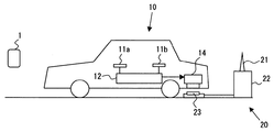
以下、本発明の実施形態に係る充電システムを、図に基づいて説明する。図1は、本実施形態による充電システムの全体の構成を示す構成図である。図1に示すように、本実施形態における充電システムは、主に携帯機(電子キー)1と、車両側ユニット10と、充電装置20とから構成される。
Hereinafter, a charging system according to an embodiment of the present invention will be described with reference to the drawings. FIG. 1 is a configuration diagram showing the overall configuration of the charging system according to the present embodiment. As shown in FIG. 1, the charging system in the present embodiment mainly includes a portable device (electronic key) 1, a
携帯機1は車両の運転者等のユーザに保持されるものであり、車両側ユニット10及び充電装置20との通信機能を備えている。本実施形態では、この携帯機1の通信機能を利用して、ユーザが車両や充電装置から遠ざかっているのか、接近しているのかを判定する。
The portable device 1 is held by a user such as a vehicle driver and has a communication function with the vehicle-
車両側ユニット10は、携帯機1と通信するためのアンテナ11a、11b及び制御部12を備え、携帯機1との通信結果に基づいて、車両の蓄電装置14の充電の開始や終了などの充電状態を制御するとともに、車両の各ドアのロック・アンロック状態を制御する。
The vehicle-
充電装置20は、主に、アンテナ21、制御部22、及び給電部23とからなり、車両が駐車される駐車位置近傍に設置されている。この充電装置20は、車両が充電装置20に対して所定位置に停車されたときに車両の蓄電装置14に電力を供給して、当該蓄電装置14を充電するものである。
The charging
以下、携帯機1、車両側ユニット10、及び充電装置20に関して、図2のブロック図を参照しつつ、より詳細に説明する。なお、図2では、図示の便宜上、ドアのロック・アンロック状態を制御する制御ユニットを、車両の右側のみに示しているが、この制御ユニットは、車両の各ドアに設けられる。ただし、ドアのロック・アンロック状態を制御する制御ユニットは前席用のドアや運転席用のドアのみに設けても良い。
Hereinafter, the portable device 1, the vehicle-
図2に示すように、携帯機1は、車両側ユニット10の車室外送信機2a、2bあるいは車室内送信機8からのリクエスト信号を受信する受信機1a、このリクエスト信号の受信に応答して、固有のIDコード等を含むレスポンス信号を送信する送信機1bを備えている。携帯機ECU1cは、上述した受信機1a及び送信機1bと接続され、各種の制御処理を実行する。具体的には、携帯機ECU1cは、受信機1aの受信信号に基づいてリクエスト信号の受信の有無を判定したり、そのリクエスト信号に応答して、IDコード等を含むレスポンス信号を生成して、送信機1bから送信させたりする。
As shown in FIG. 2, the portable device 1 includes a
また、図示していないが、携帯機1には、車両のドアをロックするためのロック操作ボタン、及び車両のドアをアンロックするためのアンロック操作ボタンが設けられている。ユーザによってこれらの操作ボタンのいずれかが操作されると、携帯機ECU1cは、上記したIDコードとともに、ロック指示信号又はアンロック指示信号を送信機1bから送信させる。
Although not shown, the portable device 1 is provided with a lock operation button for locking the vehicle door and an unlock operation button for unlocking the vehicle door. When one of these operation buttons is operated by the user, the portable device ECU 1c causes the
車両側ユニット10は、車両の各ドア15、16に設けられた車室外送信機2a、2b及び車室内に設けられた車室内送信機8を有する。これらの車室外送信機2a、2b及び車室内送信機8は、車両側ユニット10の照合ECU4からの送信指示信号に基づいてリクエスト信号を発信する。
The vehicle-
車室外送信機2a、2bのリクエスト信号の到達距離は、例えば数メートル程度に設定される。車両が、各ドア15、16がロックされた状態で駐車されている時には、そのリクエスト信号の到達距離に応じた通信エリアが車両の各ドア15、16の周囲に形成され、携帯機1を保持するユーザが車両から遠ざかったことや、車両に接近したことを検知できるようにしている。また、車室内送信機8による通信エリアは、車室内をカバーするように設定され、携帯機1が車室内にあるか否かを検知する。
The arrival distance of the request signal of the vehicle
また、車両側ユニット10は、車両の車室内に設けられ、送信機2a、2b、8に対する送信指示信号の出力と同期してレスポンス信号受信可能状態にされて、携帯機1から送信されるレスポンス信号を受信する受信機3を有する。受信機3が受信したレスポンス信号は、照合ECU4に出力される。照合ECU4は、この受信したレスポンス信号に含まれるIDコードが予め登録されている登録コードと一致等、所定の関係を満足するかの照合を行う。
The vehicle-
そして、照合ECU4は、所定の関係を満足するとの照合結果が得られた場合、ドア15,16のロック・アンロック状態等を制御すべく、制御信号をボデーECU7に出力する。例えば、ドア15,16がロックされた状態で上述の照合結果が得られた場合、照合ECU4は、ドアのアンロック許可信号をボデーECU7に出力する。このとき、ボデーECU7は、ドアハンドル11a,11bに設けられたタッチスイッチ6a1,6b1(後述する)に通電して、ユーザによるドアハンドル11a,11bの操作を検知可能にする。そして、タッチスイッチ6a1,6b1により、ユーザの操作が検知されると、ロック制御部5a,5bにアンロック指示を出力して、各ドア15,16をアンロックする。逆に、ドア15,16がロックされていない状態で上述の照合結果が得られ、かつユーザによりドアロックスイッチ6a2,6b2(後述する)が操作されたことが検知されると、ロック制御部5a,5bにロック指示を出力して各ドア15,16をロックする。
And when the collation result that the predetermined relationship is satisfied is obtained, the collation ECU 4 outputs a control signal to the body ECU 7 in order to control the locked / unlocked state of the
また、照合ECU4は、携帯機1から上述したロック指示信号又はアンロック指示信号を受信したときにも、その指示信号に応じた制御信号をボデーECU7に出力する。 In addition, when the verification ECU 4 receives the above-described lock instruction signal or unlock instruction signal from the portable device 1, the verification ECU 4 outputs a control signal corresponding to the instruction signal to the body ECU 7.
さらに、照合ECU4は、車室外送信機2a,2bを用いて携帯機1との通信が行なわれている状態から、その通信が途絶える状態に変化したとき、携帯機1を保持したユーザが車両から遠ざかっていると判定する。一方、携帯機1との通信が行なわれていない状態から、その通信が開始された状態に変化したとき、携帯機1を保持したユーザが車両に接近していると判定する。照合ECU4は、これらの判定結果に基づいて、充電ECU13に対して充電準備、充電開始、充電準備の解除、あるいは充電終了を指示する。照合ECU4が、充電ECU13に対して充電準備、充電開始、充電準備の解除、あるいは充電終了を指示する際には、少なくとも1つの車室外送信機2a、2bを用いて、充電開始指示あるいは充電終了指示として、充電装置20に対しても同様の指示を送信する。
Furthermore, when the communication ECU 4 changes from a state in which communication with the portable device 1 is performed using the
ボデーECU7は、各車両ドア15,16のロック・アンロック状態を制御するための駆動信号を各ドア15,16に設けられたロック制御部5a、5bに出力するものである。ロック制御部5a、5bは、ボデーECU7からロック信号またはアンロック信号が送信されたとき、そのロック信号またはアンロック信号に応じて正転/逆転するドアロックモータを有し、このドアロックモータの回転によって各車両ドア15、16をロック、またはアンロックする。
The body ECU 7 outputs a drive signal for controlling the locked / unlocked state of the
車両の各ドア15、16に設けられたドアハンドル11a、11bは、車室外送信機2a、2bのアンテナとしての役割を備えている。このドアハンドル11a,11bには、タッチスイッチ6a1,6b1が設けられており、携帯機1の保持者が、ドアハンドル11a、11bに触れて、ドアハンドル11a、11bに対して操作を行ったことを検出することが可能である。このドアハンドル11a、11bに対する操作が検出された場合、各ドア15、16がアンロックされる。また、ドアハンドル11a、11bには、プッシュスイッチとして構成されたドアロックスイッチ6a2,6b2も設けられている。ユーザが、このドアロックスイッチ6a2,6b2を操作すると、各ドア15,16をロックすることができる。
Door handles 11a and 11b provided on the
充電ECU13は、照合ECU4からの指示に従って、バッテリ14aと受電部14bとからなる蓄電装置14の充電状態を制御するものである。具体的には、照合ECU4から充電準備指示が与えられると、充電ECU13は、例えば受電部14bを収納しているリッドを開いたり、受電部14bを充電装置20の給電部23に向けて下降させたりして、受電部14bにて、充電装置20の給電部23から供給される電力を受電可能な状態にする。なお、受電部14bと給電部23は、非接触状態を保ちながら電磁的な結合によって電力の授受が行われるものであるが、受電部14bと給電部23の端子同士を接触させて、電力の授受が行われても良い。
The charging
また、照合ECU4から充電準備指示に続いて充電開始指示が与えられると、充電ECU13は、受電部14bにて受電した電力をバッテリ14aに供給する回路をオンして、充電装置20から供給される電力によるバッテリ14aの充電を開始する。
Further, when a charging start instruction is given from the verification ECU 4 following the charging preparation instruction, the charging
一方、照合ECU4から充電準備指示が与えられた後に、充電準備の解除指示が与えられると、充電ECU13は、上述したリッドを閉じたり、受電部14bを元の位置まで上昇させたりして、充電準備状態を解消する。これにより、ユーザは即座に車両を使用できる状態となる。
On the other hand, when a charge preparation release instruction is given after the charge preparation instruction is given from the verification ECU 4, the
照合ECU4から充電終了指示が与えられた場合には、受電部14bにて受電した電力をバッテリ14aに供給する回路をオフするとともに、上述した充電準備解除指示を受けたときと同様の制御を行い、充電準備状態を解消する。
When a charge end instruction is given from the verification ECU 4, the circuit that supplies the power received by the
充電装置20の制御部22は、充電装置ECU22aと通信機22bとを有し、アンテナ21を介して、携帯機1及び車両側ユニット10と通信を行なうことが可能である。この充電装置20の制御部22も、上述した車両側ユニット10と同様に、携帯機1に対して定期的にリクエスト信号を送信し、そのリクエスト信号に応答するレスポンス信号の有無の変化により、携帯機1を保持したユーザが充電装置20から遠ざかっているのか、または接近しているのかを判定する。なお、充電装置20の制御部22にも、当該充電装置20を利用する車両の携帯機1のIDコードが事前に登録されており、IDコードが一致するとの照合がなされた場合のみ、その通信状態の変化からユーザの接近・離間を判定する。このように制御部22に事前にIDコードを登録しておくことにより、予め登録された車両に対してのみ充電を行ったり、充電量に応じた課金処理を行なうことも可能となる。また、充電装置20に画像認識装置や近接センサ等を設け、車両が停車しているときにのみリクエスト信号を送信するようにすることが好ましい。
The
充電装置ECU22aは、ユーザが遠ざかっていると判定した場合、例えば給電部23を上昇等させることにより、給電部23を受電部14bに対して所定位置まで移動させて充電準備動作を行う。この充電準備動作は、車両側ユニット10から、充電準備指示が得られたときにも実行される。すなわち、携帯機1との通信結果、もしくは車両側ユニット10からの指示の内、いずれか早く得られた方に基づいて、充電準備動作を行うのである。
When the
充電準備動作後、所定時間経過するか、もしくは車両側ユニット10から充電開始指示が得られると、充電装置20における充電動作を開始する。具体的には、給電部23から受電部14bへと電力が供給されるように、給電部23に対して通電を開始する。
When a predetermined time elapses after the charging preparation operation or a charging start instruction is obtained from the vehicle-
充電準備動作を行った後に、携帯機1との通信が再開されたとき、もしくは車両側ユニット10から充電準備解除指示が得られた場合には、充電装置ECU22aは、上述した充電準備動作を終了させ、給電部23を初期位置に戻す。また、車両側ユニット10から充電終了指示が得られた場合には、充電装置ECU22aは、給電部23に対する通電を終了するとともに、給電部23を初期位置に復帰させる。
When the communication with the portable device 1 is resumed after the charge preparation operation is performed, or when the charge preparation release instruction is obtained from the vehicle-
なお、充電装置20の制御部22は、自らリクエスト信号を送信して携帯機1との通信を行なわず、車両側ユニット10と携帯機1間の通信をモニタすることにより、携帯機1からのレスポンス信号を取得しても良い。また、充電装置20における充電動作は、携帯機1との通信結果によらず、車両側ユニット10からの指示のみに基づいて行われるものであっても良い。この場合、車両側ユニット10からの指示として、IDコードを含む指示を得るようにすれば、予め登録された車両に対してのみ充電を行なったり、充電量に応じた課金処理を行なうことも可能である。
Note that the
次に、上述した車両側ユニット10と携帯機1との相互通信によるIDコードの照合結果を基に、照合ECU4が実行する充電制御に関して、図3及び図4のフローチャートに基づいて詳細に説明する。なお、図3のフローチャートに示す処理は、充電を開始するための制御処理であって、所定時間ごとに起動されて実施されるものである。また、図4のフローチャートに示す処理は、充電を終了させるための制御処理であって、図3のフローチャートの処理により充電が開始された後に実行されるものである。
Next, charging control executed by the verification ECU 4 will be described in detail based on the flowcharts of FIGS. 3 and 4 on the basis of the ID code verification result by mutual communication between the vehicle-
まず、図3のフローチャートに示す充電開始処理について説明する。ステップS100では、車両のエンジンが停止され、かつ各ドア15、16がロックされた状態で駐車されているか否かを判定する。この判定が肯定された場合、ステップS110の処理に進む。一方、この判定が否定された場合には、ユーザが車両の使用を終了したとみなすことができないため、図3のフローチャートに示す処理を終了する。なお、車両のエンジンが停止され、かつ各ドア15、16がロックされた状態で駐車されているとき、照合ECU4は、所定時間経過毎に車室外送信機2a、2bに対してリクエスト信号の送信を指示する。
First, the charging start process shown in the flowchart of FIG. 3 will be described. In step S100, it is determined whether or not the vehicle is parked with the engine of the vehicle stopped and the
ステップS110では、車両が充電装置20から電力の供給を受けてバッテリ14aを充電することが可能な位置に停車したか否かを判定する。この判定は、例えば車両に画像認識装置や充電装置20に対する位置を検出するための複数の距離センサ等を設けて、それらの検出結果に基づいて行うことができる。また、充電装置20に、それらの画像認識装置や複数の距離センサを設け、その検知結果を通信による取得することによって判定しても良い。
In step S110, it is determined whether or not the vehicle has stopped at a position where the
ステップS120では、充電に適した状況であり、充電を行うことが許可されるか否かを判定する。例えば、蓄電装置14に異常があって充電が正常に行い得ない状態であったり、既に満充電状態であり充電が不要な状態であったりする場合には、充電に不適切な状況である。従って、このような場合には、充電は許可されないと判定される。さらには、例えば車両に、周囲に存在する人体を検知可能な赤外線センサなどを設けた場合であって、車両の周囲に人が存在することを検知した場合に、充電に不適切な状況であるとみなし、充電を許可しないようにしても良い。それ以外の場合には、充電を行うのに適した状況であるとみなし、充電が許可されたと判定する。充電が許可されたと判定すると、ステップS130の処理に進む。一方、充電が許可されないと判定すると、図3のフローチャートに示す処理を終了する。
In step S120, it is determined whether or not charging is permitted because the situation is suitable for charging. For example, when there is an abnormality in the
ステップS130では、車室外送信機2a,2bを用いて、IDコードが一致するとの照合結果が得られる携帯機1との通信がなされていた状態から、その通信が行なわれなくなった状態に変化したか否かを判定する。この判定が肯定されたとき、携帯機1を保持するユーザは、車両のエンジンを停止し、ドア15,16にロックをかけた状態で、車室外送信機2a,2bの送信エリア内から送信エリア外に移動したことを意味するので、ユーザは車両から遠ざかっているとみなすことができる。このような場合、ユーザが車両の使用を終了し、その後しばらくの間は車両を使用しない可能性が高い。従って、ステップS130の判定が肯定された場合には、ステップS160に進んで、充電ECU13に対して充電準備を指示するとともに、充電装置20に対しても充電指示を送信する。これにより、車両においても、充電装置20においても、バッテリ14aの充電のための準備動作を開始することができる。
In step S130, the state in which the communication with the portable device 1 that can obtain a collation result indicating that the ID codes match using the
ステップS170では、タイマをスタートさせ、ステップS180では、そのタイマによる計時時間が所定時間に達したか否かを判定する。この際、所定時間に達していないとの否定判定がなされると、ステップS130の処理に戻る。なお、ステップS170において一旦タイマがスタートされると、ステップS170の処理が再度行われた場合に、再びタイマがスタートされることはなく、タイマは計時を継続する。このステップS170,180の処理は、携帯機1を保持するユーザが確実に車両から遠ざかっていることを確認するために設けられている。 In step S170, a timer is started. In step S180, it is determined whether or not the time counted by the timer has reached a predetermined time. At this time, if a negative determination is made that the predetermined time has not been reached, the process returns to step S130. Note that once the timer is started in step S170, when the process of step S170 is performed again, the timer is not started again, and the timer continues counting. The processes in steps S170 and 180 are provided to confirm that the user holding the portable device 1 is surely moving away from the vehicle.
ステップS180の判定が肯定されると、ステップS190に進んで、充電ECU13に対して充電開始を指示するとともに、充電装置20に対して充電開始指示を送信する。これにより、充電装置20から供給される電力により、バッテリ14aの充電が開始される。
When the determination in step S180 is affirmed, the process proceeds to step S190, where the charging
ステップS130の判定が否定された場合、すなわち、携帯機1との通信が行なわれている状態から通信が途絶えた状態へと変化していないと判定された場合、ステップS140の処理に進む。ステップS140では、携帯機1との通信が途絶えている状態から、その通信が行なわれる状態に変化したか否かを判定する。この判定が肯定された場合には、ステップS200に進んで充電準備解除指示を充電ECU13に与えるとともに、充電装置20にも充電準備解除指示を送信する。
If the determination in step S130 is negative, that is, if it is determined that the communication has not been changed from the state in which communication with the portable device 1 is being performed, the process proceeds to step S140. In step S140, it is determined whether or not the state in which communication with the portable device 1 is interrupted has changed to a state in which communication is performed. When this determination is affirmed, the process proceeds to step S200, and a charging preparation release instruction is given to the charging
ステップS140の判定が肯定されるのは、携帯機1を保持したユーザが一旦車両から離れたが、タイマによる計時時間が所定時間に達する前に、車両の近傍に戻ってきた場合である。このような場合、例えば一旦車両を離れたが、直ぐに用事を思い出して車両まで戻ってきたなど、再度車両を使用する可能性も考えられる。そのため、ステップS200において充電準備を解除して、ユーザが即座に車両を使用できるように備えるのである。 The determination in step S140 is affirmative when the user holding the portable device 1 has once left the vehicle, but has returned to the vicinity of the vehicle before the time measured by the timer reaches a predetermined time. In such a case, there is a possibility that the vehicle will be used again, for example, once it has left the vehicle, but immediately remembered the errand and returned to the vehicle. For this reason, the preparation for charging is canceled in step S200 so that the user can immediately use the vehicle.
なお、上述したように、携帯機1には、車両のドアをアンロックするためのアンロック操作ボタンが設けられており、そのアンロック操作ボタンの操作により携帯機1から送信されるアンロック指示信号の到達距離は、車両側ユニット10の車室外送信機2a,2bの通信エリアよりも長い。そのため、ステップS140の判定が否定されたときには、ステップS150において、携帯機1からアンロック指示信号が送信されて、ドア15,16をアンロックすることが要求されているか否かを判定する。ユーザによりアンロック要求が出されている場合、ユーザは車両を再び使用する可能性が高い。このため、ステップS150の判定が肯定されたときには、ステップS140の判定が肯定されたときと同様に、ステップS200の処理に進んで、充電準備の解除処理を実行する。
As described above, the portable device 1 is provided with the unlock operation button for unlocking the door of the vehicle, and the unlock instruction transmitted from the portable device 1 by the operation of the unlock operation button. The reach distance of the signal is longer than the communication area of the vehicle interior side outside
なお、ステップS140及びS150にて、いずれも否定判定された場合には、ステップS160に進み、充電準備状態を維持しつつタイマによる所定時間の計時を継続する。 In addition, when negative determination is made in both steps S140 and S150, the process proceeds to step S160, and the time measurement for a predetermined time by the timer is continued while maintaining the charge preparation state.
このような処理によって、ユーザが車両の使用を終了し、その後しばらくの間は車両を使用しない可能性が高いタイミングでバッテリの充電を開始させることができる。 By such processing, the user can finish using the vehicle, and can start charging the battery at a timing when there is a high possibility that the user will not use the vehicle for a while thereafter.
次に、図4のフローチャートに基づいて、充電終了時の処理について説明する。まずステップS300では、バッテリ14aに十分な電力が充電され、バッテリ14aが満充電状態となったか否かを判定する。このステップS300の判定が肯定されると、ステップS330の処理に進んで、充電ECU13に対して充電終了指示を与えるとともに、充電装置20に対して充電終了指示を送信する。
Next, processing at the end of charging will be described based on the flowchart of FIG. First, in step S300, it is determined whether or not sufficient power is charged in the
ステップS300の判定が否定されると、ステップS310に進み、携帯機1との通信が途絶えている状態から、その通信が行なわれる状態に変化したか否かを判定する。この判定が肯定された場合には、ステップS300に進んで、上述した充電終了処理を実行する。ステップS310の判定が否定された場合には、ステップS320の処理に進んで、携帯機1からアンロック指示信号が送信されて、ドア15,16をアンロックすることが要求されているか否かを判定する。この判定が肯定された場合には、ステップS300に進んで、上述した充電終了処理を実行する。
If the determination in step S300 is negative, the process proceeds to step S310, and it is determined whether or not the state where communication with the portable device 1 has been interrupted has changed to a state where communication is performed. When this determination is affirmed, the process proceeds to step S300, and the above-described charging end process is executed. If the determination in step S310 is negative, the process proceeds to step S320, and whether or not an unlock instruction signal is transmitted from the portable device 1 to request unlocking of the
バッテリ14aの充電が開始された後に、ステップS310により携帯機1を保持したユーザが車両に接近していることが判明した場合や、ステップS320によりユーザによって車両ドアのアンロック要求がなされたことが判明した場合、ユーザはその後車両に乗り込んで、車両を使用する可能性が高い。そのため、ユーザが車両に接近していることが判明した時点、またはユーザによりアンロック要求がなされた時点で充電終了処理を実行する。これにより、ユーザが車両に乗り込んだときには、即座に車両が走行を開始することが可能な状態となる。
After charging of the
以上、本発明の好ましい実施形態について説明したが、本発明は、上述した実施形態になんら制限されることなく、本発明の主旨を逸脱しない範囲において、種々変形して実施することが可能である。 The preferred embodiments of the present invention have been described above. However, the present invention is not limited to the above-described embodiments, and various modifications can be made without departing from the spirit of the present invention. .
例えば、上述した実施形態では、車両側ユニットが照合ECU4、ボデーECU7、及び充電ECU13を有する例について説明した。しかしながら、必要な機能を発揮しえる限り、これらのECUは統合されても良いし、さらに多数のECUによって構成するようにしても良い。
For example, in the above-described embodiment, the example in which the vehicle-side unit includes the verification ECU 4, the body ECU 7, and the charging
また、ドアのアンロックを指示する操作とロックを指示する操作とは、上述した各実施形態のように、別々の操作部(ドアハンドルとロックスイッチ)に対して行われても良いし、共通の操作部に対して行われても良い。 Further, the operation for instructing the unlocking of the door and the operation for instructing the locking may be performed on different operation units (door handle and lock switch) as in the above-described embodiments, or may be common. The operation unit may be performed.
さらに、例えば、自宅の駐車場に充電装置20を設置し、かつ自宅の玄関ドアに対して、上述した携帯機1のボタン操作によってロック指示を行うと玄関ドアのロックが可能である場合には、当該玄関ドアに対するロック指示を車両側ユニット10で受信し、そのロック指示に基づいて、充電終了処理を行なっても良い。
Furthermore, for example, when the charging
なお、上述した実施形態では、携帯機1と車両側ユニット10とが、いわゆるスマートエントリーシステムとしての機能とキーレスエントリーシステムとしての機能とを同時に備えるものであったが、いずれか一方の機能のみを備えるものであっても良い。いずれの場合でも、本実施形態の充電システムにおける、携帯機や車両側ユニットなどは、スマートエントリーシステムやキーレスエントリーシステムとして既に実用化されているものと共用することもできる。
In the above-described embodiment, the portable device 1 and the vehicle-
1…携帯機、1a…受信機、1b…送信機、1c…携帯機ECU、2a、2b…車室外送信機、3…受信機、4…照合ECU、5a、5b…ロック制御部、6a1、6b1…タッチセンサ、6a2、6b2…ロックスイッチ、7…ボデーECU、8…車室内送信機、10…車両側ユニット、11a、11b…ドアハンドル(アンテナ)、12…制御部、13…充電ECU、14…蓄電装置、14a…バッテリ、14b…受電部、20…充電装置、21…アンテナ、22…制御部、22a…充電装置ECU、22b…通信機、23…給電部
DESCRIPTION OF SYMBOLS 1 ... Portable machine, 1a ... Receiver, 1b ... Transmitter, 1c ... Portable machine ECU, 2a, 2b ... Outside transmitter, 3 ... Receiver, 4 ... Verification ECU, 5a, 5b ... Lock control part, 6a1, 6b1 ... Touch sensor, 6a2, 6b2 ... Lock switch, 7 ... Body ECU, 8 ... Vehicle interior transmitter, 10 ... Vehicle side unit, 11a, 11b ... Door handle (antenna), 12 ... Control unit, 13 ... Charge ECU, DESCRIPTION OF
Claims (10)
前記車両の運転者によって保持され、通信機能を備えた携帯機と、
前記携帯機と通信を行なう、前記車両に搭載された車両側通信機と、
前記車両に搭載されて、前記車両側通信機による前記携帯機との通信結果に基づいて、運転者が車両から遠ざかっていると判定されたとき、前記バッテリの充電を開始させ、運転者が車両に接近していると判定されたとき、前記バッテリの充電を終了させるバッテリ充電制御部と、を備えることを特徴とする充電システム。 When the vehicle is stopped at a predetermined position, a charging device that is installed in the vicinity of the stop position and charges a battery mounted on the vehicle;
A portable device held by a driver of the vehicle and provided with a communication function;
A vehicle-side communication device mounted on the vehicle for communicating with the portable device;
When it is determined that the driver is moving away from the vehicle based on the result of communication with the portable device by the vehicle-side communication device, charging of the battery is started and the driver starts the vehicle And a battery charge control unit that terminates charging of the battery when it is determined that the battery is approaching the battery.
前記バッテリ充電制御部は、前記バッテリの充電を開始させる際に、前記充電装置に対して充電開始を指示し、前記バッテリの充電を終了させる際に、前記充電装置に対して充電終了を指示するものであって、当該制御部からの指示は、前記車両側通信機と前記充電装置側通信機との通信により前記充電装置に与えられ、
前記充電装置は、前記携帯機との通信結果と、前記バッテリ充電制御部からの指示のいずれか早く得られた方に基づいて、当該充電装置における充電動作の開始及び終了を実行することを特徴とする請求項1に記載の充電システム。 The charging device includes a charging device side communication device, and the charging device side communication device performs communication with the portable device and determines that the driver is moving away from the charging device based on the communication result. When the charging operation in the charging device is started and it is determined that the driver is approaching the charging device, the charging operation in the charging device is terminated.
The battery charge control unit instructs the charging device to start charging when starting charging of the battery, and instructs the charging device to end charging when finishing charging of the battery. The instruction from the control unit is given to the charging device through communication between the vehicle-side communication device and the charging device-side communication device,
The charging device executes start and end of a charging operation in the charging device based on a communication result with the portable device or an instruction from the battery charge control unit which is obtained earlier. The charging system according to claim 1.
前記車両側通信機が受信したIDコードが、予め登録されているIDコードに一致した場合に、前記バッテリ充電制御部は、前記携帯機との通信結果に基づいて前記バッテリの充電を開始又は終了させることを特徴とする請求項1に記載の充電システム。 When the portable device communicates with the vehicle-side communication device, the portable device transmits a unique ID code to the vehicle-side communication device,
When the ID code received by the vehicle-side communication device matches a pre-registered ID code, the battery charge control unit starts or ends charging of the battery based on the communication result with the portable device The charging system according to claim 1, wherein:
前記充電装置側通信機が受信したIDコードが、予め登録されているIDコードに一致した場合に、前記充電装置は、前記携帯機との通信結果に基づいて当該充電装置における充電動作を開始又は終了することを特徴とする請求項2に記載の充電システム。 When the portable device communicates with the charging device side communication device, the portable device transmits an ID code unique to the charging device side communication device,
When the ID code received by the charging device-side communication device matches a pre-registered ID code, the charging device starts charging operation in the charging device based on the communication result with the portable device or The charging system according to claim 2, wherein the charging system is terminated.
前記携帯機は、前記通信エリアに進入して前記リクエスト信号を受信すると、そのリクエスト信号に応答するレスポンス信号を返送するものであって、
前記バッテリ充電制御部は、前記車両側通信機が前記レスポンス信号を受信している状態から前記レスポンス信号の受信ができない状態に変化したとき、運転者が車両から遠ざかっていると判定し、前記車両側通信機が前記レスポンス信号を受信していない状態から前記レスポンス信号を受信する状態に変化したとき、運転者が車両に接近していると判定することを特徴とする請求項1に記載の充電システム。 The vehicle-side communication device has a communication area of a predetermined range around the vehicle, and repeatedly transmits a request signal in the communication area,
When the portable device enters the communication area and receives the request signal, it returns a response signal in response to the request signal,
The battery charge control unit determines that the driver is moving away from the vehicle when the vehicle-side communication device changes from a state in which the vehicle-side communication device receives the response signal to a state in which the response signal cannot be received, and the vehicle 2. The charging according to claim 1, wherein when a side communication device changes from a state in which the response signal is not received to a state in which the response signal is received, it is determined that the driver is approaching the vehicle. system.
前記車両のドアに設けられ、アンロック指示のために操作されるアンロック操作部と、
前記ロック操作部及び前記アンロック操作部に対する運転者の操作に応じて、前記車両のドアをロックまたはアンロックするロック・アンロック制御部とを備え、
前記バッテリ充電制御部は、前記車両側通信機が受信したレスポンス信号に含まれるIDコードが登録IDコードと一致したときに、前記ロック・アンロック制御部に対して前記車両のドアをロックまたはアンロックすることを許可する許可信号を出力することを特徴とする請求項7又は8に記載の充電システム。 A lock operating unit provided on the door of the vehicle and operated for a lock instruction;
An unlock operation unit provided on the door of the vehicle and operated for an unlock instruction;
A lock / unlock control unit that locks or unlocks the door of the vehicle according to a driver's operation on the lock operation unit and the unlock operation unit,
The battery charge control unit locks or unlocks the vehicle door with respect to the lock / unlock control unit when an ID code included in a response signal received by the vehicle-side communication device matches a registered ID code. 9. The charging system according to claim 7, wherein a permission signal for permitting locking is output.
前記車両は、前記車両側通信機が前記ロック信号または前記アンロック信号を受信したことに応じて、前記車両のドアをロックまたはアンロックするロック・アンロック制御部を有し、
前記バッテリ充電制御部は、前記車両側通信機が前記ロック信号を受信したとき、運転者が車両から遠ざかっていると判定し、前記車両側通信機が前記アンロック信号を受信したとき、運転者が車両に接近していると判定することを特徴とする請求項1に記載の充電システム。 The communication device includes a lock operation unit operated for a lock instruction and an unlock operation unit operated for an unlock instruction, and transmits a lock signal when the lock operation unit is operated. , An unlock signal is transmitted when the unlock operation unit is operated,
The vehicle has a lock / unlock control unit that locks or unlocks a door of the vehicle in response to the vehicle-side communication device receiving the lock signal or the unlock signal,
The battery charge control unit determines that the driver is moving away from the vehicle when the vehicle-side communication device receives the lock signal, and the driver when the vehicle-side communication device receives the unlock signal. The charging system according to claim 1, wherein it is determined that the vehicle is approaching the vehicle.
Priority Applications (2)
| Application Number | Priority Date | Filing Date | Title |
|---|---|---|---|
| JP2007251815A JP2009089452A (en) | 2007-09-27 | 2007-09-27 | Charging system |
| US12/235,950 US7795841B2 (en) | 2007-09-27 | 2008-09-23 | Charging system including user proximity detection to start or stop charging |
Applications Claiming Priority (1)
| Application Number | Priority Date | Filing Date | Title |
|---|---|---|---|
| JP2007251815A JP2009089452A (en) | 2007-09-27 | 2007-09-27 | Charging system |
Publications (1)
| Publication Number | Publication Date |
|---|---|
| JP2009089452A true JP2009089452A (en) | 2009-04-23 |
Family
ID=40507430
Family Applications (1)
| Application Number | Title | Priority Date | Filing Date |
|---|---|---|---|
| JP2007251815A Withdrawn JP2009089452A (en) | 2007-09-27 | 2007-09-27 | Charging system |
Country Status (2)
| Country | Link |
|---|---|
| US (1) | US7795841B2 (en) |
| JP (1) | JP2009089452A (en) |
Cited By (17)
| Publication number | Priority date | Publication date | Assignee | Title |
|---|---|---|---|---|
| JP2010093957A (en) * | 2008-10-08 | 2010-04-22 | Honda Motor Co Ltd | Charging system for vehicle |
| JP2010259248A (en) * | 2009-04-27 | 2010-11-11 | Mitsubishi Electric Corp | Vehicle charging system |
| JP2011045231A (en) * | 2009-07-24 | 2011-03-03 | Denso Corp | Vehicle door control system, on-vehicle door controller, portable terminal, program for on-vehicle door controller, program for portable terminal, charged state notification system, charged state monitoring apparatus, and program for charged state monitoring apparatus |
| JP2011114998A (en) * | 2009-11-30 | 2011-06-09 | Tokai Rika Co Ltd | Charging system |
| JP2011120386A (en) * | 2009-12-03 | 2011-06-16 | Mitsubishi Motors Corp | Apparatus for control of charging electric vehicle |
| JP2011166971A (en) * | 2010-02-10 | 2011-08-25 | Enegate:Kk | Power supplying system for electric vehicle |
| WO2012090612A1 (en) | 2010-12-27 | 2012-07-05 | 日産自動車株式会社 | Non-contact charging device |
| WO2012176264A1 (en) * | 2011-06-20 | 2012-12-27 | トヨタ自動車株式会社 | Non-contact power reception device, non-contact power transmission device, and non-contact power reception and transmission system |
| WO2012176265A1 (en) * | 2011-06-20 | 2012-12-27 | トヨタ自動車株式会社 | Non-contact receiving device, non-contact transmitting device, and non-contact transmitting/receiving system |
| JP2013090462A (en) * | 2011-10-19 | 2013-05-13 | Mitsubishi Motors Corp | Power feed control device for power supply device |
| JP2013219865A (en) * | 2012-04-05 | 2013-10-24 | Mitsubishi Electric Corp | Electrically driven vehicle and charge control method of the same |
| JP2013251944A (en) * | 2012-05-30 | 2013-12-12 | Mitsubishi Nichiyu Forklift Co Ltd | Charging system |
| JP2014011849A (en) * | 2012-06-28 | 2014-01-20 | Toshiba Corp | Charge/discharge control device |
| JP2015043691A (en) * | 2014-11-04 | 2015-03-05 | 三菱自動車工業株式会社 | Portable type power supply device |
| JP2015226329A (en) * | 2014-05-26 | 2015-12-14 | 三菱電機株式会社 | Charging/discharging system for electric automobile and authentication method for charging/discharging system for electric automobile |
| KR101826494B1 (en) | 2015-04-07 | 2018-02-06 | 닛산 지도우샤 가부시키가이샤 | Locking / Unlocking System |
| US11878596B2 (en) | 2020-03-18 | 2024-01-23 | Honda Motor Co., Ltd. | Non-contact charging system and vehicle |
Families Citing this family (55)
| Publication number | Priority date | Publication date | Assignee | Title |
|---|---|---|---|---|
| US8855554B2 (en) | 2008-03-05 | 2014-10-07 | Qualcomm Incorporated | Packaging and details of a wireless power device |
| KR101589836B1 (en) | 2008-04-21 | 2016-01-28 | 퀄컴 인코포레이티드 | Short range efficient wireless power transfer |
| US8497658B2 (en) | 2009-01-22 | 2013-07-30 | Qualcomm Incorporated | Adaptive power control for wireless charging of devices |
| CN102448765B (en) * | 2009-05-28 | 2014-09-10 | 丰田自动车株式会社 | Charging system, and method for controlling vehicle and charging system |
| DE112011100550B4 (en) * | 2010-02-16 | 2022-02-03 | Mitsubishi Electric Corporation | cell capacity adjuster |
| DE102010009727A1 (en) * | 2010-03-01 | 2011-09-01 | Audi Ag | Method for charging a battery of a motor vehicle with electric drive and motor vehicle with electric drive |
| DE102010009715A1 (en) * | 2010-03-01 | 2011-09-01 | Audi Ag | Method for charging a battery of a motor vehicle, and motor vehicle |
| US20110302078A1 (en) | 2010-06-02 | 2011-12-08 | Bryan Marc Failing | Managing an energy transfer between a vehicle and an energy transfer system |
| JP5010715B2 (en) * | 2010-06-17 | 2012-08-29 | トヨタ自動車株式会社 | Vehicle parking assist device and electric vehicle including the same |
| JP5170177B2 (en) * | 2010-06-30 | 2013-03-27 | トヨタ自動車株式会社 | Vehicle anti-theft device |
| JP2012034484A (en) * | 2010-07-30 | 2012-02-16 | Toyota Industries Corp | Power supply device and vehicle |
| JP2012080646A (en) * | 2010-09-30 | 2012-04-19 | Tokai Rika Co Ltd | Power feeding plug locking device |
| US8172599B2 (en) * | 2010-10-11 | 2012-05-08 | GM Global Technology Operations LLC | Electric vehicle charge cord lock |
| US20120280653A1 (en) * | 2011-05-03 | 2012-11-08 | Green Charge Networks | Electric Vehicle Fleet Management Charging Station Systems and Methods |
| US8265816B1 (en) * | 2011-05-27 | 2012-09-11 | General Electric Company | Apparatus and methods to disable an electric vehicle |
| US9379571B2 (en) * | 2011-07-11 | 2016-06-28 | Delphi Technologies, Inc. | Electrical charging system having energy coupling arrangement for wireless energy transmission therebetween |
| DE102011114549A1 (en) * | 2011-09-30 | 2013-04-04 | Audi Ag | Method for operating a vehicle that can be driven by an electric motor |
| WO2013065168A1 (en) * | 2011-11-04 | 2013-05-10 | トヨタ自動車株式会社 | Vehicle and vehicle control method |
| US9318903B2 (en) * | 2012-01-31 | 2016-04-19 | General Electric Company | Methods and systems for controlling a charging device |
| JP2013198322A (en) * | 2012-03-21 | 2013-09-30 | Tokai Rika Co Ltd | On-vehicle non-contact charging system |
| US10773596B2 (en) | 2012-07-19 | 2020-09-15 | Ford Global Technologies, Llc | Vehicle battery charging system and method |
| US20140021913A1 (en) * | 2012-07-19 | 2014-01-23 | Ford Global Technologies, Llc | Vehicle battery charging system and method |
| US9467002B2 (en) | 2012-07-19 | 2016-10-11 | Ford Global Technologies, Llc | Vehicle charging system |
| DE102012214201A1 (en) | 2012-08-09 | 2014-05-22 | Bayerische Motoren Werke Aktiengesellschaft | Positioning with radio-based locking system |
| DE102012214199A1 (en) | 2012-08-09 | 2014-04-03 | Bayerische Motoren Werke Aktiengesellschaft | Device and method for positioning by triangulation |
| KR101807899B1 (en) | 2012-10-19 | 2017-12-11 | 삼성전자주식회사 | Wireless power transmitter, wireless power receiver and method for permitting wireless power receiver of wireless power transmitter in wireless power network |
| GB2510125B (en) * | 2013-01-24 | 2015-07-08 | Jaguar Land Rover Ltd | Vehicle charging method and apparatus |
| US10071642B2 (en) * | 2013-04-26 | 2018-09-11 | Jaguar Land Rover Limited | Control system, vehicle and method |
| DE102013207906A1 (en) * | 2013-04-30 | 2014-10-30 | Bayerische Motoren Werke Aktiengesellschaft | Guided vehicle positioning for inductive charging with the help of a vehicle camera |
| DE102013208005A1 (en) * | 2013-05-02 | 2014-11-06 | Bayerische Motoren Werke Aktiengesellschaft | Method and device for operating a contactless charging device |
| JP2014230299A (en) * | 2013-05-17 | 2014-12-08 | 株式会社東芝 | Foreign substance detector device and non-contact power transmission device |
| MY179742A (en) * | 2013-06-26 | 2020-11-12 | Nissan Motor | Charging device and contactless power supply device |
| JP6249205B2 (en) * | 2013-07-01 | 2017-12-20 | パナソニックIpマネジメント株式会社 | Power feeding device and method for controlling power feeding device |
| DE102013016887A1 (en) * | 2013-10-11 | 2014-06-26 | Daimler Ag | Method for operating electrical vehicle charging device in e.g. electric car, involves checking predetermined test points whether vehicle is connected with vehicle key unit, which authorizes unlocking of door in vicinity of vehicle |
| DE102014206379A1 (en) * | 2014-04-03 | 2015-10-08 | Bayerische Motoren Werke Aktiengesellschaft | Provision of vehicle functions in combination with an inductive charging system |
| EP3140477B1 (en) * | 2014-05-07 | 2018-10-24 | Thomson Licensing | A self-contained deadbolt sensing arrangement |
| US9597971B2 (en) * | 2014-09-16 | 2017-03-21 | Qualcomm Incorporated | Methods and systems for compatible operation between a wireless power transfer system and vehicle remote entry systems |
| JP2017530557A (en) | 2014-09-26 | 2017-10-12 | パワーバイプロキシ リミテッド | Transmitter for inductive power transmission system |
| DE102014221559A1 (en) * | 2014-10-23 | 2016-04-28 | Bayerische Motoren Werke Aktiengesellschaft | Setup of a charging communication between charging station and vehicle |
| JP6076315B2 (en) | 2014-11-05 | 2017-02-08 | 本田技研工業株式会社 | Contactless charging system |
| US9446682B2 (en) | 2015-01-20 | 2016-09-20 | Atieva, Inc. | Method of operating a preemptive EV battery pack temperature control system |
| JP6441143B2 (en) * | 2015-03-23 | 2018-12-19 | 株式会社東芝 | Electric bus and charging system |
| JP6636752B2 (en) * | 2015-09-01 | 2020-01-29 | 株式会社東芝 | Charging system and charging device |
| DE102015221619A1 (en) * | 2015-11-04 | 2017-05-04 | Bayerische Motoren Werke Aktiengesellschaft | Method of operating a charger and charger |
| JP2019092279A (en) * | 2017-11-14 | 2019-06-13 | トヨタ自動車株式会社 | Vehicle and power facility |
| US11192463B2 (en) * | 2019-05-08 | 2021-12-07 | Honda Motor Co., Ltd. | Cooperative automotive mobile charging infrastructure |
| WO2020240619A1 (en) * | 2019-05-24 | 2020-12-03 | 本田技研工業株式会社 | Information processing device, vehicle control device, information processing method, and program |
| JP7207344B2 (en) * | 2020-01-31 | 2023-01-18 | トヨタ自動車株式会社 | charging system |
| JP7380272B2 (en) * | 2020-02-04 | 2023-11-15 | トヨタ自動車株式会社 | vehicle |
| US11890952B2 (en) * | 2020-03-17 | 2024-02-06 | Toyot Motor North America, Inc. | Mobile transport for extracting and depositing energy |
| US11552507B2 (en) | 2020-03-17 | 2023-01-10 | Toyota Motor North America, Inc. | Wirelessly notifying a transport to provide a portion of energy |
| US11685283B2 (en) | 2020-03-17 | 2023-06-27 | Toyota Motor North America, Inc. | Transport-based energy allocation |
| US11571983B2 (en) | 2020-03-17 | 2023-02-07 | Toyota Motor North America, Inc. | Distance-based energy transfer from a transport |
| US11618329B2 (en) | 2020-03-17 | 2023-04-04 | Toyota Motor North America, Inc. | Executing an energy transfer directive for an idle transport |
| US11613184B1 (en) * | 2021-10-31 | 2023-03-28 | Beta Air, Llc | Systems and methods for disabling an electric vehicle during charging |
Family Cites Families (9)
| Publication number | Priority date | Publication date | Assignee | Title |
|---|---|---|---|---|
| JP2991873B2 (en) | 1992-10-06 | 1999-12-20 | シャープ株式会社 | Parking Lot |
| DE4236286A1 (en) * | 1992-10-28 | 1994-05-05 | Daimler Benz Ag | Method and arrangement for automatic contactless charging |
| US5806018A (en) * | 1993-05-25 | 1998-09-08 | Intellectual Property Development Associates Of Connecticut, Incorporated | Methods and apparatus for updating navigation information in a motorized vehicle |
| JPH09106861A (en) | 1995-10-11 | 1997-04-22 | Sumitomo Wiring Syst Ltd | Electric vehicle charging device |
| JPH09182212A (en) | 1995-12-25 | 1997-07-11 | Toyota Autom Loom Works Ltd | Automatic charging device |
| JPH11318004A (en) | 1998-05-07 | 1999-11-16 | Nissan Motor Co Ltd | Charging lid automatic operation device of electric vehicle |
| US6373380B1 (en) * | 2000-01-10 | 2002-04-16 | Ford Motor Company | Communication method and system for configuring electric powered vehicles |
| JP2003304649A (en) | 2002-04-10 | 2003-10-24 | Matsushita Electric Works Ltd | Charging device |
| JP2007228695A (en) | 2006-02-22 | 2007-09-06 | Toyota Motor Corp | Charger |
-
2007
- 2007-09-27 JP JP2007251815A patent/JP2009089452A/en not_active Withdrawn
-
2008
- 2008-09-23 US US12/235,950 patent/US7795841B2/en not_active Expired - Fee Related
Cited By (26)
| Publication number | Priority date | Publication date | Assignee | Title |
|---|---|---|---|---|
| JP2010093957A (en) * | 2008-10-08 | 2010-04-22 | Honda Motor Co Ltd | Charging system for vehicle |
| JP2010259248A (en) * | 2009-04-27 | 2010-11-11 | Mitsubishi Electric Corp | Vehicle charging system |
| US9553724B2 (en) | 2009-04-27 | 2017-01-24 | Mitsubishi Electric Corporation | Car-charging system |
| JP2011045231A (en) * | 2009-07-24 | 2011-03-03 | Denso Corp | Vehicle door control system, on-vehicle door controller, portable terminal, program for on-vehicle door controller, program for portable terminal, charged state notification system, charged state monitoring apparatus, and program for charged state monitoring apparatus |
| JP2011114998A (en) * | 2009-11-30 | 2011-06-09 | Tokai Rika Co Ltd | Charging system |
| JP2011120386A (en) * | 2009-12-03 | 2011-06-16 | Mitsubishi Motors Corp | Apparatus for control of charging electric vehicle |
| JP2012161241A (en) * | 2010-02-10 | 2012-08-23 | Enegate:Kk | Power supply system for electric vehicles |
| JP2011166971A (en) * | 2010-02-10 | 2011-08-25 | Enegate:Kk | Power supplying system for electric vehicle |
| WO2012090612A1 (en) | 2010-12-27 | 2012-07-05 | 日産自動車株式会社 | Non-contact charging device |
| WO2012090613A1 (en) | 2010-12-27 | 2012-07-05 | 日産自動車株式会社 | Non-contact charging device |
| US9050900B2 (en) | 2010-12-27 | 2015-06-09 | Nissan Motor Co., Ltd. | Non-contact charging device |
| US9199547B2 (en) | 2010-12-27 | 2015-12-01 | Nissan Motor Co., Ltd. | Non-contact charging device |
| WO2012176264A1 (en) * | 2011-06-20 | 2012-12-27 | トヨタ自動車株式会社 | Non-contact power reception device, non-contact power transmission device, and non-contact power reception and transmission system |
| WO2012176265A1 (en) * | 2011-06-20 | 2012-12-27 | トヨタ自動車株式会社 | Non-contact receiving device, non-contact transmitting device, and non-contact transmitting/receiving system |
| US9180782B2 (en) | 2011-06-20 | 2015-11-10 | Toyota Jidosha Kabushiki Kaisha | Non-contact power receiving apparatus, non-contact power transmitting apparatus, and non-contact power transmitting/receiving system |
| JP5527485B2 (en) * | 2011-06-20 | 2014-06-18 | トヨタ自動車株式会社 | Non-contact power receiving device, non-contact power transmission device and non-contact power transmission / reception system |
| JPWO2012176264A1 (en) * | 2011-06-20 | 2015-02-23 | トヨタ自動車株式会社 | Non-contact power receiving device, non-contact power transmission device and non-contact power transmission / reception system |
| JP2013090462A (en) * | 2011-10-19 | 2013-05-13 | Mitsubishi Motors Corp | Power feed control device for power supply device |
| JP2013219865A (en) * | 2012-04-05 | 2013-10-24 | Mitsubishi Electric Corp | Electrically driven vehicle and charge control method of the same |
| US8754607B2 (en) | 2012-04-05 | 2014-06-17 | Mitsubishi Electric Corporation | Electrically driven vehicle and charge control method for electrically driven vehicle |
| JP2013251944A (en) * | 2012-05-30 | 2013-12-12 | Mitsubishi Nichiyu Forklift Co Ltd | Charging system |
| JP2014011849A (en) * | 2012-06-28 | 2014-01-20 | Toshiba Corp | Charge/discharge control device |
| JP2015226329A (en) * | 2014-05-26 | 2015-12-14 | 三菱電機株式会社 | Charging/discharging system for electric automobile and authentication method for charging/discharging system for electric automobile |
| JP2015043691A (en) * | 2014-11-04 | 2015-03-05 | 三菱自動車工業株式会社 | Portable type power supply device |
| KR101826494B1 (en) | 2015-04-07 | 2018-02-06 | 닛산 지도우샤 가부시키가이샤 | Locking / Unlocking System |
| US11878596B2 (en) | 2020-03-18 | 2024-01-23 | Honda Motor Co., Ltd. | Non-contact charging system and vehicle |
Also Published As
| Publication number | Publication date |
|---|---|
| US20090085522A1 (en) | 2009-04-02 |
| US7795841B2 (en) | 2010-09-14 |
Similar Documents
| Publication | Publication Date | Title |
|---|---|---|
| JP2009089452A (en) | Charging system | |
| US7474199B2 (en) | In-vehicle device remote control system | |
| JP4890993B2 (en) | Storage battery device for electric vehicle | |
| US9037313B2 (en) | Lid lock controller | |
| US7868735B2 (en) | Vehicle door control system | |
| JP6585664B2 (en) | Car sharing system | |
| US8054158B2 (en) | On-vehicle equipment control system | |
| JP5508239B2 (en) | Electronic key system | |
| WO2014156639A1 (en) | Charging cable locking device and controller | |
| JP3976186B2 (en) | Wireless locking and unlocking device | |
| JP5685122B2 (en) | Lock device control device | |
| JP2006328932A (en) | Vehicle door control system | |
| JP5600532B2 (en) | Electronic key system | |
| CN107945316B (en) | Door control system, control device and mobile device | |
| JP2005163522A (en) | Vehicle controller, portable unit, remote control system for vehicles, control method for vehicle controller, and control method for portable unit | |
| JP2008117076A (en) | Car sharing system | |
| JP2014124027A (en) | Plug lock device | |
| US10759291B2 (en) | System and a method for unlocking a charging plug inserted in a vehicle charging socket | |
| JP2003078593A (en) | On-vehicle electronic control system | |
| JP5168052B2 (en) | Smart entry system | |
| JP2010065395A (en) | Electronic key search system | |
| JP5211896B2 (en) | In-vehicle device control system | |
| JP2010132233A (en) | Electronic-key leaving suppression system | |
| JP5315846B2 (en) | Auto lock system | |
| JP6238009B2 (en) | Smart key system |
Legal Events
| Date | Code | Title | Description |
|---|---|---|---|
| A621 | Written request for application examination |
Free format text: JAPANESE INTERMEDIATE CODE: A621 Effective date: 20090512 |
|
| A761 | Written withdrawal of application |
Free format text: JAPANESE INTERMEDIATE CODE: A761 Effective date: 20090714 |