JP7380272B2 - vehicle - Google Patents
vehicle Download PDFInfo
- Publication number
- JP7380272B2 JP7380272B2 JP2020016815A JP2020016815A JP7380272B2 JP 7380272 B2 JP7380272 B2 JP 7380272B2 JP 2020016815 A JP2020016815 A JP 2020016815A JP 2020016815 A JP2020016815 A JP 2020016815A JP 7380272 B2 JP7380272 B2 JP 7380272B2
- Authority
- JP
- Japan
- Prior art keywords
- charging
- stop operation
- connector
- vehicle
- inlet
- Prior art date
- Legal status (The legal status is an assumption and is not a legal conclusion. Google has not performed a legal analysis and makes no representation as to the accuracy of the status listed.)
- Active
Links
- 230000007246 mechanism Effects 0.000 claims description 42
- 238000003860 storage Methods 0.000 claims description 42
- 230000009471 action Effects 0.000 claims description 29
- 238000001514 detection method Methods 0.000 claims description 14
- 238000000034 method Methods 0.000 description 15
- 230000008569 process Effects 0.000 description 15
- 238000003780 insertion Methods 0.000 description 13
- 230000037431 insertion Effects 0.000 description 13
- 238000006243 chemical reaction Methods 0.000 description 11
- 238000010586 diagram Methods 0.000 description 10
- 238000003825 pressing Methods 0.000 description 10
- 239000000872 buffer Substances 0.000 description 8
- 238000012790 confirmation Methods 0.000 description 7
- 230000010355 oscillation Effects 0.000 description 6
- 230000005540 biological transmission Effects 0.000 description 4
- 239000003990 capacitor Substances 0.000 description 4
- 101150049032 ACL1 gene Proteins 0.000 description 2
- 101100448894 Arabidopsis thaliana GLR3.1 gene Proteins 0.000 description 2
- 101100054598 Hordeum vulgare ACL1.2 gene Proteins 0.000 description 2
- 101150023061 acpP gene Proteins 0.000 description 2
- 238000005520 cutting process Methods 0.000 description 2
- 230000007423 decrease Effects 0.000 description 2
- 230000005611 electricity Effects 0.000 description 2
- 238000002360 preparation method Methods 0.000 description 2
- 230000004044 response Effects 0.000 description 2
- HBBGRARXTFLTSG-UHFFFAOYSA-N Lithium ion Chemical compound [Li+] HBBGRARXTFLTSG-UHFFFAOYSA-N 0.000 description 1
- 239000002253 acid Substances 0.000 description 1
- 230000002457 bidirectional effect Effects 0.000 description 1
- 230000008859 change Effects 0.000 description 1
- 239000003638 chemical reducing agent Substances 0.000 description 1
- 238000002485 combustion reaction Methods 0.000 description 1
- 239000000446 fuel Substances 0.000 description 1
- 229910001416 lithium ion Inorganic materials 0.000 description 1
- 230000013011 mating Effects 0.000 description 1
- 229910052987 metal hydride Inorganic materials 0.000 description 1
- 229910052759 nickel Inorganic materials 0.000 description 1
- PXHVJJICTQNCMI-UHFFFAOYSA-N nickel Substances [Ni] PXHVJJICTQNCMI-UHFFFAOYSA-N 0.000 description 1
- -1 nickel metal hydride Chemical class 0.000 description 1
- 230000001172 regenerating effect Effects 0.000 description 1
- 230000000630 rising effect Effects 0.000 description 1
- 230000001360 synchronised effect Effects 0.000 description 1
Images


Classifications
-
- B—PERFORMING OPERATIONS; TRANSPORTING
- B60—VEHICLES IN GENERAL
- B60L—PROPULSION OF ELECTRICALLY-PROPELLED VEHICLES; SUPPLYING ELECTRIC POWER FOR AUXILIARY EQUIPMENT OF ELECTRICALLY-PROPELLED VEHICLES; ELECTRODYNAMIC BRAKE SYSTEMS FOR VEHICLES IN GENERAL; MAGNETIC SUSPENSION OR LEVITATION FOR VEHICLES; MONITORING OPERATING VARIABLES OF ELECTRICALLY-PROPELLED VEHICLES; ELECTRIC SAFETY DEVICES FOR ELECTRICALLY-PROPELLED VEHICLES
- B60L53/00—Methods of charging batteries, specially adapted for electric vehicles; Charging stations or on-board charging equipment therefor; Exchange of energy storage elements in electric vehicles
- B60L53/60—Monitoring or controlling charging stations
-
- B—PERFORMING OPERATIONS; TRANSPORTING
- B60—VEHICLES IN GENERAL
- B60L—PROPULSION OF ELECTRICALLY-PROPELLED VEHICLES; SUPPLYING ELECTRIC POWER FOR AUXILIARY EQUIPMENT OF ELECTRICALLY-PROPELLED VEHICLES; ELECTRODYNAMIC BRAKE SYSTEMS FOR VEHICLES IN GENERAL; MAGNETIC SUSPENSION OR LEVITATION FOR VEHICLES; MONITORING OPERATING VARIABLES OF ELECTRICALLY-PROPELLED VEHICLES; ELECTRIC SAFETY DEVICES FOR ELECTRICALLY-PROPELLED VEHICLES
- B60L3/00—Electric devices on electrically-propelled vehicles for safety purposes; Monitoring operating variables, e.g. speed, deceleration or energy consumption
-
- B—PERFORMING OPERATIONS; TRANSPORTING
- B60—VEHICLES IN GENERAL
- B60L—PROPULSION OF ELECTRICALLY-PROPELLED VEHICLES; SUPPLYING ELECTRIC POWER FOR AUXILIARY EQUIPMENT OF ELECTRICALLY-PROPELLED VEHICLES; ELECTRODYNAMIC BRAKE SYSTEMS FOR VEHICLES IN GENERAL; MAGNETIC SUSPENSION OR LEVITATION FOR VEHICLES; MONITORING OPERATING VARIABLES OF ELECTRICALLY-PROPELLED VEHICLES; ELECTRIC SAFETY DEVICES FOR ELECTRICALLY-PROPELLED VEHICLES
- B60L58/00—Methods or circuit arrangements for monitoring or controlling batteries or fuel cells, specially adapted for electric vehicles
- B60L58/10—Methods or circuit arrangements for monitoring or controlling batteries or fuel cells, specially adapted for electric vehicles for monitoring or controlling batteries
-
- B—PERFORMING OPERATIONS; TRANSPORTING
- B60—VEHICLES IN GENERAL
- B60L—PROPULSION OF ELECTRICALLY-PROPELLED VEHICLES; SUPPLYING ELECTRIC POWER FOR AUXILIARY EQUIPMENT OF ELECTRICALLY-PROPELLED VEHICLES; ELECTRODYNAMIC BRAKE SYSTEMS FOR VEHICLES IN GENERAL; MAGNETIC SUSPENSION OR LEVITATION FOR VEHICLES; MONITORING OPERATING VARIABLES OF ELECTRICALLY-PROPELLED VEHICLES; ELECTRIC SAFETY DEVICES FOR ELECTRICALLY-PROPELLED VEHICLES
- B60L53/00—Methods of charging batteries, specially adapted for electric vehicles; Charging stations or on-board charging equipment therefor; Exchange of energy storage elements in electric vehicles
- B60L53/10—Methods of charging batteries, specially adapted for electric vehicles; Charging stations or on-board charging equipment therefor; Exchange of energy storage elements in electric vehicles characterised by the energy transfer between the charging station and the vehicle
- B60L53/14—Conductive energy transfer
- B60L53/16—Connectors, e.g. plugs or sockets, specially adapted for charging electric vehicles
-
- B—PERFORMING OPERATIONS; TRANSPORTING
- B60—VEHICLES IN GENERAL
- B60L—PROPULSION OF ELECTRICALLY-PROPELLED VEHICLES; SUPPLYING ELECTRIC POWER FOR AUXILIARY EQUIPMENT OF ELECTRICALLY-PROPELLED VEHICLES; ELECTRODYNAMIC BRAKE SYSTEMS FOR VEHICLES IN GENERAL; MAGNETIC SUSPENSION OR LEVITATION FOR VEHICLES; MONITORING OPERATING VARIABLES OF ELECTRICALLY-PROPELLED VEHICLES; ELECTRIC SAFETY DEVICES FOR ELECTRICALLY-PROPELLED VEHICLES
- B60L53/00—Methods of charging batteries, specially adapted for electric vehicles; Charging stations or on-board charging equipment therefor; Exchange of energy storage elements in electric vehicles
- B60L53/60—Monitoring or controlling charging stations
- B60L53/62—Monitoring or controlling charging stations in response to charging parameters, e.g. current, voltage or electrical charge
-
- B—PERFORMING OPERATIONS; TRANSPORTING
- B60—VEHICLES IN GENERAL
- B60L—PROPULSION OF ELECTRICALLY-PROPELLED VEHICLES; SUPPLYING ELECTRIC POWER FOR AUXILIARY EQUIPMENT OF ELECTRICALLY-PROPELLED VEHICLES; ELECTRODYNAMIC BRAKE SYSTEMS FOR VEHICLES IN GENERAL; MAGNETIC SUSPENSION OR LEVITATION FOR VEHICLES; MONITORING OPERATING VARIABLES OF ELECTRICALLY-PROPELLED VEHICLES; ELECTRIC SAFETY DEVICES FOR ELECTRICALLY-PROPELLED VEHICLES
- B60L58/00—Methods or circuit arrangements for monitoring or controlling batteries or fuel cells, specially adapted for electric vehicles
- B60L58/10—Methods or circuit arrangements for monitoring or controlling batteries or fuel cells, specially adapted for electric vehicles for monitoring or controlling batteries
- B60L58/12—Methods or circuit arrangements for monitoring or controlling batteries or fuel cells, specially adapted for electric vehicles for monitoring or controlling batteries responding to state of charge [SoC]
-
- Y—GENERAL TAGGING OF NEW TECHNOLOGICAL DEVELOPMENTS; GENERAL TAGGING OF CROSS-SECTIONAL TECHNOLOGIES SPANNING OVER SEVERAL SECTIONS OF THE IPC; TECHNICAL SUBJECTS COVERED BY FORMER USPC CROSS-REFERENCE ART COLLECTIONS [XRACs] AND DIGESTS
- Y02—TECHNOLOGIES OR APPLICATIONS FOR MITIGATION OR ADAPTATION AGAINST CLIMATE CHANGE
- Y02T—CLIMATE CHANGE MITIGATION TECHNOLOGIES RELATED TO TRANSPORTATION
- Y02T10/00—Road transport of goods or passengers
- Y02T10/60—Other road transportation technologies with climate change mitigation effect
- Y02T10/70—Energy storage systems for electromobility, e.g. batteries
-
- Y—GENERAL TAGGING OF NEW TECHNOLOGICAL DEVELOPMENTS; GENERAL TAGGING OF CROSS-SECTIONAL TECHNOLOGIES SPANNING OVER SEVERAL SECTIONS OF THE IPC; TECHNICAL SUBJECTS COVERED BY FORMER USPC CROSS-REFERENCE ART COLLECTIONS [XRACs] AND DIGESTS
- Y02—TECHNOLOGIES OR APPLICATIONS FOR MITIGATION OR ADAPTATION AGAINST CLIMATE CHANGE
- Y02T—CLIMATE CHANGE MITIGATION TECHNOLOGIES RELATED TO TRANSPORTATION
- Y02T10/00—Road transport of goods or passengers
- Y02T10/60—Other road transportation technologies with climate change mitigation effect
- Y02T10/7072—Electromobility specific charging systems or methods for batteries, ultracapacitors, supercapacitors or double-layer capacitors
-
- Y—GENERAL TAGGING OF NEW TECHNOLOGICAL DEVELOPMENTS; GENERAL TAGGING OF CROSS-SECTIONAL TECHNOLOGIES SPANNING OVER SEVERAL SECTIONS OF THE IPC; TECHNICAL SUBJECTS COVERED BY FORMER USPC CROSS-REFERENCE ART COLLECTIONS [XRACs] AND DIGESTS
- Y02—TECHNOLOGIES OR APPLICATIONS FOR MITIGATION OR ADAPTATION AGAINST CLIMATE CHANGE
- Y02T—CLIMATE CHANGE MITIGATION TECHNOLOGIES RELATED TO TRANSPORTATION
- Y02T90/00—Enabling technologies or technologies with a potential or indirect contribution to GHG emissions mitigation
- Y02T90/10—Technologies relating to charging of electric vehicles
- Y02T90/14—Plug-in electric vehicles
Description
この開示は、車両に関し、特に、外部から車載の蓄電装置に充電する外部充電が可能な車両に関する。 This disclosure relates to a vehicle, and particularly to a vehicle capable of external charging for charging an on-vehicle power storage device from the outside.
従来、緊急停止スイッチがユーザによって操作されると電力のやりとりが停止される装置が知られている(たとえば、特許文献1参照)。 BACKGROUND ART Conventionally, a device is known in which power exchange is stopped when an emergency stop switch is operated by a user (for example, see Patent Document 1).
しかし、特許文献1の装置において、緊急停止スイッチが電力のやりとりを停止させる状態のまま故障してしまうと、電力のやりとりをしたい場合であっても、できなくなってしまうといった問題が生じる。
However, in the device of
この開示は、上述した課題を解決するためになされたものであって、その目的は、充電を停止させる操作を受付ける操作部が故障した場合であっても充電をすることが可能な車両を提供することである。 This disclosure has been made in order to solve the above-mentioned problems, and its purpose is to provide a vehicle that can be charged even if the operation unit that accepts the operation to stop charging is broken. It is to be.
この開示に係る車両は、外部から車載の蓄電装置に充電する外部充電が可能な車両である。車両は、外部充電を停止させるための停止操作を受付ける停止操作部と、停止操作部で停止操作が受付けられたことを条件として外部充電を停止させる制御部とを備える。制御部は、停止操作部での停止操作と異なる特定動作が受付けられた場合、停止操作の受付を無効化する。 The vehicle according to this disclosure is a vehicle that can be externally charged by charging an on-vehicle power storage device from the outside. The vehicle includes a stop operation section that accepts a stop operation for stopping external charging, and a control section that stops external charging on the condition that the stop operation is accepted by the stop operation section. The control unit disables reception of the stop operation when a specific operation different from the stop operation at the stop operation unit is received.
このような構成によれば、外部充電を停止させるための停止操作と異なる特定動作が受付けられた場合、停止操作部による停止操作の受付が無効化される。その結果、外部充電を停止させる停止操作を受付ける停止操作部が故障した場合であっても外部充電をすることが可能な車両を提供することができる。 According to such a configuration, when a specific operation different from a stop operation for stopping external charging is accepted, reception of the stop operation by the stop operation section is disabled. As a result, it is possible to provide a vehicle that can perform external charging even when the stop operation unit that accepts a stop operation to stop external charging fails.
好ましくは、特定動作は、所定対象に対する予定されている動作とは異なる動作である。このような構成によれば、所定対象に対する予定されている動作と異なる特定動作が受付けられたと判断された場合、停止操作部による停止操作の受付が無効化される。このため、車両に既に備えられた所定対象に対する動作として特定動作を受付けることができる。その結果、特別な構成を設ける必要無く、特定動作を受付けることができる。 Preferably, the specific action is a different action from a planned action for the predetermined object. According to such a configuration, when it is determined that a specific action different from a scheduled action for a predetermined object has been accepted, acceptance of the stop operation by the stop operation section is disabled. Therefore, a specific motion can be accepted as a motion for a predetermined object already provided in the vehicle. As a result, specific operations can be accepted without the need for special configuration.
さらに好ましくは、車両は、外部からの充電用の充電コネクタを接続可能なインレットと、インレットへの充電コネクタの接続を検知する検知部とをさらに備える。所定対象は、充電コネクタである。特定動作は、所定期間内の所定回数の所定対象の接続および不接続の動作である。 More preferably, the vehicle further includes an inlet to which a charging connector for external charging can be connected, and a detection unit that detects connection of the charging connector to the inlet. The predetermined target is a charging connector. The specific operation is an operation of connecting and disconnecting a predetermined target a predetermined number of times within a predetermined period.
このような構成によれば、所定期間内の所定回数の充電コネクタの接続および不接続の動作が、特定動作として受付けられたと判断された場合、停止操作部による停止操作の受付が無効化される。このため、車両に既に備えられた充電コネクタに対する動作として特定動作を受付けることができる。その結果、特別な構成を設ける必要無く、特定動作を受付けることができる。 According to such a configuration, when it is determined that the operation of connecting and disconnecting the charging connector a predetermined number of times within a predetermined period is accepted as a specific operation, acceptance of the stop operation by the stop operation section is disabled. . Therefore, a specific operation can be accepted as an operation for a charging connector already installed in the vehicle. As a result, specific operations can be accepted without the need for special configuration.
さらに好ましくは、車両は、外部からの充電用の充電コネクタを接続可能なインレットと、インレットに接続された充電コネクタが外れないラッチ状態とするラッチ機構と、ラッチ機構によるラッチ状態を解除するための解除操作を受付ける解除操作部とをさらに備える。所定対象は、解除操作部である。特定動作は、所定対象に対する所定期間内の所定回数の解除操作である。 More preferably, the vehicle includes an inlet to which a charging connector for external charging can be connected, a latch mechanism for latching the charging connector connected to the inlet so that it cannot be removed, and a latch mechanism for releasing the latched state by the latch mechanism. The device further includes a release operation section that accepts a release operation. The predetermined target is the release operation section. The specific operation is a release operation performed on a predetermined target a predetermined number of times within a predetermined period.
このような構成によれば、解除操作部に対する所定期間内の所定回数の解除操作が、特定動作として受付けられたと判断された場合、停止操作部による停止操作の受付が無効化される。このため、車両に既に備えられた解除操作部に対する動作として特定動作を受付けることができる。その結果、特別な構成を設ける必要無く、特定動作を受付けることができる。 According to such a configuration, when it is determined that a predetermined number of release operations within a predetermined period of time on the release operation unit have been accepted as a specific operation, acceptance of the stop operation by the stop operation unit is disabled. Therefore, the specific operation can be accepted as an operation for the release operation unit already provided in the vehicle. As a result, specific operations can be accepted without the need for special configuration.
さらに好ましくは、車両は、外部からの充電用の充電コネクタを接続可能なインレットと、インレットに接続された充電コネクタが外れないロック状態と外すことが可能なアンロック状態とを切替えるロック機構と、ロック機構によるロック状態およびアンロック状態との切替操作を受付ける切替操作部とをさらに備える。所定対象は、切替操作部である。特定動作は、所定対象に対する所定期間内の所定回数の切替操作である。 More preferably, the vehicle includes an inlet to which a charging connector for external charging can be connected, and a locking mechanism that switches between a locked state in which the charging connector connected to the inlet cannot be removed and an unlocked state in which it can be removed. The device further includes a switching operation section that accepts a switching operation between a locked state and an unlocked state by the lock mechanism. The predetermined target is a switching operation section. The specific operation is a switching operation for a predetermined target a predetermined number of times within a predetermined period.
このような構成によれば、切替操作部に対する所定期間内の所定回数の切替操作が、特定動作として受付けられたと判断された場合、停止操作部による停止操作の受付が無効化される。このため、車両に既に備えられた切替操作部に対する動作として特定動作を受付けることができる。その結果、特別な構成を設ける必要無く、特定動作を受付けることができる。 According to such a configuration, when it is determined that a predetermined number of switching operations on the switching operation section within a predetermined period have been accepted as a specific operation, acceptance of the stop operation by the stop operation section is disabled. Therefore, a specific operation can be accepted as an operation for a switching operation unit already provided in the vehicle. As a result, specific operations can be accepted without the need for special configuration.
この開示によれば、外部充電を停止させる停止操作を受付ける停止操作部が故障した場合であっても外部充電をすることが可能な車両を提供することができる。 According to this disclosure, it is possible to provide a vehicle that can perform external charging even when a stop operation unit that accepts a stop operation to stop external charging is out of order.
以下、この開示の実施の形態について、図面を参照しながら詳細に説明する。なお、図中同一または相当部分には同一符号を付してその説明は繰り返さない。 Embodiments of this disclosure will be described in detail below with reference to the drawings. In addition, the same reference numerals are attached to the same or corresponding parts in the drawings, and the description thereof will not be repeated.
[充電システムの説明]
図1は、この実施の形態における外部充電が可能な車両の全体ブロック図である。図1を参照して、車両100は、外部から車載の蓄電装置110に充電する外部充電が可能な車両であり、たとえば、ハイブリッド車両である。車両100は、蓄電装置110と、システムメインリレー(以下「SMR(System Main Relay)」という)115と、駆動装置であるPCU(Power Control Unit)120と、モータジェネレータ130,135と、動力伝達ギヤ140と、駆動輪150と、内燃機関であるエンジン160と、制御装置であるECU(Electronic Control Unit)300とを備える。PCU120は、コンバータ121と、インバータ122,123と、コンデンサC1,C2とを含む。
[Charging system description]
FIG. 1 is an overall block diagram of a vehicle capable of external charging in this embodiment. Referring to FIG. 1,
蓄電装置110は、充放電可能に構成された電力貯蔵要素である。蓄電装置110は、たとえば、リチウムイオン電池、ニッケル水素電池または鉛蓄電池などの二次電池、あるいは電気二重層キャパシタなどの蓄電素子を含んで構成される。
蓄電装置110は、電力線PL1,NL1を介してPCU120に接続される。そして、蓄電装置110は、車両100の駆動力を発生させるための電力をPCU120に供給する。また、蓄電装置110は、モータジェネレータ130、135で発電された電力を蓄電する。蓄電装置110の出力は、たとえば200V程度である。
蓄電装置110は、いずれも図示しないが電圧センサおよび電流センサを含み、これらのセンサによって検出された、蓄電装置110の電圧VBおよび電流IBをECU300へ出力する。
SMR115は、蓄電装置110の正極端と電力線PL1とに接続されるリレー、および蓄電装置110の負極端と電力線NL1とに接続されるリレーを含む。SMR115は、ECU300からの制御信号SE1に基づいて、蓄電装置110とPCU120との間で電力の供給と遮断とを切換える。
SMR 115 includes a relay connected to the positive end of
コンバータ121は、ECU300からの制御信号PWCに基づいて、電力線PL1,NL1と電力線PL2,電力線NL1との間で電圧変換を行なう。
Converter 121 performs voltage conversion between power lines PL1 and NL1 and power line PL2 and power line NL1 based on control signal PWC from
インバータ122,123は、電力線PL2および電力線NL1に並列に接続される。インバータ122,123は、ECU300からの制御信号PWI1,PWI2にそれぞれ基づいて、コンバータ121から供給される直流電力を交流電力に変換し、モータジェネレータ130,135をそれぞれ駆動する。
コンデンサC1は、電力線PL1および電力線NL1の間に設けられ、電力線PL1および電力線NL1間の電圧変動を減少させる。また、コンデンサC2は、電力線PL2および電力線NL1の間に設けられ、電力線PL2および電力線NL1間の電圧変動を減少させる。 Capacitor C1 is provided between power line PL1 and power line NL1 to reduce voltage fluctuations between power line PL1 and power line NL1. Further, capacitor C2 is provided between power line PL2 and power line NL1 to reduce voltage fluctuations between power line PL2 and power line NL1.
モータジェネレータ130,135は交流回転電機であり、たとえば、永久磁石が埋設されたロータを備える永久磁石型同期電動機である。
モータジェネレータ130,135の出力トルクは、減速機や動力分割機構を含んで構成される動力伝達ギヤ140を介して駆動輪150に伝達されて、車両100を走行させる。モータジェネレータ130,135は、車両100の回生制動動作時には、駆動輪150の回転力によって発電することができる。そして、その発電電力は、PCU120によって蓄電装置110の充電電力に変換される。
The output torque of
また、モータジェネレータ130,135は、動力伝達ギヤ140を介してエンジン160とも結合される。そして、ECU300により、モータジェネレータ130,135およびエンジン160が協調的に制御されて、必要な車両駆動力が発生される。さらに、モータジェネレータ130,135は、エンジン160の回転により発電が可能であり、この発電電力を用いて蓄電装置110を充電することができる。なお、本実施の形態においては、モータジェネレータ135は、専ら駆動輪150を駆動するための電動機として用いられ、モータジェネレータ130は、専らエンジン160により駆動される発電機として用いられる。
Further,
なお、図1においては、モータジェネレータが2つ設けられる構成が例として示されるが、モータジェネレータの数はこれに限定されず、1つであってもよいし、2つ以上であってもよい。 Although FIG. 1 shows an example of a configuration in which two motor generators are provided, the number of motor generators is not limited to this, and may be one or two or more. .
図2は、インレット220周辺および充電ケーブル400の構造を示す図である。図1および図2を参照して、車両100は、外部電源500からの電力によって蓄電装置110を充電するための構成として、電力変換装置200と、充電リレー(以下、「CHR(Charge Relay)」という)210と、接続部であるインレット220と、コネクタロック機構260と、コネクタロックスイッチ177と、充電停止スイッチ301と、充電リッド222とを含む。
FIG. 2 is a diagram showing the structure around the
充電リッド222は、開閉可能に構成され、閉じた状態では、インレット220およびコネクタロックスイッチ177を覆い隠す。充電リッド222が開いた状態では、インレット220に、充電ケーブル400の充電コネクタ410が接続可能となったり、コネクタロックスイッチ177が操作可能となったりする。
Charging
インレット220に、充電ケーブル400の充電コネクタ410が接続されると、外部電源500からの電力が、充電ケーブル400を介して車両100の蓄電装置110に伝達可能となる。以下、外部電源500から蓄電装置110に電力が充電されることを外部充電という。
When charging
コネクタロック機構260は、充電コネクタ410を、インレット220から外れないように機械的にロックする。コネクタロックスイッチ177は、コネクタロック機構260をロックまたはアンロックするためのユーザの操作を受付ける操作部であり、インレット220の近傍に設けられる。充電コネクタ410がインレット220に挿入された状態において、コネクタロックスイッチ177が操作されるたびに、ECU300のCPU310に操作信号が入力される。CPU310は、このコネクタロックスイッチ177からの操作信号に応じて、コネクタロック機構260のロックおよびアンロックを切替えるためのLOCK信号を、コネクタロック機構260に出力する。コネクタロック機構260は、LOCK信号に応じて、充電コネクタ410のロックおよびアンロックを切替える。以下、コネクタロック機構260をロックおよびアンロックするためのコネクタロックスイッチ177の操作を、以下、それぞれ、ロック操作およびアンロック操作と呼ぶ。
充電ケーブル400は、充電コネクタ410に加えて、外部電源500のコンセント510に接続するためのプラグ420と、充電コネクタ410およびプラグ420とを接続するケーブル部440とを含む。ケーブル部440の途中には、外部電源500からの電力の供給および遮断を切換えるための充電回路遮断装置(以下、「CCID(Charging Circuit Interrupt Device)」とも称する。)430が設けられる。
Charging
電力変換装置200は、電力線ACL1,ACL2を介して、インレット220に接続される。また、電力変換装置200は、CHR210を介して、電力線PL2および電力線NL2によって蓄電装置110に接続される。
電力変換装置200は、ECU300からの制御信号PWDによって制御され、インレット220から供給される交流電力を、蓄電装置110の直流の充電電力に変換する。また、電力変換装置200は、蓄電装置110からの直流電力またはモータジェネレータ130,135により発電されてPCU120で変換された直流電力を交流電力に変換して、車両外部へ給電することも可能である。電力変換装置200は、充電および給電の双方向の電力変換が可能な1つの装置であってもよいし、充電用の装置および給電用の装置を個別の装置として含むものであってもよい。
CHR210は、ECU300からの制御信号SE2によって制御され、電力変換装置200と蓄電装置110との間の電力の供給と遮断とを切換える。
ECU300は、いずれも図1には図示しないがCPU(Central Processing Unit)、記憶装置および入出力バッファを含み、各センサ等からの信号の入力、および、各機器への制御信号の出力を行なうとともに、蓄電装置110および車両100の各機器の制御を行なう。なお、これらの制御については、ソフトウェアによる処理に限られず、専用のハードウェア(電子回路)で処理することも可能である。
Although not shown in FIG. 1, the
ECU300は、蓄電装置110からの電圧VBおよび電流IBの検出値に基づいて、蓄電装置110の充電状態SOC(State of Charge)を演算する。
ECU300は、充電ケーブル400の接続状態を示す信号PISWを充電コネクタ410から受ける。また、ECU300は、充電ケーブル400のCCID430からパイロット信号CPLTを受ける。ECU300は、図5で後述するように、これらの信号に基づいて充電動作を実行する。また、ECU300は、制御信号DRVによって、エンジン160を制御する。
ECU300は、充電停止スイッチ301がユーザによってオン状態とされたときに、充電を停止させるための信号STPを受ける。ECU300は、信号STPを受けると、外部充電を停止させるための制御を実行する。
なお、図1においては、ECU300として1つの制御装置を設ける構成としているが、たとえば、PCU120用の制御装置および蓄電装置110用の制御装置などのように、機能ごとまたは制御対象機器ごとに個別の制御装置を設ける構成としてもよい。
Although FIG. 1 shows a configuration in which one control device is provided as the
車両100は、さらにコネクタロック機構260および押圧力検出センサ263を備える。コネクタロック機構260は、インレット220の上方(インレット220の近傍)に設けられる。コネクタロック機構260は、充電ケーブル400をインレット220から取り外し不能なロック状態と、充電ケーブル400をインレット220から取り外し可能なアンロック状態との切り替えが可能に構成される。
具体的には、コネクタロック機構260は、上下方向にスライドするロックバー262と、ロックバー262をスライド動作させる電磁式のアクチュエータ261とを備える。ロックバー262の下端部には、押圧力検出センサ263が設けられる。
Specifically, the
図3は、コネクタロック機構260のロック状態におけるインレット220および充電コネクタ410の断面図である。図4は、コネクタロック機構260のアンロック状態におけるインレット220および充電コネクタ410の断面図である。図3および図4は、図2におけるIII-III断面図である。図2から図4を参照して、充電コネクタ410とインレット220とを係合および固定する機構について説明する。
FIG. 3 is a cross-sectional view of
充電コネクタ410の先端には接続部413が設けられ、インレット220に電気的に導通可能に接続される。充電コネクタ410には、リンク416が設けられている。このリンク416は、軸417の周りに回転自在に取り付けられ、一端にインレット220の突起221と係合する凸部が設けられ、他端には押しボタン415が設けられている。なお、リンク416は、バネ414によって充電コネクタ410の本体に対して弾性的に付勢されている(図3および図4参照)。充電コネクタ410とインレット220とが電気的に接続されると、充電ケーブル400が電気的に接続された状態を示す接続信号(プロキシメトリディテクション信号)PISWがインレット220を介してECU300に送信される。ECU300は、PISWを受信すると、充電コネクタ410とインレット220とが電気的に接続された状態であると判定する。
A connecting
図3において、充電コネクタ410がインレット220に挿入されると、電気的に接続されるとともに、リンク416の凸部がインレット220の突起221と係合する(以下「係合状態」、「ラッチ状態」ともいう)。そのため、充電コネクタ410がインレット220から抜けない状態となる。リンク416の凸部と、インレット220の突起221との組合せをラッチ機構と呼ぶ。リンク416の凸部は、充電ケーブル400の側のラッチ機構である。インレット220の突起221は、車両100の側のラッチ機構である。
In FIG. 3, when the charging
コネクタロック機構260のロック状態では、ロックバー262は、下方にスライド移動され、リンク416の上面に接する位置で固定される。これにより、押しボタン415が押されてもリンク416の回転がロックバー262によって抑制され、リンク416の凸部が上昇せずインレット220の突起221から外れないようになる。すなわち、ユーザが押しボタン415を押しても充電コネクタ410をインレット220から取り外すことができない状態となる。
When the
押圧力検出センサ263は、充電コネクタ410とインレット220とが係合され、ロック状態となると、リンク416の凸部の係合が外れるのを阻止する位置にロックバー262の下端部とともに移動される。このとき、押圧力検出センサ263は、リンク416の上面側に当接し押圧される。押圧力検出センサ263に加わる押圧力は電気的な信号に変換されて、ECU300へ送られる。ECU300は、押圧力検出センサ263に加わる押圧力が所定値以上であればロック状態であると判定する。ECU300は、押圧力検出センサ263に加わる押圧力が所定値未満であればアンロック状態であると判定する。
When charging
図4において、アンロック状態では、ロックバー262は、上方にスライド移動され、リンク416の回転を抑制しない位置で固定される。これにより、ロックバー262がリンク416の回転を抑制しないので、押しボタン415が押し込まれるとリンク416が軸417の周りに回転し反対側の端部に設けられている凸部が上昇する。これにより、リンク416の凸部がインレット220の突起221から外れ、充電コネクタ410をインレット220から取り外すことができるようになる。すなわち、ユーザが押しボタン415を押すことで充電ケーブル400をインレット220から取り外すことができる状態となる。
In FIG. 4, in the unlocked state, the
ECU300は、コネクタロックスイッチ177の操作を検出した場合、コネクタロックスイッチ177の操作を受け付ける。コネクタロックスイッチ177の操作を受け付けた場合、ECU300は、コネクタロック機構260の状態がアンロック状態であるときはロック指令を、コネクタロック機構260の状態がロック状態であるときはアンロック指令をアクチュエータ261にそれぞれ出力する。
When
図5は、この実施の形態における外部充電に関する回路の概略を示す図である。図5を参照して、CCID430は、CCIDリレー450と、CCID制御部460と、コントロールパイロット回路470と、電磁コイル471と、漏電検出器480と、電圧センサ481と、電流センサ482とを含む。また、コントロールパイロット回路470は、発振回路472と、抵抗R20と、電圧センサ473とを含む。
FIG. 5 is a diagram schematically showing a circuit related to external charging in this embodiment. Referring to FIG. 5,
CCIDリレー450は、充電ケーブル400内のケーブル部440に介挿される。CCIDリレー450は、コントロールパイロット回路470によって制御される。そして、CCIDリレー450が開放されているときは、充電ケーブル400内で電路が遮断される。一方、CCIDリレー450が閉成されると、外部電源500から車両100へ電力が供給される。
コントロールパイロット回路470は、充電コネクタ410およびインレット220を介してECU300へパイロット信号CPLTを出力する。このパイロット信号CPLTは、コントロールパイロット回路470からECU300へ充電ケーブル400の定格電流を通知するための信号である。また、パイロット信号CPLTは、ECU300によって操作されるパイロット信号CPLTの電位に基づいて、ECU300からCCIDリレー450を遠隔操作するための信号としても使用される。そして、コントロールパイロット回路470は、パイロット信号CPLTの電位変化に基づいてCCIDリレー450を制御する。
上述のパイロット信号CPLTおよび接続信号PISW、ならびに、インレット220および充電コネクタ410の形状および端子配置などの構成は、たとえば、米国のSAE(Society of Automotive Engineers)および日本電動車両協会等において規格化されている。
The above-mentioned pilot signal CPLT and connection signal PISW, as well as the configurations such as the shape and terminal arrangement of the
CCID制御部460は、いずれも図示しないが、CPUと、記憶装置と、入出力バッファとを含み、各センサおよびコントロールパイロット回路470の信号の入出力を行なうとともに、充電ケーブル400の充電動作を制御する。
発振回路472は、電圧センサ473によって検出されるパイロット信号CPLTの電位が規定の電位(たとえば、12V)のときは非発振の信号を出力し、パイロット信号CPLTの電位が上記の規定の電位から低下したとき(たとえば、9V)は、CCID制御部460により制御されて、規定の周波数(たとえば1kHz)およびデューティサイクルで発振する信号を出力する。
The
なお、パイロット信号CPLTの電位は、ECU300によって操作される。また、デューティサイクルは、外部電源500から充電ケーブル400を介して車両100へ供給可能な定格電流に基づいて設定される。
Note that the potential of pilot signal CPLT is operated by
パイロット信号CPLTは、上述のようにパイロット信号CPLTの電位が規定の電位から低下すると、規定の周期で発振する。ここで、外部電源500から充電ケーブル400を介して車両100へ供給可能な定格電流に基づいてパイロット信号CPLTのパルス幅が設定される。すなわち、この発振周期に対するパルス幅の比で示されるデューティによって、パイロット信号CPLTを用いてコントロールパイロット回路470から車両100のECU300へ定格電流が通知される。
Pilot signal CPLT oscillates at a specified period when the potential of pilot signal CPLT decreases from a specified potential as described above. Here, the pulse width of pilot signal CPLT is set based on the rated current that can be supplied from
なお、定格電流は、充電ケーブル毎に定められており、充電ケーブル400の種類が異なれば定格電流も異なる。したがって、充電ケーブル400毎にパイロット信号CPLTのデューティも異なる。
Note that the rated current is determined for each charging cable, and different types of charging
ECU300は、コントロールパイロット線L1を介して受信したパイロット信号CPLTのデューティに基づいて、充電ケーブル400を介して車両100へ供給可能な定格電流を検知することができる。
ECU300によってパイロット信号CPLTの電位がさらに低下されると(たとえば、6V)、コントロールパイロット回路470は、電磁コイル471へ電流を供給する。電磁コイル471は、コントロールパイロット回路470から電流が供給されると電磁力を発生し、CCIDリレー450の接点を閉じて導通状態にする。
When the potential of pilot signal CPLT is further lowered by ECU 300 (for example, to 6 V),
漏電検出器480は、CCID430内部において充電ケーブル400のケーブル部440の途中に設けられ、漏電の有無を検出する。具体的には、漏電検出器480は、対となるケーブル部440に互いに反対方向に流れる電流の平衡状態を検出し、その平衡状態が破綻すると漏電の発生を検知する。なお、特に図示しないが、漏電検出器480により漏電が検出されると、電磁コイル471への給電が遮断され、CCIDリレー450の接点が開放されて非導通状態となる。
電圧センサ481は、充電ケーブル400のプラグ420がコンセント510に差し込まれると、外部電源500から伝達される電源電圧を検知し、その検出値をCCID制御部460に通知する。また、電流センサ482は、ケーブル部440に流れる電流を検知し、その検出値をCCID制御部460に通知する。
When the
充電コネクタ410内には、抵抗R25,R26およびスイッチSW20を含む接続検知回路411が含まれる。抵抗R25,R26は、接続信号線L3と接地線L2との間に直列に接続される。スイッチSW20は、抵抗R26に並列に接続される。
スイッチSW20は、たとえばリミットスイッチであり、充電コネクタ410がインレット220に確実に嵌合された状態で接点が閉じられる。充電コネクタ410がインレット220から切り離された状態、および充電コネクタ410とインレット220との嵌合状態が不確実な場合には、スイッチSW20の接点が開放される。また、スイッチSW20は、充電コネクタ410に設けられて充電コネクタ410をインレット220から取り外す際にユーザによって操作される押しボタン415が操作されることによっても接点が開放される。
Switch SW20 is, for example, a limit switch, and its contacts are closed when charging
充電コネクタ410がインレット220から切り離された状態では、ECU300に含まれる電源ノード350の電圧およびプルアップ抵抗R10、ならびにインレット220に設けられた抵抗R15によって定まる電圧信号が接続信号PISWとして接続信号線L3に発生する。また、充電コネクタ410がインレット220に接続された状態では、嵌合状態および押しボタン415の操作状態などに対応して、抵抗R15,R25,R26の組み合わせによる合成抵抗に応じた電圧信号が接続信号線L3に発生する。
When charging
ECU300は、接続信号線L3の電位(すなわち、接続信号PISWの電位)を検出することによって、充電コネクタ410の接続状態および嵌合状態を判定することができる。
車両100においては、ECU300は、上記の電源ノード350およびプルアップ抵抗R10に加えて、CPU310と、抵抗回路320と、入力バッファ330,340とをさらに含む。
In
抵抗回路320は、プルダウン抵抗R1,R2と、スイッチSW1,SW2とを含む。プルダウン抵抗R1およびスイッチSW1は、パイロット信号CPLTが通信されるコントロールパイロット線L1と車両アース360との間に直列に接続される。プルダウン抵抗R2およびスイッチSW2も、コントロールパイロット線L1と車両アース360との間に直列に接続される。そして、スイッチSW1,SW2は、それぞれCPU310からの制御信号S1,S2に従って導通または非導通に制御される。
この抵抗回路320は、車両100側からパイロット信号CPLTの電位を操作するための回路である。
This
入力バッファ330は、コントロールパイロット線L1のパイロット信号CPLTを受け、その受けたパイロット信号CPLTをCPU310へ出力する。入力バッファ340は、充電コネクタ410の接続検知回路411に接続される接続信号線L3から接続信号PISWを受け、その受けた接続信号PISWをCPU310へ出力する。なお、接続信号線L3には上記で説明したようにECU300から電圧がかけられており、充電コネクタ410のインレット220への接続によって、接続信号PISWの電位が変化する。CPU310は、この接続信号PISWの電位を検出することによって、充電コネクタ410の接続状態および嵌合状態を検出する。
CPU310は、入力バッファ330,340から、パイロット信号CPLTおよび接続信号PISWをそれぞれ受ける。CPU310は、接続信号PISWの電位を検出し、充電コネクタ410の接続状態および嵌合状態を検出する。また、CPU310は、パイロット信号CPLTの発振状態およびデューティサイクルを検知することによって、充電ケーブル400の定格電流を検出する。
そして、CPU310は、接続信号PISWの電位およびパイロット信号CPLTの発振状態に基づいて、スイッチSW1,SW2の制御信号S1,S2を制御することによって、パイロット信号CPLTの電位を操作する。これによって、CPU310は、CCIDリレー450を遠隔操作することができる。そして、充電ケーブル400を介して外部電源500から車両100への電力の伝達が行なわれる。
Then,
CPU310は、電力線ACL1,ACL2間に設けられる電圧センサ230で検出される、外部電源500からの供給される電圧VACを受ける。
図1および図5を参照して、CCIDリレー450の接点が閉じられると、電力変換装置200に外部電源500からの交流電力が与えられ、外部電源500から蓄電装置110への充電準備が完了する。CPU310は、電力変換装置200に対し制御信号PWDを出力することによって、外部電源500からの交流電力を蓄電装置110が充電可能な直流電力に変換する。そして、CPU310は、制御信号SE2を出力してCHR210の接点を閉じることにより、蓄電装置110への充電を実行する。
Referring to FIGS. 1 and 5, when the contacts of
[第1実施形態]
従来、充電停止スイッチ301がユーザによって操作されると外部充電が停止される。しかし、充電停止スイッチ301が外部充電を停止させる状態のまま故障(たとえば、閉故障)してしまうと、外部充電をしたい場合であっても、できなくなってしまうといった問題が生じる。
[First embodiment]
Conventionally, when the charging
そこで、この開示に係る車両100は、外部充電を停止させるための停止操作を受付ける充電停止スイッチ301と、充電停止スイッチ301で停止操作が受付けられたことを条件として外部充電を停止させるECU300とを備え、ECU300は、充電停止スイッチ301での停止操作と異なる特定動作が受付けられ場合、停止操作の受付を無効化する。
Therefore, the
これにより、外部充電を停止させるための停止操作と異なる特定動作が受付けられた場合、充電停止スイッチ301による停止操作の受付が無効化される。その結果、外部充電を停止させる停止操作を受付ける充電停止スイッチ301が故障した場合であっても外部充電をすることができる。
As a result, when a specific operation different from a stop operation for stopping external charging is accepted, acceptance of the stop operation by the charging
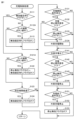
以下、この実施の形態での制御について説明する。図6は、この実施の形態の充電制御処理の流れを示すフローチャートである。この充電制御処理は、ECU300のCPU310によって、上位の処理から所定周期ごとに呼出されて実行される。
Control in this embodiment will be explained below. FIG. 6 is a flowchart showing the flow of charging control processing in this embodiment. This charging control process is called and executed at predetermined intervals by the
図6を参照して、CPU310は、無効確定待ちフラグがオン状態であるか否かを判断する(ステップS111)。無効確定待ちフラグは、充電停止スイッチ301による停止操作が無効化された状態とするかを待っている状態であるか否かを示すフラグであり、具体的には、所定対象に対する予定されている動作が行われたか、予定されている動作とは異なる特定動作が行われたかの判断を待っている状態であるか否かを示すフラグである。
Referring to FIG. 6,
無効確定待ちフラグがオン状態でない(ステップS111でNO)、つまり、オフ状態であると判断した場合、CPU310は、充電コネクタ410のインレット220への挿入を検知したか否かを判断する(ステップS112)。図5で説明したように、CPU310は、接続信号線L3の電位、つまり、接続信号PISWの電位を検出することによって、充電コネクタ410の嵌合状態を判定することができる。
If it is determined that the invalidation confirmation wait flag is not in the on state (NO in step S111), that is, in the off state, the
充電コネクタ410の挿入を検知した(ステップS112でYES)と判断した場合、CPU310は、無効確定待ちフラグをオン状態にする(ステップS113)。充電コネクタ410の挿入を検知していない(ステップS112でNO)と判断した場合、および、ステップS113の後、CPU310は、実行する処理をステップS131に進める。
If it is determined that insertion of the charging
無効確定待ちフラグがオン状態である(ステップS111でYES)と判断した場合、CPU310は、ステップS112と同様の方法で、充電コネクタ410のインレット220への挿入を検知したか否かを判断する(ステップS121)。
If the
充電コネクタ410の挿入を検知した(ステップS121でYES)と判断した場合、CPU310は、停止無効フラグをオン状態にし、無効確定待ちフラグをオフ状態にして(ステップS122)、実行する処理をステップS131に進める。停止無効フラグは、充電停止スイッチ301による停止操作が無効化された状態であるか否かを示すフラグであり、具体的には、所定対象に対する予定されている動作と異なる特定動作が行われた状態であるか否かを示すフラグである。
If it is determined that insertion of the charging
一方、充電コネクタ410の挿入を検知していない(ステップS121でNO)と判断した場合、CPU310は、無効確定待ちフラグをオン状態としてから所定期間(たとえば、2,3秒から10秒程度の所定秒)が経過したか否かを判断する(ステップS123)。所定期間が経過した(ステップS123でYES)と判断した場合、CPU310は、無効確定待ちフラグをオフ状態とする(ステップS124)。所定期間が経過していない(ステップS123でNO)と判断した場合、および、ステップS124の後、CPU310は、実行する処理をステップS131に進める。
On the other hand, if it is determined that the insertion of the charging
ステップS131に処理が進められると、CPU310は、充電開始条件が成立したか否かを判断する(ステップS131)。充電開始条件は、外部充電を開始させることが可能となるための条件である。充電開始条件は、たとえば、蓄電装置110のSOCが所定上限値未満であり、かつ、外部電源500のコンセント510にプラグ420が接続され、かつ、充電コネクタ410がインレット220に挿入された場合に成立する。なお、急速充電の場合は、さらに、外部充電を開始するための急速充電器の側の操作がユーザによって実行された場合に、充電開始条件が成立する。
When the process proceeds to step S131, the
充電開始条件が成立した(ステップS131でYES)と判断した場合、CPU310は、充電停止スイッチ301から充電停止操作信号STPが入力されているか否かを判断する(ステップS132)。充電停止操作信号STPは、ユーザによって充電停止スイッチ301が押下されている間、入力されるとともに、充電停止スイッチ301が閉故障である場合、入力され続ける。
If it is determined that the charging start condition is satisfied (YES in step S131),
充電停止操作信号STPが入力されている(ステップS132でYES)と判断した場合、CPU310は、停止無効フラグがオン状態であるか否かを判断する(ステップS133)。
If it is determined that the charging stop operation signal STP is input (YES in step S132), the
充電停止操作信号STPが入力されていない(ステップS132でNO)と判断した場合、および、充電停止操作信号STPが入力されたが停止無効フラグがオン状態である(ステップS133でYES)と判断した場合、CPU310は、外部充電を開始するよう制御する(ステップS134)。
If it is determined that the charge stop operation signal STP has not been input (NO in step S132), or if it is determined that the charge stop operation signal STP has been input but the stop invalid flag is in the on state (YES in step S133) If so, the
一方、充電開始条件が成立した(ステップS131でYES)と判断されたときに、充電停止操作信号が入力されている(ステップS132でYES)と判断された場合には、停止無効フラグがオン状態でない(ステップS133でNO)、つまり、オフ状態であると判断された場合は、外部充電は開始されない。 On the other hand, when it is determined that the charging start condition is satisfied (YES in step S131), and it is determined that the charging stop operation signal is input (YES in step S132), the stop invalid flag is in the ON state. If not (NO in step S133), that is, if it is determined that it is in the off state, external charging is not started.
充電開始条件が成立していない(ステップS131でNO)と判断した場合、停止無効フラグがオン状態でない(ステップS133でNO)と判断した場合、および、ステップS134の後、CPU310は、外部充電中であるか否かを判断する(ステップS141)。
If it is determined that the charging start condition is not satisfied (NO in step S131), if it is determined that the stop invalidation flag is not on (NO in step S133), and after step S134, the
外部充電中である(ステップS141でYES)と判断した場合、CPU310は、ステップS132と同様に、充電停止スイッチ301から充電停止操作信号STPが入力されたか否かを判断する(ステップS142)。
If it is determined that external charging is in progress (YES in step S141),
充電停止操作信号STPが入力された(ステップS142でYES)と判断した場合、CPU310は、停止無効フラグがオン状態であるか否かを判断する(ステップS143)。
When determining that the charging stop operation signal STP has been input (YES in step S142), the
停止無効フラグがオン状態でない(ステップS143でNO)、つまり、オフ状態であると判断した場合、CPU310は、外部充電を停止するよう制御する(ステップS144)。
If it is determined that the stop invalid flag is not in the on state (NO in step S143), that is, in the off state, the
一方、外部充電中である(ステップS141でYES)と判断されたときに、充電停止操作信号STPが入力された(ステップS142でYES)と判断された場合であっても、停止無効フラグがオン状態である(ステップS143でYES)と判断された場合は、ステップS144に処理は進められず、外部充電は継続される。 On the other hand, even if it is determined that the charging stop operation signal STP has been input (YES in step S142) when it is determined that external charging is in progress (YES in step S141), the stop invalid flag is turned on. If it is determined that the battery is in the current state (YES in step S143), the process does not proceed to step S144, and external charging continues.
外部充電中でない(ステップS141でNO)と判断した場合、充電停止操作信号STPが入力されていない(ステップS142でNO)と判断した場合、停止無効フラグがオン状態である(ステップS143でYES)と判断した場合、および、ステップS144の後、CPU310は、充電終了条件が成立したか否かを判断する(ステップS151)。充電終了条件は、外部充電を終了させる条件である。充電終了条件は、たとえば、蓄電装置110のSOCが所定上限値に達した場合に成立する。
If it is determined that external charging is not in progress (NO in step S141), and if it is determined that the charging stop operation signal STP has not been input (NO in step S142), the stop invalid flag is on (YES in step S143). If it is determined that this is the case, and after step S144, the
充電終了条件が成立した(ステップS151でYES)と判断した場合、CPU310は、外部充電を停止するよう制御し(ステップS152)、停止無効フラグをオフ状態とする(ステップS153)。
If it is determined that the charging termination condition is satisfied (YES in step S151), the
充電終了条件が成立していない(ステップS151でNO)と判断した場合、および、ステップS153の後、CPU310は、実行する処理をこの充電制御処理の呼出元の上位の処理に戻す。
If it is determined that the charging termination condition is not satisfied (NO in step S151), and after step S153,
このように、第1実施形態においては、ECU300は、インレット220への充電コネクタ410の所定期間内の所定回数の接続および不接続の動作が受付けられたと判断した場合、外部充電を停止させるための停止操作の受付を無効化する。
As described above, in the first embodiment, when the
[第2実施形態]
第1実施形態においては、所定期間内に充電コネクタ410のインレット220への挿入が複数(第1実施形態においては2回)検出された場合(つまり、充電コネクタ410の挿入、抜去および挿入が、順に、所定期間内に行われた場合)に、充電停止スイッチ301による充電を停止させる操作が無効とされるようにした。
[Second embodiment]
In the first embodiment, if insertion of the charging
第2実施形態においては、ラッチ状態を解除するための充電コネクタ410の押しボタン415の操作が、所定期間内に複数回(第2実施形態においては2回)検出された場合に、充電停止スイッチ301による充電を停止させる操作が無効とされるようにする。
In the second embodiment, when the operation of the
図7は、第2実施形態の充電制御処理の流れを示すフローチャートである。図7を参照して、図7の充電制御処理は、図6で説明した第1実施形態の充電制御処理のステップS112およびステップS121を、それぞれ、ステップS112AおよびステップS121Aに変更したものである。 FIG. 7 is a flowchart showing the flow of charging control processing according to the second embodiment. Referring to FIG. 7, the charging control process of FIG. 7 is obtained by changing step S112 and step S121 of the charging control process of the first embodiment described in FIG. 6 to step S112A and step S121A, respectively.
ステップS112AおよびステップS121Aでは、CPU310は、充電コネクタ410のラッチ状態を解除するための押しボタン415の押下操作が検知されたか否かを判断する。図5で説明したように、CPU310は、押しボタン415の操作状態に対応して変化する接続信号線L3の電位、すなわち、接続信号PISWの電位を入力バッファ340で検出することで、押しボタン415が押下操作されたか否かを検知する。
In step S112A and step S121A,
このように、第2実施形態においては、ECU300は、押しボタン415に対する所定期間内の所定回数の解除操作が受付けられたと判断した場合、外部充電を停止させるための停止操作の受付を無効化する。
As described above, in the second embodiment, when the
[第3実施形態]
第3実施形態においては、コネクタロック機構260をロックさせるためのコネクタロックスイッチ177のロック操作が、所定期間内に複数回(第3実施形態においては2回)検出された場合(つまり、コネクタロックスイッチ177のロック操作、アンロック操作、および、ロック操作が、順に、所定期間内に行われた場合)に、充電停止スイッチ301による充電を停止させる操作が無効とされるようにする。
[Third embodiment]
In the third embodiment, when the lock operation of the
図8は、第3実施形態の充電制御処理の流れを示すフローチャートである。図8を参照して、図8の充電制御処理は、図6で説明した第1実施形態の充電制御処理のステップS112およびステップS121を、それぞれ、ステップS112BおよびステップS121Bに変更したものである。 FIG. 8 is a flowchart showing the flow of charging control processing according to the third embodiment. Referring to FIG. 8, the charging control process of FIG. 8 is obtained by changing step S112 and step S121 of the charging control process of the first embodiment described in FIG. 6 to step S112B and step S121B, respectively.
ステップS112BおよびステップS121Bでは、CPU310は、充電コネクタ410をコネクタロック機構260でロックまたはアンロックするためのコネクタロックスイッチ177のロック操作が検知されたか否かを判断する。図1および図2で説明したように、コネクタロックスイッチ177が押下操作されるたびに、CPU310に操作信号が入力される。充電コネクタ410がインレット220に挿入されてから最初に入力されたコネクタロックスイッチ177からの操作信号は、コネクタロック機構260をロックさせるための操作信号とされる。
In step S112B and step S121B,
このように、第3実施形態においては、ECU300は、コネクタロックスイッチ177に対する所定期間内の所定回数の切替操作が受付けられたと判断した場合、外部充電を停止させるための停止操作の受付を無効化する。
As described above, in the third embodiment, when the
[変形例]
(1) 前述した実施の形態において、車両100は、プラグインハイブリッド車両であることとした。しかし、これに限定されず、車両100は、外部から車載の蓄電装置110に充電する外部充電が可能な車両であればよく、たとえば、電気自動車であってもよいし、燃料電池自動車であってもよい。
[Modified example]
(1) In the embodiment described above,
(2) 前述した実施の形態において、所定対象に対する予定されている動作とは異なる特定動作が受付けられたと判断された場合に、外部充電を停止させるための停止操作の受付を無効化するようにした。 (2) In the embodiment described above, when it is determined that a specific operation different from the scheduled operation for a predetermined object has been accepted, reception of a stop operation for stopping external charging is disabled. did.
具体的には、第1実施形態においては、所定対象は、充電コネクタ410である。所定対象に対する予定されている動作は、充電コネクタ410のインレット220への通常態様での挿入(具体的には、所定期間内に1回の挿入)である。特定動作は、図6で示したような、充電コネクタ410のインレット220への特定態様での挿入(具体的には、所定期間内に複数回の挿入)である。
Specifically, in the first embodiment, the predetermined target is the charging
第2実施形態においては、所定対象は、ラッチ状態を解除するための充電コネクタ410の押しボタン415である。所定対象に対する予定されている動作は、押しボタン415の通常態様での操作(具体的には、所定期間内に1回の操作)である。特定動作は、図7で示したような、押しボタン415の特定態様での操作(具体的には、所定期間内に複数回の操作)である。
In the second embodiment, the predetermined object is the
第3実施形態においては、所定対象は、充電コネクタ410をコネクタロック機構260でロックまたはアンロックするためのコネクタロックスイッチ177である。所定対象に対する予定されている動作は、コネクタロックスイッチ177の通常態様での操作(具体的には、所定期間内に1回の操作)である。特定動作は、図8で示したような、コネクタロックスイッチ177の特定態様での操作(具体的には、所定期間内に複数回のロック操作)である。
In the third embodiment, the predetermined target is a
しかし、これに限定されず、所定対象および特定動作は、それぞれ、他の所定対象および他の特定動作であってもよく、たとえば、所定対象が充電リッド222であり、特定動作が充電リッド222に対する特定態様での動作(たとえば、所定期間内での複数回の開放動作)であってもよい。なお、充電リッド222に対する予定されている動作は、所定期間内での1回の開放動作である。
However, the predetermined target and the specific action may be other predetermined targets and other specific actions, respectively. For example, the predetermined target is the charging
(3) 前述した実施の形態においては、特定動作が受付けられたと判断された場合、図6~図8のステップS122で示した処理により停止無効フラグがオン状態とされることで、外部充電の停止操作の受付が、ソフトウェア的に無効化されるようにした。しかし、これに限定されず、充電停止操作信号STPがCPU310に入力可能な状態と入力不能な状態とを切替可能な切替回路が設けられ、特定動作が受付けられた場合に、当該切替回路が入力不能な状態に切替えられることで、外部充電の停止操作の受付が、ハードウェア的に無効化されるようにしてもよい。
(3) In the embodiment described above, when it is determined that the specific operation has been accepted, the stop invalidation flag is turned on by the process shown in step S122 of FIGS. 6 to 8, thereby disabling external charging. Acceptance of stop operations is now disabled by software. However, the present invention is not limited to this, and a switching circuit capable of switching between a state in which the charging stop operation signal STP can be input to the
(4) 前述した実施の形態においては、図6から図8で示したように、特定動作が、所定対象に対する予定されている動作とは異なる動作であることとした。しかし、これに限定されず、所定対象は、車両100に予め設けられた構成であってもよいし、特定動作を受付けるために車両100に設けられた構成であってもよい(なお、この場合は、特定動作が所定対象に対する予定されている動作である)。また、特定動作は、所定対象に対する動作でないこととしてもよいし、車両100によって検知可能な他のどのような動作であってもよい。
(4) In the embodiments described above, as shown in FIGS. 6 to 8, the specific motion is a motion different from the motion scheduled for the predetermined object. However, the predetermined target is not limited to this, and may be a configuration provided in the
(5) 前述した実施の形態においては、図6から図8のステップS112,ステップS121,ステップS112A,ステップS121A,ステップS112B,ステップS121Bで示したように、ECU300が、充電停止スイッチ301での停止操作と異なる特定動作が受付けられたかを判断するようにした。 (5) In the embodiment described above, as shown in steps S112, S121, S112A, S121A, S112B, and S121B in FIGS. It is now determined whether a specific action different from the operation is accepted.
しかし、これに限定されず、停止操作と異なる特定動作が受付けられたかを判断する特定動作判断部を、ECU300とは別に設けるようにしてもよい。この場合、特定動作判断部は、特定動作が受付けられたか否かの判断結果を示す情報を、ECU300に送信するようにする。なお、前述した第1実施形態から第3実施形態は、ECU300が特定動作判断部を含んでいると考えることができる。
However, the present invention is not limited to this, and a specific operation determination unit that determines whether a specific operation different from a stop operation has been accepted may be provided separately from
図9は、変形例の外部充電が可能な車両の第1の全体ブロック図である。図9を参照して、第1実施形態においては、特定動作判断部390Aは、接続信号PISWの電位を検出することによって、充電コネクタ410の嵌合状態を判定し、充電コネクタ410の挿入が複数回、検出された場合に、特定動作が受付けられたと判断し、特定動作が受付けられたか否かの判断結果を示す信号を、ECU300に送信する。
FIG. 9 is a first overall block diagram of a modified vehicle capable of external charging. Referring to FIG. 9, in the first embodiment, the specific
再び図9を参照して、第2実施形態においては、特定動作判断部390Aは、接続信号PISWの電位を検出することによって、押しボタン415が押下操作されたかを判定し、押しボタン415に対する所定期間内の所定回数の解除操作が受付けられた場合に、特定動作が受付けられたと判断し、特定動作が受付けられたか否かの判断結果を示す信号を、ECU300に送信する。
Referring again to FIG. 9, in the second embodiment, the specific
図10は、変形例の外部充電が可能な車輌の第2の全体ブロック図である。図10を参照して、第3実施形態においては、特定動作判断部390Bは、コネクタロック機構260をロックさせるためのコネクタロックスイッチ177のロック操作が、所定期間内に複数回、検出された場合に、特定動作が受付けられたと判断し、特定動作が受付けられたか否かの判断結果を示す信号を、ECU300に送信する。
FIG. 10 is a second overall block diagram of a modified vehicle capable of external charging. Referring to FIG. 10, in the third embodiment, if a locking operation of
[まとめ]
(1) 図1から図5で示したように、車両100は、外部充電を停止させるための停止操作を受付ける充電停止スイッチ301と、充電停止スイッチ301で停止操作が受付けられたことを条件として外部充電を停止させるECU300とを備える。図6から図8で示したように、ECU300は、充電停止スイッチ301での停止操作と異なる特定動作が受付けられたことを判断し(ステップS112,ステップS121,ステップS112A,ステップS121A,ステップS112B,ステップS121B)、特定動作が受付けられたと判断した場合、停止操作の受付を無効化する(ステップS122)。
[summary]
(1) As shown in FIGS. 1 to 5, the
これにより、外部充電を停止させるための停止操作と異なる特定動作が受付けられたと判断された場合、充電停止スイッチ301による停止操作の受付が無効化される。その結果、外部充電を停止させる停止操作を受付ける充電停止スイッチ301が故障した場合であっても外部充電をすることができる。
As a result, if it is determined that a specific operation different from a stop operation for stopping external charging has been accepted, acceptance of the stop operation by the charging
(2) 図6から図8で示したように、特定動作は、所定対象に対する予定されている動作とは異なる動作である。これにより、所定対象に対する予定されている動作と異なる特定動作が受付けられたと判断された場合、充電停止スイッチ301による停止操作の受付が無効化される。このため、車両に既に備えられた所定対象に対する動作として特定動作を受付けることができる。その結果、特別な構成を設ける必要無く、特定動作を受付けることができる。
(2) As shown in FIGS. 6 to 8, the specific action is a different action from the planned action for the predetermined object. As a result, if it is determined that a specific action different from the scheduled action for the predetermined object has been accepted, acceptance of a stop operation by the charging
(3) 図1から図5で示したように、車両100は、外部からの充電用の充電コネクタ410を接続可能なインレット220を備える。図6で示したように、ECU300は、インレット220への充電コネクタ410の接続を検知し(ステップS112,ステップS121)、所定対象は、充電コネクタ410であり、特定動作は、所定期間内の所定回数の所定対象の接続および不接続の動作である。
(3) As shown in FIGS. 1 to 5, the
これにより、所定期間内の所定回数の充電コネクタ410の接続および不接続の動作が、特定動作として受付けられたと判断された場合、充電停止スイッチ301による停止操作の受付が無効化される。このため、車両100に既に備えられた充電コネクタ410に対する動作として特定動作を受付けることができる。その結果、特別な構成を設ける必要無く、特定動作を受付けることができる。
As a result, if it is determined that the operation of connecting and disconnecting the charging connector 410 a predetermined number of times within a predetermined period has been accepted as a specific operation, acceptance of a stop operation by the charging
(4) 図1から図5で示したように、車両100は、外部からの充電用の充電コネクタ410を接続可能なインレット220と、インレット220に接続された充電コネクタ410が外れないラッチ状態とするラッチ機構(リンク416の凸部と、インレット220の突起221との組合せ)と、ラッチ機構によるラッチ状態を解除するための解除操作を受付ける押しボタン415とをさらに備える。図7で示したように、所定対象は、押しボタン415であり、特定動作は、所定対象に対する所定期間内の所定回数の解除操作である。
(4) As shown in FIGS. 1 to 5, the
これにより、押しボタン415に対する所定期間内の所定回数の解除操作が、特定動作として受付けられたと判断された場合、充電停止スイッチ301による停止操作の受付が無効化される。このため、車両100に既に備えられた押しボタン415に対する動作として特定動作を受付けることができる。その結果、特別な構成を設ける必要無く、特定動作を受付けることができる。
As a result, when it is determined that a predetermined number of release operations on the
(5) 図1から図5で示したように、車両100は、外部からの充電用の充電コネクタ410を接続可能なインレット220と、インレット220に接続された充電コネクタ410が外れないロック状態と外すことが可能なアンロック状態とを切替えるコネクタロック機構260と、コネクタロック機構260によるロック状態およびアンロック状態との切替操作を受付けるコネクタロックスイッチ177とをさらに備える。図8で示したように、所定対象は、コネクタロックスイッチ177であり、特定動作は、所定対象に対する所定期間内の所定回数の切替操作である。
(5) As shown in FIGS. 1 to 5, the
これにより、コネクタロックスイッチ177に対する所定期間内の所定回数の切替操作が、特定動作として受付けられたと判断された場合、充電停止スイッチ301による停止操作の受付が無効化される。このため、車両100に既に備えられたコネクタロックスイッチ177に対する動作として特定動作を受付けることができる。その結果、特別な構成を設ける必要無く、特定動作を受付けることができる。
As a result, when it is determined that a predetermined number of switching operations on the
今回開示された実施の形態はすべての点で例示であって制限的なものではないと考えられるべきである。本開示の範囲は上記した説明ではなくて特許請求の範囲によって示され、特許請求の範囲と均等の意味および範囲内でのすべての変更が含まれることが意図される。 The embodiments disclosed this time should be considered to be illustrative in all respects and not restrictive. The scope of the present disclosure is indicated by the claims rather than the above description, and it is intended that all changes within the meaning and range equivalent to the claims are included.
100 車両、110 蓄電装置、120 PCU、121 コンバータ、122,123 インバータ、130,135 モータジェネレータ、140 動力伝達ギヤ、150 駆動輪、160 エンジン、177 コネクタロックスイッチ、200 電力変換装置、220 インレット、221 突起、222 充電リッド、230,473,481 電圧センサ、260 コネクタロック機構、261 アクチュエータ、262 ロックバー、263 押圧力検出センサ、300 ECU、301 充電停止スイッチ、310 CPU、320 抵抗回路、330,340 入力バッファ、350 電源ノード、360 アース、390A,390B 特定動作判断部、400 充電ケーブル、410 充電コネクタ、411 接続検知回路、413 接続部、414 バネ、415 押しボタン、416 リンク、417 軸、420 プラグ、440 ケーブル部、450 CCIDリレー、460 CCID制御部、470 コントロールパイロット回路、471 電磁コイル、472 発振回路、480 漏電検出器、482 電流センサ、500 外部電源、510 コンセント。 100 vehicle, 110 power storage device, 120 PCU, 121 converter, 122, 123 inverter, 130, 135 motor generator, 140 power transmission gear, 150 drive wheel, 160 engine, 177 connector lock switch, 200 power converter, 220 inlet, 221 Projection, 222 Charging lid, 230,473,481 Voltage sensor, 260 Connector locking mechanism, 261 Actuator, 262 Lock bar, 263 Pressure force detection sensor, 300 ECU, 301 Charging stop switch, 310 CPU, 320 Resistance circuit, 330,340 Input buffer, 350 power supply node, 360 earth, 390A, 390B specific operation determination section, 400 charging cable, 410 charging connector, 411 connection detection circuit, 413 connection section, 414 spring, 415 push button, 416 link, 417 axis, 420 plug , 440 cable section, 450 CCID relay, 460 CCID control section, 470 control pilot circuit, 471 electromagnetic coil, 472 oscillation circuit, 480 earth leakage detector, 482 current sensor, 500 external power supply, 510 outlet.
Claims (3)
前記外部充電を停止させるための停止操作を受付ける停止操作部と、
前記停止操作部で前記停止操作が受付けられたことを条件として前記外部充電を停止させる制御部と、
外部からの充電用の充電コネクタを接続可能なインレットと、
前記インレットへの前記充電コネクタの接続を検知する検知部とを備え、
前記制御部は、前記停止操作部での前記停止操作と異なる特定動作が受付けられた場合、前記停止操作の受付を無効化し、
前記特定動作は、所定対象に対する予定されている動作とは異なる動作であり、
前記所定対象は、前記充電コネクタであり、
前記特定動作は、所定期間内の所定回数の前記所定対象の接続および不接続の動作である、車両。 A vehicle capable of external charging for charging an on-vehicle power storage device from the outside,
a stop operation section that accepts a stop operation for stopping the external charging;
a control unit that stops the external charging on the condition that the stop operation is accepted by the stop operation unit ;
An inlet to which a charging connector for external charging can be connected,
a detection unit that detects connection of the charging connector to the inlet ,
The control unit disables reception of the stop operation when a specific operation different from the stop operation at the stop operation unit is received,
The specific action is a different action from a planned action for a predetermined target,
The predetermined target is the charging connector,
The vehicle , wherein the specific operation is an operation of connecting and disconnecting the predetermined object a predetermined number of times within a predetermined period .
前記外部充電を停止させるための停止操作を受付ける停止操作部と、
前記停止操作部で前記停止操作が受付けられたことを条件として前記外部充電を停止させる制御部と、
外部からの充電用の充電コネクタを接続可能なインレットと、
前記インレットに接続された前記充電コネクタが外れないラッチ状態とするラッチ機構と、
前記ラッチ機構によるラッチ状態を解除するための解除操作を受付ける解除操作部とを備え、
前記制御部は、前記停止操作部での前記停止操作と異なる特定動作が受付けられた場合、前記停止操作の受付を無効化し、
前記特定動作は、所定対象に対する予定されている動作とは異なる動作であり、
前記所定対象は、前記解除操作部であり、
前記特定動作は、前記所定対象に対する所定期間内の所定回数の前記解除操作である、車両。 A vehicle capable of external charging for charging an on-vehicle power storage device from the outside,
a stop operation section that accepts a stop operation for stopping the external charging;
a control unit that stops the external charging on the condition that the stop operation is accepted by the stop operation unit ;
An inlet to which a charging connector for external charging can be connected,
a latch mechanism that puts the charging connector connected to the inlet in a latched state that prevents it from coming off;
a release operation section that accepts a release operation for releasing the latched state by the latch mechanism ,
The control unit disables reception of the stop operation when a specific operation different from the stop operation at the stop operation unit is received,
The specific action is a different action from a planned action for a predetermined target,
The predetermined target is the release operation section,
In the vehicle , the specific operation is the release operation performed on the predetermined target a predetermined number of times within a predetermined period .
前記外部充電を停止させるための停止操作を受付ける停止操作部と、
前記停止操作部で前記停止操作が受付けられたことを条件として前記外部充電を停止させる制御部と、
外部からの充電用の充電コネクタを接続可能なインレットと、
前記インレットに接続された前記充電コネクタが外れないロック状態と外すことが可能なアンロック状態とを切替えるロック機構と、
前記ロック機構によるロック状態およびアンロック状態との切替操作を受付ける切替操作部とを備え、
前記制御部は、前記停止操作部での前記停止操作と異なる特定動作が受付けられた場合、前記停止操作の受付を無効化し、
前記特定動作は、所定対象に対する予定されている動作とは異なる動作であり、
前記所定対象は、前記切替操作部であり、
前記特定動作は、前記所定対象に対する所定期間内の所定回数の前記切替操作である、車両。 A vehicle capable of external charging for charging an on-vehicle power storage device from the outside,
a stop operation section that accepts a stop operation for stopping the external charging;
a control unit that stops the external charging on the condition that the stop operation is accepted by the stop operation unit ;
An inlet to which a charging connector for external charging can be connected,
a locking mechanism that switches between a locked state in which the charging connector connected to the inlet cannot be removed and an unlocked state in which it can be removed;
a switching operation section that accepts a switching operation between a locked state and an unlocked state by the locking mechanism ,
The control unit disables reception of the stop operation when a specific operation different from the stop operation at the stop operation unit is received,
The specific action is a different action from a planned action for a predetermined target,
The predetermined target is the switching operation section,
The vehicle , wherein the specific operation is the switching operation for the predetermined object a predetermined number of times within a predetermined period .
Priority Applications (5)
| Application Number | Priority Date | Filing Date | Title |
|---|---|---|---|
| JP2020016815A JP7380272B2 (en) | 2020-02-04 | 2020-02-04 | vehicle |
| US17/164,064 US11358485B2 (en) | 2020-02-04 | 2021-02-01 | Vehicle |
| DE102021102447.1A DE102021102447A1 (en) | 2020-02-04 | 2021-02-03 | vehicle |
| CN202110151468.0A CN113212241B (en) | 2020-02-04 | 2021-02-03 | Vehicle with a vehicle body having a vehicle body support |
| US17/741,996 US11738655B2 (en) | 2020-02-04 | 2022-05-11 | Vehicle |
Applications Claiming Priority (1)
| Application Number | Priority Date | Filing Date | Title |
|---|---|---|---|
| JP2020016815A JP7380272B2 (en) | 2020-02-04 | 2020-02-04 | vehicle |
Publications (2)
| Publication Number | Publication Date |
|---|---|
| JP2021125933A JP2021125933A (en) | 2021-08-30 |
| JP7380272B2 true JP7380272B2 (en) | 2023-11-15 |
Family
ID=76854051
Family Applications (1)
| Application Number | Title | Priority Date | Filing Date |
|---|---|---|---|
| JP2020016815A Active JP7380272B2 (en) | 2020-02-04 | 2020-02-04 | vehicle |
Country Status (4)
| Country | Link |
|---|---|
| US (2) | US11358485B2 (en) |
| JP (1) | JP7380272B2 (en) |
| CN (1) | CN113212241B (en) |
| DE (1) | DE102021102447A1 (en) |
Families Citing this family (6)
| Publication number | Priority date | Publication date | Assignee | Title |
|---|---|---|---|---|
| JP7268566B2 (en) * | 2019-10-09 | 2023-05-08 | トヨタ自動車株式会社 | vehicle |
| CN114006223A (en) * | 2021-10-28 | 2022-02-01 | 深圳市泰格莱精密电子有限公司 | Novel charging connector and electric automobile |
| US11852689B2 (en) | 2021-12-28 | 2023-12-26 | Beta Air, Llc | Connector for charging an electric aircraft and a method of use for a connector for charging an electric aircraft |
| US11535110B1 (en) * | 2021-12-28 | 2022-12-27 | Beta Air, Llc | Systems and methods for a locking electric aircraft connector |
| US20230322087A1 (en) * | 2022-04-08 | 2023-10-12 | Ford Global Technologies, Llc | Isolation fault detection on dc charge bus |
| US11718197B1 (en) * | 2022-08-09 | 2023-08-08 | Beta Air, Llc | Apparatus for authorizing an electric aircraft to charge at a charging structure and a method for its use |
Citations (2)
| Publication number | Priority date | Publication date | Assignee | Title |
|---|---|---|---|---|
| JP2011072104A (en) | 2009-09-25 | 2011-04-07 | Nitto Electric Works Ltd | Charging device for vehicle |
| JP2014241670A (en) | 2013-06-11 | 2014-12-25 | シャープ株式会社 | Electric power charging and supply system |
Family Cites Families (40)
| Publication number | Priority date | Publication date | Assignee | Title |
|---|---|---|---|---|
| JP2008046751A (en) * | 2006-08-11 | 2008-02-28 | Toyota Motor Corp | Photovoltaic power generation system, vehicle, control method for photovoltaic power generation system, and computer readable recording medium with program for making computer perform its control method reocrded |
| JP4894646B2 (en) * | 2007-06-15 | 2012-03-14 | トヨタ自動車株式会社 | Charging device and charging system |
| JP2009089452A (en) * | 2007-09-27 | 2009-04-23 | Denso Corp | Charging system |
| US8054048B2 (en) * | 2007-10-04 | 2011-11-08 | GM Global Technology Operations LLC | Power grid load management for plug-in vehicles |
| JP4407753B2 (en) * | 2008-01-15 | 2010-02-03 | トヨタ自動車株式会社 | Electric vehicle charging system |
| US20110258112A1 (en) * | 2008-10-31 | 2011-10-20 | Leviton Manufacturing Company Inc. | System and method for charging a vehicle |
| JP5471530B2 (en) * | 2010-02-03 | 2014-04-16 | トヨタ自動車株式会社 | vehicle |
| JP5438824B2 (en) * | 2010-05-11 | 2014-03-12 | パナソニック株式会社 | Power control apparatus and grid interconnection system including the same |
| JP5914980B2 (en) * | 2010-06-09 | 2016-05-11 | 日産自動車株式会社 | Charge control apparatus and method |
| US8779719B2 (en) * | 2010-07-05 | 2014-07-15 | Toyota Jidosha Kabushiki Kaisha | Charging control apparatus |
| US9230761B2 (en) * | 2010-07-21 | 2016-01-05 | Volvo Construction Equipment Ab | Emergency stop system for a hybrid excavator |
| JP5369067B2 (en) * | 2010-08-25 | 2013-12-18 | 三菱自動車工業株式会社 | Charge control device |
| JP5533788B2 (en) * | 2010-12-24 | 2014-06-25 | 株式会社日立製作所 | Charge control system |
| JP5522115B2 (en) * | 2011-04-27 | 2014-06-18 | 株式会社デンソー | Charge control device |
| JP6012144B2 (en) * | 2011-05-20 | 2016-10-25 | パナソニックエコソリューションズ電路株式会社 | Charge control system |
| JP5218800B2 (en) * | 2011-10-31 | 2013-06-26 | トヨタ自動車株式会社 | VEHICLE HAVING POWER STORAGE UNIT AND CHARGE / DISCHARGE SYSTEM INCLUDING THE VEHICLE AND ENERGY MANAGEMENT |
| US9431930B2 (en) * | 2011-12-28 | 2016-08-30 | Doosan Infracore Co., Ltd. | Emergency stop method for hybrid construction equipment and brake control device |
| JP5678910B2 (en) | 2012-03-09 | 2015-03-04 | トヨタ自動車株式会社 | Power supply |
| EP2958222A4 (en) * | 2013-02-13 | 2016-05-04 | Panasonic Ip Man Co Ltd | Power supply device, on-board power supply device, and electric automobile |
| JP5761229B2 (en) | 2013-02-26 | 2015-08-12 | トヨタ自動車株式会社 | Vehicle charging device |
| EP2842793B1 (en) * | 2013-09-02 | 2021-03-03 | Volvo Car Corporation | Method for controlling charging of a hybrid or electric vehicle |
| JP6112033B2 (en) * | 2014-02-12 | 2017-04-12 | トヨタ自動車株式会社 | Electric power transfer control device |
| DE102014209210A1 (en) * | 2014-05-15 | 2015-11-19 | Volkswagen Aktiengesellschaft | Controlling a locking device of an electrical charging connection |
| US20160380440A1 (en) * | 2015-06-26 | 2016-12-29 | TEQ Charging, Inc. | Electric charging power management |
| JP6421095B2 (en) * | 2015-08-05 | 2018-11-07 | 株式会社オートネットワーク技術研究所 | Repeater |
| US11479139B2 (en) * | 2015-09-11 | 2022-10-25 | Invertedpower Pty Ltd | Methods and systems for an integrated charging system for an electric vehicle |
| US10471846B2 (en) * | 2016-08-23 | 2019-11-12 | Pismo Labs Technology Limited | Methods and systems for supplying electricity to multiple loads with current measurements |
| JP6477670B2 (en) * | 2016-11-15 | 2019-03-06 | トヨタ自動車株式会社 | Power feeding system and vehicle |
| JP6772872B2 (en) * | 2017-02-06 | 2020-10-21 | トヨタ自動車株式会社 | vehicle |
| CN107128178B (en) * | 2017-04-05 | 2019-06-28 | 中通客车控股股份有限公司 | A kind of electric motor coach charge protection system and method |
| CN107895974A (en) * | 2017-04-25 | 2018-04-10 | 厦门深蓝动力科技有限公司 | A kind of electric automobile energy storage mobile charging stake and system |
| CN206884777U (en) * | 2017-05-24 | 2018-01-16 | 乐山一拉得电网自动化有限公司 | A kind of charging pile antitheft for Rechargeable vehicle charging wire |
| KR102516435B1 (en) * | 2017-10-17 | 2023-03-31 | 엘지이노텍 주식회사 | Electric Vehicle Charging Controller |
| CN108725244B (en) * | 2018-05-29 | 2023-08-08 | 中通客车股份有限公司 | Self-adaptive charging auxiliary power supply system of electric motor coach |
| JP2020016815A (en) | 2018-07-27 | 2020-01-30 | セイコーエプソン株式会社 | Electrophoretic device, electronic device, and method of manufacturing electrophoretic device |
| JP7200599B2 (en) * | 2018-10-23 | 2023-01-10 | トヨタ自動車株式会社 | vehicle |
| KR20200091519A (en) * | 2019-01-22 | 2020-07-31 | 현대자동차주식회사 | Vehicle, and Method for controlling the vehicle |
| KR102373345B1 (en) * | 2019-10-18 | 2022-03-14 | 주식회사 나인와트 | Electric car charging system |
| GB2597739A (en) * | 2020-07-31 | 2022-02-09 | Siemens Mobility Ltd | Method of charging of an electric vehicle |
| CN113561830A (en) * | 2021-07-26 | 2021-10-29 | 阳光电源股份有限公司 | Emergency stop switch protection method and device for charging pile and charging pile |
-
2020
- 2020-02-04 JP JP2020016815A patent/JP7380272B2/en active Active
-
2021
- 2021-02-01 US US17/164,064 patent/US11358485B2/en active Active
- 2021-02-03 CN CN202110151468.0A patent/CN113212241B/en active Active
- 2021-02-03 DE DE102021102447.1A patent/DE102021102447A1/en active Pending
-
2022
- 2022-05-11 US US17/741,996 patent/US11738655B2/en active Active
Patent Citations (2)
| Publication number | Priority date | Publication date | Assignee | Title |
|---|---|---|---|---|
| JP2011072104A (en) | 2009-09-25 | 2011-04-07 | Nitto Electric Works Ltd | Charging device for vehicle |
| JP2014241670A (en) | 2013-06-11 | 2014-12-25 | シャープ株式会社 | Electric power charging and supply system |
Also Published As
| Publication number | Publication date |
|---|---|
| US11738655B2 (en) | 2023-08-29 |
| DE102021102447A1 (en) | 2021-08-05 |
| CN113212241B (en) | 2024-04-09 |
| JP2021125933A (en) | 2021-08-30 |
| US20210237605A1 (en) | 2021-08-05 |
| CN113212241A (en) | 2021-08-06 |
| US20220266711A1 (en) | 2022-08-25 |
| US11358485B2 (en) | 2022-06-14 |
Similar Documents
| Publication | Publication Date | Title |
|---|---|---|
| JP7380272B2 (en) | vehicle | |
| JP5758746B2 (en) | Power supply connector, vehicle, and vehicle control method | |
| JP5288004B2 (en) | vehicle | |
| US9090169B2 (en) | Adapter and vehicle for performing power feeding using adapter | |
| JP5029783B2 (en) | Charging system | |
| JP5376057B2 (en) | Vehicle and charging system, and vehicle control method | |
| JP5099279B1 (en) | Power supply connector, vehicle, and method for recognizing power supply connector | |
| JP5077376B2 (en) | vehicle | |
| JP5679071B2 (en) | Power supply system and power supply device | |
| JP2011035975A (en) | Vehicle and vehicle control method | |
| JP5682537B2 (en) | Power supply system and power supply device | |
| JP2012162176A (en) | Vehicle and vehicle control method | |
| JP5994930B2 (en) | vehicle | |
| JP6003767B2 (en) | Power transmission cable |
Legal Events
| Date | Code | Title | Description |
|---|---|---|---|
| A621 | Written request for application examination |
Free format text: JAPANESE INTERMEDIATE CODE: A621 Effective date: 20220317 |
|
| A131 | Notification of reasons for refusal |
Free format text: JAPANESE INTERMEDIATE CODE: A131 Effective date: 20230530 |
|
| A521 | Request for written amendment filed |
Free format text: JAPANESE INTERMEDIATE CODE: A523 Effective date: 20230706 |
|
| TRDD | Decision of grant or rejection written | ||
| A01 | Written decision to grant a patent or to grant a registration (utility model) |
Free format text: JAPANESE INTERMEDIATE CODE: A01 Effective date: 20231003 |
|
| A61 | First payment of annual fees (during grant procedure) |
Free format text: JAPANESE INTERMEDIATE CODE: A61 Effective date: 20231016 |
|
| R151 | Written notification of patent or utility model registration |
Ref document number: 7380272 Country of ref document: JP Free format text: JAPANESE INTERMEDIATE CODE: R151 |