JP6477670B2 - Power feeding system and vehicle - Google Patents
Power feeding system and vehicle Download PDFInfo
- Publication number
- JP6477670B2 JP6477670B2 JP2016222299A JP2016222299A JP6477670B2 JP 6477670 B2 JP6477670 B2 JP 6477670B2 JP 2016222299 A JP2016222299 A JP 2016222299A JP 2016222299 A JP2016222299 A JP 2016222299A JP 6477670 B2 JP6477670 B2 JP 6477670B2
- Authority
- JP
- Japan
- Prior art keywords
- power supply
- communication
- power
- vehicle
- mobile terminal
- Prior art date
- Legal status (The legal status is an assumption and is not a legal conclusion. Google has not performed a legal analysis and makes no representation as to the accuracy of the status listed.)
- Active
Links
Images


Classifications
-
- H—ELECTRICITY
- H02—GENERATION; CONVERSION OR DISTRIBUTION OF ELECTRIC POWER
- H02J—CIRCUIT ARRANGEMENTS OR SYSTEMS FOR SUPPLYING OR DISTRIBUTING ELECTRIC POWER; SYSTEMS FOR STORING ELECTRIC ENERGY
- H02J7/00—Circuit arrangements for charging or depolarising batteries or for supplying loads from batteries
- H02J7/14—Circuit arrangements for charging or depolarising batteries or for supplying loads from batteries for charging batteries from dynamo-electric generators driven at varying speed, e.g. on vehicle
- H02J7/1415—Circuit arrangements for charging or depolarising batteries or for supplying loads from batteries for charging batteries from dynamo-electric generators driven at varying speed, e.g. on vehicle with a generator driven by a prime mover other than the motor of a vehicle
-
- B—PERFORMING OPERATIONS; TRANSPORTING
- B60—VEHICLES IN GENERAL
- B60L—PROPULSION OF ELECTRICALLY-PROPELLED VEHICLES; SUPPLYING ELECTRIC POWER FOR AUXILIARY EQUIPMENT OF ELECTRICALLY-PROPELLED VEHICLES; ELECTRODYNAMIC BRAKE SYSTEMS FOR VEHICLES IN GENERAL; MAGNETIC SUSPENSION OR LEVITATION FOR VEHICLES; MONITORING OPERATING VARIABLES OF ELECTRICALLY-PROPELLED VEHICLES; ELECTRIC SAFETY DEVICES FOR ELECTRICALLY-PROPELLED VEHICLES
- B60L53/00—Methods of charging batteries, specially adapted for electric vehicles; Charging stations or on-board charging equipment therefor; Exchange of energy storage elements in electric vehicles
- B60L53/60—Monitoring or controlling charging stations
-
- B—PERFORMING OPERATIONS; TRANSPORTING
- B60—VEHICLES IN GENERAL
- B60L—PROPULSION OF ELECTRICALLY-PROPELLED VEHICLES; SUPPLYING ELECTRIC POWER FOR AUXILIARY EQUIPMENT OF ELECTRICALLY-PROPELLED VEHICLES; ELECTRODYNAMIC BRAKE SYSTEMS FOR VEHICLES IN GENERAL; MAGNETIC SUSPENSION OR LEVITATION FOR VEHICLES; MONITORING OPERATING VARIABLES OF ELECTRICALLY-PROPELLED VEHICLES; ELECTRIC SAFETY DEVICES FOR ELECTRICALLY-PROPELLED VEHICLES
- B60L50/00—Electric propulsion with power supplied within the vehicle
- B60L50/10—Electric propulsion with power supplied within the vehicle using propulsion power supplied by engine-driven generators, e.g. generators driven by combustion engines
- B60L50/15—Electric propulsion with power supplied within the vehicle using propulsion power supplied by engine-driven generators, e.g. generators driven by combustion engines with additional electric power supply
-
- B—PERFORMING OPERATIONS; TRANSPORTING
- B60—VEHICLES IN GENERAL
- B60L—PROPULSION OF ELECTRICALLY-PROPELLED VEHICLES; SUPPLYING ELECTRIC POWER FOR AUXILIARY EQUIPMENT OF ELECTRICALLY-PROPELLED VEHICLES; ELECTRODYNAMIC BRAKE SYSTEMS FOR VEHICLES IN GENERAL; MAGNETIC SUSPENSION OR LEVITATION FOR VEHICLES; MONITORING OPERATING VARIABLES OF ELECTRICALLY-PROPELLED VEHICLES; ELECTRIC SAFETY DEVICES FOR ELECTRICALLY-PROPELLED VEHICLES
- B60L50/00—Electric propulsion with power supplied within the vehicle
- B60L50/50—Electric propulsion with power supplied within the vehicle using propulsion power supplied by batteries or fuel cells
-
- B—PERFORMING OPERATIONS; TRANSPORTING
- B60—VEHICLES IN GENERAL
- B60L—PROPULSION OF ELECTRICALLY-PROPELLED VEHICLES; SUPPLYING ELECTRIC POWER FOR AUXILIARY EQUIPMENT OF ELECTRICALLY-PROPELLED VEHICLES; ELECTRODYNAMIC BRAKE SYSTEMS FOR VEHICLES IN GENERAL; MAGNETIC SUSPENSION OR LEVITATION FOR VEHICLES; MONITORING OPERATING VARIABLES OF ELECTRICALLY-PROPELLED VEHICLES; ELECTRIC SAFETY DEVICES FOR ELECTRICALLY-PROPELLED VEHICLES
- B60L53/00—Methods of charging batteries, specially adapted for electric vehicles; Charging stations or on-board charging equipment therefor; Exchange of energy storage elements in electric vehicles
- B60L53/10—Methods of charging batteries, specially adapted for electric vehicles; Charging stations or on-board charging equipment therefor; Exchange of energy storage elements in electric vehicles characterised by the energy transfer between the charging station and the vehicle
- B60L53/14—Conductive energy transfer
-
- B—PERFORMING OPERATIONS; TRANSPORTING
- B60—VEHICLES IN GENERAL
- B60L—PROPULSION OF ELECTRICALLY-PROPELLED VEHICLES; SUPPLYING ELECTRIC POWER FOR AUXILIARY EQUIPMENT OF ELECTRICALLY-PROPELLED VEHICLES; ELECTRODYNAMIC BRAKE SYSTEMS FOR VEHICLES IN GENERAL; MAGNETIC SUSPENSION OR LEVITATION FOR VEHICLES; MONITORING OPERATING VARIABLES OF ELECTRICALLY-PROPELLED VEHICLES; ELECTRIC SAFETY DEVICES FOR ELECTRICALLY-PROPELLED VEHICLES
- B60L53/00—Methods of charging batteries, specially adapted for electric vehicles; Charging stations or on-board charging equipment therefor; Exchange of energy storage elements in electric vehicles
- B60L53/30—Constructional details of charging stations
- B60L53/305—Communication interfaces
-
- B—PERFORMING OPERATIONS; TRANSPORTING
- B60—VEHICLES IN GENERAL
- B60L—PROPULSION OF ELECTRICALLY-PROPELLED VEHICLES; SUPPLYING ELECTRIC POWER FOR AUXILIARY EQUIPMENT OF ELECTRICALLY-PROPELLED VEHICLES; ELECTRODYNAMIC BRAKE SYSTEMS FOR VEHICLES IN GENERAL; MAGNETIC SUSPENSION OR LEVITATION FOR VEHICLES; MONITORING OPERATING VARIABLES OF ELECTRICALLY-PROPELLED VEHICLES; ELECTRIC SAFETY DEVICES FOR ELECTRICALLY-PROPELLED VEHICLES
- B60L53/00—Methods of charging batteries, specially adapted for electric vehicles; Charging stations or on-board charging equipment therefor; Exchange of energy storage elements in electric vehicles
- B60L53/60—Monitoring or controlling charging stations
- B60L53/66—Data transfer between charging stations and vehicles
-
- B—PERFORMING OPERATIONS; TRANSPORTING
- B60—VEHICLES IN GENERAL
- B60L—PROPULSION OF ELECTRICALLY-PROPELLED VEHICLES; SUPPLYING ELECTRIC POWER FOR AUXILIARY EQUIPMENT OF ELECTRICALLY-PROPELLED VEHICLES; ELECTRODYNAMIC BRAKE SYSTEMS FOR VEHICLES IN GENERAL; MAGNETIC SUSPENSION OR LEVITATION FOR VEHICLES; MONITORING OPERATING VARIABLES OF ELECTRICALLY-PROPELLED VEHICLES; ELECTRIC SAFETY DEVICES FOR ELECTRICALLY-PROPELLED VEHICLES
- B60L55/00—Arrangements for supplying energy stored within a vehicle to a power network, i.e. vehicle-to-grid [V2G] arrangements
-
- B—PERFORMING OPERATIONS; TRANSPORTING
- B60—VEHICLES IN GENERAL
- B60L—PROPULSION OF ELECTRICALLY-PROPELLED VEHICLES; SUPPLYING ELECTRIC POWER FOR AUXILIARY EQUIPMENT OF ELECTRICALLY-PROPELLED VEHICLES; ELECTRODYNAMIC BRAKE SYSTEMS FOR VEHICLES IN GENERAL; MAGNETIC SUSPENSION OR LEVITATION FOR VEHICLES; MONITORING OPERATING VARIABLES OF ELECTRICALLY-PROPELLED VEHICLES; ELECTRIC SAFETY DEVICES FOR ELECTRICALLY-PROPELLED VEHICLES
- B60L58/00—Methods or circuit arrangements for monitoring or controlling batteries or fuel cells, specially adapted for electric vehicles
- B60L58/10—Methods or circuit arrangements for monitoring or controlling batteries or fuel cells, specially adapted for electric vehicles for monitoring or controlling batteries
- B60L58/12—Methods or circuit arrangements for monitoring or controlling batteries or fuel cells, specially adapted for electric vehicles for monitoring or controlling batteries responding to state of charge [SoC]
- B60L58/13—Maintaining the SoC within a determined range
-
- B—PERFORMING OPERATIONS; TRANSPORTING
- B60—VEHICLES IN GENERAL
- B60W—CONJOINT CONTROL OF VEHICLE SUB-UNITS OF DIFFERENT TYPE OR DIFFERENT FUNCTION; CONTROL SYSTEMS SPECIALLY ADAPTED FOR HYBRID VEHICLES; ROAD VEHICLE DRIVE CONTROL SYSTEMS FOR PURPOSES NOT RELATED TO THE CONTROL OF A PARTICULAR SUB-UNIT
- B60W10/00—Conjoint control of vehicle sub-units of different type or different function
- B60W10/04—Conjoint control of vehicle sub-units of different type or different function including control of propulsion units
- B60W10/06—Conjoint control of vehicle sub-units of different type or different function including control of propulsion units including control of combustion engines
-
- B—PERFORMING OPERATIONS; TRANSPORTING
- B60—VEHICLES IN GENERAL
- B60W—CONJOINT CONTROL OF VEHICLE SUB-UNITS OF DIFFERENT TYPE OR DIFFERENT FUNCTION; CONTROL SYSTEMS SPECIALLY ADAPTED FOR HYBRID VEHICLES; ROAD VEHICLE DRIVE CONTROL SYSTEMS FOR PURPOSES NOT RELATED TO THE CONTROL OF A PARTICULAR SUB-UNIT
- B60W10/00—Conjoint control of vehicle sub-units of different type or different function
- B60W10/24—Conjoint control of vehicle sub-units of different type or different function including control of energy storage means
- B60W10/26—Conjoint control of vehicle sub-units of different type or different function including control of energy storage means for electrical energy, e.g. batteries or capacitors
-
- B—PERFORMING OPERATIONS; TRANSPORTING
- B60—VEHICLES IN GENERAL
- B60W—CONJOINT CONTROL OF VEHICLE SUB-UNITS OF DIFFERENT TYPE OR DIFFERENT FUNCTION; CONTROL SYSTEMS SPECIALLY ADAPTED FOR HYBRID VEHICLES; ROAD VEHICLE DRIVE CONTROL SYSTEMS FOR PURPOSES NOT RELATED TO THE CONTROL OF A PARTICULAR SUB-UNIT
- B60W20/00—Control systems specially adapted for hybrid vehicles
-
- H—ELECTRICITY
- H02—GENERATION; CONVERSION OR DISTRIBUTION OF ELECTRIC POWER
- H02J—CIRCUIT ARRANGEMENTS OR SYSTEMS FOR SUPPLYING OR DISTRIBUTING ELECTRIC POWER; SYSTEMS FOR STORING ELECTRIC ENERGY
- H02J7/00—Circuit arrangements for charging or depolarising batteries or for supplying loads from batteries
- H02J7/00032—Circuit arrangements for charging or depolarising batteries or for supplying loads from batteries characterised by data exchange
- H02J7/00036—Charger exchanging data with battery
-
- H—ELECTRICITY
- H02—GENERATION; CONVERSION OR DISTRIBUTION OF ELECTRIC POWER
- H02J—CIRCUIT ARRANGEMENTS OR SYSTEMS FOR SUPPLYING OR DISTRIBUTING ELECTRIC POWER; SYSTEMS FOR STORING ELECTRIC ENERGY
- H02J7/00—Circuit arrangements for charging or depolarising batteries or for supplying loads from batteries
- H02J7/14—Circuit arrangements for charging or depolarising batteries or for supplying loads from batteries for charging batteries from dynamo-electric generators driven at varying speed, e.g. on vehicle
- H02J7/1438—Circuit arrangements for charging or depolarising batteries or for supplying loads from batteries for charging batteries from dynamo-electric generators driven at varying speed, e.g. on vehicle in combination with power supplies for loads other than batteries
-
- H—ELECTRICITY
- H04—ELECTRIC COMMUNICATION TECHNIQUE
- H04Q—SELECTING
- H04Q9/00—Arrangements in telecontrol or telemetry systems for selectively calling a substation from a main station, in which substation desired apparatus is selected for applying a control signal thereto or for obtaining measured values therefrom
-
- B—PERFORMING OPERATIONS; TRANSPORTING
- B60—VEHICLES IN GENERAL
- B60L—PROPULSION OF ELECTRICALLY-PROPELLED VEHICLES; SUPPLYING ELECTRIC POWER FOR AUXILIARY EQUIPMENT OF ELECTRICALLY-PROPELLED VEHICLES; ELECTRODYNAMIC BRAKE SYSTEMS FOR VEHICLES IN GENERAL; MAGNETIC SUSPENSION OR LEVITATION FOR VEHICLES; MONITORING OPERATING VARIABLES OF ELECTRICALLY-PROPELLED VEHICLES; ELECTRIC SAFETY DEVICES FOR ELECTRICALLY-PROPELLED VEHICLES
- B60L2250/00—Driver interactions
- B60L2250/16—Driver interactions by display
-
- B—PERFORMING OPERATIONS; TRANSPORTING
- B60—VEHICLES IN GENERAL
- B60L—PROPULSION OF ELECTRICALLY-PROPELLED VEHICLES; SUPPLYING ELECTRIC POWER FOR AUXILIARY EQUIPMENT OF ELECTRICALLY-PROPELLED VEHICLES; ELECTRODYNAMIC BRAKE SYSTEMS FOR VEHICLES IN GENERAL; MAGNETIC SUSPENSION OR LEVITATION FOR VEHICLES; MONITORING OPERATING VARIABLES OF ELECTRICALLY-PROPELLED VEHICLES; ELECTRIC SAFETY DEVICES FOR ELECTRICALLY-PROPELLED VEHICLES
- B60L2250/00—Driver interactions
- B60L2250/22—Driver interactions by presence detection
-
- B—PERFORMING OPERATIONS; TRANSPORTING
- B60—VEHICLES IN GENERAL
- B60W—CONJOINT CONTROL OF VEHICLE SUB-UNITS OF DIFFERENT TYPE OR DIFFERENT FUNCTION; CONTROL SYSTEMS SPECIALLY ADAPTED FOR HYBRID VEHICLES; ROAD VEHICLE DRIVE CONTROL SYSTEMS FOR PURPOSES NOT RELATED TO THE CONTROL OF A PARTICULAR SUB-UNIT
- B60W2900/00—Indexing codes relating to the purpose of, or problem solved of road vehicle drive control systems not otherwise provided for in groups B60W30/00
-
- H—ELECTRICITY
- H02—GENERATION; CONVERSION OR DISTRIBUTION OF ELECTRIC POWER
- H02J—CIRCUIT ARRANGEMENTS OR SYSTEMS FOR SUPPLYING OR DISTRIBUTING ELECTRIC POWER; SYSTEMS FOR STORING ELECTRIC ENERGY
- H02J7/00—Circuit arrangements for charging or depolarising batteries or for supplying loads from batteries
- H02J7/0068—Battery or charger load switching, e.g. concurrent charging and load supply
-
- H—ELECTRICITY
- H04—ELECTRIC COMMUNICATION TECHNIQUE
- H04Q—SELECTING
- H04Q2209/00—Arrangements in telecontrol or telemetry systems
- H04Q2209/70—Arrangements in the main station, i.e. central controller
-
- Y—GENERAL TAGGING OF NEW TECHNOLOGICAL DEVELOPMENTS; GENERAL TAGGING OF CROSS-SECTIONAL TECHNOLOGIES SPANNING OVER SEVERAL SECTIONS OF THE IPC; TECHNICAL SUBJECTS COVERED BY FORMER USPC CROSS-REFERENCE ART COLLECTIONS [XRACs] AND DIGESTS
- Y02—TECHNOLOGIES OR APPLICATIONS FOR MITIGATION OR ADAPTATION AGAINST CLIMATE CHANGE
- Y02E—REDUCTION OF GREENHOUSE GAS [GHG] EMISSIONS, RELATED TO ENERGY GENERATION, TRANSMISSION OR DISTRIBUTION
- Y02E60/00—Enabling technologies; Technologies with a potential or indirect contribution to GHG emissions mitigation
-
- Y—GENERAL TAGGING OF NEW TECHNOLOGICAL DEVELOPMENTS; GENERAL TAGGING OF CROSS-SECTIONAL TECHNOLOGIES SPANNING OVER SEVERAL SECTIONS OF THE IPC; TECHNICAL SUBJECTS COVERED BY FORMER USPC CROSS-REFERENCE ART COLLECTIONS [XRACs] AND DIGESTS
- Y02—TECHNOLOGIES OR APPLICATIONS FOR MITIGATION OR ADAPTATION AGAINST CLIMATE CHANGE
- Y02T—CLIMATE CHANGE MITIGATION TECHNOLOGIES RELATED TO TRANSPORTATION
- Y02T10/00—Road transport of goods or passengers
- Y02T10/60—Other road transportation technologies with climate change mitigation effect
- Y02T10/70—Energy storage systems for electromobility, e.g. batteries
-
- Y—GENERAL TAGGING OF NEW TECHNOLOGICAL DEVELOPMENTS; GENERAL TAGGING OF CROSS-SECTIONAL TECHNOLOGIES SPANNING OVER SEVERAL SECTIONS OF THE IPC; TECHNICAL SUBJECTS COVERED BY FORMER USPC CROSS-REFERENCE ART COLLECTIONS [XRACs] AND DIGESTS
- Y02—TECHNOLOGIES OR APPLICATIONS FOR MITIGATION OR ADAPTATION AGAINST CLIMATE CHANGE
- Y02T—CLIMATE CHANGE MITIGATION TECHNOLOGIES RELATED TO TRANSPORTATION
- Y02T10/00—Road transport of goods or passengers
- Y02T10/60—Other road transportation technologies with climate change mitigation effect
- Y02T10/7072—Electromobility specific charging systems or methods for batteries, ultracapacitors, supercapacitors or double-layer capacitors
-
- Y—GENERAL TAGGING OF NEW TECHNOLOGICAL DEVELOPMENTS; GENERAL TAGGING OF CROSS-SECTIONAL TECHNOLOGIES SPANNING OVER SEVERAL SECTIONS OF THE IPC; TECHNICAL SUBJECTS COVERED BY FORMER USPC CROSS-REFERENCE ART COLLECTIONS [XRACs] AND DIGESTS
- Y02—TECHNOLOGIES OR APPLICATIONS FOR MITIGATION OR ADAPTATION AGAINST CLIMATE CHANGE
- Y02T—CLIMATE CHANGE MITIGATION TECHNOLOGIES RELATED TO TRANSPORTATION
- Y02T90/00—Enabling technologies or technologies with a potential or indirect contribution to GHG emissions mitigation
- Y02T90/10—Technologies relating to charging of electric vehicles
- Y02T90/12—Electric charging stations
-
- Y—GENERAL TAGGING OF NEW TECHNOLOGICAL DEVELOPMENTS; GENERAL TAGGING OF CROSS-SECTIONAL TECHNOLOGIES SPANNING OVER SEVERAL SECTIONS OF THE IPC; TECHNICAL SUBJECTS COVERED BY FORMER USPC CROSS-REFERENCE ART COLLECTIONS [XRACs] AND DIGESTS
- Y02—TECHNOLOGIES OR APPLICATIONS FOR MITIGATION OR ADAPTATION AGAINST CLIMATE CHANGE
- Y02T—CLIMATE CHANGE MITIGATION TECHNOLOGIES RELATED TO TRANSPORTATION
- Y02T90/00—Enabling technologies or technologies with a potential or indirect contribution to GHG emissions mitigation
- Y02T90/10—Technologies relating to charging of electric vehicles
- Y02T90/14—Plug-in electric vehicles
-
- Y—GENERAL TAGGING OF NEW TECHNOLOGICAL DEVELOPMENTS; GENERAL TAGGING OF CROSS-SECTIONAL TECHNOLOGIES SPANNING OVER SEVERAL SECTIONS OF THE IPC; TECHNICAL SUBJECTS COVERED BY FORMER USPC CROSS-REFERENCE ART COLLECTIONS [XRACs] AND DIGESTS
- Y02—TECHNOLOGIES OR APPLICATIONS FOR MITIGATION OR ADAPTATION AGAINST CLIMATE CHANGE
- Y02T—CLIMATE CHANGE MITIGATION TECHNOLOGIES RELATED TO TRANSPORTATION
- Y02T90/00—Enabling technologies or technologies with a potential or indirect contribution to GHG emissions mitigation
- Y02T90/10—Technologies relating to charging of electric vehicles
- Y02T90/16—Information or communication technologies improving the operation of electric vehicles
-
- Y—GENERAL TAGGING OF NEW TECHNOLOGICAL DEVELOPMENTS; GENERAL TAGGING OF CROSS-SECTIONAL TECHNOLOGIES SPANNING OVER SEVERAL SECTIONS OF THE IPC; TECHNICAL SUBJECTS COVERED BY FORMER USPC CROSS-REFERENCE ART COLLECTIONS [XRACs] AND DIGESTS
- Y04—INFORMATION OR COMMUNICATION TECHNOLOGIES HAVING AN IMPACT ON OTHER TECHNOLOGY AREAS
- Y04S—SYSTEMS INTEGRATING TECHNOLOGIES RELATED TO POWER NETWORK OPERATION, COMMUNICATION OR INFORMATION TECHNOLOGIES FOR IMPROVING THE ELECTRICAL POWER GENERATION, TRANSMISSION, DISTRIBUTION, MANAGEMENT OR USAGE, i.e. SMART GRIDS
- Y04S10/00—Systems supporting electrical power generation, transmission or distribution
- Y04S10/12—Monitoring or controlling equipment for energy generation units, e.g. distributed energy generation [DER] or load-side generation
- Y04S10/126—Monitoring or controlling equipment for energy generation units, e.g. distributed energy generation [DER] or load-side generation the energy generation units being or involving electric vehicles [EV] or hybrid vehicles [HEV], i.e. power aggregation of EV or HEV, vehicle to grid arrangements [V2G]
-
- Y—GENERAL TAGGING OF NEW TECHNOLOGICAL DEVELOPMENTS; GENERAL TAGGING OF CROSS-SECTIONAL TECHNOLOGIES SPANNING OVER SEVERAL SECTIONS OF THE IPC; TECHNICAL SUBJECTS COVERED BY FORMER USPC CROSS-REFERENCE ART COLLECTIONS [XRACs] AND DIGESTS
- Y10—TECHNICAL SUBJECTS COVERED BY FORMER USPC
- Y10S—TECHNICAL SUBJECTS COVERED BY FORMER USPC CROSS-REFERENCE ART COLLECTIONS [XRACs] AND DIGESTS
- Y10S903/00—Hybrid electric vehicles, HEVS
- Y10S903/902—Prime movers comprising electrical and internal combustion motors
- Y10S903/903—Prime movers comprising electrical and internal combustion motors having energy storing means, e.g. battery, capacitor
- Y10S903/93—Conjoint control of different elements
Description
本開示は、携帯端末を用いて車両から外部の電気負荷への給電動作を行なう給電システムおよび車両に関する。 The present disclosure relates to a power feeding system and a vehicle that perform power feeding operation from a vehicle to an external electrical load using a mobile terminal.
ハイブリッド車両に搭載された蓄電装置やエンジンを用いて発電する発電装置を電源として、車両外部の住宅などの電気負荷に電力を供給(給電)する給電システムが公知である。 2. Description of the Related Art A power feeding system that supplies (power feeds) electric power to an electric load such as a house outside the vehicle using a power storage device mounted on a hybrid vehicle or a power generation device that generates power using an engine as a power source is known.
ハイブリッド車両から車両外部の電気負荷に電力を供給する給電モードとしては、たとえば、エンジンを停止させた状態で蓄電装置から電気負荷に電力を供給する給電モード(以下、EV(Electric Vehicle)給電モードと記載する)と、エンジンを動作させ、エンジンを用いて発電される電力を電気負荷に供給する給電モード(以下、HV(Hybrid Vehicle)給電モードと記載する)とが挙げられる。 As a power supply mode for supplying electric power from the hybrid vehicle to an electric load outside the vehicle, for example, a power supply mode for supplying electric power from the power storage device to the electric load with the engine stopped (hereinafter referred to as an EV (Electric Vehicle) power supply mode) And a power supply mode for operating the engine and supplying electric power generated by the engine to the electric load (hereinafter referred to as HV (Hybrid Vehicle) power supply mode).
たとえば、特開2015−122892号公報(特許文献1)には、車両に取り付け可能な給電コネクタに設けられるスイッチを用いてHV給電モードおよびEV給電モードのうちのいずれかを選択可能とする技術が開示される。 For example, Japanese Patent Laying-Open No. 2015-122892 (Patent Document 1) discloses a technology that enables selection of either the HV power supply mode or the EV power supply mode using a switch provided on a power supply connector that can be attached to a vehicle. Disclosed.
上述のような構成を有する給電システムにおいて、エンジンを動作させるHV給電モードをユーザが選択する場合、ユーザは、車両の近辺の状況がエンジンの始動を許可してもよい状況であるか否かを確認できる場所にいることが望ましい。 In the power supply system having the above-described configuration, when the user selects the HV power supply mode for operating the engine, the user determines whether or not the situation in the vicinity of the vehicle may permit the engine to start. It is desirable to be able to check.
しかしながら、給電に関する各種操作について、一律にユーザが車両の近辺の状況を確認できる場所にいることを必要とすると、ユーザは、たとえば、携帯端末を用いて遠隔地から給電状況を確認する等の操作を行なうことができず、利便性の高い給電を実施できない場合がある。 However, for various operations related to power supply, if it is necessary for the user to be in a location where the user can check the situation in the vicinity of the vehicle, the user can check the power supply status from a remote location using a mobile terminal, for example. In some cases, it is impossible to carry out power supply with high convenience.
本開示は、上述した課題を解決するためになされたものであって、その目的は、エンジンを動作させて給電する給電モードを有する給電システムにおいて利便性の高い給電を実施できる給電システムおよび車両を提供することである。 The present disclosure has been made to solve the above-described problem, and an object of the present disclosure is to provide a power feeding system and a vehicle that can perform highly convenient power feeding in a power feeding system having a power feeding mode in which an engine is operated to feed power. Is to provide.
本開示のある局面に係る給電システムは、エンジンの動力により発電する発電装置と、蓄電装置と、車両の外部の電気負荷に接続可能なアウトレットと、を有する車両を備える。この給電システムは、エンジンの作動を許容した状態で発電装置および蓄電装置のうちの少なくとも一方の電力を電気負荷に供給する第1給電モードと、エンジンを停止させた状態で蓄電装置の電力を電気負荷に供給する第2給電モードとのうちのいずれかの給電モードで給電を行なう、給電システムである。車両は、中継点を経由せずに携帯端末との間で通信を確立する第1通信方式と、中継点を経由して携帯端末との間で通信を確立する第2通信方式と、で無線通信を行なうように構成された無線通信装置を有する。給電システムは、携帯端末と車両との間で第1通信方式の通信が確立している場合に、携帯端末への操作による第1給電モードの選択が可能な状態になり、携帯端末と車両との間で第1通信方式の通信が確立していない場合に、携帯端末への操作による第1給電モードの選択が不可能な状態になるように構成された給電モード制御部、を備える。 A power supply system according to an aspect of the present disclosure includes a vehicle including a power generation device that generates power using engine power, a power storage device, and an outlet that can be connected to an electrical load outside the vehicle. The power supply system includes a first power supply mode for supplying power to at least one of the power generation device and the power storage device to an electric load in a state where the operation of the engine is permitted, and electric power for the power storage device in a state where the engine is stopped. The power supply system performs power supply in any one of the second power supply modes supplied to the load. The vehicle wirelessly uses a first communication method for establishing communication with a mobile terminal without going through a relay point, and a second communication method for establishing communication with a mobile terminal through a relay point. A wireless communication device configured to perform communication; When the communication of the first communication method is established between the mobile terminal and the vehicle, the power supply system is in a state in which the first power supply mode can be selected by an operation on the mobile terminal. A power supply mode control unit configured to be in a state in which selection of the first power supply mode by an operation on the mobile terminal is impossible when communication of the first communication method is not established between the mobile terminals.
このようにすると、ユーザは、第1通信方式の通信が確立している場合には、車両から第1通信方式の通信が可能な距離の範囲内において携帯端末を用いることで車外からでも第1給電モードの選択を行なうことができる。そのため、利便性の高い給電を行なうことができる。また、中継点を経由せずに通信を確立できる距離は車両に近い距離であるため、ユーザは車両の近辺を確認できる状況にて第1給電モードを選択することができる。さらに、第1通信方式の通信が確立していない場合は、ユーザが遠隔地にいる可能性がある。そのため、このような場合に、携帯端末への操作による第1給電モードの選択が不可能な状態にすることによって、遠隔地から第1給電モードが選択されることを抑制することができる。 In this way, when the communication of the first communication method is established, the user can use the portable terminal within the distance range in which the communication of the first communication method can be performed from the vehicle, even from the outside of the vehicle. The power supply mode can be selected. Therefore, highly convenient power feeding can be performed. In addition, since the distance at which communication can be established without going through the relay point is a distance close to the vehicle, the user can select the first power supply mode in a situation where the vicinity of the vehicle can be confirmed. Furthermore, when communication of the first communication method is not established, the user may be in a remote place. Therefore, in such a case, the selection of the first power supply mode from a remote place can be suppressed by making the selection of the first power supply mode impossible by operating the mobile terminal.
ある実施の形態においては、給電モード制御部は、携帯端末と車両との間で第1通信方式の通信が確立している場合、第2給電モードの選択が可能な状態になるように構成される。 In an embodiment, the power supply mode control unit is configured to be in a state where the second power supply mode can be selected when communication of the first communication method is established between the mobile terminal and the vehicle. The
このようにすると、携帯端末を用いることで車外からでも給電モードの選択を行なうことができる。そのため、利便性の高い給電を行なうことができる。 In this way, the power supply mode can be selected from outside the vehicle by using the mobile terminal. Therefore, highly convenient power feeding can be performed.
ある実施の形態においては、給電モード制御部は、携帯端末と車両との間で第2通信方式の通信が確立している場合、第2給電モードの選択が可能な状態になるように構成される。 In an embodiment, the power supply mode control unit is configured to be in a state where the second power supply mode can be selected when communication of the second communication method is established between the mobile terminal and the vehicle. The
第2給電モードでの給電時には、エンジンが停止状態にされるため、ユーザが車両の近辺の確認を要しない。そのため、中継点を経由することで第1通信方式の通信が可能な範囲よりも遠隔地からの通信が可能な第2通信方式の通信が確立している場合に、第2給電モードの選択が可能な状態になるようにすることによって、遠隔地から第2給電モードを選択することができる。 When power is supplied in the second power supply mode, the engine is stopped, so that the user does not need to check the vicinity of the vehicle. Therefore, when the communication of the second communication method capable of communicating from a remote place is established beyond the range where the communication of the first communication method is possible via the relay point, the selection of the second power supply mode is performed. By making it possible, the second power supply mode can be selected from a remote location.
ある実施の形態においては、給電モード制御部は、携帯端末と車両との間で第1通信方式の通信が確立していない場合、第1給電モードおよび第2給電モードのいずれの選択も不可能な状態になるように構成される。 In an embodiment, the power supply mode control unit cannot select either the first power supply mode or the second power supply mode when communication of the first communication method is not established between the mobile terminal and the vehicle. It is configured to be in a state.
このようにすると、第1通信方式の通信が確立していない場合は、ユーザが遠隔地にいる可能性がある。そのため、このような場合に、第1給電モードおよび第2給電モードの選択が不可能な状態にすることによって、遠隔地から第1給電モードおよび第2給電モードが選択されることを抑制することができる。 If it does in this way, when communication of the 1st communication method is not established, a user may exist in a remote place. Therefore, in such a case, the selection of the first power supply mode and the second power supply mode from a remote location is suppressed by making the selection of the first power supply mode and the second power supply mode impossible. Can do.
ある実施の形態においては、給電モード制御部は、携帯端末から第1給電モードの選択要求があった場合に、携帯端末と車両との間で第1通信方式の通信が確立していないときは、第1給電モードの選択を禁止するように構成される。 In one embodiment, the power supply mode control unit, when there is a request for selecting the first power supply mode from the mobile terminal, when communication of the first communication method is not established between the mobile terminal and the vehicle. The first power supply mode is prohibited from being selected.
このようにすると、第1通信方式の通信が確立していない場合は、ユーザが遠隔地にいる可能性がある。そのため、携帯端末から第1給電モードの選択要求があった場合でも第1給電モードの選択を禁止することによって、遠隔地から第1給電モードが選択されることを抑制することができる。 If it does in this way, when communication of the 1st communication method is not established, a user may exist in a remote place. Therefore, even if there is a selection request for the first power supply mode from the mobile terminal, it is possible to suppress the selection of the first power supply mode from a remote place by prohibiting the selection of the first power supply mode.
ある実施の形態においては、携帯端末は、表示装置に給電モードの選択画面が表示されるように構成される。給電モード制御部は、携帯端末と車両との間で第1通信方式の通信が確立していない場合、携帯端末の選択画面による第1給電モードの選択が不可能な状態になるように構成される。 In one embodiment, the mobile terminal is configured such that a power supply mode selection screen is displayed on the display device. The power supply mode control unit is configured to be in a state in which selection of the first power supply mode on the selection screen of the mobile terminal is impossible when communication of the first communication method is not established between the mobile terminal and the vehicle. The
このようにすると、携帯端末の選択画面による第1給電モードの選択が不可能な状態になるため、携帯端末において第1給電モードを選択できないようにすることができる。 If it does in this way, since it will be in the state where selection of the 1st electric supply mode by a selection screen of a portable terminal becomes impossible, it can make it impossible to choose the 1st electric supply mode in a portable terminal.
ある実施の形態においては、給電システムは、電気負荷への給電が開始され、かつ、第1通信方式および前記第2通信方式のうちのいずれかの通信方式の通信が確立している場合には、携帯端末への操作による給電に関する予め定められた動作が可能な状態になるように構成された給電制御部をさらに備える。 In one embodiment, the power feeding system is configured to start power feeding to an electric load and establish communication in any one of the first communication method and the second communication method. The apparatus further includes a power supply control unit configured to be in a state in which a predetermined operation related to power supply by an operation on the mobile terminal is possible.
このようにすると、中継点を経由する第2通信方式の通信によって遠隔地からでも給電に関する予め定められた動作を行なうことができるため、利便性の高い給電を実施することができる。 In this way, since a predetermined operation relating to power feeding can be performed even from a remote place by communication of the second communication method via the relay point, highly convenient power feeding can be performed.
ある実施の形態においては、予め定められた動作は、給電を停止するための、蓄電装置のSOCの第1しきい値を変更する動作と、給電を停止するための、エンジンの燃料の残量の第2しきい値を変更する動作と、給電を停止する動作とのうちの少なくともいずれかを含む。 In one embodiment, the predetermined operation includes an operation for changing the first threshold value of the SOC of the power storage device for stopping the power supply, and a remaining amount of engine fuel for stopping the power supply. Including at least one of an operation of changing the second threshold value and an operation of stopping power feeding.
このようにすると、中継点を経由する第2通信方式の通信によってより遠隔地からでも給電を停止するための、SOCの第1しきい値を変更する動作と、給電を停止するための、燃料の残量の第2しきい値と、給電を停止する動作とのうちの少なくともいずれかを行なうことができる。 In this case, the operation for changing the first threshold value of the SOC for stopping the power supply from a remote location by the communication of the second communication method via the relay point, and the fuel for stopping the power supply At least one of the second threshold value of the remaining amount of power and the operation of stopping power feeding can be performed.
本開示の他の局面に係る車両は、エンジンの動力により発電する発電装置と、蓄電装置と、車両の外部の電気負荷に接続可能なアウトレットと、中継点を経由せずに携帯端末との間で通信を確立する第1通信方式と、中継点を経由して携帯端末との間で通信を確立する第2通信方式と、で無線通信を行なうように構成された無線通信装置と、エンジンの作動を許容した状態で発電装置および蓄電装置のうちの少なくとも一方の電力を電気負荷に供給する第1給電モードと、エンジンを停止させた状態で蓄電装置の電力を電気負荷に供給する第2給電モードとのうちのいずれかの給電モードで給電を行なう、制御部とを備える。制御部は、携帯端末と車両との間で第1通信方式の通信が確立している場合にのみ、携帯端末への操作による第1給電モードの選択が可能な状態になるように構成される。 A vehicle according to another aspect of the present disclosure includes a power generation device that generates power using engine power, a power storage device, an outlet that can be connected to an electric load outside the vehicle, and a portable terminal without passing through a relay point. A wireless communication device configured to perform wireless communication with a first communication method for establishing communication with a second communication method for establishing communication with a mobile terminal via a relay point, and an engine A first power supply mode for supplying power to at least one of the power generation device and the power storage device to the electric load in a state where the operation is permitted, and a second power supply for supplying power from the power storage device to the electric load in a state where the engine is stopped And a control unit that supplies power in any one of the power supply modes. The control unit is configured such that the first power supply mode can be selected by an operation on the mobile terminal only when communication of the first communication method is established between the mobile terminal and the vehicle. .
このようにすると、ユーザは、第1通信方式の通信が確立している場合には、車両から第1通信方式の通信が可能な距離の範囲内において携帯端末を用いることで車外からでも給電モードの選択を行なうことができる。そのため、利便性の高い給電を行なうことができる。また、中継点を経由せずに通信を確立できる距離は車両に近い距離であるため、ユーザは車両の近辺を確認できる状況にて第1給電モードを選択することができる。 In this way, when the communication of the first communication method is established, the user can use the portable terminal within the distance range in which the communication of the first communication method can be performed from the vehicle, so that the power supply mode can be performed from outside the vehicle. Can be selected. Therefore, highly convenient power feeding can be performed. In addition, since the distance at which communication can be established without going through the relay point is a distance close to the vehicle, the user can select the first power supply mode in a situation where the vicinity of the vehicle can be confirmed.
本開示によると、エンジンを動作させて給電する給電モードを有する給電システムにおいて利便性の高い給電を実施できる給電システムおよび車両を提供することができる。 According to the present disclosure, it is possible to provide a power feeding system and a vehicle that can perform highly convenient power feeding in a power feeding system having a power feeding mode in which an engine is operated to feed power.
以下、本開示の実施の形態について、図面を参照しながら詳細に説明する。なお、図中同一または相当部分には同一符号を付してその説明は繰り返さない。 Hereinafter, embodiments of the present disclosure will be described in detail with reference to the drawings. In the drawings, the same or corresponding parts are denoted by the same reference numerals and description thereof will not be repeated.
<給電システムの概要>
図1は、給電システム2の概略的な構成を示す図である。給電システム2は、図1に示すように、バッテリ80を搭載する車両1と、住宅200内の家電202等の電気負荷と、携帯端末300(図2参照)と、バッテリ80の電力を所定の電力に変換して住宅200に供給する給電装置500と、車両1と給電装置500とを接続する接続ケーブル600とを備える。
<Outline of power supply system>
FIG. 1 is a diagram illustrating a schematic configuration of the
車両1は、バッテリ80と、シート101と、タッチパネルディスプレイ120と、DC(Direct Current)アウトレット110とを含む。車両1は、エンジンと、エンジンの動力を用いて発電可能な発電装置と、車両1の外部の電気負荷に電力の供給が可能なバッテリ80とを搭載するハイブリッド車両であればよい。車両1の詳細な構成については後述する。
バッテリ80は、車両1を駆動するモータジェネレータ(図2参照)に電力を供給するための電源である。タッチパネルディスプレイ120は、ユーザがシート101に着座したときに視認可能な位置に設けられる。タッチパネルディスプレイ120は、各種情報を表示したり、ユーザによる所定の操作を受け付けたりする。また、タッチパネルディスプレイ120は、車両1から電気負荷への給電時においては、給電に関する情報を表示する。DCアウトレット110は、給電時にはバッテリ80と電気的に接続される。DCアウトレット110は、車両1の外装の所定の位置(たとえば、車両1の右側の後輪上方のフェンダー部分)に設けられる。DCアウトレット110には、たとえば、DCアウトレット110を覆うカバーが設けられてもよい。
The
接続ケーブル600の一方端には、給電コネクタ610が設けられる。給電コネクタ610は、DCアウトレット110に取り付け可能な形状を有する。DCアウトレット110および給電コネクタ610の各々には、複数の端子が設けられる。給電コネクタ610がDCアウトレット110に取り付けられることによって、給電コネクタ610内の端子とDCアウトレット110内の端子とが電気的に接続される。接続ケーブル600の他方端は、給電装置500に接続される。そのため、給電コネクタ610がDCアウトレット110に接続された状態においては、給電時にバッテリ80と給電装置500とが電気的に接続された状態になる。
A
給電装置500は、住宅200内の配電盤206に接続される。給電装置500は、給電時にバッテリ80の直流電力を交流電力に変換し、変換した交流電力を配電盤206に供給する。配電盤206は、系統電源からの交流電力と、給電装置500からの交流電力とのうちのいずれか一方を選択したり、あるいは、組み合わせたりして、家電機器202に電力を供給する。配電盤206は、たとえば、図示しない制御装置からの制御信号、ユーザの操作あるいは給電装置500からの電力の供給量等に応じて、家電機器202に供給される電力のうちの系統電源からの電力と給電装置500からの電力との割合を調整する。
The
たとえば、ユーザが以下のような操作を行なうことによって、給電装置500から家電機器202に対して給電が行なわれる。ユーザは、まず、給電コネクタ610を車両1のDCアウトレット110に接続する。
For example, when the user performs the following operation, power is supplied from the
給電コネクタ610がDCアウトレット110に接続されるとタッチパネルディスプレイ120には、給電モードの選択画面が表示される。選択画面には、たとえば、「EV給電モード」の文字列が表示された矩形領域と、「HV給電モード」の文字列が表示された矩形領域とが表示される。矩形領域よりも下方には、各給電モードが選択された場合の給電可能時間の推定値が表示される。
When the
ユーザが、車両1の室内に移動してタッチパネルディスプレイ120に表示される矩形領域のうち所望する給電モードに対応する矩形領域に対してタッチ操作(たとえば、タップ操作等)を行なうと、選択された矩形領域に対応する給電モードが選択される。選択された給電モードに応じて車両1が制御される。
Selected when the user performs a touch operation (for example, a tap operation) on a rectangular area corresponding to a desired power supply mode among the rectangular areas displayed on the
EV給電モードは、エンジン(図2参照)を停止した状態でバッテリ80の電力を住宅200に供給する給電モードである。HV給電モードは、エンジンを動作させて、エンジンを用いて発電する電力を住宅200に供給する給電モードである。
The EV power supply mode is a power supply mode in which the power of the
ユーザは、給電モードを選択した後に、給電装置500の給電開始スイッチ(図2参照)を操作して給電を開始する。給電装置500が作動することによって、バッテリ80の直流電力が交流電力に変換され、変換された交流電力が住宅200に供給される。
After selecting the power supply mode, the user operates the power supply start switch (see FIG. 2) of the
<給電システムの詳細な構成>
図2は、本実施の形態に係るハイブリッド車両に搭載された給電システム2の詳細な構成を示すブロック図である。
<Detailed configuration of power supply system>
FIG. 2 is a block diagram showing a detailed configuration of
図2に示すように、車両1は、エンジン10と、第1MG20と、第2MG30と、動力分割装置40と、減速機50と、駆動輪60と、PCU(Power Control Unit)70と、バッテリ80と、システムメインリレー(以下、SMRと記載する)90と、給電リレー100と、DCアウトレット110と、タッチパネルディスプレイ120と、無線通信装置130と、車両ECU(Electronic Control Unit)140と、電流センサ150と、電圧センサ160と、燃料残量センサ170とを備える。
As shown in FIG. 2, the
車両1は、エンジン10および第2MG30のうちの少なくとも一方の動力を用いて走行する。車両1は、エンジン10の動力を用いずに第2MG30の動力を用いる電気自動車走行(EV走行)と、エンジン10および第2MG30の両方の動力を用いるハイブリッド自動車走行(HV走行)との間で車両1の走行態様を切り替えることができる。
エンジン10は、ガソリンエンジンまたはディーゼルエンジン等の内燃機関である。エンジン10は、車両ECU140からの制御信号に応じて車両1が走行するための動力を発生する。エンジン10において発生した動力は動力分割装置40に出力される。
The
第1MG20、第2MG30の各々は、たとえば、3相交流永久磁石型同期モータである。エンジン10の出力軸、第1MG20の回転軸および第2MG30の回転軸は、動力分割装置40の各回転要素にそれぞれ機械的に連結される。
Each of
動力分割装置40は、エンジン10の出力軸、第1MG20の回転軸および第2MG30の回転軸に機械的に連結し、エンジン10、第1MG20および第2MG30の間でトルクを伝達可能に構成されている。具体的には、動力分割装置40は、遊星歯車機構である。遊星歯車機構は、回転要素としてサンギヤと、リングギヤと、キャリアと、ピニオンギヤとを含む。外歯歯車のサンギヤを中心とし、複数のピニオンギヤの各々がサンギヤと噛み合うように設けられ、内歯歯車のリングギヤが複数のピニオンギヤの各々と噛み合うように設けられる。複数のピニオンギヤは、キャリアによって自転可能かつ公転可能なように保持される。サンギヤは、第1MG20の回転軸に機械的に連結される。キャリアは、エンジン10の出力軸に機械的に連結される。リングギヤは、第2MG30の回転軸に機械的に連結される。動力分割装置40と第2MG30とを接続する回転軸には、減速機50を介して駆動輪60が連結される。
Power split
バッテリ80は、再充電が可能に構成された蓄電装置である。バッテリ80は、代表的には、ニッケル水素二次電池もしくはリチウムイオン二次電池などの二次電池によって構成される。蓄電装置としては、電気二重層キャパシタなどのキャパシタを用いることも可能である。
The
SMR90は、バッテリ80の正極端子および負極端子の各々に接続される。SMR90は、さらに給電リレー100と電力線PL,NLを介在して接続される。電力線PL,NLの途中で電力線が分岐してPCU70に接続される。SMR90の接点が開放されると、バッテリ80と、給電リレー100との間が電気的に遮断状態になるとともに、バッテリ80と、PCU70との間が電気的に遮断状態になる。一方、SMR90の接点が閉成されると、バッテリ80と、給電リレー100との間が電気的に導通状態になるとともに、バッテリ80と、PCU70との間が電気的に導通状態になる。SMR90は、車両ECU140からの制御信号に応じて、開放状態と閉成状態のいずれかに切り替わる。SMR90は、たとえば、給電時に閉成状態に切り替えられる。
PCU70は、バッテリ80に蓄えられた直流電力を昇圧し、昇圧された直流電力を交流電力に変換して第1MG20および第2MG30のうちの少なくとも一方に変換された交流電力を供給する。また、PCU70は、第1MG20および第2MG30のうちの少なくとも一方において発電された交流電力を直流電力に変換し、変換された直流電力を充電に適した電圧に降圧してバッテリ80に供給する。
第1MG20は、エンジン10を始動させる際にはバッテリ80の電力を用いてエンジン10の出力軸を回転させるようにPCU70によって制御される。また、第1MG20は、エンジン10の始動後に、エンジン10の動力を用いて発電するようにPCU70によって制御される。また、第1MG20によって発電された交流電力は、PCU70を経由してバッテリ80(給電リレー100が閉成状態のときにはバッテリ80およびDCアウトレット110)に供給される他、PCU70を経由して第2MG30に供給される場合もある。
第2MG30は、バッテリ80からの供給電力および第1MG20による発電電力のうちの少なくとも一方を用いて駆動輪60を駆動する。また、第2MG30は、回生制動時に発電することも可能である。
給電リレー100は、DCアウトレット110に接続される。そのため、給電リレー100の接点が開放されると、DCアウトレット110とSMR90との間が電気的に遮断状態になるとともに、DCアウトレット110とPCU70との間が電気的に遮断状態になる。一方、給電リレー100の接点が閉成されると、DCアウトレット110とSMR90との間が電気的に導通状態になるとともに、DCアウトレット110とPCU70との間が電気的に導通状態になる。給電リレー100は、車両ECU140からの制御信号に応じて、開放状態と閉成状態のいずれかに切り替わる。給電リレー100は、たとえば、給電時に閉成状態に切り替えられる。
The
本実施の形態における「発電装置」は、第1MG20によって実現される。すなわち、HV給電モードでの給電時においては、エンジン10の動力を用いて第1MG20において発電される発電電力がDCアウトレット110を経由して車両1の外部の電気負荷に供給される。この場合において、発電電力に加えてバッテリ80の電力も車両1の外部の電気負荷に供給されてもよい。なお、EV給電モードでの給電時においては、バッテリ80の電力のみがDCアウトレット110を経由して車両1の外部の電気負荷に供給される。
The “power generation device” in the present embodiment is realized by the
電流センサ150は、給電リレー100とDCアウトレット110との間の電力線に流れる電流を検出する。電流センサ150は、検出結果を示す信号を車両ECU140に送信する。電圧センサ160は、給電リレー100とDCアウトレット110との間の電力線間の電圧を検出する。電圧センサ160は、検出結果を示す信号を車両ECU140に送信する。燃料残量センサ170は、燃料タンク(図示せず)内の燃料の残量を検出する。燃料残量センサは、検出結果を示す信号を車両ECU140に送信する。
The current sensor 150 detects a current flowing through the power line between the
無線通信装置130は、車両1の外装、車両1の室内あるいは無線通信装置130の内部に設けられるアンテナ(図示せず)を経由して、車両1の外部の携帯電話の基地局または通信機能を備える他の装置と通信することができる。本実施の形態において、無線通信装置130は、ユーザが所持する携帯端末300、車両1の周辺の基地局(B)406、住宅200内のアクセスポイント204のいずれとも通信可能に構成される。さらに、無線通信装置130は、車両ECU140からの制御信号に応じて、複数の通信方式の通信を並行して確立できるように構成される。なお、通信の確立とは、2以上の通信機器間においてデータの送受信が可能な状態になることをいう。
The
本実施の形態において、無線通信装置130は、第1通信部132と、第2通信部134とを含む。
In the present embodiment,
第1通信部132は、第1通信部132と携帯端末300との間で中継点(たとえば、基地局(A)404、基地局(B)406、サーバ402あるいはアクセスポイント204等)を経由せずにデータの送受信が可能な第1通信方式の通信が確立可能に構成される。第1通信方式は、携帯端末300と第1通信部132との間において直接的に信号の授受が可能な無線通信方式であって、たとえば、Bluetooth(登録商標)等の無線通信規格を利用した通信方式である。第1通信方式は、たとえば、単一の無線通信規格を利用した通信方式である。
The first communication unit 132 passes a relay point (for example, the base station (A) 404, the base station (B) 406, the
第1通信部132は、たとえば、第1通信方式の通信の確立が可能な距離の範囲内に携帯端末300が位置することを、携帯端末300から発する所定の電波等によって検出する場合に携帯端末300との第1通信方式の通信を確立することができる。
For example, when the first communication unit 132 detects that the
第2通信部134は、第2通信部134と携帯端末300との間で中継点を経由してデータの送受信が可能な第2通信方式の通信が確立可能に構成される。第2通信方式は、たとえば、IEEE802.11等に代表されるワイヤレスLAN(Local Area Network)や、2G、3G、4G、5G等の携帯電話の無線通信規格を利用した、中継点を経由した信号の授受が可能な無線通信方式である。なお、携帯電話の無線通信規格としては、たとえば、LTE(Long Term Evolution)や、LTE−Advancedや、WiMAX(Worldwide Interoperability for Microwave Access)等を含む。なお、第2通信方式としては、上述したとおり中継点を経由して接続できればよく、たとえば、携帯端末と中継点との間で利用される無線通信規格と、第2通信部134と中継点との間で利用される無線通信規格とは、異なる無線通信規格であってもよいし、同じ無線通信規格であってもよい。
The 2nd communication part 134 is comprised so that the communication of the 2nd communication system which can transmit / receive data between the 2nd communication part 134 and the
第1通信方式の通信の確立は、第1通信部132と携帯端末300との間で直接信号の授受が可能な範囲内で行なわれる。そのため、第1通信方式は、中継点を経由する第2通信方式よりも近距離での通信が可能な(すなわち、通信可能距離が短い)通信方式である。
Establishment of communication of the first communication method is performed within a range where direct signal transmission / reception is possible between the first communication unit 132 and the
なお、図2の(A)の携帯端末300は、車両1の周辺であって、無線通信装置130と第1通信方式で通信可能な範囲内に位置している場合を想定している。図2の(B)の携帯端末300は、住宅200内に位置している場合を想定している。図2の(C)の携帯端末300は、無線通信装置130と第1通信方式で通信できない屋外であって、かつ、基地局(A)404と通信可能な範囲内に位置している場合を想定している。
It is assumed that the
次に、無線通信装置130との通信可能な携帯端末300の具体的な構成について説明する。図3は、携帯端末300の構成を示すブロック図である。携帯端末300は、ユーザが携帯可能な通信端末であって、たとえば、スマートフォンや携帯電話である。携帯端末300は、制御部302と、無線通信装置304と、ディスプレイ306と、タッチパネル等の操作装置308とを含む。
Next, a specific configuration of the
制御部302は、いずれも図示しないが、CPU(Central Processing Unit)、記憶装置であるメモリ、および、入出力バッファ等を含んで構成される。制御部302は、各種センサおよび機器からの信号、ならびにメモリに格納されたマップおよびプログラムに基づいて、携帯端末300が所望の作動状態となるように各種機器を制御する。
Although not shown, the
携帯端末300の制御部302は、たとえば、操作装置308へのユーザの操作に応じて、所定の情報を携帯端末300のディスプレイ306に表示する等の所定の動作を行なう。
The
無線通信装置304は、第3通信部310と、第4通信部312とを含む。第3通信部310は、制御部302からの制御信号に応じて、第1通信部132との間で第1通信方式の通信が確立可能に構成される。第4通信部312は、制御部302からの制御信号に応じて、第2通信部134との間で第2通信方式の通信が確立可能に構成される。第3通信部310および第4通信部312によって第1通信方式の通信の確立と第2通信方式の通信の確立とを並行して行なうことができる。
The
携帯端末300の制御部302は、ユーザの操作によって車両1に対して、給電に関する情報の表示、各種しきい値の変更、給電の停止を要求し、車両1から受信する情報をディスプレイ306に表示することができる。
The
図2に戻って、車両ECU140は、いずれも図示しないが、CPU(Central Processing Unit)、記憶装置であるメモリ、および、入出力バッファ等を含んで構成される。車両ECU140は、各種センサおよび機器からの信号、ならびにメモリに格納されたマップおよびプログラムに基づいて、車両1が所望の作動状態となるように各種機器を制御する。なお、各種制御については、ソフトウェアによる処理に限られず、専用のハードウェア(電子回路)により処理することも可能である。
Returning to FIG. 2, the
車両ECU140は、タッチパネルディスプレイ120と接続されており、タッチパネルディスプレイ120に対するタッチ操作を検出する。車両ECU140は、検出されたタッチ操作に応じて車両1に搭載された各種機器を制御するとともに、操作あるいは制御に対応した情報をタッチパネルディスプレイ120に表示させる。
給電装置500は、車両1の外部であって、かつ、住宅200の周辺に設けられる。給電装置500は、インバータ510と、給電開始スイッチ542と、給電停止スイッチ544と、給電ECU550とを含む。
The
インバータ510の入力部は接続ケーブル600の他方端に接続される。インバータ510の出力部は、住宅200の配電盤206に接続される。インバータ510は、給電ECU550からの制御信号に応じて、バッテリ80からの直流電力を交流電力に変換し、変換した交流電力を住宅200の配電盤206に供給する。
The input part of the
給電開始スイッチ542は、ユーザが給電を開始するために操作するスイッチである。給電開始スイッチ542は、給電ECU550に接続される。給電ECU550は、給電開始スイッチ542が操作された場合に、インバータ510を作動させる。
The power
給電停止スイッチ544は、ユーザが給電を停止するために操作するスイッチである。給電停止スイッチ544は、給電ECU550に接続される。給電ECU550は、給電停止スイッチ544が操作された場合に、インバータ510を停止させる。なお、給電ECU550は、給電が開始された後に、たとえば、バッテリ80からの電力供給が停止した場合にインバータ510を停止させる。
The power
給電ECU550は、いずれも図示しないが、CPU、記憶装置であるメモリ、および、入出力バッファ等を含んで構成される。給電ECU550は、各種スイッチからの信号、ならびにメモリ格納されたマップおよびプログラムに基づいてインバータ510を制御する。
The
図2に示すように、住宅200は、図1に示した家電機器202と、配電盤206に加えて、アクセスポイント204をさらに備える。アクセスポイント204は、たとえば、ルーター機能を有するワイヤレスLANのアクセスポイントであって、外部の通信網(たとえば、インターネット)400に通信可能に接続される。なお、通信網400には、別途サーバ402が接続されていてもよい。アクセスポイント204は、図2の(B)の携帯端末300と直接的な接続が可能である。
As illustrated in FIG. 2, the
家電機器202は、たとえば、テレビや冷蔵庫やエアコンディショナー等の電気機器を含む。配電盤206は、車両1と給電装置500とが接続ケーブル600によって接続されていない場合、あるいは、車両1と給電装置500とが接続ケーブル600によって接続されているが給電装置500が作動していない場合には、系統電源208と家電機器202とを接続する。このとき、家電機器202は、系統電源208から交流電力によって作動可能となる。
一方、配電盤206は、車両1と給電装置500とが接続ケーブル600によって接続されており、かつ、給電装置500が作動している場合には、給電装置500と家電機器202とを接続する。このとき、家電機器202は、給電装置500からの交流電力によって作動可能となる。
On the other hand, the
配電盤206において家電機器202と接続される交流電力の供給源は、たとえば、図示しない制御装置によって選択されてもよい。制御装置は、たとえば、給電装置500から交流電力が供給されない場合は、系統電源208を供給源として選択し、給電装置500から交流電力が供給される場合は、給電装置500を供給源として選択してもよい。
The supply source of AC power connected to the
<携帯端末300と無線通信装置130との通信について>
以下、携帯端末300と無線通信装置130との間において通信を確立するためのユーザが行なう動作および各種機器で実行される動作の一例を説明する。
<About communication between portable terminal 300 and
Hereinafter, an example of an operation performed by a user for establishing communication between the
第1通信部132と図2の(A)の携帯端末300との間において最初に第1通信方式の通信を確立する場合には、初期設定が行なわれる。たとえば、携帯端末300に対するユーザの操作(たとえば、Bluetoothの機能を有効にする操作)によって、携帯端末300を第1通信方式の通信が確立可能な状態にすることができる。さらに、ユーザのタッチパネルディスプレイ120に対する操作によって、第1通信部132が携帯端末300の検索対象となるように初期設定モードに移行させることができる。また、ユーザの携帯端末300の操作によって、携帯端末300において、近隣にある第1通信方式の通信が可能な機器をディスプレイ306に表示させる検索処理を実行させることができる。
When communication of the first communication method is first established between the first communication unit 132 and the
携帯端末300は、第1通信部132を第1通信方式の通信が可能な機器として認識すると、第1通信部132を特定する情報(機器の名称等)をディスプレイ306に表示させる。ユーザにより第1通信部132を第1通信方式の通信対象として選択する操作が行なわれると、携帯端末300は、第1通信部132に対して第1通信方式の通信を確立する要求を送信する。第1通信部132は、携帯端末300から要求を受信すると、携帯端末300とのデータの送受信を許可して、第1通信方式の通信を確立する。このとき、携帯端末300と第1通信部132との双方において接続履歴と接続先を特定する情報が記憶され、次回以降に自動的に実施される第1通信方式の通信の確立に用いられる。上述した通信を確立するためのユーザの動作および各種機器に対する初期設定の動作は一例であり、これらの動作に限定されるものではない。たとえば、第1通信部132は、最初に第1通信方式の通信を確立する場合に、携帯端末300に対して、固有のパスワードの入力を要求してもよい。
When the
本実施の形態においては、初期設定の後に、携帯端末300は、第1通信部132を第1通信方式の通信が可能な機器として認識したときに通信が確立していない場合には、自動的に第1通信部132と第1通信方式の通信を確立するものとする。
In the present embodiment, after the initial setting, when the
第2通信部134と図2の(B)の携帯端末300との間において第2通信方式の通信が確立される場合、第2通信部134と携帯端末300とは、たとえば、アクセスポイント204を中継点とした経路での第2通信方式の通信が確立される。
When communication of the second communication method is established between the second communication unit 134 and the
この場合、第2通信方式の通信の確立は、携帯端末300とアクセスポイント204との間の通信と、アクセスポイント204と第2通信部134との間の通信とが確立することによって実現される。
In this case, establishment of communication of the second communication method is realized by establishing communication between the
各通信機器(携帯端末300あるいは第2通信部134)とアクセスポイント204との間の通信が、たとえば、ワイヤレスLAN等の無線通信規格を利用して確立される場合には、最初の通信の確立時に初期設定が行なわれる。なお、初期設定としては、たとえば、上述の第1通信方式の通信を確立する場合の初期設定相当の動作が行なわれる。そのため、その詳細な説明は繰り返さない。各通信機器とアクセスポイント204との間の通信は、互いに通信可能な範囲内にある場合、各通信機器によって自動的に確立されるものとする。
When communication between each communication device (the
第2通信方式の通信が確立される場合、たとえば、通信先および通信元のIPアドレスやMACアドレス等の宛先に関する情報に基づいて相互のデータの送受信が可能となる。 When communication of the second communication method is established, for example, mutual data transmission / reception can be performed based on information on a destination such as a communication destination and a communication source, such as an IP address and a MAC address.
あるいは、第2通信部134と図2の(B)の携帯端末300との間において第2通信方式の通信が確立される場合、第2通信部134と携帯端末300とは、たとえば、アクセスポイント204、通信網400および基地局(B)406を中継点とした経路での第2通信方式の通信が確立される。
Alternatively, when communication of the second communication method is established between the second communication unit 134 and the
この場合、第2通信方式の通信の確立は、基地局(B)406と第2通信部134との間の通信と、携帯端末300とアクセスポイント204との通信とが確立することによって実現される。
In this case, establishment of communication of the second communication method is realized by establishing communication between the base station (B) 406 and the second communication unit 134 and communication between the
基地局(B)406と第2通信部134との間の通信は、たとえば、4G等の無線通信規格を利用して確立される。この場合、第2通信部134に内蔵されるSIM(Subscriber Identity Module)に記憶される契約者情報が基地局(B)406を経由して携帯電話事業者のサーバに送信される。送信された契約者情報とサーバに保存される契約者情報とが照合される。そして、契約者情報が一致すれば、通信網400を経由した通信先とのデータの送受信が許可される。このような一連の照合動作は、基地局(B)406と第2通信部134との間で通信が可能となったときに自動的に行なわれる。
Communication between the base station (B) 406 and the second communication unit 134 is established using a wireless communication standard such as 4G, for example. In this case, the contractor information stored in the SIM (Subscriber Identity Module) built in the second communication unit 134 is transmitted to the mobile phone operator server via the base station (B) 406. The transmitted contractor information and the contractor information stored in the server are collated. If the contractor information matches, data transmission / reception with the communication destination via the
次に、第2通信部134と図2の(C)の携帯端末300との間において第2通信方式の通信が確立される場合、第2通信部134と携帯端末300とは、たとえば、基地局(A)404、通信網400およびアクセスポイント204を中継点とした経路での第2通信方式の通信が確立される。
Next, when communication of a 2nd communication system is established between the 2nd communication part 134 and the
この場合、第2通信方式の通信は、基地局(A)404と携帯端末300との間の通信と、アクセスポイント204と第2通信部134との間の通信とが確立することによって実現される。
In this case, communication of the second communication method is realized by establishing communication between the base station (A) 404 and the
あるいは、第2通信部134と図2の(C)の携帯端末300との間において第2通信方式の通信が確立される場合、第2通信部134と携帯端末300とは、基地局(B)406、通信網400および基地局(A)404を中継点とした経路での第2通信方式の通信が確立される。
Alternatively, when communication of the second communication method is established between the second communication unit 134 and the
この場合、第2通信方式の通信は、基地局(A)404と携帯端末300との間の通信と、基地局(B)406と第2通信部134との間の通信とが確立することによって実現される。基地局(A)404と携帯端末300との間は、たとえば、4G等の無線通信規格を利用して確立される。
In this case, communication between the base station (A) 404 and the
<給電モードの選択について>
以上のような構成を有する車両1において、給電モードの選択は、たとえば、タッチパネルディスプレイ120を用いて行なうことができる。しかしながら、タッチパネルディスプレイ120を用いて給電モードを選択する場合には、給電が開始されるまでユーザは車両1の室内と室外とを出入りすることになり、給電の操作の利便性が悪化する場合がある。以下、タッチパネルディスプレイ120を用いて給電を行なう場合のユーザおよび車両ECU140の具体的な動作について説明する。
<About power supply mode selection>
In
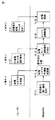
図4は、室内のタッチパネルディスプレイ120を用いて給電モードを選択する場合のユーザの動作と車両ECU140の動作とを説明するための図である。エンジン10は、たとえば、停止状態である場合を想定する。
FIG. 4 is a diagram for explaining the user's operation and the operation of the
図4の(a−1)に示すように、ユーザは、車両1のバッテリ80の電力および/または発電装置である第1MG20によって発生する発電電力を用いて住宅200に対して給電を行なう場合には、車両1の室外(車外)で給電コネクタ610を車両1のDCアウトレット110に取り付ける。
As shown to (a-1) of FIG. 4, when a user supplies electric power with respect to the
図4の(b−1)に示すように、車両ECU140は、給電コネクタ610が接続されたことを認識すると、車両1の室内のタッチパネルディスプレイ120に選択画面を表示し、給電モードの選択操作を受け付け可能な状態(操作受付可能状態)になる。
As shown in (b-1) of FIG. 4, when the
図4の(a−2)に示すように、たとえば、ユーザが、車両1の室内に移動してタッチパネルディスプレイ120を操作して、HV給電モードを選択する操作を行なった場合を想定する。このとき、図4の(b−2)に示すように、車両ECU140は、ユーザの選択操作を受付けてHV給電モードを選択する。そのため、車両ECU140は、図4の(b−3)に示すようにエンジン10を始動させるエンジン始動制御を実行する。
As shown in (a-2) of FIG. 4, for example, it is assumed that the user moves into the
図4の(a−3)に示すように、ユーザが再び車両1の室外に移動して給電装置500の給電開始スイッチ542を操作することによって図4の(b−4)に示すようにHV給電モードで給電が開始される。
As shown in (a-3) of FIG. 4, when the user again moves out of the
このように、ユーザがタッチパネルディスプレイ120を操作して給電を開始する場合には、ユーザは車両1の室内と室外を出入りすることになり、利便性の高い給電を実施できない場合がある。
Thus, when the user operates the
さらに、エンジン10を動作させるHV給電モードをユーザが選択する場合、ユーザは、車両1の近辺の状況がエンジン10の始動を許可してもよい状況であるか否かを確認できる場所にいることが望ましい。
Further, when the user selects the HV power supply mode for operating the
しかしながら、給電に関する各種操作について、ユーザが車両の近辺の状況を確認できる場所にいることを必要とすると、ユーザは、たとえば、携帯端末300を用いて遠隔地から給電状況を確認する等の操作を行なうことができず、利便性の高い給電を実施できない場合がある。
However, if the user needs to be in a place where the situation in the vicinity of the vehicle can be confirmed for various operations related to the power supply, the user performs an operation such as confirming the power supply status from a remote place using the
そこで、本実施の形態においては、給電システム2は、携帯端末300と車両1との間で第1通信方式の通信が確立している場合に、携帯端末300への操作によるHV給電モードの選択が可能な状態になり、携帯端末300と車両1との間で第1通信方式の通信が確立していない場合に、携帯端末300への操作によるHV給電モードの選択が不可能な状態になるように構成された給電モード制御部を備えるものとする。
Therefore, in the present embodiment, the
このようにすると、ユーザは、第1通信方式の通信が確立している場合には、車両1から第1通信方式の通信が可能な距離の範囲内において携帯端末300を用いることで車外からでもHV給電モードの選択を行なうことができる。そのため、利便性の高い給電を実施することができる。また、中継点を経由せずに通信を確立できる距離は車両1に近い距離であるため、ユーザは車両1の近辺を確認できる状況にてHV給電モードを選択することができる。さらに、第1通信方式の通信が確立していない場合は、ユーザが遠隔地にいる可能性がある。そのため、このような場合に、携帯端末300への操作によるHV給電モードの選択が不可能な状態にすることによって、遠隔地からHV給電モードが選択されることを抑制することができる。
In this way, when the communication of the first communication method is established, the user can use the
本実施の形態においては、「給電モード制御部」が携帯端末300の制御部302によって実現される場合を一例として説明する。
In the present embodiment, a case where the “power supply mode control unit” is realized by the
以下、図5を用いて携帯端末300の制御部302で実行される制御処理について説明する。図5は、携帯端末300の制御部302で実行される制御処理を示すフローチャートである。このフローチャートに示される処理は、所定の制御周期(=単位時間)毎に制御部302で実行されるメインルーチン(図示せず)から呼び出されて実行される。
Hereinafter, a control process executed by the
図5に示すように、ステップ(以下、ステップを「S」と記載する)10にて、制御部302は、給電に関する操作を行なうためのアプリケーション(以下、単にアプリと記載する)を起動する操作が行なわれたか否かを判定する。制御部302は、たとえば、ディスプレイ306に表示される、アプリを起動するためのアイコン等を選択するための操作が操作装置308に対して行なわれた場合には、アプリを起動する操作が行なわれたと判定する。アプリを起動する操作が行なわれたと判定される場合(S10にてYES)、処理はS20に移される。
As shown in FIG. 5, in step (hereinafter, “step” is described as “S”) 10,
S20にて、制御部302は、車両1との間で第1通信方式の通信が確立しているか否かを判定する。制御部302は、たとえば、車両1との間で第1通信方式の通信が確立されたときに第1フラグをオン状態にし、車両1との間の第1通信方式の通信が解除されたときに第1フラグをオフ状態にする。制御部302は、第1フラグの状態に基づいて車両1との間で第1通信方式の通信が確立しているか否かを判定してもよい。車両1との間で第1通信方式の通信が確立していると判定される場合(S20にてYES)、処理はS30に移される。
In S20,
S30にて、制御部302は、EV給電モードおよびHV給電モードのいずれも選択を許可する。制御部302は、たとえば、EV給電モードの選択許可フラグと、HV給電モードの選択許可フラグとをいずれもオン状態にする。
In S30,
S40にて、制御部302は、車両1との間で(具体的には、第2通信部134と第4通信部312との間で)第2通信方式の通信が確立しているか否かを判定する。制御部302は、たとえば、車両1との間で第2通信方式の通信が確立されたときに第2フラグをオン状態にし、車両1との間の第2通信方式の通信が解除されたときに第2フラグをオフ状態にする。制御部302は、第2フラグの状態に基づいて車両1との間で第2通信方式の通信が確立しているか否かを判定してもよい。車両1との間で第2通信方式の通信が確立していると判定される場合(S40にてYES)、処理はS50に移される。
In S40,
S50にて、制御部302は、EV給電モードの選択を許可し、HV給電モードの選択を不許可とする。制御部302は、たとえば、EV給電モードの選択許可フラグをオン状態にし、HV給電モードの選択許可フラグをオフ状態にする。
In S50,
S60にて、制御部302は、EV給電モードおよびHV給電モードのいずれも選択を不許可とする。制御部302は、たとえば、EV給電モードの選択許可フラグと、HV給電モードの選択許可フラグをいずれもオフ状態にする。
In S60,
S70にて、制御部302は、選択画面の表示処理を実行する。制御部302は、たとえば、図1のタッチパネルディスプレイ120において表示された給電モードの選択画面と同様の表示構成の選択画面をディスプレイ306に表示する。
In S70,
この場合において、制御部302は、HV給電モードの選択許可フラグがオン状態である場合には、操作装置308への操作によるHV給電モードの選択が可能な状態になるようにする。一方、制御部302は、HV給電モードの選択許可フラグがオフ状態である場合には、操作装置308への操作によるHV給電モードの選択が不可能な状態になるようにする。
In this case, when the selection permission flag for the HV power supply mode is in the on state, the
制御部302は、たとえば、HV給電モードの選択許可フラグがオン状態である場合に、「HV給電モード」の文字列が表示された矩形領域を表示し、選択操作を受け付け可能とすることによってHV給電モードの選択が可能な状態にしてもよい。
For example, when the selection permission flag of the HV power supply mode is on, the
また、制御部302は、たとえば、HV給電モードの選択許可フラグがオフ状態である場合に、当該矩形領域を非表示とすることによってHV給電モードの選択が不可能な状態にしてもよい。あるいは、制御部302は、たとえば、HV給電モードの選択許可フラグがオフ状態である場合に、当該矩形領域の表示態様をHV給電モードの選択許可フラグがオン状態である場合と異なる表示態様(たとえば、グレーアウトさせる等)とし、選択操作を行なわれても受け付けないことによってHV給電モードの選択が不可能な状態にしてもよい。
In addition, for example, when the selection permission flag for the HV power supply mode is in an off state, the
同様に、制御部302は、EV給電モードの選択許可フラグがオン状態である場合には、操作装置308への操作によるEV給電モードの選択が可能な状態になるようにする。一方、制御部302は、EV給電モードの選択許可フラグがオフ状態である場合には、操作装置308への操作によるEV給電モードの選択が不可能な状態になるようにする。なお、EV給電モードの選択が可能な状態にする動作およびEV給電モードの選択が不可能な状態にする動作については、上述のHV給電モードの場合と同様であるため、その詳細な説明は繰り返さない。
Similarly, when the EV power supply mode selection permission flag is on, the
なお、携帯端末300と無線通信装置130との間で第1通信方式の通信と第2通信方式の通信との両方が確立している場合は、少なくとも第1通信方式の通信が確立しているため(S20にてYES)、携帯端末300を用いたHV給電モードの選択は可能となる。
Note that when both the communication of the first communication method and the communication of the second communication method are established between the
以下、図6を用いて車両ECU140で実行される制御処理について説明する。図6は、本実施の形態に係る車両1に搭載された車両ECU140で実行される、給電モードを選択する制御処理を示すフローチャートである。このフローチャートに示される処理は、所定の制御周期(=単位時間)毎に車両ECU140で実行されるメインルーチン(図示せず)から呼び出されて実行される。
Hereinafter, a control process executed by the
図6に示すように、S100にて、車両ECU140は、DCアウトレット110に給電コネクタ610が接続されたか否かを判定する。たとえば、DCアウトレット110に給電コネクタ610の接続を検出するセンサあるいは検出回路を設け、車両ECU140は、これらのセンサあるいは検出回路から送信される信号に基づいて給電コネクタ610がDCアウトレット110に接続されたか否かを判定してもよい。給電コネクタ610の接続を検出するセンサあるいは検出回路は、たとえば、DCアウトレット110への給電コネクタ610の接続に連動してオン状態になるスイッチであってもよいし、取り付けられることによって回路抵抗の変化による電圧変化を検出する電圧センサであってもよい。DCアウトレット110に給電コネクタ610が接続されたと判定される場合(S100にてYES)、処理はS102に移される。
As shown in FIG. 6, in S <b> 100,
S102にて、車両ECU140は、給電モードの選択操作があるか否かを判定する。車両ECU140は、たとえば、タッチパネルディスプレイ120に表示されたいずれかの給電モードの文字列が表示された矩形領域に対してタッチ操作が行なわれた場合に給電モードの選択操作があると判定する。あるいは、車両ECU140は、携帯端末300から無線通信装置130を経由して受信した情報に基づいて給電モードの選択操作があると判定する。
In S102,
たとえば、携帯端末300においてEV給電モードとHV給電モードとのうちのいずれかの給電モードを選択する操作が受け付けられた場合、携帯端末300は、選択された給電モードを特定可能な情報を、無線通信装置130を経由して車両ECU140に送信する。車両ECU140は、当該情報を受信した場合に給電モードの選択操作があると判定する。給電モードの選択操作があると判定される場合(S102にてYES)、処理はS106に移される。
For example, when an operation for selecting one of the EV power supply mode and the HV power supply mode is received in the
S106にて、車両ECU140は、HV給電モードが選択されたか否かを判定する。HV給電モードが選択されたと判定される場合(S106にてYES)、処理はS108に移される。
In S106,
S108にて、車両ECU140は、HV給電モードで車両1の制御を開始する。具体的には、車両ECU140は、エンジン始動制御を実行する等してエンジン10を作動状態にする。
In S108,
一方、HV給電モードが選択されていないと判定される場合(すなわち、EV給電モードが選択されたと判定される場合)(S106にてNO)、処理はS110に移される。 On the other hand, when it is determined that the HV power supply mode is not selected (that is, when it is determined that the EV power supply mode is selected) (NO in S106), the process proceeds to S110.
S110にて、車両ECU140は、EV給電モードで車両1の制御を開始する。具体的には、車両ECU140は、エンジン10を停止状態にする。
In S110,
また、S100にて、給電コネクタが接続されていないと判定される場合(S100にてNO)、あるいは、S102にて、車両ECU140は、給電モードの選択操作が行なわれていないと判定される場合には(S102にてNO)、この処理は終了する。
Further, when it is determined in S100 that the power supply connector is not connected (NO in S100), or in S102,
次に、給電が開始された後の携帯端末300を用いた給電に関する操作の一例について図7を参照しつつ説明する。図7は、本実施の形態に係る車両1に搭載された車両ECU140で実行される、給電開始後の制御処理を示すフローチャートである。このフローチャートに示される処理は、所定の制御周期(=単位時間)毎に繰り返し実行される。
Next, an example of an operation related to power feeding using the
図7に示すように、S200にて、車両ECU140は、給電が開始された後であるか否かを判定する。車両ECU140は、たとえば、給電コネクタ610が接続された状態であって、かつ、電流センサ150によって検出される給電電流が給電しきい値よりも大きい場合に、給電が開始された後であると判定してもよい。給電が開始された後であると判定される場合(S200にてYES)、処理はS208に移される。
As shown in FIG. 7, in S <b> 200,
S208にて、車両ECU140は、バッテリ80のSOC情報を通知する通知しきい値の変更要求があるか否かを判定する。
In S208,
アプリの起動中において、携帯端末300のディスプレイ306には、給電が開始されると、給電に関する予め定められた動作を行なうための設定画面が表示される。予め定められた動作は、たとえば、バッテリ80のSOCに関する情報(以下、SOC情報と記載する)を通知するための、蓄電装置のSOCの第1しきい値を変更する動作と、SOCの通知を要求する動作と、給電を停止する動作とのうちの少なくともいずれかを含む。設定画面には、たとえば、SOC情報を通知するSOCの通知しきい値を変更要求、SOC情報の通知要求および給電の停止要求を行なうことが可能なメニューが表示される。ユーザの操作装置308に対する操作によって各種要求が選択されると、選択された要求を示す情報が無線通信装置130に送信される。
During the activation of the application, when power supply is started, a setting screen for performing a predetermined operation related to power supply is displayed on the
車両ECU140は、たとえば、携帯端末300から変更要求を示す情報を受信する場合に通知しきい値の変更要求があると判定する。あるいは、車両ECU140は、タッチパネルディスプレイ120に対する通知しきい値の変更操作を受け付けた場合に通知しきい値の変更要求があると判定してもよい。通知しきい値の変更要求があると判定される場合(S208にてYES)、処理はS210に移される。
For example, when receiving information indicating a change request from
S210にて、車両ECU140は、通知しきい値を更新する。車両ECU140は、たとえば、新たな通知しきい値としてユーザによって携帯端末300に入力された値を携帯端末300から取得して、取得された値を新たな通知しきい値として更新してもよい。あるいは、ユーザによって携帯端末300に入力された通知しきい値を減少する指示にしたがって現在値から予め定められた値を減算した値を新たな通知しきい値として更新してもよい。あるいは、ユーザからの通知しきい値を増加する指示にしたがって現在値に予め定められた値を加算した値を新たな通知しきい値として更新してもよい。
In S210,
S212にて、車両ECU140は、SOC情報の通知要求があるか否かを判定する。車両ECU140は、たとえば、携帯端末300から通知要求を示す情報を受信する場合、SOC情報の通知要求があると判定する。あるいは、車両ECU140は、タッチパネルディスプレイ120においてSOC情報の通知要求を示す所定の操作を受け付けた場合にSOC情報の通知要求があると判定してもよい。SOC情報の通知要求があると判定される場合(S212にてYES)、処理はS214に移される。
In S212,
S214にて、車両ECU140は、SOC情報の通知処理を行なう。SOC情報は、バッテリ80のSOCの現在値を含む。車両ECU140は、たとえば、バッテリ80の電流、電圧および温度に基づいてバッテリ80のSOCの推定値を現在値として算出する。なお、SOCの推定は周知の方法(たとえば、OCV(Open Circuit Voltage)推定法や電流積算法等)を用いればよくその詳細な説明は行なわない。車両ECU140は、たとえば、SOCの現在値を所定の時間間隔毎に算出する。
In S214,
車両ECU140は、たとえば、携帯端末300に対してSOC情報を送信するとともに、タッチパネルディスプレイ120にSOC情報を表示する。携帯端末300は、受信したSOC情報をディスプレイ306等の表示装置に表示することによってSOC情報をユーザに通知する。なお、車両ECU140は、携帯端末300から通知要求を受けた場合には、携帯端末300に対してSOC情報を送信して、携帯端末300においてのみSOC情報を表示するようにしてもよい。また、表示するSOC情報としては、バッテリ80のSOCの現在値に限定されるものではなく、たとえば、現在の通知しきい値を含むようにしてもよいし、SOCの上限値や下限値を含むようにしてもよいし、あるいは、上限値との差分や下限値との差分を含むようにしてもよい。また、通知方法としては、音声によるものであってもよい。
For example,
SOC情報の通知要求がないと判定される場合(S212にてNO)、処理はS216に移される。S216にて、車両ECU140は、バッテリ80のSOCが通知しきい値よりも大きいか否かを判定する。バッテリ80のSOCが通知しきい値よりも大きいと判定される場合(S216にてYES)、処理はS218に移される。一方、バッテリ80のSOCが通知しきい値以下であると判定される場合(S216にてNO)、処理はS214に移されて、SOC情報が通知される。
If it is determined that there is no SOC information notification request (NO in S212), the process proceeds to S216. In S216,
S218にて、車両ECU140は、給電停止要求があるか否かを判定する。たとえば、ユーザが携帯端末300に対して給電停止要求の操作(たとえば、画面上の所定のボタン画像に対して行なうタッチ操作等)を行なうと携帯端末300は給電停止要求があったことを示す情報を車両ECU140に送信する。車両ECU140は、携帯端末300から給電停止要求があったことを示す情報を受信する場合、給電停止要求があると判定する。あるいは、車両ECU140は、タッチパネルディスプレイ120を用いた給電停止操作を受け付けた場合に給電停止要求があると判定する。給電停止要求があると判定される場合(S218にてYES)、処理はS220に移される。S220にて、車両ECU140は、給電停止処理を実行する。具体的には、車両ECU140は、たとえば、SMR90および給電リレー100を遮断状態にする制御処理を給電停止処理として実行する。なお、給電停止要求がないと判定される場合(S218にてNO)、車両ECU140は、この処理を終了する。
In S218,
以上のような構造およびフローチャートに基づく本実施の形態に係る車両1の動作について図8〜図10を参照しつつ説明する。
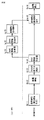
The operation of the
<携帯端末300を用いた給電モードの選択動作について>
図8は、携帯端末300を用いて給電モードを選択する場合のユーザの動作と車両ECU140の動作とを説明するための図である。
<About the operation of selecting a power supply mode using the
FIG. 8 is a diagram for explaining the user's operation and the operation of the
携帯端末300を携帯したユーザが車両1に近づくことによって携帯端末300と第1通信部132との距離が、第1通信方式の通信の確立が可能な範囲内になると、図8の(d−1)に示すように、携帯端末300と第1通信部132との間で第1通信方式の通信が自動的に確立される。
When the user carrying the
図8の(c−1)に示すように、車両1のバッテリ80の電力を用いて住宅200に対して給電を行なう場合、ユーザは車両1の室外で給電コネクタ610を車両1のDCアウトレット110に取り付ける。
As shown in FIG. 8C-1, when power is supplied to the
図8の(d−2)に示すように、車両ECU140は、給電コネクタ610が接続されたことを認識すると(S100にてYES)、給電モードの選択操作を受け付け可能な状態になる(S102)。
As shown in (d-2) of FIG. 8, when
ユーザが携帯端末300においてアプリの起動操作を行なうと(S10にてYES)、車両1と第1通信方式の通信が確立されているため(S20にてYES)、EV給電モードおよびHV給電モードの両方の選択許可フラグがオンされる。そのため、EV給電モードおよびHV給電モードの両方の選択が可能な状態で給電モードの選択画面が表示される(S70)。
When the user performs an application activation operation on portable terminal 300 (YES in S10), communication in
図8の(c−2)に示すように、ユーザが携帯端末300を操作することによってHV給電モードの選択操作が行なわれると、選択された給電モードの情報が第1通信部132に送信される。車両ECU140は、給電モードの情報を受信することによって給電モードの選択操作が行なわれたと判定する(S102にてYES)。そして、図8の(d−3)に示すように、受信した給電モードの情報に基づいてHV給電モードの選択操作が受け付けられる(S106にてYES)。そのため、HV給電モードで車両1の制御が開始される(S108)。すなわち、車両ECU140は、図8の(d−4)に示すようにエンジン始動制御を実行する。
As illustrated in (c-2) of FIG. 8, when the user performs an operation for selecting the HV power supply mode by operating the
図8の(c−3)に示すように、ユーザが車外で給電装置500の給電開始スイッチ542を操作することによって図8の(d−5)に示すように給電が開始される。
As shown in (c-3) of FIG. 8, when the user operates the power
このように、携帯端末300を用いて給電に関する操作を行なうことによって、ユーザは、給電コネクタ610を車両1のDCアウトレット110に取り付ける操作を開始してから車両1の室内に入ることなく給電を開始することができる。
As described above, by performing an operation related to power supply using the
なお、ユーザが携帯端末300においてアプリの起動操作を行なったときに(S10にてYES)、第1通信方式の通信が成立していない場合(S20にてNO)、少なくともHV給電モードの選択が不許可になるため(S50またはS60)、HV給電モードの選択が不可能な状態で給電モードの選択画面が表示される(S70)。 When the user performs an activation operation on the mobile terminal 300 (YES in S10), if communication of the first communication method is not established (NO in S20), at least the HV power supply mode is selected. Since it is not permitted (S50 or S60), the power supply mode selection screen is displayed in a state where selection of the HV power supply mode is impossible (S70).
<携帯端末300を用いて給電状態を示す情報を通知する動作について>
次に、給電が開始された後に携帯端末300を用いて給電状態を示す情報を通知する動作について図9を参照しつつ説明する。図9は、給電が開始された後に携帯端末300からの要求に応じてSOCの情報を通知する場合のユーザの動作と車両ECU140の動作とを説明するための図である。
<About an operation of notifying information indicating a power supply state using the
Next, an operation for notifying information indicating a power supply state using the
携帯端末300を携帯したユーザが住宅200内に移動あるいは住宅200に近づくことによって携帯端末300とアクセスポイント204との間で通信が可能な距離になると、この両者間の通信が自動的に確立される。
When the user carrying the
さらに、第2通信部134とアクセスポイント204との距離が、第2通信方式の通信の確立が可能な範囲内になると、この両者間の通信が自動的に確立される。これにより、図9(f−1)に示すように、第2通信部134とアクセスポイント204との間で第2通信方式の通信が確立される。
Furthermore, when the distance between the second communication unit 134 and the
たとえば、図9の(f−2)に示すように、給電が開始された後においては(S200にてYES)、通知しきい値の変更要求があるか否か(S208)、SOC情報の通知要求があるか否か(S212)、SOCが通知しきい値よりも大きいか否か(S216)、および、給電停止要求があるか否か(S218)が順次判定される。 For example, as shown in (f-2) of FIG. 9, after power feeding is started (YES in S200), whether there is a request for changing a notification threshold (S208), notification of SOC information It is sequentially determined whether or not there is a request (S212), whether or not the SOC is larger than the notification threshold (S216), and whether or not there is a power supply stop request (S218).
図9の(e−1)に示すように、ユーザが携帯端末300に対してバッテリ80のSOC情報の通知を要求する操作を行なった場合、車両ECU140は、SOC情報の通知要求があると判定する(S212にてYES)。図9の(f−3)に示すように、車両ECU140は、SOC情報の通知要求を受け付けるとバッテリ80のSOCの現在値を取得する。そして、図9の(f−4)に示すように、車両ECU140は、取得されたSOCの現在値を含むSOC情報を携帯端末300に送信する(S214)。
As shown in (e-1) of FIG. 9, when the user performs an operation for requesting notification of SOC information of
携帯端末300は、図9の(e−2)に示すように無線通信装置130からSOC情報を受信し、図9の(e−3)に示すように、携帯端末300のディスプレイ306に受信したSOC情報を表示する。
The
一方、車両ECU140は、給電停止要求がない場合には(S218にてNO)、図9の(f−5)に示すように給電を継続する。
On the other hand, when there is no power supply stop request (NO in S218),
<携帯端末300を用いて給電を停止する動作について>
次に、給電が開始された後に携帯端末300を用いて給電を停止する動作について図10を参照しつつ説明する。図10は、給電が開始された後に携帯端末300からの要求に応じて給電を停止する場合のユーザの動作と車両ECU140の動作とを説明するための図である。
<Operation for stopping power supply using
Next, an operation of stopping power supply using the
たとえば、図9の(f−1)と同様に、図10の(h−1)に示すように、第2通信方式の通信が確立される場合を想定する。 For example, as in (f-1) in FIG. 9, it is assumed that communication of the second communication method is established as illustrated in (h-1) in FIG. 10.
たとえば、図10の(h−2)に示すように、給電が開始された後においては(S200にてYES)、上述したとおり、通知しきい値の変更要求があるか否か(S208)、SOC情報の通知要求があるか否か(S212)、SOCが通知しきい値よりも大きいか否か(S216)、および、給電停止要求があるか否か(S218)が順次判定される。 For example, as shown in (h-2) of FIG. 10, after feeding is started (YES in S200), as described above, whether or not there is a request for changing the notification threshold (S208), It is sequentially determined whether or not there is a request for notification of SOC information (S212), whether or not the SOC is larger than the notification threshold (S216), and whether or not there is a request to stop power supply (S218).
車両ECU140は、上述したとおり、所定の時間間隔毎にバッテリ80のSOCの現在値を算出している。図10の(h−3)に示すように算出されたバッテリ80のSOCの現在値が通知しきい値よりも低下した場合には(S216にてNO)、図10の(h−4)に示すように、車両ECU140は、算出されたSOC情報を携帯端末300に送信する(S214)。
As described above,
携帯端末300は、図10の(g−1)に示すように無線通信装置130からSOC情報を受信した場合に、図10の(g−2)に示すように、携帯端末300のディスプレイ306に受信したSOC情報を表示する。
When the
図10の(g−3)に示すように、ユーザは表示されたSOC情報に基づいて携帯端末300に対して給電停止要求操作を行なうと、図10の(h−5)に示すように、車両ECU140は、給電停止要求を受け付ける(S218にてYES)。そのため、車両ECU140は、給電停止処理を実行する(S220)。すなわち、車両ECU140は、給電リレー100やSMR90が遮断状態になるように制御することによって、図10の(h−6)に示すように給電を停止する。
As shown in (g-3) of FIG. 10, when the user performs a power supply stop request operation on the
以上のようにして、本実施の形態に係る給電システム2によると、ユーザは、第1通信方式の通信が確立している場合には、車両1から第1通信方式の無線通信が可能な距離の範囲内において携帯端末300を用いることで車外からでもHV給電モードおよびEV給電モードの選択を行なうことができる。そのため、利便性の高い給電を行なうことができる。また、中継点を経由せずに通信を確立できる距離は車両1に近い距離であるため、ユーザは車両1の近辺を確認できる状況にてHV給電モードを選択することができる。さらに、第1通信方式の通信が確立していない場合は、ユーザが遠隔地にいる可能性がある。そのため、このような場合に、携帯端末300への操作によるHV給電モードの選択が不可能な状態にすることによって、遠隔地からHV給電モードが選択されることを抑制することができる。したがって、エンジンを動作させて給電する給電モードを有する給電システムにおいて利便性の高い給電を実施できる給電システムおよび車両を提供することができる。
As described above, according to the
さらに、携帯端末300と車両1との間で第1通信方式の通信が確立している場合、および/または、携帯端末300と車両1との間で第2通信方式の通信が確立している場合、携帯端末300は、EV給電モードの選択が可能な状態になる。そのため、携帯端末300を用いることで車外からでもEV給電モードの選択を行なうことができる。特に、第2通信方式の通信が確立している場合は、第1通信方式の通信が確立している場合よりも遠距離の通信が可能であるため、遠隔地からEV給電モードの選択が可能となる。そのため、利便性の高い給電を行なうことができる。
Further, when the communication of the first communication method is established between the
さらに、携帯端末300と車両1との間で第1通信方式の通信が確立していない場合、携帯端末300の選択画面によるHV給電モードの選択が不可能な状態になるため、携帯端末300においてHV給電モードを選択できないようにすることができる。
Furthermore, when the communication of the first communication method is not established between the
さらに、住宅200への給電が開始され、かつ、第1通信方式および前記第2通信方式のうちのいずれかの通信方式の通信が確立している場合には、携帯端末300への操作による、給電に関する予め定められた動作が可能な状態になる。そのため、中継点を経由する第2通信方式の通信によって遠隔地からでも給電に関する予め定められた動作を行なうことができるため、利便性の高い給電を実施することができる。
Furthermore, when power supply to the
以下、変形例について記載する。
上述の実施の形態では、第1通信方式の通信としては、Blutoothを利用した通信を一例をとして説明したが、第1通信方式の通信としては、上述したとおり中継点を経由せずにデータの送受信ができればよく、Bluetoothの利用に限定されるものではない。第1通信方式の通信は、たとえば、Wi−fi direct(登録商標)や赤外線を利用した通信であってもよい。
Hereinafter, modifications will be described.
In the above-described embodiment, the communication using the Bluetooth has been described as an example of the communication of the first communication method. However, as described above, the communication of the first communication method can be performed without passing through a relay point. It is only necessary to be able to transmit and receive, and is not limited to the use of Bluetooth. The communication of the first communication method may be, for example, communication using Wi-fi direct (registered trademark) or infrared rays.
上述の実施の形態では、第1通信方式の通信の確立、および、第2通信方式の通信の確立が自動的に行なわれるものとして説明したが、ユーザによる手動操作により確立されてもよい。 In the above-described embodiment, the establishment of communication of the first communication method and the establishment of communication of the second communication method are described as being performed automatically, but they may be established by a manual operation by the user.
上述の実施の形態では、携帯端末300と車両1との間で第1通信方式の通信が確立していない場合でも、第2通信方式の通信が確立している場合には、携帯端末300を用いてEV給電モードを選択することが可能であるものとして説明したが、特にこのような動作に限定されるものではない。たとえば、携帯端末300と車両1との間で第1通信方式の通信が確立していない場合には、HV給電モードおよびEV給電モードのいずれの選択も不可能な状態になるように構成されてもよい。
In the above-described embodiment, even when communication of the first communication method is not established between the
さらに、上述の実施の形態においては、HV給電モードは、エンジン10を常時作動状態にする給電モードであるものとして説明したが、エンジン10の作動を許容した状態でエンジンを用いた発電電力およびバッテリ80の電力のうちの少なくともいずれかを車両1の外部の電気負荷に供給する電力供給態様であれば、特にエンジン10を常時作動状態にする電力供給態様に限定されるものではない。
Furthermore, in the above-described embodiment, the HV power supply mode has been described as a power supply mode in which the
たとえば、HV給電モードは、バッテリ80のSOCがしきい値になるまでは、バッテリ80の電力を外部の電気負荷に供給し、バッテリ80のSOCがしきい値よりも低下したときにエンジン10を作動状態にして、エンジン10用いて発電される電力を外部の電気負荷に供給するものであってもよい。
For example, in the HV power supply mode, the electric power of the
さらに、上述の実施の形態においては、バッテリ80のSOCが第1しきい値以下になるとSOC情報を携帯端末300に送信することによってSOC情報をユーザに通知するものとして説明したが、たとえば、燃料残量センサ170によって検出されるエンジン10の燃料の残量が第2しきい値以下になると燃料の残量に関する情報を携帯端末300に送信してもよい。燃料の残量に関する情報は、燃料の残量、残量の下限値、残量と下限値との差に基づくHV給電モードでの給電可能時間等を含むようにしてもよい。また、第2しきい値は、携帯端末300の操作によって変更可能としてもよい。
Furthermore, in the above-described embodiment, it has been described that the SOC information is notified to the user by transmitting the SOC information to the
さらに、上述の実施の形態においては、第1通信方式の通信が可能な距離の範囲内において携帯端末300を用いたHV給電モードの選択を可能とするものとして説明したが、車両ECU140は、たとえば、車両1のシステム停止時等の走行不可状態において、無線通信装置130が出力する電波の強度を弱めるなどの調整を行ない、第1通信方式の通信が可能な距離の範囲を車両1の近辺の状況が確認可能な範囲(たとえば、車両1を視認可能な範囲あるいは車両1の近辺に短時間で移動可能な範囲)に設定しておくようにしてもよい。このようにすると、消費電力の増加を抑制しつつ、ユーザが携帯端末300を用いてHV給電モードの選択を車両1に要求する場合、ユーザは車両1の近辺の状況が確認可能な範囲内に移動することになる。そのため、ユーザに車両1の近辺の状況を確認させることができる。
Furthermore, in the above-described embodiment, it has been described that the HV power supply mode using the
さらに、車両ECU140は、バッテリ80のSOCが下限値になる場合、あるいは、燃料の残量が下限値になる場合にSMR90や給電リレー100を遮断することによって給電を停止してもよい。この場合、たとえば、ユーザのタッチパネルディスプレイ120の操作あるいは携帯端末300の操作によりバッテリ80の下限値を変更可能としてもよい。
Further, the
さらに、上述の実施の形態では、携帯端末300の制御部302によって「給電モード制御部」を実現するものとして説明したが、たとえば、車両ECU140によって「給電モード制御部」を実現してもよい。
Furthermore, in the above-described embodiment, the “power supply mode control unit” is realized by the
この場合、車両ECU140は、たとえば、携帯端末300と車両1との間で第1通信方式の通信が確立している場合にのみ、HV給電モードの選択が可能な状態になるように構成される。車両ECU140は、たとえば、携帯端末300からHV給電モードの選択要求があった場合に、携帯端末300と車両1との間で第1通信方式の通信が確立していないときは、HV給電モードの選択を禁止する。
In this case, for example,
このようにすると、利便性の高い給電を行なうことができるとともに、遠隔地からHV給電モードが選択されることを抑制することができる。 If it does in this way, while being able to supply electric power with high convenience, it can control that HV electric supply mode is selected from a remote place.
以下に、図11を用いてこの変形例に係る給電システム2の車両ECUで実行される制御処理の一例を説明する。
Below, an example of the control process performed by vehicle ECU of the electric
なお、図11のフローチャートにおいて、図6のフローチャートと同じ処理については同じステップ番号が付与されている。そのため、その詳細な説明は繰り返さない。 In the flowchart of FIG. 11, the same step number is assigned to the same process as that of the flowchart of FIG. 6. Therefore, detailed description thereof will not be repeated.
S102にて、給電モードの選択操作があると判定される場合(S102にてYES)、S104にて、車両ECU140は、給電モードの選択操作がタッチ操作によるものであるか、あるいは、第1通信方式の通信の確立中における携帯端末300への操作によるものであるか、あるいは、それら操作によるものでないかを判定する。給電モードの選択操作がタッチ操作によるものであると判定される場合、あるいは、第1通信方式の通信の確立中における携帯端末300への操作によるものであると判定される場合、処理はS106に移される。それらの操作によるものでない場合(S104にてNO)、この処理は終了する。
When it is determined in S102 that there is a power feeding mode selection operation (YES in S102), in S104,
このような処理によって、第1通信方式の通信が確立していない場合には(S104)、HV給電モードを選択する処理に移行しないようにすることでHV給電モードの選択が禁止される。そして、第1通信方式の通信が確立している場合にのみHV給電モードを選択処理に移行することが可能となる。 When the communication of the first communication method is not established by such processing (S104), selection of the HV power supply mode is prohibited by not shifting to the processing of selecting the HV power supply mode. The HV power supply mode can be shifted to the selection process only when communication of the first communication method is established.
さらに、上述の実施の形態では、携帯端末300の制御部302によって「給電モード制御部」を実現するものとして説明したが、たとえば、携帯端末300と車両1との間で第2通信方式の通信が確立する場合において、携帯端末300と車両1とで送受信されるデータが通信網400に接続されるサーバ−402を経由する場合には、サーバ402によって「給電モード制御部」が実現されてもよい。たとえば、サーバ402は、携帯端末300と車両1との間で第2通信方式の通信が確立されており、かつ、第1通信方式の通信が確立されていない場合において、携帯端末300からHV給電モードの選択が要求されるときには、車両1に対してHV給電モードの選択要求を行なわないようにしてもよい。なお、この場合において、携帯端末300と車両1との間で第1通信方式の通信が確立された場合には、携帯端末300および車両1の各々あるいは少なくとも一方が携帯端末300と車両1との間で第1通信方式の通信が確立されていることを示す情報をサーバ402に送信するものとする。サーバ402は、当該情報に基づいて携帯端末300と車両1との間で第1通信方式の通信が確立されているか否かを判定する。
Further, in the above-described embodiment, the “power supply mode control unit” is realized by the
なお、上記した変形例は、その全部または一部を適宜組み合わせて実施してもよい。
今回開示された実施の形態はすべての点で例示であって制限的なものではないと考えられるべきである。本開示の範囲は上記した説明ではなくて特許請求の範囲によって示され、特許請求の範囲と均等の意味および範囲内でのすべての変更が含まれることが意図される。
In addition, you may implement the above-mentioned modification combining all or one part suitably.
The embodiment disclosed this time should be considered as illustrative in all points and not restrictive. The scope of the present disclosure is defined by the terms of the claims, rather than the description above, and is intended to include any modifications within the scope and meaning equivalent to the terms of the claims.
1 車両、2 給電システム、10 エンジン、20 第1MG、30 第2MG、40 動力分割装置、50 減速機、60 駆動輪、80 バッテリ、100 給電リレー、101 シート、110 アウトレット、120 タッチパネルディスプレイ、130,304 無線通信装置、132,134,310,312 通信部、140 車両ECU、150 電流センサ、160 電圧センサ、170 燃料残量センサ、200 住宅、202 家電機器、204 アクセスポイント、206 配電盤、208 系統電源、300 携帯端末、302 制御部、306 ディスプレイ、308 操作装置、400 通信網、500 給電装置、510 インバータ、542 給電開始スイッチ、544 給電停止スイッチ、550 給電ECU、600 接続ケーブル、610 給電コネクタ。
DESCRIPTION OF
Claims (9)
前記エンジンの作動を許容した状態で前記発電装置および前記蓄電装置のうちの少なくとも一方の電力を前記電気負荷に供給する第1給電モードと、前記エンジンを停止させた状態で前記蓄電装置の電力を前記電気負荷に供給する第2給電モードとのうちのいずれかの給電モードで給電を行なう、給電システムであって、
前記車両は、中継点を経由せずに携帯端末との間で通信を確立する第1通信方式と、中継点を経由して前記携帯端末との間で通信を確立する第2通信方式と、で無線通信を行なうように構成された無線通信装置を有し、
前記給電システムは、前記携帯端末と前記車両との間で前記第1通信方式の通信が確立している場合に、前記携帯端末への操作による前記第1給電モードの選択が可能な状態になり、前記携帯端末と前記車両との間で前記第1通信方式の通信が確立していない場合に、前記携帯端末への操作による前記第1給電モードの選択が不可能な状態になるように構成された給電モード制御部、を備える、給電システム。 A vehicle having a power generation device that generates power using engine power, a power storage device, and an outlet that can be connected to an electrical load outside the vehicle;
A first power supply mode in which power of at least one of the power generation device and the power storage device is supplied to the electric load in a state in which the operation of the engine is allowed; and power of the power storage device in a state in which the engine is stopped A power feeding system that performs power feeding in any one of the second power feeding modes to be supplied to the electric load,
The vehicle has a first communication method for establishing communication with a mobile terminal without going through a relay point, and a second communication method for establishing communication with the mobile terminal through a relay point; A wireless communication device configured to perform wireless communication with
When the communication of the first communication method is established between the mobile terminal and the vehicle, the power supply system is in a state in which the first power supply mode can be selected by an operation on the mobile terminal. When the communication of the first communication method is not established between the mobile terminal and the vehicle, the first power supply mode cannot be selected by operating the mobile terminal. A power feeding system comprising a power feeding mode control unit.
前記給電モード制御部は、前記携帯端末と前記車両との間で前記第1通信方式の通信が確立していない場合、前記携帯端末の前記選択画面による前記第1給電モードの選択が不可能な状態になるように構成される、請求項1〜4のいずれかに記載の給電システム。 The mobile terminal is configured such that a power supply mode selection screen is displayed on a display device,
The power supply mode control unit is unable to select the first power supply mode on the selection screen of the mobile terminal when communication of the first communication method is not established between the mobile terminal and the vehicle. The electric power feeding system in any one of Claims 1-4 comprised so that it may be in a state.
蓄電装置と、
車両の外部の電気負荷に接続可能なアウトレットと、
中継点を経由せずに携帯端末との間で通信を確立する第1通信方式と、中継点を経由して前記携帯端末との間で通信を確立する第2通信方式と、で無線通信を行なうように構成された無線通信装置と、
前記エンジンの作動を許容した状態で前記発電装置および前記蓄電装置のうちの少なくとも一方の電力を前記電気負荷に供給する第1給電モードと、前記エンジンを停止させた状態で前記蓄電装置の電力を前記電気負荷に供給する第2給電モードとのうちのいずれかの給電モードで給電を行なう、制御部とを備え、
前記制御部は、前記携帯端末と前記車両との間で前記第1通信方式の通信が確立している場合にのみ、前記携帯端末への操作による前記第1給電モードの選択が可能な状態になるように構成される、車両。 A power generation device that generates power using engine power;
A power storage device;
An outlet that can be connected to an electrical load outside the vehicle;
Wireless communication between the first communication method that establishes communication with a mobile terminal without going through a relay point and the second communication method that establishes communication with the mobile terminal through a relay point A wireless communication device configured to perform;
A first power supply mode in which power of at least one of the power generation device and the power storage device is supplied to the electric load in a state in which the operation of the engine is allowed; and power of the power storage device in a state in which the engine is stopped A controller that feeds power in any one of the second power feeding modes to be supplied to the electrical load;
The control unit is in a state in which the first power supply mode can be selected by an operation on the portable terminal only when communication of the first communication method is established between the portable terminal and the vehicle. A vehicle configured to be.
Priority Applications (7)
| Application Number | Priority Date | Filing Date | Title |
|---|---|---|---|
| JP2016222299A JP6477670B2 (en) | 2016-11-15 | 2016-11-15 | Power feeding system and vehicle |
| BR102017023381-2A BR102017023381B1 (en) | 2016-11-15 | 2017-10-30 | POWER SYSTEM AND VEHICLE |
| KR1020170143100A KR101982936B1 (en) | 2016-11-15 | 2017-10-31 | Feed system and vehicle |
| RU2017138095A RU2670277C1 (en) | 2016-11-15 | 2017-11-01 | Electric power supply system and vehicle |
| US15/801,959 US10384555B2 (en) | 2016-11-15 | 2017-11-02 | Feed system and vehicle |
| EP17200131.5A EP3321121B1 (en) | 2016-11-15 | 2017-11-06 | Feed system and vehicle |
| CN201711081969.6A CN108075553B (en) | 2016-11-15 | 2017-11-07 | Power supply system and vehicle |
Applications Claiming Priority (1)
| Application Number | Priority Date | Filing Date | Title |
|---|---|---|---|
| JP2016222299A JP6477670B2 (en) | 2016-11-15 | 2016-11-15 | Power feeding system and vehicle |
Publications (2)
| Publication Number | Publication Date |
|---|---|
| JP2018082536A JP2018082536A (en) | 2018-05-24 |
| JP6477670B2 true JP6477670B2 (en) | 2019-03-06 |
Family
ID=60262831
Family Applications (1)
| Application Number | Title | Priority Date | Filing Date |
|---|---|---|---|
| JP2016222299A Active JP6477670B2 (en) | 2016-11-15 | 2016-11-15 | Power feeding system and vehicle |
Country Status (7)
| Country | Link |
|---|---|
| US (1) | US10384555B2 (en) |
| EP (1) | EP3321121B1 (en) |
| JP (1) | JP6477670B2 (en) |
| KR (1) | KR101982936B1 (en) |
| CN (1) | CN108075553B (en) |
| BR (1) | BR102017023381B1 (en) |
| RU (1) | RU2670277C1 (en) |
Families Citing this family (6)
| Publication number | Priority date | Publication date | Assignee | Title |
|---|---|---|---|---|
| US10328940B2 (en) * | 2017-03-16 | 2019-06-25 | Ford Global Technologies, Llc | Secure idle for a vehicle generator |
| WO2019225168A1 (en) * | 2018-05-22 | 2019-11-28 | 本田技研工業株式会社 | Electric-powered vehicle and method for controlling electric-powered vehicle |
| KR20210023056A (en) * | 2019-08-21 | 2021-03-04 | 현대자동차주식회사 | Apparatus for managing power of eleceric vehicle and method thereof |
| JP7380272B2 (en) * | 2020-02-04 | 2023-11-15 | トヨタ自動車株式会社 | vehicle |
| WO2022014655A1 (en) * | 2020-07-14 | 2022-01-20 | 三菱自動車工業株式会社 | Electric vehicle |
| JP2022183655A (en) * | 2021-05-31 | 2022-12-13 | マツダ株式会社 | Control device of electric vehicle |
Family Cites Families (18)
| Publication number | Priority date | Publication date | Assignee | Title |
|---|---|---|---|---|
| US5103923A (en) * | 1989-11-30 | 1992-04-14 | Marathon Letourneau Company | Method and apparatus for propelling and retarding off-road haulers |
| KR100438185B1 (en) * | 1999-12-06 | 2004-07-02 | 주식회사 팬택앤큐리텔 | Remote Controller for Vehicle using Wireless Communication Base Station |
| JP4140552B2 (en) * | 2004-04-28 | 2008-08-27 | トヨタ自動車株式会社 | Automotive power supply device and automobile equipped with the same |
| KR20080003905A (en) * | 2005-05-05 | 2008-01-08 | 에이에프에스 트리니티 파워 코포레이션 | Plug-in hybrid vehicle with fast energy storage |
| US20070282495A1 (en) | 2006-05-11 | 2007-12-06 | University Of Delaware | System and method for assessing vehicle to grid (v2g) integration |
| JP5173276B2 (en) * | 2007-06-22 | 2013-04-03 | パナソニック株式会社 | Power supply system, power supply control method for power supply system, and power supply control program therefor |
| US20100017045A1 (en) * | 2007-11-30 | 2010-01-21 | Johnson Controls Technology Company | Electrical demand response using energy storage in vehicles and buildings |
| CN201252421Y (en) * | 2008-06-19 | 2009-06-03 | 科泰电源设备(上海)有限公司 | Power automatic switching unit for communication base station |
| US8583307B2 (en) * | 2009-06-10 | 2013-11-12 | Toyota Jidosha Kabushiki Kaisha | Power supply system for electrically powered vehicle and method for controlling the same |
| CN101710727B (en) * | 2009-11-05 | 2012-07-04 | 杨益平 | Control method and control system of power supply and electronic equipment of motor vehicle |
| JP5170482B2 (en) * | 2011-08-30 | 2013-03-27 | トヨタ自動車株式会社 | Method for identifying operation mode in charging / power supply system between vehicle and outside, and identification device for identifying operation mode of the system by the identification method |
| EP2830185B1 (en) * | 2012-03-21 | 2019-10-09 | Toyota Jidosha Kabushiki Kaisha | Electric vehicle, electric power facilities and electric power supply system |
| DE112012006852T5 (en) * | 2012-08-31 | 2015-06-03 | Toyota Jidosha Kabushiki Kaisha | Vehicle and control method for the vehicle |
| KR101776709B1 (en) * | 2013-08-13 | 2017-09-08 | 한화지상방산 주식회사 | Method and system for vehicle remote control system using user terminal |
| JP2015122892A (en) * | 2013-12-24 | 2015-07-02 | トヨタ自動車株式会社 | Electric-vehicular power-feeding system |
| JP6338464B2 (en) * | 2014-06-11 | 2018-06-06 | 本田技研工業株式会社 | Control specification changing system and vehicle |
| JP6146384B2 (en) | 2014-08-08 | 2017-06-14 | トヨタ自動車株式会社 | Hybrid vehicle |
| KR102266660B1 (en) * | 2015-01-20 | 2021-06-21 | 인포뱅크 주식회사 | A portable terminal for controlling a car interface and a method for operating it |
-
2016
- 2016-11-15 JP JP2016222299A patent/JP6477670B2/en active Active
-
2017
- 2017-10-30 BR BR102017023381-2A patent/BR102017023381B1/en active IP Right Grant
- 2017-10-31 KR KR1020170143100A patent/KR101982936B1/en active IP Right Grant
- 2017-11-01 RU RU2017138095A patent/RU2670277C1/en active
- 2017-11-02 US US15/801,959 patent/US10384555B2/en not_active Expired - Fee Related
- 2017-11-06 EP EP17200131.5A patent/EP3321121B1/en active Active
- 2017-11-07 CN CN201711081969.6A patent/CN108075553B/en not_active Expired - Fee Related
Also Published As
| Publication number | Publication date |
|---|---|
| CN108075553A (en) | 2018-05-25 |
| US10384555B2 (en) | 2019-08-20 |
| EP3321121A3 (en) | 2018-09-05 |
| RU2670277C1 (en) | 2018-10-22 |
| BR102017023381B1 (en) | 2023-04-04 |
| EP3321121B1 (en) | 2021-07-28 |
| US20180141456A1 (en) | 2018-05-24 |
| EP3321121A2 (en) | 2018-05-16 |
| BR102017023381A2 (en) | 2018-06-26 |
| CN108075553B (en) | 2020-10-13 |
| KR101982936B1 (en) | 2019-05-27 |
| JP2018082536A (en) | 2018-05-24 |
| KR20180054437A (en) | 2018-05-24 |
Similar Documents
| Publication | Publication Date | Title |
|---|---|---|
| JP6477670B2 (en) | Power feeding system and vehicle | |
| US10710467B2 (en) | Information providing system and method, and server used for information providing system and method | |
| US9884618B2 (en) | Vehicle, and control method for vehicle | |
| US10383156B2 (en) | Operating a mobile hotspot at a vehicle | |
| KR101845647B1 (en) | Power management device for vehicle | |
| CN111071080B (en) | Vehicle and charging system | |
| CN107483303A (en) | Household electrical appliances match somebody with somebody network method, mobile terminal and home appliance | |
| JP2021096783A (en) | Program update method | |
| CN104283255A (en) | Add-on communication apparatus attached to cable installment type charging control device | |
| CN109474657B (en) | Wireless service discovery function | |
| US10946760B2 (en) | Remote indicator of state of charging of electric vehicle | |
| KR101657899B1 (en) | Charging system for electric vehicle based on rf energy harvesting and charging method for electric vehicle based on rf energy harvesting | |
| JP5691923B2 (en) | Vehicle and vehicle control method | |
| JP2015109780A (en) | Vehicle power supply system | |
| JP7234979B2 (en) | Information notification device, information notification system, information notification method, and vehicle | |
| WO2011074095A1 (en) | Information transmission device of vehicle and electrically-driven vehicle provided with the same | |
| JP2020104755A (en) | Plug-in hybrid vehicle | |
| JP7070270B2 (en) | Charging system | |
| JP7172742B2 (en) | Display device for charging system and display method for charging system | |
| JP2016049003A (en) | Non-contact charging system and battery-mounted vehicle | |
| JP2022098757A (en) | Power supply control device | |
| JP2014185560A (en) | Vehicle control device | |
| JP2022091473A (en) | Electric vehicle | |
| CN110535246A (en) | A kind of wireless charging method, terminal and vehicle | |
| CN117183805A (en) | Method and device for transmitting vehicle data |
Legal Events
| Date | Code | Title | Description |
|---|---|---|---|
| A621 | Written request for application examination |
Free format text: JAPANESE INTERMEDIATE CODE: A621 Effective date: 20180222 |
|
| A977 | Report on retrieval |
Free format text: JAPANESE INTERMEDIATE CODE: A971007 Effective date: 20181126 |
|
| TRDD | Decision of grant or rejection written | ||
| A01 | Written decision to grant a patent or to grant a registration (utility model) |
Free format text: JAPANESE INTERMEDIATE CODE: A01 Effective date: 20190108 |
|
| A61 | First payment of annual fees (during grant procedure) |
Free format text: JAPANESE INTERMEDIATE CODE: A61 Effective date: 20190121 |
|
| R151 | Written notification of patent or utility model registration |
Ref document number: 6477670 Country of ref document: JP Free format text: JAPANESE INTERMEDIATE CODE: R151 |