JP2012161241A - Power supply system for electric vehicles - Google Patents
Power supply system for electric vehicles Download PDFInfo
- Publication number
- JP2012161241A JP2012161241A JP2012054788A JP2012054788A JP2012161241A JP 2012161241 A JP2012161241 A JP 2012161241A JP 2012054788 A JP2012054788 A JP 2012054788A JP 2012054788 A JP2012054788 A JP 2012054788A JP 2012161241 A JP2012161241 A JP 2012161241A
- Authority
- JP
- Japan
- Prior art keywords
- charging
- power supply
- electric vehicle
- vehicle
- user
- Prior art date
- Legal status (The legal status is an assumption and is not a legal conclusion. Google has not performed a legal analysis and makes no representation as to the accuracy of the status listed.)
- Granted
Links
Images


Classifications
-
- Y—GENERAL TAGGING OF NEW TECHNOLOGICAL DEVELOPMENTS; GENERAL TAGGING OF CROSS-SECTIONAL TECHNOLOGIES SPANNING OVER SEVERAL SECTIONS OF THE IPC; TECHNICAL SUBJECTS COVERED BY FORMER USPC CROSS-REFERENCE ART COLLECTIONS [XRACs] AND DIGESTS
- Y02—TECHNOLOGIES OR APPLICATIONS FOR MITIGATION OR ADAPTATION AGAINST CLIMATE CHANGE
- Y02E—REDUCTION OF GREENHOUSE GAS [GHG] EMISSIONS, RELATED TO ENERGY GENERATION, TRANSMISSION OR DISTRIBUTION
- Y02E60/00—Enabling technologies; Technologies with a potential or indirect contribution to GHG emissions mitigation
- Y02E60/10—Energy storage using batteries
-
- Y—GENERAL TAGGING OF NEW TECHNOLOGICAL DEVELOPMENTS; GENERAL TAGGING OF CROSS-SECTIONAL TECHNOLOGIES SPANNING OVER SEVERAL SECTIONS OF THE IPC; TECHNICAL SUBJECTS COVERED BY FORMER USPC CROSS-REFERENCE ART COLLECTIONS [XRACs] AND DIGESTS
- Y02—TECHNOLOGIES OR APPLICATIONS FOR MITIGATION OR ADAPTATION AGAINST CLIMATE CHANGE
- Y02T—CLIMATE CHANGE MITIGATION TECHNOLOGIES RELATED TO TRANSPORTATION
- Y02T10/00—Road transport of goods or passengers
- Y02T10/60—Other road transportation technologies with climate change mitigation effect
- Y02T10/70—Energy storage systems for electromobility, e.g. batteries
-
- Y—GENERAL TAGGING OF NEW TECHNOLOGICAL DEVELOPMENTS; GENERAL TAGGING OF CROSS-SECTIONAL TECHNOLOGIES SPANNING OVER SEVERAL SECTIONS OF THE IPC; TECHNICAL SUBJECTS COVERED BY FORMER USPC CROSS-REFERENCE ART COLLECTIONS [XRACs] AND DIGESTS
- Y02—TECHNOLOGIES OR APPLICATIONS FOR MITIGATION OR ADAPTATION AGAINST CLIMATE CHANGE
- Y02T—CLIMATE CHANGE MITIGATION TECHNOLOGIES RELATED TO TRANSPORTATION
- Y02T90/00—Enabling technologies or technologies with a potential or indirect contribution to GHG emissions mitigation
- Y02T90/10—Technologies relating to charging of electric vehicles
- Y02T90/16—Information or communication technologies improving the operation of electric vehicles
- Y02T90/167—Systems integrating technologies related to power network operation and communication or information technologies for supporting the interoperability of electric or hybrid vehicles, i.e. smartgrids as interface for battery charging of electric vehicles [EV] or hybrid vehicles [HEV]
-
- Y—GENERAL TAGGING OF NEW TECHNOLOGICAL DEVELOPMENTS; GENERAL TAGGING OF CROSS-SECTIONAL TECHNOLOGIES SPANNING OVER SEVERAL SECTIONS OF THE IPC; TECHNICAL SUBJECTS COVERED BY FORMER USPC CROSS-REFERENCE ART COLLECTIONS [XRACs] AND DIGESTS
- Y04—INFORMATION OR COMMUNICATION TECHNOLOGIES HAVING AN IMPACT ON OTHER TECHNOLOGY AREAS
- Y04S—SYSTEMS INTEGRATING TECHNOLOGIES RELATED TO POWER NETWORK OPERATION, COMMUNICATION OR INFORMATION TECHNOLOGIES FOR IMPROVING THE ELECTRICAL POWER GENERATION, TRANSMISSION, DISTRIBUTION, MANAGEMENT OR USAGE, i.e. SMART GRIDS
- Y04S30/00—Systems supporting specific end-user applications in the sector of transportation
- Y04S30/10—Systems supporting the interoperability of electric or hybrid vehicles
- Y04S30/14—Details associated with the interoperability, e.g. vehicle recognition, authentication, identification or billing
Abstract
Description
本発明は、電気自動車やハイブリッド車などの電動車両に搭載された電池の充電を行うための給電システムに関する。 The present invention relates to a power supply system for charging a battery mounted on an electric vehicle such as an electric vehicle or a hybrid vehicle.
環境負荷の低減を目的として、電気自動車やハイブリッド車などの電動自動車が開発されている。これら電動自動車を広く普及させるには、車載電池を充電するための給電スタンドが各所に整備される必要がある。特に、電動自動車を駐車場に入庫中、車載電池を充電できる給電スタンドが効率的な充電を可能にするものとして期待されている。そのような給電スタンドに関する技術として、特許文献1に記載のものがある。
Electric vehicles such as electric vehicles and hybrid vehicles have been developed for the purpose of reducing environmental burden. In order to widely disseminate these electric vehicles, it is necessary to provide power supply stands for charging on-vehicle batteries in various places. In particular, a power supply stand that can charge an in-vehicle battery while an electric vehicle is in a parking lot is expected to enable efficient charging. There exists a thing of
この技術は、車両を駐車場に入庫させる時に入庫時刻を記録した駐車券を発行し、出庫時にこの駐車券を料金精算機に読み取らせて駐車料金の精算を済ませると、車両の出庫を許可するように構成した駐車場装置に関する。この駐車場内には、電気自動車のバッテリー(車載電池)を充電する充電装置(給電スタンド)と充電情報入出力装置が設けられている。この充電情報入出力装置は、駐車券に対して充電装置によるバッテリーへの充電時間の算定情報を記録することができる充電情報記録手段を具備する。また、料金精算機は、駐車券に記録されている充電情報から充電料金を算出する充電料金算出手段を具備する。そして、この駐車場装置は、駐車料金と充電料金の精算を済ませると、車両の出庫を許可するように構成されている。 This technology issues a parking ticket that records the time of entry when the vehicle enters the parking lot, and allows the vehicle to be issued when the parking fee is settled by reading the parking ticket when leaving the vehicle. It is related with the parking lot apparatus comprised as follows. In this parking lot, a charging device (power supply stand) for charging a battery (vehicle battery) of an electric vehicle and a charging information input / output device are provided. The charging information input / output device includes charging information recording means capable of recording calculation information of charging time of the battery by the charging device with respect to the parking ticket. Further, the fee settlement machine includes a charging fee calculation means for calculating a charging fee from the charging information recorded on the parking ticket. And this parking lot apparatus is comprised so that the vehicle may be left when payment of a parking charge and a charge charge is completed.
上記の給電システムは、車載電池に給電した電力量から充電に要する料金を算出することはできるが、充電がいつ完了するか、或いは電池容量のどの程度の割合まで充電が完了したか、といった充電の進行状態に関する情報をユーザに提供することができない。特に、低速充電を行うための給電システムの場合、通常、充電時間が6〜8時間程度と長いため、充電の進行状態をユーザに提供する必要性が高い。その一方で、車載電池と給電スタンドとを接続する充電ケーブルには、給電路となる電力線が設けられているだけであり、車載電池と給電スタンドとで充電状態に関するデータを授受するための通信線を備えていないため、給電スタンドが車載電池自体の電気量を把握することが困難である。 The above power supply system can calculate the charge required for charging from the amount of power supplied to the in-vehicle battery, but charging such as when charging is completed or to what percentage of the battery capacity is completed. It is not possible to provide information on the progress status of the user. In particular, in the case of a power feeding system for performing low-speed charging, since the charging time is usually as long as about 6 to 8 hours, it is highly necessary to provide the user with the progress of charging. On the other hand, the charging cable that connects the in-vehicle battery and the power supply station is only provided with a power line that serves as a power supply path, and a communication line for exchanging data on the charging state between the in-vehicle battery and the power supply station. Therefore, it is difficult for the power supply stand to grasp the amount of electricity of the in-vehicle battery itself.
本発明は、上記の事情に鑑みてなされたもので、その目的の一つは、ユーザに対して充電終了時刻などの充電の進行状態を予測して知らせることができる電動車両用給電システムを提供することにある。 The present invention has been made in view of the above circumstances, and one of its purposes is to provide a power feeding system for an electric vehicle that can predict and inform the user of the progress of charging, such as the charging end time. There is to do.
また、本発明の他の目的は、電池の取り換え時期など車載電池の劣化状態を予測してユーザに知らせることができる電動車両用給電システムを提供することにある。 Another object of the present invention is to provide a power supply system for an electric vehicle capable of predicting a deterioration state of an in-vehicle battery such as a battery replacement time and informing a user of the deterioration state.
本発明の別の目的は、車載電池の劣化状態を他のユーザの車載電池の劣化状態と対比してユーザに知らせることができる電動車両用給電システムを提供することにある。 Another object of the present invention is to provide a power supply system for an electric vehicle that can inform the user of the deterioration state of the in-vehicle battery in comparison with the deterioration state of the in-vehicle battery of another user.
本発明の電動車両用給電システムは、電動車両の車載電池に給電するための給電スタンドと、この給電スタンドのユーザが利用する端末機と、前記給電スタンド及び端末機の各々と通信網を介して通信するサーバとを備える。前記給電スタンドは、前記端末機からのサーバを介した要求に応じて、車載電池への給電を行うスイッチ手段と、前記車載電池に給電した電力量を計測する電力量計測手段とを有する。前記サーバは、記憶手段と、ユーザ認証手段と、充電進行状態演算手段とを備える。この記憶手段は、前記ユーザとその登録電動車両とを特定するためのユーザマスタ情報とテーブルとを有する。テーブルは、登録電動車両と、その車載電池の充電特性データであって前記電力量計測手段で取得できる物理量の特性データとを関連付ける。ユーザ認証手段は、前記端末機から送信されたユーザ入力情報と前記ユーザマスタ情報とを参照して、ユーザの認証を行う。そして、充電進行状態演算手段は、認証されたユーザの登録電動車両に対応する充電特性データを前記テーブルから抽出し、前記給電スタンドから送信された電力量計測手段の計測データを抽出された充電特性データと参照して車載電池の充電進行状態を演算し、この演算結果を端末機に送信するための充電進行状態データとして生成する。 A power supply system for an electric vehicle according to the present invention includes a power supply stand for supplying power to an on-vehicle battery of the electric vehicle, a terminal used by a user of the power supply stand, and each of the power supply stand and the terminal via a communication network. And a server for communication. The power supply stand includes switch means for supplying power to the in-vehicle battery in response to a request from the terminal via the server, and power amount measuring means for measuring the amount of power supplied to the in-vehicle battery. The server includes a storage unit, a user authentication unit, and a charging progress state calculation unit. The storage means includes user master information and a table for identifying the user and the registered electric vehicle. The table associates the registered electric vehicle with the characteristic data of the physical quantity that can be acquired by the electric energy measuring means, which is the charging characteristic data of the vehicle battery. The user authentication means authenticates the user with reference to the user input information transmitted from the terminal and the user master information. Then, the charging progress state calculation means extracts charging characteristic data corresponding to the registered electric vehicle of the authenticated user from the table, and the charging characteristic obtained by extracting the measurement data of the electric energy measuring means transmitted from the power supply stand The charging progress state of the in-vehicle battery is calculated with reference to the data, and the calculation result is generated as charging progress state data for transmitting to the terminal.
この構成によれば、登録電動車両の車載電池に対応した充電特性データを利用して、その電池の充電進行状態を充電進行状態演算手段により的確に認識することができる。また、その充電特性データは、車載電池の充電特性データであって電力量計測手段で取得できる物理量(例えば充電電力などの電気量)の特性データであるため、給電スタンドと車載電池とを接続する充電ケーブルが、給電スタンドと車載電池との間で充電状態に関するデータを授受するための通信線を備えていなくても、給電スタンド側で把握できる物理量を利用して充電状態の演算を行うことができる。そのため、充電進行状態データをサーバから端末機に送信することで、ユーザが車載電池の充電進行状況を知ることができる。 According to this configuration, the charging progress state of the battery can be accurately recognized by the charging progress state calculating means using the charging characteristic data corresponding to the in-vehicle battery of the registered electric vehicle. Further, the charging characteristic data is charging characteristic data of the in-vehicle battery and is characteristic data of a physical quantity (for example, an electric quantity such as charging power) that can be acquired by the electric energy measuring means, and therefore, the power supply stand and the in-vehicle battery are connected. Even if the charging cable does not have a communication line for exchanging data regarding the charging state between the power supply stand and the vehicle battery, the charging state can be calculated using a physical quantity that can be grasped on the power supply stand side. it can. Therefore, the user can know the charging progress status of the in-vehicle battery by transmitting the charging progress status data from the server to the terminal.
本発明の一形態として、前記充電進行状態データを、充電終了時刻、充電終了までの所要時間、電池容量に対する充電率、充電率に応じた充電終了時刻、及び充電率に応じた充電終了までの所要時間の少なくとも一つとすることが挙げられる。 As one aspect of the present invention, the charging progress state data includes a charging end time, a required time until the charging ends, a charging rate for the battery capacity, a charging end time according to the charging rate, and a charging end according to the charging rate. One of the required times may be mentioned.
この構成によれば、充電進行状態データとして、上記規定の各パラメータを選択することで、ユーザは充電の進行状態を具体的に知ることができる。 According to this configuration, the user can specifically know the charging progress state by selecting each of the prescribed parameters as the charging progress state data.
本発明の一形態として、前記記憶手段は、前記ユーザによる過去の給電において電力量計測手段が計測した充電履歴データを記憶する。さらに、前記サーバは、最新の充電履歴データを過去の充電履歴データや劣化のない車載電池の充電特性データと対比することで、車載電池の劣化状況を判定し、この判定結果を端末機に送信するための判定結果データとして生成する電池状態判定手段を備えることが挙げられる。 As one form of this invention, the said memory | storage means memorize | stores the charge log | history data which the electric energy measurement means measured in the past electric power feeding by the said user. Furthermore, the server compares the latest charging history data with the past charging history data and the charging characteristic data of the in-vehicle battery without deterioration, thereby determining the deterioration state of the in-vehicle battery, and transmits the determination result to the terminal. For example, including battery state determination means for generating the determination result data.
この構成によれば、例えば電池容量が初期容量に比べて低下している、といった車載電池の劣化状態をユーザに知らせることができる。そのため、ユーザは車載電池の交換やメンテナンスの時期を知ることができる。 According to this configuration, it is possible to inform the user of the deterioration state of the in-vehicle battery, for example, that the battery capacity is lower than the initial capacity. Therefore, the user can know the time of replacement and maintenance of the in-vehicle battery.
本発明の一形態として、前記サーバは、登録電動車両の車種ごとに、過去の給電において電力量計測手段が計測した充電履歴データを統計処理する統計処理手段を備えることが挙げられる。その場合、前記充電進行状態演算手段は、抽出された充電特性データとして、統計処理手段で統計処理された充電履歴データを用いる。 As one form of this invention, the said server is provided with the statistical processing means which statistically processes the charge log | history data which the electric energy measurement means measured in the past electric power feeding for every vehicle model of a registration electric vehicle. In this case, the charging progress state calculating means uses charging history data statistically processed by the statistical processing means as the extracted charging characteristic data.
この構成によれば、登録電動車両の車種ごとに、過去の給電において電力量計測手段が計測した充電履歴データを統計処理した結果を用いるので、各車両ごとの充電履歴データのばらつきを低減した充電履歴データを用いて充電進行状態を判断することができる。 According to this configuration, since the result of statistical processing of the charge history data measured by the power amount measuring means in the past power supply is used for each vehicle type of the registered electric vehicle, charging with reduced variation in the charge history data for each vehicle is used. The charging progress state can be determined using the history data.
本発明の一形態として、登録電動車両の車種ごとに、過去の給電において電力量計測手段が計測した充電履歴データを統計処理する統計処理手段を備え、さらに前記電池状態判定手段は、最新の充電履歴データとの比較対象として、統計処理手段で統計処理された充電履歴データを用いることが挙げられる。 As one aspect of the present invention, for each type of registered electric vehicle, a statistical processing unit that statistically processes the charging history data measured by the power amount measuring unit in the past power supply is provided, and the battery state determination unit includes the latest charging As an object to be compared with the history data, use of the charging history data statistically processed by the statistical processing means can be mentioned.
この構成によれば、他のユーザの充電履歴データとの対比により、自己の車載電池の劣化状態などを把握することができる。また、統計処理手段を用いることで、各車両ごとの充電履歴データのばらつきを低減した充電履歴データを用いて車載電池の劣化状況を判定することができる。 According to this configuration, it is possible to grasp the deterioration state of the in-vehicle battery by comparing with the charging history data of other users. Further, by using the statistical processing means, it is possible to determine the deterioration state of the in-vehicle battery using the charging history data in which the variation of the charging history data for each vehicle is reduced.
本発明の一形態として、前記充電進行状態演算手段は、給電対象となる電動車両が前記登録電動車両と異なる場合に、端末機を介して前記テーブルから選択された電動車両に対応する充電特性データを抽出することが挙げられる。 As one aspect of the present invention, the charging progress state calculation means is configured to charge data corresponding to an electric vehicle selected from the table via a terminal when the electric vehicle to be fed is different from the registered electric vehicle. Is extracted.
この構成によれば、給電対象となる車両が登録電動車両以外の場合でも、その給電対象の車載電池に応じた充電特性データを利用して、的確な充電進行情報の演算を行うことができる。 According to this configuration, even when the power supply target vehicle is other than the registered electric vehicle, accurate charge progress information can be calculated using the charge characteristic data corresponding to the power supply target in-vehicle battery.
本発明の一形態として、前記充電特性データを、充電電力との関係を示す充電カーブとすることが挙げられる。 As one form of this invention, it is mentioned that the said charge characteristic data is made into the charge curve which shows the relationship with charging power.
この構成によれば、充電時、給電スタンド側で認識できるパラメータにより、充電進行状態を把握することができる。 According to this configuration, the charging progress state can be grasped from the parameters that can be recognized on the power supply stand side during charging.
本発明の一形態として、前記給電スタンドは、登録車両側から送信された車載電池の充電に相関する物理量を受信する給電スタンド側通信手段を備えることが挙げられる。その場合、前記充電進行状態演算手段は、充電進行状態データとして、前記電力量計測手段で取得できる物理量の特性データの代わりに、又は前記特性データに加味して前記物理量を利用する。 As one aspect of the present invention, the power supply stand includes power supply stand side communication means for receiving a physical quantity correlated with charging of the in-vehicle battery transmitted from the registered vehicle side. In this case, the charging progress state calculation means uses the physical quantity as charging progress state data instead of the physical quantity characteristic data that can be acquired by the power amount measuring means or in addition to the characteristic data.
この構成によれば、給電スタンド側で車載電池自体の充電に相関する物理量、例えば車載電池の端子電圧や充電電流などを直接把握することができ、より正確な充電進行状態の予測を行うことができる。 According to this configuration, a physical quantity that correlates with the charging of the in-vehicle battery itself, for example, the terminal voltage or charging current of the in-vehicle battery, can be directly grasped on the power supply stand side, and a more accurate charging progress state can be predicted. it can.
本発明の電動車両用給電システムによれば、給電スタンドから電動車両の車載電池を充電した際、充電の進行状態を、端末機を通じてユーザに知らせることができる。 According to the power supply system for an electric vehicle of the present invention, when the on-vehicle battery of the electric vehicle is charged from the power supply stand, the user can be informed of the charging progress state through the terminal.
以下、図1〜図4を参照して本発明の実施の形態を説明する。 Hereinafter, embodiments of the present invention will be described with reference to FIGS.
[実施形態1]
〔システムの構成〕
{概要}
この電動車両用給電システム1は、図1に示すように、月極駐車場などの駐車場に設置された給電スタンド10と、このスタンド10のユーザが利用する端末機20と、給電スタンド10及び端末機20の各々と通信網を介して通信するサーバ30とを主たる構成要素とする。ユーザは、駐車場に登録電動車両50を駐車し、充電ケーブル60で給電スタンド10と車載電池とを接続して、端末機20からサーバ30を介した要求により、給電スタンド10から車載電池に給電させる。登録電動車両50とは、予めユーザの個人情報と共に車両情報をサーバ30に登録している電動車両のことである。この給電に伴い車載電池は充電され、給電スタンド10にて充電に要した電力量が計測される。その計測結果は給電スタンド10からサーバ30に送信され、サーバ30にて充電進行状態の演算に供されると共に、充電終了時には前記電力量に基づいて給電システムの利用料金が算出される。充電の進行状態や前記利用料金は、サーバ30から端末機20に送信されることで、ユーザに知らされる。以下、各部の構成を詳しく説明する。
[Embodiment 1]
[System configuration]
{Overview}
As shown in FIG. 1, the
{給電スタンド}
給電スタンド10は、登録電動車両50の車載電池に対して給電と給電停止とを行い、車載電池を低速充電するための装置である。本例では、駐車場に区画された複数の駐車スペースの各々に給電スタンド10が設けられ、それらスタンド10の一つがサーバ30との通信機能を有する親機、残りを親機の通信機能を利用してサーバ30と通信する子機としている。この親機は、図2に示すように、低圧電源に接続され、スイッチ(SW)手段11、電力量計測手段12、スタンド側通信手段13、及びスタンド制御手段14を備える。子機は、親機と通信ケーブルで接続され、親機のスタンド側通信手段13をサーバ30との通信に利用するように構成されている。それ以外の子機の構成は親機と同様である。
{Power supply stand}
The power supply stand 10 is a device that performs power supply and power supply stop for the in-vehicle battery of the registered
<スイッチ手段>
スイッチ手段11は、ユーザが端末機20からサーバ30を介して行った要求により車載電池への給電を実行し、電動車両50側からの受電の遮断又は電力量計測手段12の計測結果からの給電停止指令に基づいて給電を停止する。
<Switching means>
The switch means 11 performs power feeding to the in-vehicle battery according to a request made by the user from the terminal 20 via the
<電力量計測手段>
電力量計測手段12は、給電スタンド10から車載電池に給電した電力量を計測する。電力量の計測には、種々の公知の電力量計が利用できる。例えば、特開2006-258443号公報に示すように、給電スタンド10からの車載電池に供給される電力の電圧・電流を計測し、各々適宜な電圧に変換して、電力量の計量を行い、計量パルスに変換する電力量計が利用できる。この電力量計での計測結果は、例えば1kWH当たり○○パルスとしてサーバ30に送信される。
<Electric energy measurement means>
The power amount measuring means 12 measures the amount of power supplied from the power supply stand 10 to the in-vehicle battery. Various known watt-hour meters can be used for measuring the electric energy. For example, as shown in JP-A-2006-258443, the voltage and current of power supplied to the in-vehicle battery from the
<スタンド側通信手段>
スタンド側通信手段13は、スイッチ手段11の給電・停止の指令や電力量計測手段12の計測結果などの各種データをサーバ30と送受信する。本例では、給電スタンド10とサーバ30との通信には、携帯電話網を利用している。勿論、必要なデータの通信が実用的な速度で可能であれば、無線・有線を問わず、種々の通信網を利用できる。有線による通信の具体例としては、光ファイバを用いた通信が挙げられる。
<Stand side communication means>
The stand
<スタンド制御手段>
スタンド制御手段14は、上記スイッチ手段11、電力量計測手段12、及びスタンド側通信手段13の協働を統合して制御する。
<Stand control means>
The stand control means 14 controls the cooperation of the switch means 11, the electric energy measuring means 12, and the stand side communication means 13 in an integrated manner.
<その他>
また、給電スタンド10には、そのスタンド10を特定するための識別コード15が表示されている。この識別コード15は、端末機20を介してサーバ30に送信されることで、どの給電スタンド10から給電を行うかをサーバ30が認識するためのものである。本例では、給電スタンド10の見やすい位置にQRコード(株式会社デンソーウェーブの登録商標)を表示して識別コード15としている。勿論、給電スタンド10を特定する情報が表示できれば、他の認識コードであっても構わない。
<Others>
In addition, an
さらに、給電スタンド10には、給電スタンド10の動作状態、例えば準備状態、給電中、及び給電終了をそれぞれ青、赤、緑で示す各ランプ(図示略)や、一端が電動車両50につながれた充電ケーブル60の他端を接続するコンセント16が設けられている。必要に応じて、給電スタンド10で音声ガイダンスが出力できるようにしてもよい。例えば、給電スタンド10の動作状態に応じて、「準備ができました。充電コードを接続してください。」、「充電中です。充電コードを抜かないで下さい。」、「充電が終了しました。充電コードを外して下さい。」などの音声出力を行ってもよい。
Further, the power supply stand 10 is connected to the
その他、給電スタンド10には、充電コードの盗難を防止するため、充電中は充電コードがコンセント16から抜けないようにロックを設けることが好ましい。このロックは、給電の終了により、或いは端末機20からサーバ30を介した給電スタンド10への要求により解除される。
In addition, it is preferable to provide a lock on the power supply stand 10 so that the charging cord cannot be disconnected from the
{端末機}
端末機20(図1)は、ユーザが保有して、給電スタンド10に給電要求を行うためのユーザ入力情報などをサーバ30に送信したり、充電進行状態やシステムの利用料金などの情報をサーバ30から受信する。ユーザ入力情報としては、代表的にはユーザに固有のIDとパスワードが利用される。このような端末機20は、ユーザ入力情報の入力手段(図示略)を備え、サーバ30と通信するための端末側通信手段(図示略)及び識別コード15の読み取り手段(カメラ:図示略)を備える。本例ではカメラ付き携帯電話を端末機20として利用しており、サーバ30への情報の送信はインターネットを介して携帯サイトにアクセスすることで行い、サーバ30からの情報の受信は電子メールにて行われる。
{Terminal}
The terminal device 20 (FIG. 1) is a user-owned device that transmits user input information for making a power supply request to the
{サーバ}
サーバ30は、給電スタンド10及び端末機20の各々と通信を行って、給電システム全体の制御を行う装置で、図3に示すように、サーバ側通信手段31、記憶手段32、ユーザ認証手段33、充電進行状態演算手段34、料金演算手段35、給電制御手段36、及びシステム制御手段39とを備える。統計処理手段37については、後に変形例1-2、変形例2-1で、電池状態判定手段38については、後に実施形態2で説明する。
{server}
The
<サーバ側通信手段>
サーバ側通信手段31は、給電スタンド10とは携帯電話網を介して、端末機20とはインターネットを介して必要な情報の送受信を行う。このサーバ側通信手段31が利用する通信網には、携帯電話網などの無線通信網や、光ファイバなどの有線通信網が挙げられる。
<Server side communication means>
The server-side communication means 31 transmits / receives necessary information to / from the
<記憶手段>
記憶手段32は、ユーザマスタ情報、テーブルを含む電池情報、料金情報、スタンド情報を記憶している。ユーザマスタ情報は、各ユーザのID、パスワード、個人情報(氏名、住所、電子メールアドレス、電話番号など)、登録電動車両50の車両情報(カーメーカ、車種、年式など)が含まれる。
<Storage means>
The storage means 32 stores user master information, battery information including a table, fee information, and stand information. The user master information includes each user's ID, password, personal information (name, address, e-mail address, telephone number, etc.), and vehicle information of the registered electric vehicle 50 (car maker, vehicle type, year, etc.).
テーブルは、登録電動車両50と各車両の車載電池の充電特性データとの対応関係が記憶されている。充電特性データには、充電時に給電スタンド側で把握できる車両ごとの充電カーブが挙げられる。一般に、電動車両は車載電池と充電器を備えており、充電器で車載電池の端子電圧や充電電流を監視しつつ、給電スタンドから供給された電力を調整して車載電池に供給する。つまり、通常、給電スタンド側からは、充電器がどのような条件で車載電池に対して電力を供給しているかを把握することはできない。しかし、この充電器も含めた車載電池の充電電力は給電スタンド側で把握できる。例えば、車載電池の端子電圧又は充電電流と充電時間との関係が図4(A)に示す関係となるように充電器が充電を行っており、その際の電池容量の変化は図4(B)のようになるとする。この場合、給電スタンド側で車載電池の端子電圧や充電電流は把握できなくても、図4(C)に示すように、上記端子電圧と充電電流とを合成して、充電器も含めた車載電池の充電電力カーブとして見れば給電スタンド側で把握することができる。そのため、この充電電力カーブ(基準充電電力カーブ)と電池容量との相関をテーブルに記憶させておけば、充電器も含めた車載電池の充電電力カーブを車載電池の充電特性データとみなして取り扱うことで、充電進行状態を判断することができる。
The table stores the correspondence relationship between the registered
基準充電電力カーブは、例えば初期状態の車載電池をその充電器を介して充電した場合の充電電力カーブとすることが挙げられる。充電スタンドを初めて使用する場合、登録電動車両50の充電履歴データは存在しないが、初期状態の車載電池をその充電器を介して充電した場合の充電電力カーブを基準充電電力カーブとすれば、充電スタンド利用開始時から基準充電電力データを利用することができる。このような充電電力カーブは、車種ごと、より特定的には車載電池と充電器の組合せごとに記憶手段32に記憶しておけばよい。この記憶しておく充電電力カーブは、少なくとも登録電動車両50の充電電力カーブであればよく、さらに登録電動車両50以外の充電電力カーブを記憶しておいても構わない。
For example, the reference charging power curve may be a charging power curve when an in-vehicle battery in an initial state is charged via the charger. When using the charging stand for the first time, there is no charging history data for the registered
料金情報は、各料金体系ごとの単価が含まれる。料金体系には、太陽光発電による電力や深夜電力などの電気メニューがあり、利用料金の算出に際しては、ユーザが選択した電気メニューに応じた単価が適用される。スタンド情報は、充電に利用しようとする給電スタンド10を特定するための情報で、具体的には、どの駐車場のどの給電スタンド10かを特定できるデータである。
The fee information includes a unit price for each fee system. The charge system includes electric menus such as electric power from solar power generation and late-night electric power, and a unit price corresponding to the electric menu selected by the user is applied when calculating the usage fee. The stand information is information for specifying the
<ユーザ認証手段>
ユーザ認証手段33は、端末機20から送信されたユーザ入力情報を記憶手段32から読み出したユーザマスタ情報と参照してユーザの認証を行う。このユーザ認証により、承認されたユーザに対してのみ給電システム1の利用を許可する。
<User authentication means>
The
<充電進行状態演算手段>
充電進行状態演算手段34は、認証されたユーザの登録電動車両50に対応する充電特性データ(基準充電電力カーブ)を前記テーブルから抽出し、給電スタンド10から送信された電力量計測手段12の計測データを抽出された充電特性データと参照して車載電池の充電進行状態を演算する。例えば、給電スタンドで電力量計測手段が計測した充電電力値を微分し、その微分値(充電電力カーブの傾き)を記憶手段から読み出した基準充電電力カーブと照合して、現時点での充電進行状態が基準充電電力カーブ上のどこに対応するかを演算し、その基準充電電力カーブ上の位置から充電が終了するまでの所要時間を演算することができる。
<Charging progress state calculation means>
The charging progress
また、この充電終了までの所要時間は、充電終了時刻として演算することもできる。さらに、基準充電電力カーブと電池容量との対応関係も把握できているので、充電終了までの所要時間が求められるということは、電池容量のどの程度の割合まで充電が進行したかを充電率(充電深度)として演算することもでき、充電率50%までの所要時間とか、充電率80%までの所要時間といったように、充電率に応じた所要時間として演算することもできる。この演算結果の表示形態は、予めユーザが選択できるようにしておいてもよい。演算結果は、充電進行状態データとしてサーバ30からユーザの端末機20に送信される。
Further, the time required until the end of charging can be calculated as the charging end time. In addition, since the correspondence relationship between the reference charging power curve and the battery capacity can also be grasped, the time required for the end of charging is calculated, which means how much of the battery capacity has been charged. The charging time can also be calculated as a required time according to the charging rate, such as a required time up to 50% charging rate or a required time up to 80% charging rate. The display form of the calculation result may be selected by the user in advance. The calculation result is transmitted from the
<料金演算手段>
料金演算手段35は、給電スタンド10から送信された電力量と記憶手段32から読み出した料金情報に基づいて、給電システム1の利用料金を算出する。より具体的には、例えば電力量とユーザの選択した料金体系の単価とから利用した電気料金を算出し、さらにシステムの使用料を加算してシステムの利用料金とする。
<Price calculation means>
The charge calculating means 35 calculates a charge for using the
<給電制御手段>
給電制御手段36は、充電に利用しようとする給電スタンド10を特定すると共に、そのスタンド10に対して、端末機20を介した給電の要求に応じて、給電スタンド10に給電の指令を行ったり、給電の停止を制御したりする。給電スタンド10の特定は、端末機20で読み取られたQRコードデータをサーバ30のスタンド情報と参照することで行う。
<Power supply control means>
The power supply control means 36 specifies the
<システム制御手段>
システム制御手段39は、上述したサーバ30の各構成手段を連携して制御する。このシステム制御手段39は、端末機20がサーバ30にアクセスした際のユーザインターフェースの制御なども含む。本例では、ユーザが端末機20を用いてサーバ30にアクセスした場合、充電時間(1時間、8時間、フル充電など)が選択できるようにしている。
<System control means>
The system control means 39 controls each constituent means of the
〔システムの処理手順〕
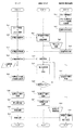
次に、上記の給電システムを運用する処理手順を図5のフローチャートに基づいて説明する。図5において、左列のフローはサーバの処理手順を示し、中列のフローは給電スタンドの処理手順を示し、右列のフローは端末機の処理手順を示す。また、各列のフロー間をつなぐ破線矢印は、通信網を介してサーバ、給電スタンド、端末機の相互でデータの通信がなされることを示す。以下の説明において、システムの各構成要素については、必要に応じて図1〜図3を参照する。
[System procedure]
Next, a processing procedure for operating the above power feeding system will be described based on the flowchart of FIG. In FIG. 5, the flow in the left column shows the processing procedure of the server, the flow in the middle row shows the processing procedure of the power supply station, and the flow in the right column shows the processing procedure of the terminal. A broken-line arrow connecting the flows in each column indicates that data is communicated between the server, the power supply station, and the terminal via the communication network. In the following description, FIGS. 1 to 3 are referred to as necessary for each component of the system.
(1)まず、ユーザは端末機20のカメラで使用する給電スタンド10のQRコードを撮影し、インターネットを介してサーバ30の携帯サイトにアクセスする(ステップSc1)。
(1) First, the user takes a QR code of the
(2)次に、端末機20から自己のID及びパスワードをサーバ30に送信し、ユーザ認証手段33によりユーザ認証を行う(ステップSs1)。このとき、給電制御手段36は、QRコードの読み取りデータと記憶手段32のスタンド情報とを参照して、給電に供される給電スタンド10をサーバ30に認識させる。
(2) Next, the terminal 20 transmits its own ID and password to the
(3)ユーザ認証が承認されれば、端末機20がアクセスしているサイトの画面で、認証OKの通知がなされる(ステップSc2)。 (3) If the user authentication is approved, the authentication OK is notified on the screen of the site accessed by the terminal 20 (step Sc2).
(4)ユーザ認証と給電スタンド10の特定が済めば、サーバ30は給電準備指令を給電スタンド10に送信し(ステップSs2)、その指令を受信した給電スタンド10では、例えば準備状態を示す青ランプを点灯させる(ステップSe1)。
(4) When the user authentication and the specification of the
(5)給電スタンド10が準備状態となれば、充電ケーブル60で電動車両50と給電スタンド10を接続する(ステップSe2)。
(5) When the power supply stand 10 is in the ready state, the
(6)ユーザは端末機20でサーバ30に接続した状態で、サイト上の給電メニューから、例えば「1時間」、「8時間」、「フル充電」などの給電条件を選択し、給電開始要求を行う(ステップSc3)。
(6) With the terminal 20 connected to the
(7)サーバ30が給電開始要求を受信すると(ステップSs3)、給電スタンド10に給電開始指令を送信する(ステップSs4)。
(7) When the
(8)給電スタンド10は、サーバ30からの要求に応じて、登録電動車両50の車載電池に給電を開始する(ステップSe3)。その際、給電スタンド10では、充電中を示す赤色のランプが点灯する。
(8) In response to a request from the
(9)給電開始と共に、給電スタンド10では、電力量計測手段12により電力量の計測が行われ、スタンド側通信手段13を介して、その計測結果がサーバ30に送信される(ステップSe4)。
(9) At the start of power supply, at the
(10)電力量の計測結果を受信したサーバ30は、記憶手段32のテーブルから登録電動車両50に対応する車載電池の充電特性データを読み出し、このデータを計測結果と参照することで、充電進行状態を演算する。そして、その演算結果はサーバ側通信手段31を介して端末機20に送信される(ステップSs5)。この送信は電子メールにて行われる。
(10) The
(11)ユーザは、端末機20で電子メールを受信することにより、充電の進行状態を把握することができる(ステップSc4)。例えば、「充電終了まで約8時間です。」、「充電終了予定時刻は、○○日のAM6:00です。」、或いは「充電率50%までの所要時間は約4時間です。」などの通知を受けることができる。この段階で、充電時間、充電終了時の充電率などの充電条件を変更したい場合は、前記電子メールにサーバ30へアクセスするURLを表示しておくことで、ユーザは端末機20によりそのURLからサーバ30にアクセスして、現在進行中の充電の条件を変更することができる。例えば、当初は充電率を「50%」と設定したが、この充電率を「フル充電」に変更したい場合、上述したサーバ30へのアクセスにより、充電条件を変更することができる。充電条件が変更されると、その旨、及び変更後の条件に応じた充電進行状態が電子メールにより通知される。
(11) The user can grasp the progress of charging by receiving an e-mail at the terminal 20 (step Sc4). For example, “It is about 8 hours until the end of charging.”, “The scheduled end time of charging is AM 6:00 on the XX day.” Or “The required time to charge
(12)この給電スタンド10による電力量の計測とサーバ30による充電進行状態の演算は、必要に応じて繰り返し行って、充電進行状態を適宜な間隔で、ユーザの端末機20に複数回通知するようにしてもよい。
(12) The measurement of the amount of power by the
(13)給電スタンド10では、車載電池の充電が終了したか否かを判断する(ステップSe5)。通常、電動車両は、車載電池の充電が終了すれば、電動車両側から受電を遮断する機能を有しており、この電動車両側からの受電の遮断(電力量計測手段12での計測電力量がゼロになる)、或いは給電メニューから選択した充電時間の経過などにより、給電スタンド10はスイッチ手段11をオフにすることで充電を終了させることができる。
(13) In the
(14)車載電池への給電を停止して充電が終了すると、給電スタンド10のスタンド制御手段14によりスタンド側通信手段13を介して給電完了通知がサーバ30に送信される(ステップSe6)。その際、給電スタンド10では、充電終了を示す緑ランプが点灯する。サーバ30では、給電スタンド10からの給電完了通知を受信する(ステップSs6)。
(14) When power supply to the in-vehicle battery is stopped and charging is completed, a power supply completion notification is transmitted to the
(15)また、給電スタンド10からは充電終了までの利用電力量をサーバ30に送信し(ステップSe7)、サーバ30では、この利用電力量を受信する(ステップSs7)。
(15) In addition, the power consumption until the end of charging is transmitted from the
(16)サーバ30は、この受信した利用電力量と記憶手段32より読み出した料金情報の単価を元に料金演算手段35で利用料金を算出する(ステップSs8)。
(16) The
(17)この時点で、給電スタンド10における処理は終了しているため、ユーザは充電コードを給電スタンド10から取り外すことができる(ステップSe8)。
(17) At this point, since the process in the
(18)一方、サーバ30では、演算された利用料金と共に、充電完了通知をユーザの端末機20に電子メールで送信する(ステップSs9)。
(18) On the other hand, the
(19)ユーザは、端末機20の電子メールを確認することで、充電が終了したことに加え、いつの充電において、どの程度の電力使用量で、利用料金がいくらであったかを知ることができる(ステップSc4)。この段階で、電池容量が100%でなく、さらに追加の充電を行いたい場合は、前記電子メールにサーバ30へアクセスするURLを表示しておくことで、ユーザは端末機20によりそのURLからサーバ30にアクセスして追加の充電条件を設定することで、さらに追加充電を行うことができる。その場合も、追加の充電条件にて充電が行われること、及びその条件に応じた充電進行状態が電子メールにより通知される。
(19) By checking the e-mail of the terminal 20, the user can know how much the usage fee was charged with what amount of power usage at the time of charging in addition to the completion of charging ( Step Sc4). At this stage, if the battery capacity is not 100% and further charging is desired, the URL for accessing the
〔作用効果〕
以上の給電システムによれば、次の作用効果を奏することができる。
[Function and effect]
According to the above power feeding system, the following operational effects can be achieved.
サーバ30がテーブルを含む電池情報と充電進行状態演算手段34とを有することで、予めユーザマスタ情報に登録された登録電動車両50の車載電池に応じた的確な充電進行状態を把握することができる。
Since the
給電スタンド10で把握できる充電電力を、充電器も含めた車載電池の充電電力カーブととらえ、その充電カーブを車載電池の充電カーブとみなすことで、電力線のみを備える低速充電用の充電ケーブル60であっても、車載電池の充電状態を把握することができる。 The charging power that can be grasped by the power supply stand 10 is regarded as the charging power curve of the in-vehicle battery including the charger, and the charging curve is regarded as the charging curve of the in-vehicle battery. Even if it exists, it can grasp | ascertain the charge condition of a vehicle-mounted battery.
低速充電を行う給電システムなので、給電スタンド10の設置に際して、高圧電源を引き込む必要はなく、低圧電源の利用により給電システムを構築できる。
Since the power supply system performs low-speed charging, it is not necessary to draw in a high-voltage power supply when installing the
ユーザ認証手段33を用いることで、利用料金の請求も行うことができ、給電システムの無断使用を排除することができる。 By using the user authentication means 33, a usage fee can be charged, and unauthorized use of the power supply system can be eliminated.
複数台の駐車スペースの各々に給電スタンド10を設置する場合、そのいずれかをサーバ30との通信機能を有する親機とし、残りを親機の通信機能を利用する子機とすることで、全ての給電スタンド10に通信機能を持たせる必要がない。また、給電スタンド自体にテーブルを含む電池情報と充電進行状態演算手段34とを持たせる必要もない。そのため、給電スタンド全体の構成を簡略化し、そのコストを低減することができる。
When the power supply stand 10 is installed in each of a plurality of parking spaces, any one of them is a master unit having a communication function with the
給電スタンド10に、給電中の充電ケーブル60の取り外しを阻止するロック機構を設けることで、ユーザの安全を確保すると共に、充電ケーブル60の盗難を防止することができる。
By providing the power supply stand 10 with a lock mechanism that prevents the removal of the charging
月極駐車場、マンションなどの集合住宅に付設される駐車場、或いは各種商業施設の駐車場などに本発明システムに対応した給電スタンド10を設置しておくことで、ユーザは電動車両50の充電機会を幅広く得ることができ、しかも充電進行状態や利用料金を給電スタンド10から離れても把握することができる。
By installing a
[変形例1-1]
実施形態1の変形例として、利用料金はクレジットカードで決済するようにしてもよい。その場合、ユーザ認証を行う際(図5のステップSs1)に、サーバ30からクレジット会社に対して与信認証を行うことが挙げられる。そして、料金演算手段35で求められた利用料金のデータは、図5のステップSs9において、ユーザの個人情報と共にサーバ30からクレジット会社に送信するよう構成すればよい。
[Modification 1-1]
As a modification of the first embodiment, the usage fee may be settled with a credit card. In that case, when user authentication is performed (step Ss1 in FIG. 5), credit authentication is performed from the
[変形例1-2]
実施形態1の変形例として、過去の充電履歴データを考慮して基準充電電力カーブを求めるようにしてもよい。統計処理手段37は、過去の充電履歴データを統計処理する。例えば、車載電池と充電器が同じ車種ごとに、充電履歴データを取得し、その充電履歴データを平均化して、その車種の基準充電電力データとする。充電履歴データは、車載電池の経年度合い(3年経過、5年経過など)ごとに分けて記憶しておき、その利用年数ごとに基準充電電力データを演算してもよい。車載電池の経年度合いは、車種の年式から算出できる。
[Modification 1-2]
As a modification of the first embodiment, a reference charging power curve may be obtained in consideration of past charging history data. The statistical processing means 37 statistically processes past charging history data. For example, the charging history data is acquired for each vehicle type in which the vehicle battery and the charger are the same, and the charging history data is averaged to obtain reference charging power data for the vehicle type. The charging history data may be stored separately for each aging degree (3 years, 5 years, etc.) of the in-vehicle battery, and the reference charging power data may be calculated for each usage year. The age of the onboard battery can be calculated from the model year.
この場合、統計処理手段により求められた基準充電電力データを用いることで、車載電池の経年変化に応じたより正確な充電進行状態の演算を行うことができる。また、車両ごとの充電電力のばらつきを平均化によりならすことができ、より適切な基準充電電力データを得ることができる。 In this case, by using the reference charging power data obtained by the statistical processing means, it is possible to calculate the charging progress state more accurately in accordance with the secular change of the in-vehicle battery. Further, variation in charging power for each vehicle can be smoothed by averaging, and more appropriate reference charging power data can be obtained.
[変形例1-3]
実施形態1の変形例として、充電進行状況演算手段34を利用して設定時間で充電できる電力量や充電率を演算したり、充電進行状況演算手段34と料金演算手段35との協働により、充電料金を先に設定して、その充電料金で充電できる電力量、さらには到達できる充電率を演算するようにしてもよい。
[Modification 1-3]
As a modification of the first embodiment, the charge progress status calculating means 34 is used to calculate the amount of power and the charge rate that can be charged in the set time, or by the cooperation between the charge progress status calculating means 34 and the charge calculating means 35, A charge charge may be set first, and the amount of power that can be charged with that charge charge, and further the charge rate that can be reached may be calculated.
前者の場合、例えば、1時間といった充電時間を設定する。その場合、端末機20からサーバ30にアクセスして、充電時間を設定する。1時間でどの程度の電力量を充電できるかは基準充電電力データを参照することで求められる。さらに、その1時間に充電できる電力量により、どの程度まで充電率を高められるかも基準充電電力データを参照して求めることができる。これは、実施形態1で述べたように、車載電池の充電を僅かに行うことで、車載電池の充電深度を予測することができるからである。従って、この参照結果をサーバ30から端末機20に送信することにより電子メール又は携帯サイトの画面にてユーザに知らせることができる。具体的には「1時間ですと、○○kwH利用可能です。」などのメッセージをサーバ30から端末機20に送信すればよい。
In the former case, for example, a charging time of 1 hour is set. In that case, the terminal 20 accesses the
後者の場合、例えば、200円でどの程度充電できるかを演算する。その場合、まず、端末機20から充電料金を設定して、サーバに送信する。サーバ30では、その設定充電料金(ここでは200円)を記憶手段32から読み出した料金単価で除することにより、その設定充電料金にて充電可能な電力量を演算する。この演算には料金演算手段35を利用すればよい。
In the latter case, for example, how much can be charged for 200 yen is calculated. In that case, first, the charging fee is set from the terminal 20 and transmitted to the server. The
実施形態1で述べたように、車載電池の充電を僅かに行うことで、車載電池の充電深度を予測することができる。そのため、設定充電料金で充電できる電力量を基準充電電力カーブと参照することで、さらにどの程度まで充電率を高められるかや、その電力量分を充電するための所要時間も予測することができる。そのため、設定充電料金にて充電可能な電力量や、その電力量の充電により達成できる充電率、或いはその電力量分を充電するための所要時間をサーバ30から端末機20に送信することにより電子メール又は携帯サイトの画面にてユーザに知らせることができる。具体的には、「200円での充電量は8kwHになり、約4時間かかります。充電完了時の充電率は約70%です。」などのメッセージをサーバから端末機に送信すればよい。
As described in the first embodiment, the charging depth of the in-vehicle battery can be predicted by slightly charging the in-vehicle battery. Therefore, by referring to the amount of power that can be charged at the set charge rate as the reference charging power curve, it is possible to predict how much the charging rate can be further increased and the time required to charge the amount of power. . Therefore, by transmitting the amount of power that can be charged at the set charge rate, the charging rate that can be achieved by charging the amount of power, or the time required to charge the amount of power to the terminal 20 from the
[変形例1-4]
実施形態1で述べたように、充電進行状態として充電終了時刻が予測できるため、各給電スタンド10ごとの充電終了予測時刻を給電スタンド10の空き情報として利用し、これから給電スタンド1を利用しようとするユーザに対して、この空き情報をサーバ30から端末機20に通知することができる。
[Modification 1-4]
As described in the first embodiment, since the charging end time can be predicted as the charging progress state, the charging end predicted time for each
例えば、ある給電スタンド10の充電終了予測時刻がある日のAM6:00であったとすると、AM6:00以降はその給電スタンド10が空き状態になることが把握できる。そのため、これから給電スタンド10を利用しようとするユーザが端末機20を介してサーバ30にアクセスし、どの地域のどの給電スタンド群かを選択すると、その給電スタンド群のうち、どの給電スタンド10がいつ頃空き状態となっているかを携帯サイトの画面を通じてユーザに知らせることができる。さらに、サーバ30が給電スタンド10の予約システムを持っている場合、空き状態を把握したユーザは、そのまま予約システムを利用して当該給電スタンド10の予約をすることもできる。
For example, if the estimated charging end time of a certain
[変形例1-5]
以上の実施形態1とその変形例では、車載電池の端子電圧や充電電流は直接給電スタンド10側で把握できないことが前提であった。但し、有線又は無線による適宜な通信手段を用いて車両側から給電スタンド側へ車載電池の充電に相関する物理量、例えば、端子電圧、充電電流、電池温度などを送信することができる場合、この端子電圧と充電時間との相関関係、充電電流と充電時間の相関関係などを充電特性データとして記憶して利用することで、より高精度の充電進行状態の予測を行うことができる。上記通信手段には、スタンド側通信手段を利用することができる。
[Modification 1-5]
The
[実施形態2]
実施形態1では、車載電池の充電進行状態をユーザに知らせることができたが、本例では、さらに登録電動車両の車載電池の劣化状態をもユーザに知らせることができる給電システムを説明する。本例のシステムは、図1のシステムと基本構成は共通であり、主な相違はサーバが電池状態判定手段を備え、記憶手段に過去の充電履歴データを記憶している点である。そのため、以下の説明は相違点を中心に行う。
[Embodiment 2]
In the first embodiment, the charging progress state of the in-vehicle battery can be notified to the user. However, in this example, a power supply system that can also notify the user of the deterioration state of the in-vehicle battery of the registered electric vehicle will be described. The system of this example has the same basic configuration as the system of FIG. 1, and the main difference is that the server includes battery state determination means, and the past charging history data is stored in the storage means. Therefore, the following description will focus on the differences.
〔システムの概要〕
このシステムは、例えば記憶手段32のユーザマスタ情報の一つとして、過去の充電履歴データを記憶すると共に、図3に破線枠で示すように、電池状態判定手段38を備えている。過去の充電履歴データは、過去の車載電池の充電において、給電スタンド10(図1、図2)からサーバ30(図1)に送られてきた電力量の計測結果であり、充電時間と電力量の相関関係が含まれる。一方、二次電池は、一般に充放電サイクルを繰り返すと、電池容量が低下したり、電池抵抗が増加したりする傾向があり、一定以上の電池容量の低下などが生じると、電池の交換が必要になる。例えば、劣化のない電池であれば、単位時間当たりの充電電力の変位が大きいにもかかわらず、劣化した電池では、その変位が小さくなったりする。そのため、電池状態判定手段38により、最新の充電履歴データを過去の充電履歴データや劣化のない車載電池の充電特性データ(基準充電電力カーブを含む)と対比することで車載電池の劣化状態を判定することができる。具体的には対比対象データの間に所定の許容範囲を超える乖離が認められた場合、車載電池が劣化していると判定し、その乖離が許容範囲内の場合は劣化がないと判定する。その判定結果は、サーバ側通信手段31を介して、充電終了や利用料金を通知する際(図5のステップSc4)に、電子メールにて併せて通知される。具体的には。「電池が劣化しています。点検の上、取り換えをご検討ください。」などのメッセージを通知する。
[System Overview]
This system stores, for example, past charging history data as one of user master information in the storage means 32, and also includes a battery state determination means 38 as indicated by a broken line frame in FIG. The past charging history data is the measurement result of the amount of power sent from the power supply station 10 (Figs. 1 and 2) to the server 30 (Fig. 1) during past charging of the on-board battery. Correlations are included. On the other hand, secondary batteries generally tend to decrease in battery capacity or increase in battery resistance when the charge / discharge cycle is repeated. If the battery capacity decreases more than a certain level, the battery needs to be replaced. become. For example, if the battery has no deterioration, the displacement of the deteriorated battery may be small even though the displacement of the charging power per unit time is large. Therefore, the battery state determination means 38 determines the deterioration state of the in-vehicle battery by comparing the latest charging history data with the past charging history data and the charging characteristic data of the in-vehicle battery without deterioration (including the reference charging power curve). can do. Specifically, when a deviation exceeding a predetermined allowable range is recognized between the comparison target data, it is determined that the in-vehicle battery has deteriorated, and when the deviation is within the allowable range, it is determined that there is no deterioration. The determination result is also notified by e-mail when the charging end or usage fee is notified via the server side communication means 31 (step Sc4 in FIG. 5). In particular. A message such as "Battery has deteriorated. Please consider replacing it after inspection."
〔作用効果〕
本例の実施形態によれば、過去の充電履歴データをサーバ30に保有しておき、最新の充電履歴データを過去の充電履歴データや劣化のない車載電池の充電特性データと対比することで車載電池の劣化状態を検知することができる。その検知状態は、サーバ30から端末機20を介してユーザに通知されるため、ユーザは車載電池の交換時期を知ることができる。
[Function and effect]
According to the embodiment of the present example, the past charging history data is held in the
[変形例2-1]
変形例1-2で述べた統計処理手段37の処理結果は、電池状態の劣化を判定することにも利用することができる。つまり、変形例1-2と同様に、車載電池と充電器が同じ車種ごとに、充電履歴データを取得し、その充電履歴データを平均化して、その車種の基準充電電力データとする。充電履歴データは、車載電池の経年度合い(3年経過、5年経過など)ごとに分けて記憶しておき、その利用年数ごとに基準充電電力データを演算してもよい。
[Modification 2-1]
The processing result of the statistical processing means 37 described in Modification 1-2 can also be used to determine the deterioration of the battery state. That is, as in Modification 1-2, the charging history data is acquired for each vehicle model in which the vehicle-mounted battery and the charger are the same, and the charging history data is averaged to obtain reference charging power data for the vehicle model. The charging history data may be stored separately for each aging degree (3 years, 5 years, etc.) of the in-vehicle battery, and the reference charging power data may be calculated for each usage year.
そして、実施形態2と同様に、電池状態判定手段38は、最新の充電履歴データとの比較対象として、統計処理手段37で統計処理された基準充電電力データを用いる。これにより、同車種の他のユーザと比較して自分の車載電池がどの程度劣化しているかといった比較判定も行うことができる。勿論、その判定結果は、電子メールにてサーバ30から端末機20に送られ、ユーザに知らされる。或いは、サーバ30にアクセスした携帯サイトの画面にて上記判定結果をユーザに知らせることもできる。
As in the second embodiment, the battery
[実施形態3]
実施形態1では、給電システムの給電対象が登録電動車両に限られているが、本例では、登録電動車両以外の電動車両に対しても給電が可能な給電システムを説明する。本例でも基本構成は図1のシステムと共通であるため、相違点を中心に以下に説明する。
[Embodiment 3]
In the first embodiment, the power supply target of the power supply system is limited to the registered electric vehicle, but in this example, a power supply system capable of supplying power to an electric vehicle other than the registered electric vehicle will be described. In this example, the basic configuration is the same as that of the system shown in FIG.
〔システムの概要〕
例えば、ユーザの登録電動車両50がトヨタ製プリウスだが、ユーザの友人が所有するホンダ製インサイトの車載電池に充電を行いたい場合、通常は車種によって車載電池の仕様も異なるため、的確な充電進行状態の把握を行うには、給電対象となる車載電池に応じた充電特性データが必要になる。
[System Overview]
For example, if the user's registered
この場合、ユーザ認証を行う際(図5のステップSs1)などに、さらに給電対象の車種を選択できるようにすればよい。一般に、電動車両の運転者は自己の電動車両の車種程度は把握しているが、その車載電池の種類についてまでは把握していないことが多い。一方、記憶手段32のテーブルには、登録電動車両を含む各カーメーカの車種(必要に応じて年式)とその車種の車載電池の充電特性データとの対応関係を記憶させておく。それにより、ユーザに給電対象の車種を選択させれば、その車載電池の充電特性データもテーブルから抽出することができる。これにより、充電進行状態演算手段34が参照する充電特性データは、給電対象となる車載電池の種類に応じた適切な充電特性データを利用することができる。さらに、実施形態2や変形例2-1と同様に電池状態判定手段38を用いることで、登録電動車両以外の車両に対しても車載電池の劣化程度を評価することができる。
In this case, when performing user authentication (step Ss1 in FIG. 5) and the like, it is only necessary to further select a vehicle type to be supplied with power. In general, a driver of an electric vehicle knows the vehicle type of his / her own electric vehicle, but often does not know the type of in-vehicle battery. On the other hand, in the table of the storage means 32, the correspondence relationship between the car type of each car maker including the registered electric vehicle (year if necessary) and the charging characteristic data of the in-vehicle battery of that car type is stored. Thereby, if the user selects a vehicle type to be supplied with power, the charging characteristic data of the in-vehicle battery can be extracted from the table. As a result, the charging characteristic data referred to by the charging progress state calculating means 34 can use appropriate charging characteristic data corresponding to the type of the in-vehicle battery to be fed. Further, by using the battery
なお、充電終了や利用料金の通知対象者及び利用料金の請求対象者は登録されているユーザに対して行われる。もっとも、ユーザマスタ情報として、電子メールアドレスを複数登録しておき、その複数のアドレスからユーザの友人のアドレスを選択できるようにすれば、充電終了や利用料金の通知対象者をユーザの友人にすることも可能である。 It should be noted that the charging completion and usage charge notification target person and the usage charge charge target person are performed for registered users. However, if a plurality of e-mail addresses are registered as the user master information and the address of the user's friend can be selected from the plurality of addresses, the person to be notified of the charge termination or usage fee is made the user's friend. It is also possible.
〔作用効果〕
本例の実施形態によれば、ユーザが給電システムの使用を許可した電動車両に限られるが、給電対象が登録電動車両50以外の電動車両であっても、その電動車両の車載電池に応じた的確な充電進行状態を把握することができる。
[Function and effect]
According to the embodiment of the present example, the user is limited to the electric vehicle for which the use of the power supply system is permitted, but even if the power supply target is an electric vehicle other than the registered
本発明は上記実施形態に限定されるものではなく、本発明の要旨を逸脱しない範囲内において、種々の形態で実施し得ることは言うまでもない。例えば、実施形態1では、給電スタンドの一つを親機とし、残りを子機としたが、複数ある給電スタンドの全てを親機としてもよい。また、本発明の範囲は、特許請求の範囲によって示され、さらに特許請求の範囲と均等な範囲内のすべての変更を含む。 It goes without saying that the present invention is not limited to the above-described embodiment, and can be implemented in various forms without departing from the gist of the present invention. For example, in the first embodiment, one of the power supply stands is a master unit and the rest is a slave unit. However, all of the plurality of power supply stations may be the master unit. The scope of the present invention is defined by the terms of the claims, and includes all modifications within the scope equivalent to the terms of the claims.
本発明の給電システムは、電動車両の車載電池を充電するための給電スタンドの運用に好適に利用することができる。 The power supply system of the present invention can be suitably used for the operation of a power supply stand for charging an in-vehicle battery of an electric vehicle.
1 電動車両用給電システム
10 給電スタンド
11 スイッチ手段 12 電力量計測手段 13 スタンド側通信手段
14 スタンド制御手段 15 識別コード 16 コンセント
20 端末機
30 サーバ
31 サーバ側通信手段 32 記憶手段 33 ユーザ認証手段
34 充電進行状態演算手段 35 料金演算手段 36 給電制御手段
37 統計処理手段 38 電池状態判定手段 39 システム制御手段
50 電動車両
60 充電ケーブル
1 Electric vehicle power supply system
10 Power supply stand
11 Switch means 12 Electric energy measuring means 13 Stand side communication means
14 Stand control means 15
20 terminal
30 servers
31 Server side communication means 32 Storage means 33 User authentication means
34 Charging progress state calculation means 35 Charge calculation means 36 Power supply control means
37 Statistical processing means 38 Battery status judgment means 39 System control means
50 electric vehicle
60 Charging cable
本発明の電動車両用給電システムは、電動車両の車載電池に給電するための給電スタンドと、この給電スタンド及び当該給電スタンドのユーザが利用する端末機の各々と通信網を介して通信するサーバとを備える。前記給電スタンドは、前記端末機からのサーバを介した要求に応じて、車載電池への給電を行うスイッチ手段と、前記車載電池に給電した電力量を計測する電力量計測手段とを有する。前記サーバは、記憶手段と、ユーザ認証手段と、充電進行状態演算手段とを備える。この記憶手段は、前記ユーザとその登録電動車両とを特定するためのユーザマスタ情報とテーブルとを有する。テーブルは、登録電動車両と、その車載電池の充電特性データであって前記電力量計測手段で取得できる物理量の特性データとを関連付ける。ユーザ認証手段は、前記端末機から送信されたユーザ入力情報と前記ユーザマスタ情報とを参照して、ユーザの認証を行う。そして、充電進行状態演算手段は、認証されたユーザの登録電動車両に対応する充電特性データを前記テーブルから抽出し、前記給電スタンドから送信された電力量計測手段の計測データを抽出された充電特性データと参照して車載電池の充電進行状態を演算し、この演算結果を端末機に送信するための充電進行状態データとして生成する。 A power supply system for an electric vehicle according to the present invention includes a power supply stand for supplying power to an in-vehicle battery of the electric vehicle, and a server that communicates with each of the power supply stand and a terminal used by a user of the power supply stand via a communication network. Is provided. The power supply stand includes switch means for supplying power to the in-vehicle battery in response to a request from the terminal via the server, and power amount measuring means for measuring the amount of power supplied to the in-vehicle battery. The server includes a storage unit, a user authentication unit, and a charging progress state calculation unit. The storage means includes user master information and a table for identifying the user and the registered electric vehicle. The table associates the registered electric vehicle with the characteristic data of the physical quantity that can be acquired by the electric energy measuring means, which is the charging characteristic data of the in-vehicle battery. The user authentication means authenticates the user with reference to the user input information transmitted from the terminal and the user master information. Then, the charging progress state calculation means extracts charging characteristic data corresponding to the registered electric vehicle of the authenticated user from the table, and the charging characteristic obtained by extracting the measurement data of the electric energy measuring means transmitted from the power supply stand The charging progress state of the in-vehicle battery is calculated with reference to the data, and the calculation result is generated as charging progress state data for transmitting to the terminal.
[実施形態1]
〔システムの構成〕
{概要}
この電動車両用給電システム1は、図1に示すように、月極駐車場などの駐車場に設置された給電スタンド10と、この給電スタンド10及び当該給電スタンド10のユーザが利用する端末機20の各々と通信網を介して通信するサーバ30とを主たる構成要素とする。この給電システム1を利用する際、ユーザは端末機20を保有すると共に、駐車場に登録電動車両50を駐車し、充電ケーブル60で給電スタンド10と車載電池とを接続して、端末機20からサーバ30を介した要求により、給電スタンド10から車載電池に給電させる。登録電動車両50とは、予めユーザの個人情報と共に車両情報をサーバ30に登録している電動車両のことである。この給電に伴い車載電池は充電され、給電スタンド10にて充電に要した電力量が計測される。その計測結果は給電スタンド10からサーバ30に送信され、サーバ30にて充電進行状態の演算に供されると共に、充電終了時には前記電力量に基づいて給電システムの利用料金が算出される。充電の進行状態や前記利用料金は、サーバ30から端末機20に送信されることで、ユーザに知らされる。以下、各部の構成を詳しく説明する。
[Embodiment 1]
[System configuration]
{Overview}
As shown in FIG. 1, the electric vehicle
Claims (8)
この給電スタンドのユーザが利用する端末機と、
前記給電スタンド及び端末機の各々と通信網を介して通信するサーバとを備え、
前記給電スタンドは、
前記端末機からのサーバを介した要求に応じて、車載電池への給電を行うスイッチ手段と、
前記車載電池に給電した電力量を計測する電力量計測手段とを有し、
前記サーバは、
前記ユーザとその登録電動車両とを特定するためのユーザマスタ情報と、この登録電動車両とその車載電池の充電特性データであって前記電力量計測手段で取得できる物理量の特性データとを関連付けるテーブルとを有する記憶手段と、
前記端末機から送信されたユーザ入力情報と前記ユーザマスタ情報とを参照して、ユーザの認証を行うユーザ認証手段と、
認証されたユーザの登録電動車両に対応する充電特性データを前記テーブルから抽出し、前記給電スタンドから送信された電力量計測手段の計測データを抽出された充電特性データと参照して車載電池の充電進行状態を演算し、この演算結果を端末機に送信するための充電進行状態データとして生成する充電進行状態演算手段とを有することを特徴とする電動車両用給電システム。 A power supply stand for supplying power to the vehicle-mounted battery of the electric vehicle;
A terminal used by a user of the power supply stand;
A server that communicates with each of the power supply station and the terminal via a communication network;
The power supply stand is
In response to a request from the terminal via the server, switch means for supplying power to the in-vehicle battery,
Having an electric energy measuring means for measuring the electric energy supplied to the in-vehicle battery,
The server
A table for associating user master information for identifying the user and the registered electric vehicle, and characteristic data of the physical quantity that can be acquired by the electric energy measuring means, which is charging characteristic data of the registered electric vehicle and the in-vehicle battery. Storage means having
User authentication means for authenticating a user with reference to the user input information transmitted from the terminal and the user master information;
Charging the vehicle battery by extracting charging characteristic data corresponding to the registered electric vehicle of the authenticated user from the table and referring to the measurement data of the electric energy measuring means transmitted from the power supply stand with the extracted charging characteristic data A power supply system for an electric vehicle, comprising: a charge progress state calculation unit that calculates a progress state and generates charging progress state data for transmitting the calculation result to a terminal.
さらに、前記サーバは、最新の充電履歴データを過去の充電履歴データや劣化のない車載電池の充電特性データと対比することで、車載電池の劣化状況を判定し、この判定結果を端末機に送信するための判定結果データとして生成する電池状態判定手段を備えることを特徴とする請求項1又は2に記載の電動車両用給電システム。 The storage means stores the charge history data measured by the power amount measuring means in the past power supply by the user,
Furthermore, the server compares the latest charging history data with the past charging history data and the charging characteristic data of the in-vehicle battery without deterioration, thereby determining the deterioration state of the in-vehicle battery, and transmits the determination result to the terminal. The power supply system for an electric vehicle according to claim 1, further comprising: a battery state determination unit that generates as determination result data for performing the operation.
前記充電進行状態演算手段は、抽出された充電特性データとして、統計処理手段で統計処理された充電履歴データを用いることを特徴とする請求項1〜3のいずれか1項に記載の電動車両用給電システム。 The server includes statistical processing means for statistically processing the charging history data measured by the power amount measuring means in the past power supply for each vehicle type of the registered electric vehicle,
4. The electric vehicle according to claim 1, wherein the charging progress state calculating unit uses charging history data statistically processed by the statistical processing unit as the extracted charging characteristic data. 5. Power supply system.
前記電池状態判定手段は、最新の充電履歴データとの比較対象として、統計処理手段で統計処理された充電履歴データを用いることを特徴とする請求項3に記載の電動車両用給電システム。 The server includes statistical processing means for statistically processing the charging history data measured by the power amount measuring means in the past power supply for each vehicle type of the registered electric vehicle,
The power supply system for an electric vehicle according to claim 3, wherein the battery state determination unit uses the charging history data statistically processed by the statistical processing unit as a comparison target with the latest charging history data.
前記充電進行状態演算手段は、給電対象となる電動車両が前記登録電動車両と異なる場合に、端末機を介して前記テーブルから選択された電動車両に対応する充電特性データを抽出することを特徴とする請求項1〜5のいずれか1項に記載の電動車両用給電システム。 The storage means further stores charging characteristic data of an electric vehicle other than the registered electric vehicle,
The charging progress state calculating means extracts charging characteristic data corresponding to the electric vehicle selected from the table via a terminal when the electric vehicle to be fed is different from the registered electric vehicle. The electric vehicle power supply system according to any one of claims 1 to 5.
前記充電進行状態演算手段は、充電進行状態データとして、前記電力量計測手段で取得できる物理量の特性データの代わりに、又は前記特性データに加味して前記物理量を利用することを特徴とする請求項1〜6のいずれか1項に記載の電動車両用給電システム。 The power supply stand includes a stand side communication means for receiving a physical quantity correlated with the charge of the in-vehicle battery transmitted from the registered vehicle side,
The charging progress state calculation means uses the physical quantity as charging progress state data instead of the physical quantity characteristic data that can be acquired by the power amount measuring means or in addition to the characteristic data. The power feeding system for an electric vehicle according to any one of 1 to 6.
Priority Applications (2)
| Application Number | Priority Date | Filing Date | Title |
|---|---|---|---|
| JP2010028180A JP4954304B2 (en) | 2010-02-10 | 2010-02-10 | Electric vehicle power supply system |
| JP2012054788A JP5489302B2 (en) | 2010-02-10 | 2012-03-12 | Electric vehicle power supply system |
Applications Claiming Priority (2)
| Application Number | Priority Date | Filing Date | Title |
|---|---|---|---|
| JP2010028180A JP4954304B2 (en) | 2010-02-10 | 2010-02-10 | Electric vehicle power supply system |
| JP2012054788A JP5489302B2 (en) | 2010-02-10 | 2012-03-12 | Electric vehicle power supply system |
Related Parent Applications (1)
| Application Number | Title | Priority Date | Filing Date |
|---|---|---|---|
| JP2010028180A Division JP4954304B2 (en) | 2010-02-10 | 2010-02-10 | Electric vehicle power supply system |
Publications (2)
| Publication Number | Publication Date |
|---|---|
| JP2012161241A true JP2012161241A (en) | 2012-08-23 |
| JP5489302B2 JP5489302B2 (en) | 2014-05-14 |
Family
ID=51625730
Family Applications (2)
| Application Number | Title | Priority Date | Filing Date |
|---|---|---|---|
| JP2010028180A Expired - Fee Related JP4954304B2 (en) | 2010-02-10 | 2010-02-10 | Electric vehicle power supply system |
| JP2012054788A Expired - Fee Related JP5489302B2 (en) | 2010-02-10 | 2012-03-12 | Electric vehicle power supply system |
Family Applications Before (1)
| Application Number | Title | Priority Date | Filing Date |
|---|---|---|---|
| JP2010028180A Expired - Fee Related JP4954304B2 (en) | 2010-02-10 | 2010-02-10 | Electric vehicle power supply system |
Country Status (1)
| Country | Link |
|---|---|
| JP (2) | JP4954304B2 (en) |
Cited By (4)
| Publication number | Priority date | Publication date | Assignee | Title |
|---|---|---|---|---|
| CN103023100A (en) * | 2012-11-13 | 2013-04-03 | 江苏科技大学 | Electric bicycle storage battery management system and method based on Internet of Things |
| JP2014131468A (en) * | 2012-12-20 | 2014-07-10 | Lsis Co Ltd | Method of operating charging apparatus |
| WO2015046656A1 (en) * | 2013-09-30 | 2015-04-02 | 한국전력공사 | Apparatus and method for economically charging electronic vehicle |
| US11027621B2 (en) | 2018-04-20 | 2021-06-08 | Toyota Jidosha Kabushiki Kaisha | Vehicle and charging system |
Families Citing this family (14)
| Publication number | Priority date | Publication date | Assignee | Title |
|---|---|---|---|---|
| JP5409717B2 (en) * | 2011-07-12 | 2014-02-05 | トヨタ自動車株式会社 | Data collection method and data collection system |
| NL2007560C2 (en) * | 2011-10-10 | 2013-04-11 | Epyon B V | System and method for remote monitoring of charging the battery of an electric vehicle, charger and device for use in the system and method. |
| WO2013057879A1 (en) | 2011-10-20 | 2013-04-25 | パナソニック株式会社 | Automobile charge control device and information terminal |
| US8521599B2 (en) * | 2011-10-28 | 2013-08-27 | General Electric Company | Charging system, kiosk, and method of reserving a power charging device and supplying current to a power storage device |
| JP5861135B2 (en) * | 2011-12-28 | 2016-02-16 | 旭精工株式会社 | Electricity fee settlement system and electric vehicle charging fee settlement system |
| JP2013158145A (en) * | 2012-01-30 | 2013-08-15 | Toyota Industries Corp | Charging system |
| JP2013178594A (en) * | 2012-02-10 | 2013-09-09 | Enegate:Kk | Power supplying system for electric vehicle |
| JP2014003744A (en) * | 2012-06-15 | 2014-01-09 | Takaoka Electric Mfg Co Ltd | Remote monitoring and control system of charger for electric vehicle |
| JP5665813B2 (en) * | 2012-08-22 | 2015-02-04 | オムロンオートモーティブエレクトロニクス株式会社 | Control system for supplying fuel to vehicles, portable devices |
| JP2014053173A (en) * | 2012-09-07 | 2014-03-20 | Nissan Motor Co Ltd | System for predicting battery deterioration |
| US9772383B2 (en) | 2015-03-04 | 2017-09-26 | Johnson Controls Technology Company | Battery test report system and method |
| JP2020139298A (en) | 2019-02-27 | 2020-09-03 | 本田技研工業株式会社 | Vehicle transportation system |
| WO2021196045A1 (en) * | 2020-03-31 | 2021-10-07 | 华为技术有限公司 | Method and apparatus for predicting charging progress of battery |
| JP2023019449A (en) | 2021-07-29 | 2023-02-09 | トヨタ自動車株式会社 | Power system and power calculation method |
Citations (5)
| Publication number | Priority date | Publication date | Assignee | Title |
|---|---|---|---|---|
| JP2004048900A (en) * | 2002-07-11 | 2004-02-12 | Denso Corp | Charging system and computer program for electric vehicle |
| JP2006250905A (en) * | 2005-03-14 | 2006-09-21 | Fuji Heavy Ind Ltd | Battery management system |
| JP2009089452A (en) * | 2007-09-27 | 2009-04-23 | Denso Corp | Charging system |
| JP2009118652A (en) * | 2007-11-07 | 2009-05-28 | Chugoku Electric Power Co Inc:The | Charging system for electric vehicle |
| JP2010022099A (en) * | 2008-07-09 | 2010-01-28 | Toyota Motor Corp | Parking system |
-
2010
- 2010-02-10 JP JP2010028180A patent/JP4954304B2/en not_active Expired - Fee Related
-
2012
- 2012-03-12 JP JP2012054788A patent/JP5489302B2/en not_active Expired - Fee Related
Patent Citations (5)
| Publication number | Priority date | Publication date | Assignee | Title |
|---|---|---|---|---|
| JP2004048900A (en) * | 2002-07-11 | 2004-02-12 | Denso Corp | Charging system and computer program for electric vehicle |
| JP2006250905A (en) * | 2005-03-14 | 2006-09-21 | Fuji Heavy Ind Ltd | Battery management system |
| JP2009089452A (en) * | 2007-09-27 | 2009-04-23 | Denso Corp | Charging system |
| JP2009118652A (en) * | 2007-11-07 | 2009-05-28 | Chugoku Electric Power Co Inc:The | Charging system for electric vehicle |
| JP2010022099A (en) * | 2008-07-09 | 2010-01-28 | Toyota Motor Corp | Parking system |
Cited By (5)
| Publication number | Priority date | Publication date | Assignee | Title |
|---|---|---|---|---|
| CN103023100A (en) * | 2012-11-13 | 2013-04-03 | 江苏科技大学 | Electric bicycle storage battery management system and method based on Internet of Things |
| JP2014131468A (en) * | 2012-12-20 | 2014-07-10 | Lsis Co Ltd | Method of operating charging apparatus |
| WO2015046656A1 (en) * | 2013-09-30 | 2015-04-02 | 한국전력공사 | Apparatus and method for economically charging electronic vehicle |
| EP3054552A4 (en) * | 2013-09-30 | 2016-11-02 | Korea Electric Power Corp | Apparatus and method for economically charging electronic vehicle |
| US11027621B2 (en) | 2018-04-20 | 2021-06-08 | Toyota Jidosha Kabushiki Kaisha | Vehicle and charging system |
Also Published As
| Publication number | Publication date |
|---|---|
| JP2011166971A (en) | 2011-08-25 |
| JP5489302B2 (en) | 2014-05-14 |
| JP4954304B2 (en) | 2012-06-13 |
Similar Documents
| Publication | Publication Date | Title |
|---|---|---|
| JP5489302B2 (en) | Electric vehicle power supply system | |
| US10546438B2 (en) | Apparatus, method and article for providing vehicle diagnostic data | |
| JP6114531B2 (en) | Charging system, kiosk, and method of supplying current to a power storage device | |
| US10055911B2 (en) | Apparatus, method and article for authentication, security and control of power storage devices, such as batteries, based on user profiles | |
| JP5152644B2 (en) | Electric drive charging system and method | |
| JP2019071780A (en) | User authentication outlet or connector, power intermediary connector, and power demand device | |
| WO2018104965A1 (en) | Battery swapping systems and methods | |
| US20140354235A1 (en) | Embedded device for controlling communication with vehicle and method for actuating same | |
| US20140312847A1 (en) | Apparatus for controlling home communication | |
| KR101501918B1 (en) | A Remote Metering System for the Recharge of an Electric Vehicle | |
| US11279251B2 (en) | Charging system | |
| JP2012098798A (en) | Charging system | |
| KR20180007765A (en) | Charging method of settlement costs differentiated charging according to Charging Service Mode and Rapid Charging System | |
| KR20130015373A (en) | Sharing electric vehicle charge and accounting system and method | |
| KR101769467B1 (en) | Electric car charging and cost calcuating system | |
| JP5503997B2 (en) | Electric vehicle power supply system, electric vehicle power supply method, and electric vehicle power supply program | |
| WO2011021973A1 (en) | Method of electrical charging | |
| US20190152328A1 (en) | Replacement fee setting apparatus, method and system | |
| EP3960531A1 (en) | A system for processing a charging fee of an electric vehicle with a mobile device and a method for utilizing a charging data with the same | |
| JP2022183306A (en) | Method and device for identifying battery type of electric car | |
| US11657658B2 (en) | Information providing server, information providing system, and recording medium | |
| KR20230000479U (en) | Car battery monitoring system | |
| KR102297931B1 (en) | Meters identification method for charging of electric vehicle | |
| KR102395249B1 (en) | Electric vehicle charging and billing method | |
| JP2017016547A (en) | Charging accounting system of electric automobile |
Legal Events
| Date | Code | Title | Description |
|---|---|---|---|
| A621 | Written request for application examination |
Free format text: JAPANESE INTERMEDIATE CODE: A621 Effective date: 20130118 |
|
| TRDD | Decision of grant or rejection written | ||
| A01 | Written decision to grant a patent or to grant a registration (utility model) |
Free format text: JAPANESE INTERMEDIATE CODE: A01 Effective date: 20140219 |
|
| A61 | First payment of annual fees (during grant procedure) |
Free format text: JAPANESE INTERMEDIATE CODE: A61 Effective date: 20140221 |
|
| R150 | Certificate of patent or registration of utility model |
Ref document number: 5489302 Country of ref document: JP Free format text: JAPANESE INTERMEDIATE CODE: R150 |
|
| R250 | Receipt of annual fees |
Free format text: JAPANESE INTERMEDIATE CODE: R250 |
|
| R250 | Receipt of annual fees |
Free format text: JAPANESE INTERMEDIATE CODE: R250 |
|
| R250 | Receipt of annual fees |
Free format text: JAPANESE INTERMEDIATE CODE: R250 |
|
| LAPS | Cancellation because of no payment of annual fees |