JP2013106363A - Lock control device - Google Patents
Lock control device Download PDFInfo
- Publication number
- JP2013106363A JP2013106363A JP2011246308A JP2011246308A JP2013106363A JP 2013106363 A JP2013106363 A JP 2013106363A JP 2011246308 A JP2011246308 A JP 2011246308A JP 2011246308 A JP2011246308 A JP 2011246308A JP 2013106363 A JP2013106363 A JP 2013106363A
- Authority
- JP
- Japan
- Prior art keywords
- charging
- electric vehicle
- charger
- lock
- emergency
- Prior art date
- Legal status (The legal status is an assumption and is not a legal conclusion. Google has not performed a legal analysis and makes no representation as to the accuracy of the status listed.)
- Pending
Links
Images


Classifications
-
- Y—GENERAL TAGGING OF NEW TECHNOLOGICAL DEVELOPMENTS; GENERAL TAGGING OF CROSS-SECTIONAL TECHNOLOGIES SPANNING OVER SEVERAL SECTIONS OF THE IPC; TECHNICAL SUBJECTS COVERED BY FORMER USPC CROSS-REFERENCE ART COLLECTIONS [XRACs] AND DIGESTS
- Y02—TECHNOLOGIES OR APPLICATIONS FOR MITIGATION OR ADAPTATION AGAINST CLIMATE CHANGE
- Y02E—REDUCTION OF GREENHOUSE GAS [GHG] EMISSIONS, RELATED TO ENERGY GENERATION, TRANSMISSION OR DISTRIBUTION
- Y02E60/00—Enabling technologies; Technologies with a potential or indirect contribution to GHG emissions mitigation
- Y02E60/10—Energy storage using batteries
-
- Y—GENERAL TAGGING OF NEW TECHNOLOGICAL DEVELOPMENTS; GENERAL TAGGING OF CROSS-SECTIONAL TECHNOLOGIES SPANNING OVER SEVERAL SECTIONS OF THE IPC; TECHNICAL SUBJECTS COVERED BY FORMER USPC CROSS-REFERENCE ART COLLECTIONS [XRACs] AND DIGESTS
- Y02—TECHNOLOGIES OR APPLICATIONS FOR MITIGATION OR ADAPTATION AGAINST CLIMATE CHANGE
- Y02T—CLIMATE CHANGE MITIGATION TECHNOLOGIES RELATED TO TRANSPORTATION
- Y02T90/00—Enabling technologies or technologies with a potential or indirect contribution to GHG emissions mitigation
- Y02T90/10—Technologies relating to charging of electric vehicles
- Y02T90/16—Information or communication technologies improving the operation of electric vehicles
- Y02T90/167—Systems integrating technologies related to power network operation and communication or information technologies for supporting the interoperability of electric or hybrid vehicles, i.e. smartgrids as interface for battery charging of electric vehicles [EV] or hybrid vehicles [HEV]
-
- Y—GENERAL TAGGING OF NEW TECHNOLOGICAL DEVELOPMENTS; GENERAL TAGGING OF CROSS-SECTIONAL TECHNOLOGIES SPANNING OVER SEVERAL SECTIONS OF THE IPC; TECHNICAL SUBJECTS COVERED BY FORMER USPC CROSS-REFERENCE ART COLLECTIONS [XRACs] AND DIGESTS
- Y04—INFORMATION OR COMMUNICATION TECHNOLOGIES HAVING AN IMPACT ON OTHER TECHNOLOGY AREAS
- Y04S—SYSTEMS INTEGRATING TECHNOLOGIES RELATED TO POWER NETWORK OPERATION, COMMUNICATION OR INFORMATION TECHNOLOGIES FOR IMPROVING THE ELECTRICAL POWER GENERATION, TRANSMISSION, DISTRIBUTION, MANAGEMENT OR USAGE, i.e. SMART GRIDS
- Y04S30/00—Systems supporting specific end-user applications in the sector of transportation
- Y04S30/10—Systems supporting the interoperability of electric or hybrid vehicles
- Y04S30/12—Remote or cooperative charging
Landscapes
- Remote Monitoring And Control Of Power-Distribution Networks (AREA)
- Charge And Discharge Circuits For Batteries Or The Like (AREA)
- Secondary Cells (AREA)
- Electric Propulsion And Braking For Vehicles (AREA)
Abstract
Description
本発明は、電動車の外部に設置された充電器から電動車の給電口に接続可能なコネクタおよび充電ケーブルを介して電動車に搭載された駆動用のバッテリーを充電する際に、コネクタと給電口との接続をロックするロック手段に対してロック解除を施すロック制御装置に関する。 The present invention provides a connector and a power supply when charging a drive battery mounted on an electric vehicle via a connector and a charging cable that can be connected to a power supply port of the electric vehicle from a charger installed outside the electric vehicle. The present invention relates to a lock control device for unlocking lock means for locking a connection with a mouth.
従来、電気自動車やプラグインハイブリットカーなどの電動車のバッテリーを充電する充電器では、適切に充電がおこなわれているかを監視する充電コントローラが用いられている(たとえば、下記特許文献1参照)。下記特許文献1には、充電時にコネクタ抜けなどの異常を検知した場合、充電器からの充電を停止したり、異常をユーザに報知したりする充電コントローラが開示されている。 Conventionally, in a charger that charges a battery of an electric vehicle such as an electric vehicle or a plug-in hybrid car, a charge controller that monitors whether the battery is properly charged is used (for example, see Patent Document 1 below). Patent Document 1 below discloses a charge controller that stops charging from a charger or notifies a user of an abnormality when an abnormality such as a connector disconnection is detected during charging.
電動車の充電には高圧電流が用いられるため、充電ケーブルのコネクタと車両側の給電口とが充電中に離脱すること(コネクタ抜け)は、非常に危険である。このため、充電中はコネクタと給電口との間に、電磁式ロックがかけられるのが一般的である。一方で、充電時に緊急地震速報や警報などの緊急情報が発令された場合、速やかに充電を停止することが求められるとともに、車両を利用して避難をおこなう必要がある場合などには、ロックを解除して電動車からコネクタを離脱することが求められる。また、電動車に充電ケーブルのコネクタが接続されたままだと、ユーザが避難時に充電ケーブルにつまずいたり、落下物によって充電ケーブルが破損したりする可能性がある。 Since a high-voltage current is used for charging the electric vehicle, it is extremely dangerous that the connector of the charging cable and the power supply port on the vehicle side are disconnected during charging (connector disconnection). For this reason, an electromagnetic lock is generally applied between the connector and the power supply port during charging. On the other hand, if emergency information such as an earthquake early warning or warning is issued at the time of charging, it is required to stop charging promptly, and if it is necessary to evacuate using a vehicle, lock it. It is required to release the connector from the electric vehicle. Moreover, if the connector of the charging cable is left connected to the electric vehicle, the user may trip on the charging cable during evacuation, or the charging cable may be damaged by falling objects.
しかしながら、ロックの解除は、充電器本体等に設けられている解除機構によって強制的におこなうことも可能であるが、緊急時には解除機構の存在に気づかなかったり、操作方法を誤ったりする可能性があるという問題点がある。また、上述した従来技術では、異常時には充電を停止することは開示されているものの、コネクタと給電口とのロックについては言及されていない。 However, the lock can be forcibly released by the release mechanism provided in the charger body, etc., but in the event of an emergency, there is a possibility that the presence of the release mechanism will not be noticed or the operation method may be wrong. There is a problem that there is. Further, although the above-described prior art discloses that charging is stopped in the event of an abnormality, there is no mention of locking the connector and the power supply port.
本発明は、上述した従来技術の問題点を鑑みてなされたものであり、緊急時に充電器のコネクタと電動車の給電口とのロックを解除して、緊急時における安全性を確保することを目的とする。 The present invention has been made in view of the above-described problems of the prior art, and in an emergency, unlocks the connector of the charger and the power supply port of the electric vehicle to ensure safety in an emergency. Objective.
上述した課題を解決し、目的を達成するため、本発明にかかるロック制御装置は、電動車の外部に設置された充電器から前記電動車の給電口に接続可能なコネクタおよび充電ケーブルを介して前記電動車に搭載された駆動用のバッテリーを充電する際に、前記コネクタと前記給電口との接続をロックするロック手段を制御するロック制御装置であって、前記充電器が設置されている地域に対する緊急情報を受信する受信手段と、前記受信手段で前記緊急情報を受信した場合、前記充電を停止し、前記ロック手段のロックを解除する解除手段と、を備えることを特徴とする。 In order to solve the above-described problems and achieve the object, a lock control device according to the present invention is provided via a connector and a charging cable that can be connected to a power supply port of the electric vehicle from a charger installed outside the electric vehicle. A lock control device for controlling a locking means for locking the connection between the connector and the power supply port when charging a driving battery mounted on the electric vehicle, wherein the charger is installed. Receiving means for receiving emergency information, and, when the emergency information is received by the receiving means, a release means for stopping the charging and releasing the lock of the locking means.
請求項1の発明によれば、電動車の充電中はコネクタと給電口との間にロックをかけるとともに、充電中に充電器周辺地域を対象とする緊急情報を受信した場合、充電を中止して、充電用のコネクタと給電口との間にかけられたロックを解除する。これにより、即座にコネクタを車両から離脱して、コネクタを収納することができる。ユーザは、コネクタを収納することによって、確実に充電が終了していることが確認できるとともに、避難時に充電ケーブルにつまずいたり、落下物によって充電ケーブルが破損したりする危険性を低減することができる。また、ユーザは、必要な場合は、電動車を使って避難をすることができる。 According to the first aspect of the present invention, the electric vehicle is locked between the connector and the power supply port during charging, and charging is stopped when emergency information for the area around the charger is received during charging. Then, release the lock placed between the charging connector and the power supply port. Thus, the connector can be immediately detached from the vehicle and the connector can be stored. By storing the connector, the user can confirm that charging has been completed reliably, and can reduce the risk of tripping over the charging cable during evacuation or damage to the charging cable due to falling objects. . In addition, the user can evacuate using an electric vehicle if necessary.
請求項2の発明によれば、充電器または電動車が家庭内電気機器マネジメントシステムに接続されているので、充電器または電動車の稼働状態や電力消費量を監視したり、遠隔操作や自動制御によって充電器または電動車の稼働状態や電力消費量を適切に管理したりすることができる。また、請求2の発明によれば、家庭内電気機器マネジメントシステムのコントローラに緊急情報の受信手段が設けられているので、電動車以外の他の家庭内電気機器についても緊急情報に対応した制御(たとえば緊急停止など)をおこなうことができる。 According to the invention of claim 2, since the charger or the electric vehicle is connected to the domestic electrical equipment management system, the operating state or power consumption of the charger or the electric vehicle is monitored, or remote control or automatic control is performed. Thus, the operating state and power consumption of the charger or the electric vehicle can be appropriately managed. Further, according to the invention of claim 2, since the emergency information receiving means is provided in the controller of the home appliance management system, control corresponding to the emergency information is also applied to the home appliance other than the electric vehicle ( For example, an emergency stop can be performed.
請求項3の発明によれば、電動車に緊急情報の受信手段が設けられているので、移動先などでも緊急情報を受信することができる。また、請求項3の発明によれば、接続されている充電器に緊急情報の受信手段が設けられていない(スタンドアロン)場合であっても、緊急情報に対応することができる。 According to the invention of claim 3, since the emergency information receiving means is provided in the electric vehicle, the emergency information can be received even at the destination. According to the third aspect of the present invention, even when the connected charger is not provided with emergency information receiving means (stand-alone), the emergency information can be handled.
請求項4の発明によれば、ロックの解除後、コネクタを給電口から離脱するので、即座に充電ケーブルを収納したり、電動車を使って避難したりすることができる。 According to the fourth aspect of the present invention, after the lock is released, the connector is detached from the power supply port, so that the charging cable can be immediately stored or evacuated using an electric vehicle.
以下に添付図面を参照して、本発明にかかるロック制御装置の好適な実施の形態を詳細に説明する。本実施の形態では、充電器110によって充電される電動車120に対して、本発明にかかるロック制御装置を適用した例について説明する。
Exemplary embodiments of a lock control device according to the present invention will be explained below in detail with reference to the accompanying drawings. In the present embodiment, an example in which the lock control device according to the present invention is applied to the
(実施の形態)
(充電システム100について)
図1は、実施の形態にかかる充電システム100の構成図である。実施の形態にかかる充電システム100は、充電器110および電動車120によって構成される。電動車120は、バッテリー内の電力によってモーターを回転させて駆動する電気自動車である。また、充電器110は、電動車120に電力を供給して電動車120のバッテリーを充電する。本実施の形態においては、充電器110は家庭内(一般住宅)に設けられているものとする。
(Embodiment)
(About charging system 100)
FIG. 1 is a configuration diagram of a
充電器110は、本体部111、充電ケーブル112、充電ガン113を含んで構成される。本体部111には、充電器110の動作を制御する制御部(充電コントローラ)や、充電器110の充電状態や充電設定、操作画面などが表示されるユーザインターフェースなどが設けられている。本体部111からは充電ケーブル112が伸びており、充電ケーブル112の先端には、充電ガン113が(コネクタ)設けられている。充電ガン113の先端には、車両側の結合部123に接続される結合部114が設けられている。結合部114には、電動車120に対して電力を供給する電力供給用インターフェースの他、電動車120とデータの授受をおこなうデータ用インターフェースが設けられている。
The
電動車120には、充電リッド121(給電口)が設けられている。充電リッド121は、蓋122に覆われており、その中には結合部123が設けられている。電動車120の充電時には、充電ガン113が充電リッド121に挿入され、結合部114と結合部123が接触して電力の授受をおこなう。結合部123には、充電器110からの受給をうける電力受給用インターフェースの他、充電器110とデータの授受をおこなうデータ用インターフェースが設けられている。
The
ここで、電動車120の充電時には、充電リッド121に充電ガン113との間でロックがかかるように構成されている。これは、電動車120の充電には高圧電流が用いられるため、充電ガン113が充電リッド121(結合部123)から離脱すること(コネクタ抜け)は、非常に危険なためである。このため、充電中は充電リッド121と充電ガン113との間に、電磁式ロックがかけられる。このロックは、たとえば、充電リッド121と充電ガン113との接続後、充電器110に対して充電開始操作がおこなわれた場合、充電器110が充電ガン113に設けられたロック機構(図3および図4参照)を制御することによって施錠する。
Here, when the
(家庭内電気機器マネジメントシステム200)
つづいて、充電システム100が属する家庭内電気機器マネジメントシステム200について説明する。
図2は、充電システム100が属する家庭内電気機器マネジメントシステム200の構成図である。家庭内電気機器マネジメントシステム200は、家庭内に設けられている電気機器をネットワークで接続して、各電気機器の稼働状況や電力消費量を監視したり、各電気機器を遠隔制御または自動制御したりすることを可能としたシステムである。家庭内電気機器マネジメントシステム200は、たとえば、HEMS(Home Energy Management System)などが知られている。充電システム100は、電動車120または/および充電器110を電気機器の1つとして家庭内電気機器マネジメントシステム200内に組み込まれている。
(Home appliance management system 200)
Next, the domestic electrical
FIG. 2 is a configuration diagram of the home
家庭内電気機器マネジメントシステム200は、ホームコントローラ210を中心として、家庭内の電気機器211がそれぞれネットワークで接続されている。電気機器211には、電動車120または/および充電器110の他、たとえば、洗濯機やエアコン、太陽光発電(PV)に用いられるPCS(Power Condition System)、太陽光発電で発電された電力を蓄積するバッテリーなども含まれる。なお、ホームコントローラ210と各電気機器211との接続は、無線または有線のいずれでおこなってもよい。
In the home electrical
また、ホームコントローラ210は、WAN212に接続されている。これより、家庭内の電気機器211を遠隔操作したり、各家庭の電力消費状況を電力会社などがモニターしたりすることが可能となる。また、ホームコントローラ210は、発電所から送電線等を介して家庭に供給される電力を分電する分電盤213とも接続されている。
The
ここで、ホームコントローラ210は、緊急情報を受信する受信手段を備えている。緊急情報は、地震・津波などの災害の発生や、緊急地震速報・注警報の発令などを知らせる情報である。ホームコントローラ210で受信する緊急情報は、たとえば、地上波テレビ放送やラジオ放送における緊急放送用放送波や、携帯電話網運営会社によって緊急情報の対象地域に位置する携帯電話端末に向けて配信される緊急情報などを用いることができる。また、ホームコントローラ210で受信する緊急情報は、各家庭のホームコントローラ210に対して直接(ホームコントローラ210の制御用に)配信されるものであってもよい。本実施の形態では、緊急情報が報知する緊急事象の発生エリアのみに配信されるものとするが、これに限らず、たとえば、日本全国における緊急情報を受信して、ホームコントローラ210において、自装置が発生エリアに位置しているかを判断してもよい。
Here, the
ホームコントローラ210は、緊急情報を受信すると、家庭内電気機器マネジメントシステム200内の各電気機器211に対して、緊急情報を受信したことを示す制御信号(緊急制御情報)を送信する。緊急制御情報を受信した各電気機器211は、それぞれ緊急事象に備えた動作(多くの場合は、安全な形での停止)をおこなう。
When the
充電システム100では、充電中に緊急制御情報を受信した場合は充電を停止する。このとき、充電器110から電動車120への電力供給を停止するとともに、充電ガン113と充電リッド121との間のロックを解除する。これにより、充電ガン113と充電リッド121とが、速やかに離脱可能な状態となる。ロック機構には非常用ロック解除機構も設けられているが、緊急時にはユーザが動揺して非常用ロック解除機構を操作できない可能性があるため、充電システム100側で自動的にロックの解除をおこなうようにする。
これは、充電ガン113と充電リッド121とが接続されたままになっていると、避難の邪魔になったり、落下物などによって充電ケーブル112が破損したりする可能性があるためである。また、充電器110から供給される電流は高電圧であるため、避難等でその場を離れる場合は、充電が確実に終了していることを確認するためにも、充電ケーブル112を収納した方が好ましい。さらに、電動車120を使って避難をおこなう場合は、自動的にロックが解除されることによって、速やかに避難をおこなうことができる。このように、緊急時に充電を停止するとともに、充電ガン113と充電リッド121との間のロックを解除することによって、充電時の安全性をより向上させることができる。
This is because if the charging
(充電器110および電動車120の構成)
つぎに、充電器110および電動車120の構成について説明する。
図3は、充電器110の構成を示すブロック図である。充電器110は、充電コントローラ301、通信部302、ユーザインターフェース303、接続検知部304、電力供給部305、ロック機構306によって構成される。充電コントローラ301は、CPU、制御プログラムなどを格納・記憶するROM、制御プログラムの作動領域としてのRAM、各種データを書き換え可能に保持するEEPROM、周辺回路等とのインターフェースをとるインターフェース部などを含んで構成される。充電コントローラ301は、充電器110の他の構成部とインターフェース部を介して接続され、それら各部との間で情報の授受をおこない、各部の制御を司る。
(Configuration of
Next, the configuration of the
FIG. 3 is a block diagram showing the configuration of the
通信部302は、電動車120やホームコントローラ210との間でデータの送受信をおこなう。電動車120との間の通信は、たとえば、充電ケーブル112に設けられた通信線を用いておこなう。ユーザインターフェース303は、本体部111に設けられたタッチパネル等であり、充電器110の充電状態や充電設定、操作画面などが表示される。接続検知部304は、充電ガン113先端の結合部114に設けられたセンサ等によって構成され、結合部114が結合部123に接続されたことを検知し、検知信号を充電コントローラ301に出力する。電力供給部305は、充電ケーブル112、充電ガン113等を含んで構成され、分電盤213から分電された電流を電動車120に供給可能な形に整流して、電動車120へと供給する。
The
ロック機構306は、充電ガン113に設けられ、充電ガン113が接続された電動車120の充電リッド121から充電ガン113が離脱するのを防止するため、充電ガン113と充電リッド121との間でロックを施錠する。ロック機構306としては、たとえば、電磁式のロックを用いることができる。ロック機構306におけるロックの施錠および解除は、充電コントローラ301によって制御される。なお、電動車120側にもロック機構306に対応する構成(ロック機構406)が設けられているが、本実施の形態では、充電器110側でロックの施錠および解除の制御をおこなうものとする。
The
図4は、電動車120の構成を示すブロック図である。電動車120は、車両コントローラ401、通信部402、ユーザインターフェース403、接続検知部404、バッテリー405、ロック機構406を含んで構成される。図4に示した構成は、電動車120の構成のうち、本実施の形態に関連する構成部のみであり、たとえば、駆動機構など他の機能に関する構成は図示および説明を省略する。
FIG. 4 is a block diagram showing the configuration of the
車両コントローラ401(判断手段、解除手段)は、CPU、制御プログラムなどを格納・記憶するROM、制御プログラムの作動領域としてのRAM、各種データを書き換え可能に保持するEEPROM、周辺回路等とのインターフェースをとるインターフェース部などを含んで構成される。車両コントローラ401は、電動車120の他の構成部とインターフェース部を介して接続され、それら各部との間で情報の授受をおこない、各部の制御を司る。
The vehicle controller 401 (determination means, release means) has an interface with a CPU, a ROM that stores and stores a control program, a RAM as an operation area of the control program, an EEPROM that holds various data in a rewritable manner, and peripheral circuits. The interface part etc. which take are comprised. The
通信部402は、充電器110やホームコントローラ210との間でデータの送受信をおこなう。ユーザインターフェース403は、ナビゲーション画面などを利用したタッチパネル等であり、電動車120の充電状態や充電設定、操作画面などが表示される。バッテリー405は、電動車120の駆動や車内に設けられた各種機器の駆動に必要な電力が蓄電される。バッテリー405の蓄電量は、車両コントローラ401で検知可能なものとする。ロック機構406は、充電器110に設けられたロック機構306に対応する機構であり、たとえば、ロック機構が電磁式ロックの場合は、ロック機構306とロック機構406とが電磁力によって結合することで充電ガン113と充電リッド121との間のロックが実現する。
The
(充電システム100の充電処理)
つづいて、充電システム100における充電処理ついて説明する。図5および図6のフローチャートは、ホームコントローラ210から送信される緊急制御情報を電動車120で受信する場合のフローを示している。すなわち、ホームコントローラ210は、緊急情報を受信した場合、電動車120を含む各電気機器211に対して緊急制御情報を送信する。
(Charging process of charging system 100)
Next, the charging process in the
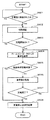
図5は、充電器110の充電制御処理の手順を示すフローチャートである。図5のフローチャートにおいて、充電器110は、充電ガン113が電動車120の充電リッド121に接続されるまで待機する(ステップS501:Noのループ)。充電ガン113が電動車120に接続されたことを接続検知部304によって検知すると(ステップS501:Yes)、充電器110は通信部302によって電動車120との間で通信をおこない、充電が開始可能か否かの初期確認をおこなう(ステップS502)。初期確認によって充電開始可能であると判断されるまでは(ステップS503:No)、ステップS502に戻り、初期確認処理をくり返す。
FIG. 5 is a flowchart showing the procedure of the charging control process of the
充電開始可能であると判断された場合(ステップS503:Yes)、充電器110のロック機構306は、充電ガン113と充電リッド121との間のロックを施錠して(ステップS504)、電力供給部305により電動車120に対して電力供給する(ステップS505)。なお、ロックの施錠(ステップS504)は、充電ガン113が接続された直後や、初期確認(ステップS502)の前におこなってもよい。
When it is determined that charging can be started (step S503: Yes), the
充電器110の充電コントローラ301は、充電中は常時電動車120からの要求(制御信号)を受信し、その内容を確認する(ステップS506)。電動車120から充電停止要求があるまでは(ステップS507:No)、ステップS505に戻り、電力供給部305は、電動車120への電力供給を継続する。電動車120から充電停止要求があると(ステップS507:Yes)、電力供給部305は、電動車120への電力供給を停止する(ステップS508)。そして、充電器110のロック機構306は、充電ガン113と充電リッド121との間のロックを解除して(ステップS509)、本フローチャートによる処理を終了する。
The charging
つづいて、電動車120の充電処理の手順について説明する。
図6は、電動車120の充電処理の手順を示すフローチャートである。図6のフローチャートにおいて、電動車120は、充電リッド121に充電器110の充電ガン113が接続されるまで待機する(ステップS601:Noのループ)。充電リッド121に充電器110の充電ガン113が接続されたことを接続検知部304によって検知すると(ステップS601:Yes)、電動車120の通信部402は充電器110との間で通信をおこない、充電が開始可能か否かの初期確認をおこなう(ステップS602)。初期確認によって充電開始可能であると判断されるまでは(ステップS603:No)、ステップS602に戻り初期確認処理をくり返し、充電開始可能であると判断された場合(ステップS603:Yes)、充電器110の電力供給部305からの電力供給が開始される。
Next, a procedure for charging the
FIG. 6 is a flowchart showing a procedure for charging the
電動車120の車両コントローラ401は、充電中は常時ホームコントローラ210からの要求(制御信号)を受信し、その内容を確認する(ステップS604)。ホームコントローラ210からの要求が緊急制御情報でない場合は(ステップS605:No)、バッテリーの蓄電量を監視して(ステップS606)、充電を完了させるか否かを判断する(ステップS607)。充電を完了させるか否かは、たとえば、バッテリーの蓄電量が目標充電量以上(または蓄電率が目標充電率以上)となったか否かによって判断する。
The
バッテリーの蓄電量が目標充電量以上となるまでは、充電を完了させず(ステップS607:No)、ステップS604に戻り、以降の処理をくり返す。そして、バッテリーの蓄電量が目標充電量以上となり、充電を完了させる場合(ステップS607:Yes)、電動車120の通信部402は、充電器110に対して充電停止要求を送信して(ステップS608)、本フローチャートによる処理を終了する。
Until the charged amount of the battery becomes equal to or greater than the target charge amount, charging is not completed (step S607: No), the process returns to step S604, and the subsequent processing is repeated. When the charged amount of the battery becomes equal to or greater than the target charge amount and charging is completed (step S607: Yes), the
また、ステップS605において、ホームコントローラ210からの要求が緊急制御情報である場合は(ステップS605:Yes)、電動車120の車両コントローラ401は、すぐに充電器110に対して充電停止要求を送信する(ステップS608)。すなわち、電動車120の車両コントローラ401は、充電器110が設置されている地域に対する緊急情報を受信したか否かを判断し(判断手段)、緊急情報を受信したと判断された場合、充電を停止し、ロック手段(ロック機構306,406)のロックを解除する制御信号を出力する。これにより、充電器110の電力供給部305からの電力の供給が停止されるとともに、充電ガン113と充電リッド121との間のロックが解除され、速やかに充電ケーブル112を収納可能したり、電動車120を使用したりすることが可能となる。
In Step S605, when the request from
以上説明したように、充電システム100は、電動車120の充電中はコネクタ(充電ガン113)と給電口(充電リッド121)との間にロックをかけるとともに、充電中に充電器周辺地域を対象とする緊急情報を受信した場合、充電を中止して、充電ガン113と充電リッド121との間にかけられたロックを解除する。これにより、即座に充電ガン113を車両から離脱して、充電ガン113および充電ケーブル112を収納することができる。ユーザは、充電ガン113および充電ケーブル112を収納することによって、確実に充電が終了していることが確認できるとともに、避難時に充電ケーブル112につまずいたり、落下物によって充電ケーブル112が破損したりする危険性を低減することができる。また、ユーザは、必要な場合は、電動車120を使って避難をすることができる。
As described above, the
また、充電システム100は、充電器110または電動車120が家庭内電気機器マネジメントシステム200に接続されているので、充電器110または電動車120の稼働状態や電力消費量を監視したり、遠隔操作や自動制御によって充電器110または電動車120の稼働状態や電力消費量を適切に管理したりすることができる。また、充電システム100は、家庭内電気機器マネジメントシステム200のホームコントローラ210に緊急情報の受信手段が設けられているので、電動車120以外の他の家庭内電気機器211についても緊急情報に対応した制御(たとえば緊急停止など)をおこなうことができる。
In addition, since the
なお、本実施の形態では、ホームコントローラ210からの緊急制御情報を電動車120で受信するものとしたが、充電器110でホームコントローラ210からの緊急制御情報を受信するようにしてもよい。この場合、図5のステップS506を「電動車およびホームコントローラからの要求を確認」と読み替え、緊急制御情報を受信した場合は、直ちにステップS508(電力供給の停止)に移行すればよい。
In the present embodiment, emergency control information from
また、本実施の形態では、ホームコントローラ210を介して緊急情報(緊急制御情報)を受信するものとしたが、これに限らず、電動車120または充電器110が直接緊急情報を受信するようにしてもよい。この場合、電動車120で緊急情報を受信する場合は、図6のステップS604を「緊急情報を確認」、ステップS605を「緊急情報を受信?」と読み替えればよい。また、充電器110で緊急情報を受信する場合は、図5のステップS506を「緊急情報および電動車からの要求を確認」と読み替え、緊急情報を受信した場合は、直ちにステップS508(電力供給の停止)に移行すればよい。このような構成にすれば、充電器110および電動車120が家庭内電気機器マネジメントシステム200に接続されていない場合においても、本発明を適用することができる。また、電動車120に緊急情報の受信手段を設ければ、電動車120を使って移動した移動先や、接続されている充電器に緊急情報の受信手段が設けられていない(スタンドアロン)場合であっても、緊急情報に対応することができる。
In this embodiment, emergency information (emergency control information) is received via the
また、本実施の形態では、車両コントローラ401によって、緊急情報を受信したと判断された場合、車両コントローラ401がロック手段(ロック機構306,406)のロックを解除する制御信号を出力することにより、充電ガン113と充電リッド121との間のロックが解除されるものとしたが、これに限られるものではなく、受信手段で緊急情報を受信した場合に充電ガン113と充電リッド121との間のロックを機械的に解除する解除機構を設け、この解除機構を解除手段としてもよい。例えば、受信手段がホームコントローラ210または充電器110に設けられている場合は、この解除機構を充電ガン113に設けるのが好ましい。また、受信手段が電動車120に設けられている場合は、この解除機構を充電リッド121に設けるのが好ましい。このように、受信手段とより近くなるようにして、充電ガン113または充電リッド121に解除機構を設けることで、緊急時に、充電ガン113と充電リッド121との間のロックをより素早く解除することが可能となる。
In the present embodiment, when the
さらに、本実施の形態では、緊急時には充電ガン113と充電リッド121との間のロックの解除をおこなうものとしたが、ロックの解除に加えて、充電リッド121から充電ガン113を離脱させるようにしてもよい。この場合、充電リッド121および/または充電ガン113に、充電リッド121から充電ガン113を離脱させる力を加える離脱機構(離脱手段)を設ける。充電リッド121から充電ガン113を自動的に離脱させることによって、より迅速に電動車120を乗車可能な状態にすることができ、たとえば、電動車120を用いて避難をする場合などに有効である。
Furthermore, in this embodiment, the lock between the charging
100……充電システム、110……充電器、111……本体部、112……充電ケーブル、113……充電ガン、114……結合部、120……電動車、121……充電リッド、122……蓋、123……結合部、200……家庭内電気機器マネジメントシステム、210……ホームコントローラ、211……電気機器、212……WAN、213……分電盤、301……充電コントローラ、302……通信部、303……ユーザインターフェース、304……接続検知部、305……電力供給部、306……ロック機構、401……車両コントローラ、402……通信部、403……ユーザインターフェース、404……接続検知部、405……バッテリー、406……ロック機構。
DESCRIPTION OF
Claims (4)
前記充電器が設置されている地域に対する緊急情報を受信する受信手段と、
前記受信手段で前記緊急情報を受信した場合、前記充電を停止し、前記ロック手段のロックを解除する解除手段と、
を備えることを特徴とするロック制御装置。 When charging a drive battery mounted on the electric vehicle via a connector and a charging cable connectable to a power supply port of the electric vehicle from a charger installed outside the electric vehicle, the connector and the power supply A lock control device for controlling a locking means for locking a connection with a mouth,
Receiving means for receiving emergency information for the area where the charger is installed;
When the emergency information is received by the receiving means, the charging is stopped, the releasing means for releasing the lock of the locking means,
A lock control device comprising:
Priority Applications (1)
| Application Number | Priority Date | Filing Date | Title |
|---|---|---|---|
| JP2011246308A JP2013106363A (en) | 2011-11-10 | 2011-11-10 | Lock control device |
Applications Claiming Priority (1)
| Application Number | Priority Date | Filing Date | Title |
|---|---|---|---|
| JP2011246308A JP2013106363A (en) | 2011-11-10 | 2011-11-10 | Lock control device |
Publications (1)
| Publication Number | Publication Date |
|---|---|
| JP2013106363A true JP2013106363A (en) | 2013-05-30 |
Family
ID=48625544
Family Applications (1)
| Application Number | Title | Priority Date | Filing Date |
|---|---|---|---|
| JP2011246308A Pending JP2013106363A (en) | 2011-11-10 | 2011-11-10 | Lock control device |
Country Status (1)
| Country | Link |
|---|---|
| JP (1) | JP2013106363A (en) |
Cited By (4)
| Publication number | Priority date | Publication date | Assignee | Title |
|---|---|---|---|---|
| JP2016127606A (en) * | 2014-12-26 | 2016-07-11 | 住友電気工業株式会社 | Charging control device, charging control method, and charging control program |
| CN108270123A (en) * | 2016-12-30 | 2018-07-10 | 郑州宇通客车股份有限公司 | A kind of charging gun locking system for charging equipment |
| US10144298B2 (en) | 2015-04-10 | 2018-12-04 | Toyota Jidosha Kabushiki Kaisha | Power supply device of vehicle |
| CN110936829A (en) * | 2018-09-21 | 2020-03-31 | 株式会社斯巴鲁 | Charging system for vehicle |
Citations (6)
| Publication number | Priority date | Publication date | Assignee | Title |
|---|---|---|---|---|
| JP2002190084A (en) * | 2000-12-21 | 2002-07-05 | Hitachi Commun Syst Inc | Evacuation method at occurrence of disaster |
| JP2005321323A (en) * | 2004-05-10 | 2005-11-17 | Alpine Electronics Inc | Navigation system and route guiding method |
| JP2010226840A (en) * | 2009-03-23 | 2010-10-07 | Toyota Motor Corp | Vehicle and charger |
| WO2010137145A1 (en) * | 2009-05-28 | 2010-12-02 | トヨタ自動車株式会社 | Charging system, and method for controlling vehicle and charging system |
| JP2011172363A (en) * | 2010-02-17 | 2011-09-01 | Toyota Industries Corp | Charge control apparatus, and vehicle charge system |
| JP2011223841A (en) * | 2010-04-14 | 2011-11-04 | Sharp Corp | Power supply system and network system |
-
2011
- 2011-11-10 JP JP2011246308A patent/JP2013106363A/en active Pending
Patent Citations (6)
| Publication number | Priority date | Publication date | Assignee | Title |
|---|---|---|---|---|
| JP2002190084A (en) * | 2000-12-21 | 2002-07-05 | Hitachi Commun Syst Inc | Evacuation method at occurrence of disaster |
| JP2005321323A (en) * | 2004-05-10 | 2005-11-17 | Alpine Electronics Inc | Navigation system and route guiding method |
| JP2010226840A (en) * | 2009-03-23 | 2010-10-07 | Toyota Motor Corp | Vehicle and charger |
| WO2010137145A1 (en) * | 2009-05-28 | 2010-12-02 | トヨタ自動車株式会社 | Charging system, and method for controlling vehicle and charging system |
| JP2011172363A (en) * | 2010-02-17 | 2011-09-01 | Toyota Industries Corp | Charge control apparatus, and vehicle charge system |
| JP2011223841A (en) * | 2010-04-14 | 2011-11-04 | Sharp Corp | Power supply system and network system |
Cited By (4)
| Publication number | Priority date | Publication date | Assignee | Title |
|---|---|---|---|---|
| JP2016127606A (en) * | 2014-12-26 | 2016-07-11 | 住友電気工業株式会社 | Charging control device, charging control method, and charging control program |
| US10144298B2 (en) | 2015-04-10 | 2018-12-04 | Toyota Jidosha Kabushiki Kaisha | Power supply device of vehicle |
| CN108270123A (en) * | 2016-12-30 | 2018-07-10 | 郑州宇通客车股份有限公司 | A kind of charging gun locking system for charging equipment |
| CN110936829A (en) * | 2018-09-21 | 2020-03-31 | 株式会社斯巴鲁 | Charging system for vehicle |
Similar Documents
| Publication | Publication Date | Title |
|---|---|---|
| EP2556986B1 (en) | Vehicle charging stations and methods for use in charging an electrically powered vehicle | |
| JP5383862B2 (en) | Power monitoring system and electric vehicle | |
| US20130041850A1 (en) | Electrically powered vehicles and methods for use in charging an electrically powered vehicle | |
| CN105235544B (en) | Power-on and power-off control system and method for battery-replaceable electric automobile | |
| US20130041531A1 (en) | Vehicle controllers and methods for use in charging an electrically powered vehicle | |
| US20190280498A1 (en) | Charging system | |
| JP5853931B2 (en) | Energy management device | |
| JP2013106363A (en) | Lock control device | |
| JP5693776B2 (en) | Charge / discharge device | |
| EP3065255B1 (en) | Power conversion system and connector | |
| JP2015228279A (en) | Power control unit | |
| JP2018129154A (en) | Charger/discharger and charging/discharging system | |
| WO2017149638A1 (en) | Charge/discharge device | |
| CN109873496B (en) | Cable for high-voltage charge control and cable system for high-voltage charge control | |
| JP6504101B2 (en) | Power controller | |
| JP2011101531A (en) | Distribution system for building and method of protecting trunk line in the same | |
| JP6505351B1 (en) | Charger | |
| JP5815895B2 (en) | Charge / discharge device | |
| CN208232851U (en) | A kind of cell managing device | |
| CN110843564A (en) | Intelligent charging and battery replacing system for electric vehicle | |
| JP2018064431A (en) | Power control unit | |
| WO2016059897A1 (en) | Power control device | |
| EP3929126B1 (en) | Method of replacing a battery and an elevator system | |
| JP6095746B2 (en) | Charge / discharge device | |
| KR20130138586A (en) | Electric vehicle charge system ane charging method of the same, and electric vehicle charge controller |
Legal Events
| Date | Code | Title | Description |
|---|---|---|---|
| A621 | Written request for application examination |
Free format text: JAPANESE INTERMEDIATE CODE: A621 Effective date: 20140418 |
|
| A977 | Report on retrieval |
Free format text: JAPANESE INTERMEDIATE CODE: A971007 Effective date: 20141203 |
|
| A131 | Notification of reasons for refusal |
Free format text: JAPANESE INTERMEDIATE CODE: A131 Effective date: 20141209 |
|
| A02 | Decision of refusal |
Free format text: JAPANESE INTERMEDIATE CODE: A02 Effective date: 20150407 |