EP2434478B1 - Benachrichtigungssteuerung einer Tonstilerzeugung für ein Blasinstrument mit Mundstück - Google Patents
Benachrichtigungssteuerung einer Tonstilerzeugung für ein Blasinstrument mit Mundstück Download PDFInfo
- Publication number
- EP2434478B1 EP2434478B1 EP11182895.0A EP11182895A EP2434478B1 EP 2434478 B1 EP2434478 B1 EP 2434478B1 EP 11182895 A EP11182895 A EP 11182895A EP 2434478 B1 EP2434478 B1 EP 2434478B1
- Authority
- EP
- European Patent Office
- Prior art keywords
- tone
- section
- pitch
- mouthpiece
- human player
- Prior art date
- Legal status (The legal status is an assumption and is not a legal conclusion. Google has not performed a legal analysis and makes no representation as to the accuracy of the status listed.)
- Not-in-force
Links
- 239000011295 pitch Substances 0.000 claims description 178
- 238000000034 method Methods 0.000 claims description 10
- 238000001514 detection method Methods 0.000 claims description 9
- 230000000994 depressogenic effect Effects 0.000 description 12
- 238000010586 diagram Methods 0.000 description 12
- 230000003321 amplification Effects 0.000 description 11
- 238000003199 nucleic acid amplification method Methods 0.000 description 11
- 238000006243 chemical reaction Methods 0.000 description 9
- 238000010276 construction Methods 0.000 description 9
- 238000012986 modification Methods 0.000 description 8
- 230000004048 modification Effects 0.000 description 8
- 230000000881 depressing effect Effects 0.000 description 7
- 230000006835 compression Effects 0.000 description 6
- 238000007906 compression Methods 0.000 description 6
- 230000004044 response Effects 0.000 description 6
- 230000006399 behavior Effects 0.000 description 4
- 230000007423 decrease Effects 0.000 description 4
- 238000012545 processing Methods 0.000 description 4
- 239000003086 colorant Substances 0.000 description 3
- 235000014676 Phragmites communis Nutrition 0.000 description 2
- 238000013459 approach Methods 0.000 description 2
- 238000007664 blowing Methods 0.000 description 2
- 230000006870 function Effects 0.000 description 2
- 230000002093 peripheral effect Effects 0.000 description 2
- 229910001369 Brass Inorganic materials 0.000 description 1
- 230000001174 ascending effect Effects 0.000 description 1
- 230000004397 blinking Effects 0.000 description 1
- 239000010951 brass Substances 0.000 description 1
- 238000004891 communication Methods 0.000 description 1
- 238000006073 displacement reaction Methods 0.000 description 1
Images


Classifications
-
- G—PHYSICS
- G10—MUSICAL INSTRUMENTS; ACOUSTICS
- G10H—ELECTROPHONIC MUSICAL INSTRUMENTS; INSTRUMENTS IN WHICH THE TONES ARE GENERATED BY ELECTROMECHANICAL MEANS OR ELECTRONIC GENERATORS, OR IN WHICH THE TONES ARE SYNTHESISED FROM A DATA STORE
- G10H1/00—Details of electrophonic musical instruments
- G10H1/0008—Associated control or indicating means
-
- G—PHYSICS
- G10—MUSICAL INSTRUMENTS; ACOUSTICS
- G10H—ELECTROPHONIC MUSICAL INSTRUMENTS; INSTRUMENTS IN WHICH THE TONES ARE GENERATED BY ELECTROMECHANICAL MEANS OR ELECTRONIC GENERATORS, OR IN WHICH THE TONES ARE SYNTHESISED FROM A DATA STORE
- G10H1/00—Details of electrophonic musical instruments
- G10H1/32—Constructional details
-
- G—PHYSICS
- G10—MUSICAL INSTRUMENTS; ACOUSTICS
- G10H—ELECTROPHONIC MUSICAL INSTRUMENTS; INSTRUMENTS IN WHICH THE TONES ARE GENERATED BY ELECTROMECHANICAL MEANS OR ELECTRONIC GENERATORS, OR IN WHICH THE TONES ARE SYNTHESISED FROM A DATA STORE
- G10H3/00—Instruments in which the tones are generated by electromechanical means
- G10H3/12—Instruments in which the tones are generated by electromechanical means using mechanical resonant generators, e.g. strings or percussive instruments, the tones of which are picked up by electromechanical transducers, the electrical signals being further manipulated or amplified and subsequently converted to sound by a loudspeaker or equivalent instrument
- G10H3/24—Instruments in which the tones are generated by electromechanical means using mechanical resonant generators, e.g. strings or percussive instruments, the tones of which are picked up by electromechanical transducers, the electrical signals being further manipulated or amplified and subsequently converted to sound by a loudspeaker or equivalent instrument incorporating feedback means, e.g. acoustic
- G10H3/26—Instruments in which the tones are generated by electromechanical means using mechanical resonant generators, e.g. strings or percussive instruments, the tones of which are picked up by electromechanical transducers, the electrical signals being further manipulated or amplified and subsequently converted to sound by a loudspeaker or equivalent instrument incorporating feedback means, e.g. acoustic using electric feedback
-
- G—PHYSICS
- G10—MUSICAL INSTRUMENTS; ACOUSTICS
- G10H—ELECTROPHONIC MUSICAL INSTRUMENTS; INSTRUMENTS IN WHICH THE TONES ARE GENERATED BY ELECTROMECHANICAL MEANS OR ELECTRONIC GENERATORS, OR IN WHICH THE TONES ARE SYNTHESISED FROM A DATA STORE
- G10H2220/00—Input/output interfacing specifically adapted for electrophonic musical tools or instruments
- G10H2220/005—Non-interactive screen display of musical or status data
-
- G—PHYSICS
- G10—MUSICAL INSTRUMENTS; ACOUSTICS
- G10H—ELECTROPHONIC MUSICAL INSTRUMENTS; INSTRUMENTS IN WHICH THE TONES ARE GENERATED BY ELECTROMECHANICAL MEANS OR ELECTRONIC GENERATORS, OR IN WHICH THE TONES ARE SYNTHESISED FROM A DATA STORE
- G10H2220/00—Input/output interfacing specifically adapted for electrophonic musical tools or instruments
- G10H2220/155—User input interfaces for electrophonic musical instruments
- G10H2220/361—Mouth control in general, i.e. breath, mouth, teeth, tongue or lip-controlled input devices or sensors detecting, e.g. lip position, lip vibration, air pressure, air velocity, air flow or air jet angle
-
- G—PHYSICS
- G10—MUSICAL INSTRUMENTS; ACOUSTICS
- G10H—ELECTROPHONIC MUSICAL INSTRUMENTS; INSTRUMENTS IN WHICH THE TONES ARE GENERATED BY ELECTROMECHANICAL MEANS OR ELECTRONIC GENERATORS, OR IN WHICH THE TONES ARE SYNTHESISED FROM A DATA STORE
- G10H2230/00—General physical, ergonomic or hardware implementation of electrophonic musical tools or instruments, e.g. shape or architecture
- G10H2230/045—Special instrument [spint], i.e. mimicking the ergonomy, shape, sound or other characteristic of a specific acoustic musical instrument category
- G10H2230/155—Spint wind instrument, i.e. mimicking musical wind instrument features; Electrophonic aspects of acoustic wind instruments; MIDI-like control therefor
- G10H2230/171—Spint brass mouthpiece, i.e. mimicking brass-like instruments equipped with a cupped mouthpiece, e.g. allowing it to be played like a brass instrument, with lip controlled sound generation as in an acoustic brass instrument; Embouchure sensor or MIDI interfaces therefor
- G10H2230/175—Spint trumpet, i.e. mimicking cylindrical bore brass instruments, e.g. bugle
Definitions
- the present invention relates to tone generating style notification control for wind instruments having a mouthpiece section.
- patent literature 1 discloses an electronic wind instrument which simulates performance operation and tone color (timbre) of a wind instrument.
- the electronic wind instrument disclosed in patent literature 1 includes a mouthpiece section, and, in response to a human player performing, with a finger, operation for designating a tone color and pitch within an octave pitch range, the electronic wind instrument generates a tone corresponding to the designated tone color and pitch.
- 2010-48909 discloses an audio processing apparatus which outputs a tone of a wind instrument based on an octave corresponding to an angle at which a body device has been inclined by a human player and a note name corresponding to depressing operation performed by the human player.
- harmonics responsive to human player's piston operation are sounded while resonating in accordance with a state of human player's lips applied to the mouthpiece.
- a performance feeling felt by the human player is completely different from an actual performance feeling (i.e., performance feeling felt by a human player when performing an acoustic or natural wind instrument).
- EP 1 748 416 A1 specifically a tone control device applied to an electronic wind instrument which realizes an octave-changeover-blowing technique in which the same note is produced with different octaves respectively by use of the same fingering state, thus increasing controllable ranges with regard to the tone volume, tone color, and tone pitch.
- a plurality of flow sensors are arranged in proximity to an edge with which a jet flow caused by blowing air into a blow hole of a lip plate collides within a tube of a wind instrument controller simulating an air-reed instrument.
- the flow sensors are horizontally arranged to detect a jet width, thus controlling the tone volume, and the flow sensors are vertically arranged to detect a jet eccentricity or a jet thickness, thus controlling the tone color. Ascending or descending of the tone pitch by octaves is controlled by use of the flow sensor and a jet length sensor.
- the tone control device uses a pitch table, in which a horizontal axis represents a lip contact value, and a vertical axis represents pitch variations.
- the table is produced by defining a standard state realizing an intermediate lip contact value, so that as the lip contact value decreases from the standard state, pitch variations increase, while as the lip contact value increases from the standard state, pitch variations decrease.
- an improved tone generating style notification control apparatus for a musical instrument described herein which has a mouthpiece section, the mouthpiece section being operable with a mouth of a human player, which comprises: a detector which detects a physical amount caused by operation performed on the mouthpiece section with the mouth of the human player; a storage section which stores therein information defining relationship between various values or ranges of the physical amount and tone pitches; an identification section which, by referencing the storage section, identifies a tone pitch corresponding to the physical amount detected via the detector; and a notification section which notifies the human player of an expected tone generating style on the basis of the tone pitch identified by the identification section, the expected tone generating style being a style of a tone expected to be generated by the musical instrument in response to the operation performed on the mouthpiece section with the mouth of the human player.
- This improved tone generating style notification control apparatus allows the human player to ascertain, on the basis of the expected tone generating style notified by the notification section, what tone pitch the operation performed on the mouthpiece section with the mouth of the human player corresponds to, and thus, feedback to the human player can be made effectively to thereby allow the human player to appropriately operate the mouthpiece section for achieving a desired tone pitch.
- the present invention provides an improved tone generating style notification control apparatus for a musical instrument having a mouthpiece section, the mouthpiece section being operable with a mouth of a human player, which comprises: a detector arranged to detect a physical amount caused by operation performed on the mouthpiece section with the mouth of the human player; a first storage section arranged to store therein a tone pitch table defining a relationship between various ranges of the physical amount and tone pitches; a second storage section arranged to store therein a gain table defining, as gain information, values corresponding to deviations of the physical amount from a predetermined reference point, for each tone pitch and within the range of the physical amount corresponding to the tone pitch; an identification section which is arranged to identify, with regard to the physical amount detected by the detector, a tone pitch by referencing the tone pitch table, and to identify gain information by referencing the gain table; and a notification section arranged to notify the human player of the tone pitch and the gain information identified by the identification section.
- the human player can ascertain, on the basis of the notification by the notification section, what tone pitch and gain the operation performed on the mouthpiece section with the mouth of the human player corresponds to, and thus, feedback to the human player can be made effectively to thereby allow the human player to appropriately operate the mouthpiece section for achieving a desired tone pitch and gain.
- the human player can, for example, cause a desired tone to be generated by operating the mouthpiece section with its (his or her) mouth as if he were playing a natural wind instrument.
- the present invention allows the human player to ascertain, on the basis of the notified gain information, a degree of resonance corresponding to the operation performed on the mouthpiece section.
- an improved musical instrument which comprises: the aforementioned tone generating style notification control apparatus; the mouthpiece section; an operation section operable with a finger of a human player; a tone generation mechanism arranged to generate a tone on the basis of a combination of operation performed on the mouthpiece section with a mouth of the human player and operation performed on said operation section with the finger of the human player.
- the present invention may be constructed and implemented not only as the apparatus invention as discussed above but also as a method invention. Also, the present invention may be arranged and implemented as a software program for execution by a processor such as a computer or DSP, as well as a storage medium storing such a software program.
- a tone generating style notification control of the present invention is suited for application to musical instruments and particularly suited for use in electronic wind instruments, and background examples and embodiments of the tone generating style notification control apparatus of the present invention will hereinafter be described as used in a trumpet-type electronic wind instrument.
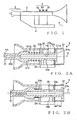
- Fig. 1 is a view showing an outer appearance of the electronic wind instrument 1 employing the tone generating style notification control apparatus of the present background example.
- the electronic wind instrument 1 includes a body casing (body section of the instrument 1) 2 simulating a shape of an acoustic or natural trumpet, a mouthpiece unit 3 through which a human player (or user) blows breath into the instrument 1, and a piston operation section (operation section) 4 and a display section 5 provided on the body casing 2.
- the display section 5 is provided at such a position where the human player playing the wind instrument 1 can easily view the display section 5.
- the piston operation section 4 includes three pistons, i.e. first piston 4a, second piston 4b and third piston 4c.
- Each of the pistons 4a to 4c is constructed to be depressed by a human player's finger into the body casing 2, and each of the pistons 4a to 4c is provided with a switch (detector or detection section) for detecting whether or not the piston in question has been depressed into the body casing 2 by the human player.
- a switch detector or detection section
- Figs. 2A and 2B are sectional views showing the interior of the mouthpiece unit 3 employed in the instant embodiment.
- the mouthpiece unit 3 includes a mouthpiece section 31 in the form of a cylindrical member (cylinder) having a diameter increasing in a rightward direction of Fig. 2A , and a mouthpiece casing 32 in the form of a cylindrical member having a diameter increasing in a leftward direction of Fig. 2A .
- the mouthpiece section 31 and the mouthpiece casing 32 are disposed concentrically about a center axis A.
- the mouthpiece section 31 includes a small-diameter portion 310 to be held in the human player's mouth (or between the lips of the human player), and a large-diameter portion 311 greater in diameter than the small-diameter portion 310.
- the large-diameter portion 311 of the mouthpiece section 31 has an annular recessed portion 31b formed in the outer periphery thereof.
- An end surface 311b of the annular recessed portion 31b closer to the small-diameter portion 310 supports one end of a coil-shaped compression spring 33 wound around the outer periphery of the annular recessed portion 31b.
- An annular portion of the large-diameter portion 311 defining the other end surface 311a of the recessed portion 31b is provided as a stopper portion (flange) 31a.
- the mouthpiece section 31 has a central hole H1 formed therein to extend axially through the mouthpiece section 31 from the small-diameter portion 310 to the stopper portion 31a of the large-diameter portion 311.
- the large-diameter portion 311 has a hole H2 formed in the recessed portion 31b and radially extending through an upper region (i.e., upper region in Fig. 2A ) of the recessed portion 31b, and a pressure sensor 35 is inserted in the hole H2.
- the large-diameter portion 311 also has a cavity (not shown with a reference numeral) in a lower region (i.e., lower region in Fig. 2A ) of the recessed portion 31b opposite to the hole H2.
- the pressure sensor 35 moves along the center axis A as the mouthpiece section 31 is moved or displaced along the axis A, to detect pressure variation in the hole H1 formed in the mouthpiece section 31 and thereby detect pressure of breath blown by the human player via the small-diameter portion 310 of the mouthpiece section 31.
- breath pressure Such pressure of breath blown by the human player via the small-diameter portion 3 10 of the mouthpiece section 31 will hereinafter be referred to also as "breath pressure”.
- the mouthpiece casing 32 includes two ring-shaped or annular projecting members 32a and 32b that project inwardly from an inner wall portion of the mouthpiece casing 32 toward and short of the center axis A and that are spaced from each other by a predetermined distance along the center axis A.
- the annular projecting member 32b supports the other end of the compression spring 33; namely, the compression spring 33 is provided between, and fixed at its opposite ends to, the end surface 311b of the annular recessed portion 31b and the annular projecting member 32b.
- the mouthpiece section 31 is axially movably supported at its outer peripheral surface by the inner peripheral surfaces of the annular projecting members 32a and 32b; namely, the mouthpiece section 31 is movable or displaceable in parallel to the center axis A while being supported by the annular projecting members 32a and 32b.
- a sliding volume control 34 which is a detector or detection section for detecting a physical amount caused by human player's operation on the mouthpiece section 31, is provided on a lower portion (i.e., lower portion in Fig. 2A ) of the mouthpiece casing 32, and a sliding portion 34a movable along the center axis A as the mouthpiece section 31 is moved or displaced along the center axis A is inserted in the cavity (not shown with a reference numeral) opposite to the hole H2.
- a resistance value varying continuously (or at least in a multistep fashion) in response to the movement of the sliding portion 34a corresponds to an (axial) operational position of the mouthpiece section 31.
- the mouthpiece section 31 When no force is being applied to the mouthpiece section 31 in a direction toward the rear end of the mouthpiece casing 32 opposite from the front end of the mouthpiece casing 32 that is closer to the human player, the mouthpiece section 31 is held stationary by the compression spring 33 at a position where the stopper 31a and the projecting member 32a of the mouthpiece casing 32 abuttingly contact each other, as shown in Fig. 2A .
- the compression spring 33 is compressed by the applied force, in response to which the mouthpiece section 31 moves toward the rear end of the casing 32 in parallel to the center axis A and the stopper 31a and the annular projecting member 32a of the mouthpiece casing 32 axially move away from each other.
- a limit of the movement of the mouthpiece section 31 toward the rear end of the mouthpiece casing 32 is at a position where the compression spring 33 is compressed to the greatest extent as shown in Fig. 2B and where the stopper 31a and the mouthpiece casing 32 are spaced from each other by a distance L.
- the interior construction of the mouthpiece unit 3 is not necessarily limited to the foregoing as long as the mouthpiece casing 32 and the mouthpiece section 31 are slidable relative to each other and arrangements are made for detecting, at least in a multistep fashion, an operational position of the mouthpiece section 31 and pressure of breath blown into the mouthpiece section 31.
- the following describe a construction for the electronic wind instrument 1 to perform tone generation processing.
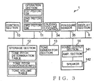
- Fig. 3 is a block diagram showing an example construction of electronic circuitry for use in the tone generation processing by the electronic wind instrument 1.
- the electronic wind instrument 1 includes, on the body casing 2, a control section 10, an operation section 11, a storage section 12, a tone generator section 13, a sound output section 14, and the above-mentioned sliding volume control 34, pressure sensor 35 and display section 5.
- the control section 10 includes a CPU (Central Processing Unit), and a memory comprising a ROM (Read-Only Memory) and a RAM (Random Access Memory). By executing control programs stored in the ROM, the control section 10 controls various components connected to the control section 10.
- a CPU Central Processing Unit
- ROM Read-Only Memory
- RAM Random Access Memory
- control section 10 not only identifies, as notification information, a tone pitch soundable at a moved-to position (i.e., current operating position) of the mouthpiece section 31 and causes the display section 5 to visually display a tone generating style based on the identified notification information, but also identifies tone generation instructing information indicative of a tone pitch corresponding to an operational state of the piston operation section 4 and an operational position of the mouthpiece section 31 and performs control to audibly generate a tone based on the tone generation instructing information and with a tone volume level corresponding to an intensity of breath blown by the human player into the mouthpiece section 31.
- the operation section 11 includes a switch for turning on or off (i.e., switching between ON and OFF states of) a power supply (not shown) to the electronic wind instrument 1, and a first piston switch (SW), second piston switch and third piston switch corresponding to the first piston 4a, second piston 4b and third piston 4c, respectively, of the piston control section 4.
- each of the piston switches outputs an ON/OFF signal indicative of whether or not the corresponding piston is currently in a depressed position.
- an operation detection section for detecting an operational state of the piston operation section 4 may be in the form of a multistep switch or a continuous amount sensor.
- the display section 5 is a display device in the form of LEDs, LCD and/or the like, which displays a tone generating style under control of the control section 10.
- the sliding volume control 34 is an example of a detection section for detecting a physical amount caused by operation performed on the mouthpiece section 31 with the human player's mouth. In the present example, the sliding volume control 34 detects an operational position of the mouthpiece section 31 having been moved by the human player (i.e., moved-to position of the mouthpiece section 31) and sends a result of the mouthpiece section position detection to the control section 10.
- the pressure sensor 35 is an example of a breath pressure detection section for detecting pressure of breath blown by the human player into the mouthpiece section 31, which detects pressure variation within the mouthpiece section 31 and sends a result of the pressure detection to the control section 10.
- the storage section 12 which is in the form of a non-volatile storage medium, stores therein various data, such as a tone pitch determination table 110 and tone pitch conversion information 120 that are examples of tone pitch information shown in Fig. 4 , a tone volume table 130 shown in Fig. 5 , and the like. Details of the tone pitch determination table 110, tone pitch conversion information 120 and tone volume table 130 will be discussed later.
- the tone generator section 13, which is for example a tone generator based on the MIDI (Musical Instrument Digital Interface) standards, generates a tone signal of a tone pitch instructed on the basis of instruction information given from the control section 10 and of a separately-selected musical instrument tone color, such as a trumpet tone color, and then sends the thus-generated tone signal to the sound output section 14.
- the sound output section 14 includes an amplification section 141 for amplifying the tone signal, input from the tone generator section 13, in accordance with an instruction from the control section 10, and a speaker 142 for audibly reproducing or sounding the amplified tone signal.
- the tone generator section 13 and the sound output section 14 together constitute an electronic tone generation mechanism.
- Fig. 4A shows an example of the tone pitch determination table 110.
- the tone pitch determination table 110 as shown in Fig. 4A , there are defined threshold values (V11, V21, ...) of individual harmonics corresponding to various fingerings, and tone pitches (C3, G3, ...) corresponding to various positions of the mouthpiece section 31.
- positions located more rightward in a direction of a rightward arrow represent operational positions of the mouthpiece section 31 depressed deeper into the mouthpiece unit 3, and the fingerings represent depressing operation of the first piston 4a, second piston 4b and third piston 4c.
- fingering "1” indicates depressing operation on the first piston 4a
- fingering "2” indicates depressing operation on the second piston 4b
- fingering "3” indicates depressing operation on the third piston 4c.
- fingering "0” indicates a state where all of the pistons are in the non-depressed, open position
- fingering "1 ⁇ 2” indicates operation in which the first and second pistons 4a and 4b are depressed simultaneously
- fingering "2 ⁇ 3” indicates operation in which the second and third pistons 4b and 4c are depressed simultaneously
- fingering "1 ⁇ 3” indicates operation in which the first and third pistons 4a and 4c are depressed simultaneously
- fingering "1 ⁇ 2 ⁇ 3" indicates operation in which all of the pistons 4a, 4b and 4c are depressed simultaneously.
- Each of the harmonics predetermined per fingering indicates what integer multiple of a fundamental vibrational mode of air column resonance corresponding to the fingering a vibration mode in question is.
- Threshold values of positions of the mouthpiece section 31 are preset in relation to each harmonics row where the order of harmonic sequentially increases like "2, 3, 4, 5, " from the left end of the row corresponding to the fingering.
- threshold values of the harmonics row when the fingering is "1" are identified as smaller than V13 for the second-order harmonic, as equal to or greater than V13 but smaller than V23 for the third-order harmonic, as equal to or greater than V23 but smaller than V33 for the fourth-order harmonic, and so on.
- the threshold values of the harmonics row corresponding to the current fingering operation are identified, and a tone pitch to be sounded is identified in accordance with the threshold values and current operational position of the mouthpiece section 31.
- tone pitch "F3" is identified as the tone pitch to be sounded.
- Fig. 4B shows an example of the tone pitch conversion information 120.
- the tone pitch conversion information 120 predefines individual tone pitches, corresponding to various operational positions of the mouthpiece section 31, on the basis of a predefined mathematical expression or table indicated by a straight line 121 of Fig. 4B.
- Fig. 4C shows correspondency relationship between the positions indicated by the tone pitch conversion information 120 and the tone pitches indicated by the tone pitch determination table 110 of Fig. 4A .
- the positions of the mouthpiece section 3 land the tone pitches are associated with each other in one-to-one relationship such that every adjoining tone pitches are spaced from each other by a positional interval ⁇ V.
- the pitch corresponding to the operational position of the mouthpiece section 31 is identified on the basis of the tone pitch conversion information 120.
- Fig. 5 shows an example format and example data of the tone volume table 130.
- breath pressure levels and tone volume levels are prestored in association with each other.
- "Breath Pressure” indicates a range of breath pressure levels corresponding to an output value of the pressure sensor 35
- "Tone Volume Level” indicates a tone volume level with which a tone signal is to be output in the corresponding range of breath pressure levels (in the illustrated example of Fig. 5 , P1 ⁇ P2 ⁇ P3 ⁇ P4 ..., and level 1 ⁇ level 2 ⁇ level 3 ).
- Fig. 6 is a flow chart of an example operational sequence of the electronic wind instrument 1.
- the control section 10 identifies, as notification information, a tone pitch corresponding to the operational position of the mouthpiece section 31, detected at step S11, by referencing the tone pitch conversion information 120 stored in the storage section 12, and displays an expected tone generating style corresponding to the identified tone pitch, at step S12.
- the expected tone generating style is a style of a tone expected to be generated by the electronic wind instrument 1 in response to human player's operation on the mouthpiece section 31 with its (his or her) mouth, e.g., a tone pitch expected to be sounded in response to the human player's operation on the mouthpiece section 31.
- tone pitch "C3” For example, if the detected current operational position of the mouthpiece section 31, having been depressed by the human player, corresponds to tone pitch "C3", then an indicator indicating tone pitch "C3", corresponding to the current operational position of the mouthpiece section 31, in such a manner that tone pitch "C3" is distinguishable from the other tone pitches is displayed on the display section 5 as the tone generating style.
- the human player can confirm that the current operational position of the mouthpiece section 31 having been depressed thereby is in a harmonics state corresponding to tone pitch "C3". Then, the human player determines whether the tone corresponding to the current operational position of the mouthpiece section 31 coincides with its (his or her) desired tone, and, if not, the human player moves or adjusts the operational position of the mouthpiece section 31 so as to approach the desired tone.
- the control section 10 reverts to step S12, where it identifies a tone pitch corresponding to the moved-to position on the basis of the tone pitch conversion information 120 and displays, on the display section 5, a tone generating style indicative of the identified tone pitch.
- the control section 10 detects human player's operation on the piston operation section 4 at step S 14, identifies threshold values of a harmonics row corresponding to the fingering represented by the human player's operation on the piston operation section 4, and identifies, as tone generation instructing information, a pitch corresponding to the operational position of the mouthpiece section 31 detected at step S11, at step S 15. If, in the illustrated example of Fig.
- the current operational position of the mouthpiece section 31 corresponds to a position corresponding to tone pitch "F3" (i.e., the mouthpiece section 31 is currently at the position corresponding to tone pitch "F3") and the operation of the piston operation section 4 represents fingering "1" (where the first piston is “ON” and the second and third pistons are “OFF”)
- the mouthpiece section 31 is located within the threshold value range of the third-order harmonic corresponding to fingering "1" in the tone pitch determination table 110, and thus, tone pitch "F3" is identified as a tone pitch to be sounded.
- tone pitch "G3" is identified as a tone pitch to be sounded, because, in this case, the mouthpiece section 31 is located within the threshold value range of the third-order harmonic corresponding to fingering "0" in the tone pitch determination table 110.
- the control section 10 detects, by means of the pressure sensor 35, the breath blown into the hole H1 by the human player. If the thus-detected breath pressure is equal to or over a predetermined threshold value (YES determination at step S16), the control section 10 references the tone volume table 130, stored in the storage section 12, to identify a tone volume level corresponding to the detected breath pressure, so that it instructs or indicates the identified tone volume level to the sound output section 14 and sends the tone generation instructing information, identified at step S 15, to the tone generator section 13 (step S17).
- the tone generator section 13 generates a tone signal of a tone pitch based on the tone generation instructing information sent from the control section 10 and outputs the thus-generated tone signal to the sound output section 14, where the amplification section 141 amplifies the tone signal, output from the tone generator section 13, in accordance with the tone volume level indicated or instructed by the control section 10 so that the amplified signal is audibly output or generated via the speaker 142 (step S18).
- control section 10 performs control to not generate a tone of the identified tone pitch and repeats the operations at and after step S11.
- the above-described background example allows the human player to confirm whether or not the mouthpiece section 31 is currently at a position corresponding to the desired tone.
- the desired tone can be generated reliably by the human player performing piston operation on the piston operation section 4 with the mouthpiece section 31 fixed at the operational position corresponding to the desired tone.
- Fig. 8 is a view showing an example outer appearance of the electronic wind instrument la employing the embodiment of the tone generating style notification control apparatus of the present invention.
- the electronic wind instrument 1a is different from the above-described electronic wind instrument 1 employing the background example tone generating style notification control apparatus in that it includes a vibrating section 6 provided on the mouthpiece section 31 of the mouthpiece unit 3. More specifically, the electronic wind instrument 1a employing the embodiment is different from the electronic wind instrument 1 of the background example in that the vibrating section 6 is provided in place of the display section 5, and in that the storage section 12 has a tone pitch/gain determination table and vibrating pattern information stored therein, as shown in Fig. 9 .
- the vibrating section 6 includes a vibrator that transmits to the outside a vibration signal as mechanical vibration, and, under control of the control section 10, the vibrating section 6 generates a vibration signal corresponding to an instructed frequency, and adjusts the vibration signal in accordance with an instructed gain so that the vibrator of the vibrating section 6 is caused to vibrate in accordance with the adjusted vibration signal.
- the vibrator in the embodiment will be described below as an electromagnetic vibrator
- the vibrator may be in the form of a so-called vibrating motor that rotates an eccentric weight.
- the storage section 12 stores therein a tone volume table 130 similar to that provided in the background example, the tone pitch/gain determination table 220 and the vibrating pattern information 230 shown in Fig. 11 .
- the sound output section 14 includes a first amplification section 141 having a similar function to the amplification section 141 provided in the background example, the speaker 142 for audibly reproducing or sounding a tone signal, and a second amplification section 143 for adjusting the tone signal, amplified by the first amplification section 141, in accordance with a gain instructed by the control section 10 and outputting the thus-adjusted tone signal to the speaker 142.
- the tone pitch/gain determination table 220 shown in Fig. 10 is a table predefining, for each of various operational states of the piston operation section 4, a gain value (vertical axis of the table) corresponding to an amount of movement or displacement (horizontal axis of the table) of the mouthpiece section 31. More specifically, tone pitches corresponding to individual fingerings and ranges of movement (i.e., movement ranges) of the mouthpiece section 31 corresponding to individual tone pitches are predefined as the tone pitch table, and gain information indicated by straight lines G and corresponding to positions of the mouthpiece section 31 is preset per tone pitch as the gain table. As the gain information, gains of the sound output section 14 and vibration section 6 are each set at 100% (as indicated by an upper horizontal solid line G1 in Fig.
- the mouthpiece section 31 when the mouthpiece section 31 is at a predetermined position (hereinafter referred to "reference point" in the movement range movement corresponding to any one of the tone pitches. Further, when the mouthpiece section 31 is not at the reference point in the range of movement corresponding to any one of the tone pitches, the sound output section 14 and vibration section 6 are each set at a gain ratio corresponding to a distance or deviation from the reference point. For example, as indicated by oblique straight lines G in Fig. 10 for fingering "2", X1, X2, X3, ... indicating substantial midpoints of the movement ranges corresponding to the tone pitches are the reference points corresponding to the tone pitches.
- the gain information is defined in such a manner that the gain when the mouthpiece section 31 is at each of these midpoints is set at 100 %, and the gain decreases at a predetermined rate toward a minimum gain value of 20 % (as indicated by a lower horizontal solid line G2 in Fig. 10 ) as the mouthpiece section 31 deviates away from the reference point.
- the tone volume and vibration of the vibrator of the vibrating section 6 is maximized when the mouthpiece section 31 is at the reference point, and the tone volume and vibration of the vibrator becomes smaller as the mouthpiece section 31 deviates from the reference point.
- the reference point of each tone pitch is made a position where a tone of that pitch resonates most, so that the human player can recognize variation in resonance corresponding to individual operational positions of the mouthpiece section 31.
- variation in resonance is notified to the human player by the tone volume and mechanical vibration of the vibrator being varied depending on how deep the mouthpiece section 31 is depressed into the mouthpiece casing 32.
- Fig. 11 shows an example of the vibrating pattern information 230 employed in the embodiment.
- the vibrating pattern information 230 defines a frequency with which to vibrate the vibrating section 6 (more specifically, vibrator) in accordance with a frequency of a tone pitch to be sounded.
- frequencies 160 - 1,800 Hz of tones playable by the trumpet are shown on the horizontal axis as frequencies of tone pitches (tone generating frequencies), and vibrator vibrating frequencies corresponding to the frequencies of tone pitches (tone generating frequencies) are set as 10 - 200 Hz on the vertical axis.
- vibration of the vibrating frequency corresponding to the tone pitch is controlled in level in accordance with a gain.
- the vibrating frequency of the vibrating section 6 may be controlled in accordance with a gain, in which case vibrating pattern information 231 defining vibrating frequencies (10 - 200 Hz) corresponding to gain ratios (20 - 100%) may be used.
- Fig. 13 is a flow chart of an example operational sequence of the electronic wind instrument 1a.
- the control section 10 references the tone pitch/gain determination table 220, stored in the storage section 12, to identify movement ranges of the mouthpiece section 31 corresponding to a harmonics row of fingering "2". For example, once the human player moves the mouthpiece section 31 to a position X indicated by a downward solid-line arrow, the control section 10 not only identifies tone pitch "B3" as a tone pitch to be sounded, corresponding to fingering "2" and position X, but also identifies, for example, 50% as a gain corresponding to the position X on the basis of the gain information in the tone pitch/gain determination table 220 (step S23).
- control section 10 sets the frequency of the tone pitch, identified at step S23, as a tone generating frequency, and identifies a vibrating frequency corresponding to the tone generating frequency on the basis of the vibrating pattern information 230 stored in the storage section 12 (step S24).
- control section 10 detects breath, blown by the human player into the hole H1 of the mouthpiece section 31, by means of the pressure sensor 35, and, if the thus-detected breath pressure is equal to or over a predetermined threshold value (YES determination at step S25), the control section 10 references the tone volume table 130, stored in the storage section 12, to identify a tone volume level corresponding to the detected breath pressure at step S26.
- control section 10 indicates, to the sound output section 14, the gain identified at step S23 and the tone volume level identified at step S26, indicates, to the tone generator section 13, the tone pitch identified at step S23 and also indicates, to the vibrating section 6, the gain identified at step S23 and the vibrating frequency identified at step S24.
- the tone generator section 13 generates a tone signal of the tone pitch indicated or instructed by the control section 10 and outputs the thus-generated tone signal to the sound output section 14, where the first amplification section 141 amplifies the tone signal, output from the tone generator section 13, so that the tone signal assumes the tone volume level indicated by the control section 10. Further, the tone signal having been amplified by the first amplification section 141 is adjusted by the second amplification section 143 in accordance with the gain indicated by the control signal 10 and then output to the speaker 142.
- the vibrating section 6 generates a vibration signal based on the vibrating frequency indicated by the control section 10 and adjusts the vibration signal in accordance with the gain instructed by the control section 10 so that the vibrator is vibrated by the adjusted vibration signal in accordance with a predetermined vibrating pattern (step S27).
- the tone signal of tone pitch "B3" is audibly generated or sounded after having been adjusted by the first amplification section 141 to assume the tone volume level corresponding to the detected breath pressure and then adjusted by the second amplification section 143 so that the tone signal decreases in level to 50 %. Further, the gain of the vibration signal based on the vibrating frequency corresponding to tone pitch "B3" is adjusted to 50 % so that the vibrator is caused to vibrate in accordance with the thus-adjusted vibration signal.
- a tone signal of the maximum tone volume level corresponding to the breath pressure is output to the speaker 142, and the vibrator is vibrated in accordance with the vibration signal generated by the vibrating section 6.
- step S25 the control section 10 reverts to step S21 to repeat the operations from steps S21 to S25. Namely, if the detected breath pressure is below the predetermined threshold value, the tone of the pitch identified at step S22 is not generated, and the mouthpiece section 31 does not vibrate either.
- the above-described embodiment can not only vary the tone volume in accordance with the operational position of the mouthpiece section 31 and distance or deviation of the operational position of the mouthpiece section 31 from the reference point of the tone pitch, but also vary a vibrating pattern with which to vibrate the vibrator and hence the mouthpiece section 31.
- the instant embodiment can provide an indicator that is indicative of resonance of the cylinder of the mouthpiece section 31 and corresponds to the operational position of the mouthpiece section 31 and human player's piston operation, and the tone volume and vibration of the mouthpiece section 31 is maximized if the operational position of the mouthpiece section 31 coincides with the resonance of the cylinder.
- the human player can execute an intuitive performance with a feeling as if the human player were playing a natural or acoustic trumpet.
Landscapes
- Physics & Mathematics (AREA)
- Engineering & Computer Science (AREA)
- Acoustics & Sound (AREA)
- Multimedia (AREA)
- Electrophonic Musical Instruments (AREA)
Claims (5)
- Benachrichtigungssteuerungsvorrichtung einer Tonstilerzeugung für ein Musikinstrument mit einem Mundstückabschnitt (31), wobei der Mundstückabschnitt mit einem Mund eines menschlichen Spielers bedienungsfähig ist, die Benachrichtigungssteuerungsvorrichtung einer Tonstilerzeugung Folgendes umfassend:einen Detektor (34), welcher eingerichtet ist, einen physikalischen Betrag zu detektieren, welcher durch eine Bedienung bewirkt wird, welche mit dem Mund des menschlichen Spielers auf dem Mundstückabschnitt (31) durchgeführt wird;einen ersten Speicherabschnitt (12), welcher eingerichtet ist, eine Tonhöhentabelle darin zu speichern, welche eine Beziehung zwischen verschiedenen Bereichen des physikalischen Betrages und der Tonhöhen definiert;einen zweiten Speicherabschnitt (12), welcher eingerichtet ist, eine Verstärkungswertetabelle darin zu speichern, welche Werte als Verstärkungswertinformationen, welche Abweichungen des physikalischen Betrages von einem vorgegebenen Referenzpunkt entsprechen, für jede Tonhöhe und innerhalb des Bereiches des physikalischen Betrages entsprechend der Tonhöhe definiert;einen Identifikationsabschnitt (10), welcher eingerichtet ist hinsichtlich des physikalischen Betrages, welcher von dem Detektor (34) detektiert wird, eine Tonhöhe durch Referenzieren auf die Tonhöhentabelle zu identifizieren und Verstärkungswertinformationen durch Referenzieren auf die Verstärkungswertetabelle zu identifizieren; undeinen Benachrichtigungsabschnitt (5, 6), welcher eingerichtet ist, den menschlichen Spieler über die Tonhöhe und über die Verstärkungswertinformationen zu benachrichtigen, welche durch den Identifikationsabschnitt (10) identifiziert werden.
- Benachrichtigungssteuerungsvorrichtung einer Tonstilerzeugung nach Anspruch 1, weiterhin Folgendes umfassend:einen Bedienungsabschnitt (4), welcher mit einem Finger des menschlichen Spielers bedienungsfähig ist; undeinen Bedienungsdetektionsabschnitt (11), welcher eingerichtet ist, einen bedienungsfähigen Zustand des Bedienungsabschnittes (4) zu detektieren,wobei der Identifikationsabschnitt (10) eingerichtet ist, eine Tonhöhe eines Tons, welcher durch das Musikinstrument erzeugt werden soll, durch Referenzieren auf die Tonhöhentabelle auf der Grundlage einer Kombination aus dem physikalischen Betrag, welcher durch den Detektor (34) detektiert wird, und dem bedienungsfähigen Zustand zu identifizieren, welcher durch den Bedienungsdetektionsabschnitt (11) detektiert wird.
- Musikinstrument, Folgendes umfassend:die Benachrichtigungssteuerungsvorrichtung einer Tonstilerzeugung nach Anspruch 1 oder 2;den Mundstückabschnitt (31);einen Bedienungsabschnitt (4), welcher mit einem Finger eines menschlichen Spielers bedienungsfähig ist;einen Tonerzeugungsmechanismus (13, 14), welcher eingerichtet ist, einen Ton auf der Grundlage einer Kombination aus einer Bedienung, welche mit einem Mund des menschlichen Spielers auf dem Mundstückabschnitt (31) durchgeführt wird, und aus einer Bedienung zu erzeugen, welche mit dem Finger des menschlichen Spielers auf dem Bedienungsabschnitt (4) durchgeführt wird.
- Computer-implementiertes Verfahren zur Benachrichtigung einer Tonstilerzeugung für ein Musikinstrument mit einem Mundstückabschnitt (31), wobei der Mundstückabschnitt mit einem Mund eines menschlichen Spielers bedienungsfähig ist, das Verfahren Folgendes umfassend:einen Schritt des Empfangens von einem Detektor (34), welcher einen physikalischen Betrag detektiert, welcher von einer Bedienung bewirkt wird, welche mit dem Mund des menschlichen Spielers auf dem Mundstückabschnitt (31) durchgeführt wird, von Informationen, welche den physikalischen Betrag bezeichnen, welcher von dem Detektor detektiert wird;einen Tonhöhen-Identifikationsschritt des Identifizierens einer Tonhöhe entsprechend des detektierten physikalischen Betrages durch Referenzieren auf eine Tonhöhentabelle, welche eine Beziehung zwischen dem physikalischen Betrag und einer Tonhöhe definiert;einen Verstärkungswert-Identifikationsschritt des Identifizierens von Verstärkungswertinformationen, welche Werte, welche Abweichungen des physikalischen Betrages von einem vorgegebenen Referenzpunkt entsprechen, als Verstärkungswertinformationen definieren, für jede Tonhöhe und innerhalb des Bereiches des physikalischen Betrages entsprechend der Tonhöhe; undeinen Schritt des Benachrichtigens des menschlichen Spielers über die Tonhöhe und die Verstärkungswertinformationen, welche durch den Tonhöhen-Identifikationsschritt und den Verstärkungswert-Identifikationsschritt identifiziert werden.
- Computer-lesbares Speichermedium, welches eine Gruppe von Anweisungen enthält, um einen Computer zu veranlassen, ein Verfahren zur Benachrichtigung einer Tonstilerzeugung für ein Musikinstrument mit einem Mundstückabschnitt durchzuführen, wobei der Mundstückabschnitt (31) mit einem Mund eines menschlichen Spielers bedienungsfähig ist, das Verfahren Folgendes umfassend:einen Schritt des Empfangens von einem Detektor (34), welcher einen physikalischen Betrag detektiert, welcher von einer Bedienung bewirkt wird, welche mit dem Mund des menschlichen Spielers auf dem Mundstückabschnitt (31) durchgeführt wird, von Informationen, welche den physikalischen Betrag bezeichnen, welcher von dem Detektor detektiert wird;einen Tonhöhen-Identifikationsschritt des Identifizierens einer Tonhöhe entsprechend des detektierten physikalischen Betrages durch Referenzieren auf eine Tonhöhentabelle, welche eine Beziehung zwischen dem physikalischen Betrag und einer Tonhöhe definiert;einen Verstärkungswert-Identifikationsschritt des Identifizierens von Verstärkungswertinformationen, welche Werte, welche Abweichungen des physikalischen Betrages von einem vorgegebenen Referenzpunkt entsprechen, als Verstärkungswertinformationen definieren, für jede Tonhöhe und innerhalb des Bereiches des physikalischen Betrages entsprechend der Tonhöhe; undeinen Schritt des Benachrichtigens des menschlichen Spielers über die Tonhöhe und die Verstärkungswertinformationen, welche durch den Tonhöhen-Identifikationsschritt und den Verstärkungswert-Identifikationsschritt identifiziert werden.
Priority Applications (1)
| Application Number | Priority Date | Filing Date | Title |
|---|---|---|---|
| EP13172476.7A EP2650870B1 (de) | 2010-09-28 | 2011-09-27 | Benachrichtigungssteuerung des Tonerzeugungsstils für ein Blasinstrument mit Mundstück |
Applications Claiming Priority (2)
| Application Number | Priority Date | Filing Date | Title |
|---|---|---|---|
| JP2010217710A JP5842321B2 (ja) | 2010-09-28 | 2010-09-28 | 管楽器の発音態様報知制御装置 |
| JP2010217709A JP5672905B2 (ja) | 2010-09-28 | 2010-09-28 | 管楽器の発音態様報知制御装置及びプログラム |
Related Child Applications (2)
| Application Number | Title | Priority Date | Filing Date |
|---|---|---|---|
| EP13172476.7A Division EP2650870B1 (de) | 2010-09-28 | 2011-09-27 | Benachrichtigungssteuerung des Tonerzeugungsstils für ein Blasinstrument mit Mundstück |
| EP13172476.7 Division-Into | 2013-06-18 |
Publications (3)
| Publication Number | Publication Date |
|---|---|
| EP2434478A2 EP2434478A2 (de) | 2012-03-28 |
| EP2434478A3 EP2434478A3 (de) | 2012-04-04 |
| EP2434478B1 true EP2434478B1 (de) | 2013-11-13 |
Family
ID=44759502
Family Applications (2)
| Application Number | Title | Priority Date | Filing Date |
|---|---|---|---|
| EP11182895.0A Not-in-force EP2434478B1 (de) | 2010-09-28 | 2011-09-27 | Benachrichtigungssteuerung einer Tonstilerzeugung für ein Blasinstrument mit Mundstück |
| EP13172476.7A Not-in-force EP2650870B1 (de) | 2010-09-28 | 2011-09-27 | Benachrichtigungssteuerung des Tonerzeugungsstils für ein Blasinstrument mit Mundstück |
Family Applications After (1)
| Application Number | Title | Priority Date | Filing Date |
|---|---|---|---|
| EP13172476.7A Not-in-force EP2650870B1 (de) | 2010-09-28 | 2011-09-27 | Benachrichtigungssteuerung des Tonerzeugungsstils für ein Blasinstrument mit Mundstück |
Country Status (3)
| Country | Link |
|---|---|
| US (1) | US8581087B2 (de) |
| EP (2) | EP2434478B1 (de) |
| CN (1) | CN102436802A (de) |
Families Citing this family (20)
| Publication number | Priority date | Publication date | Assignee | Title |
|---|---|---|---|---|
| US8581087B2 (en) * | 2010-09-28 | 2013-11-12 | Yamaha Corporation | Tone generating style notification control for wind instrument having mouthpiece section |
| KR102161237B1 (ko) * | 2013-11-25 | 2020-09-29 | 삼성전자주식회사 | 사운드 출력 방법 및 장치 |
| JP6435644B2 (ja) * | 2014-05-29 | 2018-12-12 | カシオ計算機株式会社 | 電子楽器、発音制御方法及びプログラム |
| CN105810185A (zh) * | 2015-01-21 | 2016-07-27 | 科思摩根欧姆股份有限公司 | 数字多功能乐器 |
| FR3036838B1 (fr) * | 2015-05-29 | 2020-10-30 | Aodyo | Instrument de musique a vent electronique |
| GB2540760B (en) | 2015-07-23 | 2018-01-03 | Audio Inventions Ltd | Apparatus for a reed instrument |
| CN105825842A (zh) * | 2016-04-28 | 2016-08-03 | 北京千音互联科技有限公司 | 一种智能掌上管笛类乐器、演奏系统及方法 |
| JP6493689B2 (ja) * | 2016-09-21 | 2019-04-03 | カシオ計算機株式会社 | 電子管楽器、楽音生成装置、楽音生成方法、及びプログラム |
| GB2559144A (en) * | 2017-01-25 | 2018-08-01 | Audio Inventions Ltd | Transducer apparatus for a labrasone and a labrasone having the transducer apparatus |
| GB2559135B (en) | 2017-01-25 | 2022-05-18 | Audio Inventions Ltd | Transducer apparatus for an edge-blown aerophone and an edge-blown aerophone having the transducer apparatus |
| JP6740967B2 (ja) * | 2017-06-29 | 2020-08-19 | カシオ計算機株式会社 | 電子管楽器、電子管楽器の制御方法及び電子管楽器用のプログラム |
| JP6760238B2 (ja) * | 2017-09-27 | 2020-09-23 | カシオ計算機株式会社 | 音階変換装置、電子管楽器、音階変換方法及び音階変換プログラム |
| CA3139573A1 (en) | 2019-05-09 | 2020-11-12 | Basf Se | Insulation panel and system |
| JP6941303B2 (ja) * | 2019-05-24 | 2021-09-29 | カシオ計算機株式会社 | 電子管楽器及び楽音生成装置、楽音生成方法、プログラム |
| JP7262347B2 (ja) * | 2019-09-06 | 2023-04-21 | ローランド株式会社 | 電子吹奏楽器 |
| GB2585102B (en) | 2019-10-09 | 2021-06-30 | Audio Inventions Ltd | System for identification of a note played by a musical instrument |
| CN113496690A (zh) * | 2020-03-22 | 2021-10-12 | 张磊 | 一种电子吹奏乐器 |
| JP7160068B2 (ja) * | 2020-06-24 | 2022-10-25 | カシオ計算機株式会社 | 電子楽器、電子楽器の発音方法、及びプログラム |
| GB2596545B (en) * | 2020-06-30 | 2023-08-09 | Tutti Toot Ltd | A pressure measurement device for use with a musical instrument |
| CN113903319A (zh) * | 2021-11-15 | 2022-01-07 | 深圳市华麦斯信息科技有限公司 | 基于伯努利原理的电子吹奏乐器吹嘴及电子吹奏乐器 |
Family Cites Families (16)
| Publication number | Priority date | Publication date | Assignee | Title |
|---|---|---|---|---|
| JPH0643867A (ja) | 1993-04-23 | 1994-02-18 | Casio Comput Co Ltd | 電子楽器 |
| US6002080A (en) * | 1997-06-17 | 1999-12-14 | Yahama Corporation | Electronic wind instrument capable of diversified performance expression |
| JP3307287B2 (ja) * | 1997-07-29 | 2002-07-24 | ヤマハ株式会社 | 電子管楽器 |
| JP3454100B2 (ja) | 1997-08-21 | 2003-10-06 | ヤマハ株式会社 | 演奏パラメータ表示装置 |
| JP3360579B2 (ja) * | 1997-09-12 | 2002-12-24 | ヤマハ株式会社 | 電子楽器 |
| US6737572B1 (en) * | 1999-05-20 | 2004-05-18 | Alto Research, Llc | Voice controlled electronic musical instrument |
| US6653546B2 (en) * | 2001-10-03 | 2003-11-25 | Alto Research, Llc | Voice-controlled electronic musical instrument |
| JP4258499B2 (ja) | 2005-07-25 | 2009-04-30 | ヤマハ株式会社 | 吹奏電子楽器の音源制御装置とプログラム |
| JP4258498B2 (ja) * | 2005-07-25 | 2009-04-30 | ヤマハ株式会社 | 吹奏電子楽器の音源制御装置とプログラム |
| JP4462180B2 (ja) * | 2005-12-21 | 2010-05-12 | ヤマハ株式会社 | 電子管楽器及びそのプログラム |
| WO2008141459A1 (en) | 2007-05-24 | 2008-11-27 | Photon Wind Research Ltd. | Mouth-operated input device |
| JP4957400B2 (ja) | 2007-06-20 | 2012-06-20 | ヤマハ株式会社 | 電子管楽器 |
| CN101510422B (zh) * | 2008-02-14 | 2012-07-18 | 凌通科技股份有限公司 | 数字电子吹奏乐器 |
| JP4864055B2 (ja) | 2008-08-19 | 2012-01-25 | 株式会社コナミデジタルエンタテインメント | 音声処理装置、音声処理方法、ならびに、プログラム |
| JP5821166B2 (ja) * | 2010-07-23 | 2015-11-24 | ヤマハ株式会社 | 発音制御装置 |
| US8581087B2 (en) * | 2010-09-28 | 2013-11-12 | Yamaha Corporation | Tone generating style notification control for wind instrument having mouthpiece section |
-
2011
- 2011-09-23 US US13/241,602 patent/US8581087B2/en not_active Expired - Fee Related
- 2011-09-27 EP EP11182895.0A patent/EP2434478B1/de not_active Not-in-force
- 2011-09-27 CN CN2011103132225A patent/CN102436802A/zh active Pending
- 2011-09-27 EP EP13172476.7A patent/EP2650870B1/de not_active Not-in-force
Also Published As
| Publication number | Publication date |
|---|---|
| US8581087B2 (en) | 2013-11-12 |
| EP2434478A2 (de) | 2012-03-28 |
| EP2650870B1 (de) | 2017-04-26 |
| US20120073424A1 (en) | 2012-03-29 |
| CN102436802A (zh) | 2012-05-02 |
| EP2650870A1 (de) | 2013-10-16 |
| EP2434478A3 (de) | 2012-04-04 |
Similar Documents
| Publication | Publication Date | Title |
|---|---|---|
| EP2434478B1 (de) | Benachrichtigungssteuerung einer Tonstilerzeugung für ein Blasinstrument mit Mundstück | |
| EP2410513B1 (de) | Vorrichtung zur Steuerung einer Tonerzeugung | |
| JP5803720B2 (ja) | 電子管楽器、振動制御装置及びプログラム | |
| EP3326169B1 (de) | Vorrichtung für ein rohrblattinstrument | |
| US7820903B2 (en) | Electronic percussion instrument | |
| JP4240134B2 (ja) | 電子打楽器 | |
| US9959843B2 (en) | Sound producing apparatus, keyboard instrument, and sound production control method | |
| JP2016080827A (ja) | 音韻情報合成装置および音声合成装置 | |
| JP2011102978A (ja) | 楽音信号処理装置及びプログラム | |
| US8723014B2 (en) | Musical tone control device, system and process | |
| JP5672905B2 (ja) | 管楽器の発音態様報知制御装置及びプログラム | |
| JP7024864B2 (ja) | 信号処理装置、プログラムおよび音源 | |
| JP5842321B2 (ja) | 管楽器の発音態様報知制御装置 | |
| JP2012208286A (ja) | 楽音制御装置 | |
| JP2017146555A (ja) | 演奏支援のための装置および方法 | |
| JP2017146557A (ja) | 演奏支援のための装置および方法 | |
| KR20120135134A (ko) | 기타 연주시스템과 이를 위한 연주용 기타 및 기타 연주정보 표시방법 | |
| JP2023093334A (ja) | 楽音制御装置、楽音制御システム、及び楽音制御プログラム | |
| EP2045797B1 (de) | Elektronisches Schlaginstrument | |
| JP4251494B2 (ja) | 電子楽器 | |
| JP3155374B2 (ja) | 音階制御装置 | |
| JP5499788B2 (ja) | 楽器発音システム | |
| JP2011180468A (ja) | 自動演奏装置および自動演奏プログラム | |
| JP2009003198A (ja) | 携帯端末装置 | |
| JP2017146556A (ja) | 演奏支援のための装置および方法 |
Legal Events
| Date | Code | Title | Description |
|---|---|---|---|
| PUAL | Search report despatched |
Free format text: ORIGINAL CODE: 0009013 |
|
| PUAI | Public reference made under article 153(3) epc to a published international application that has entered the european phase |
Free format text: ORIGINAL CODE: 0009012 |
|
| AK | Designated contracting states |
Kind code of ref document: A2 Designated state(s): AL AT BE BG CH CY CZ DE DK EE ES FI FR GB GR HR HU IE IS IT LI LT LU LV MC MK MT NL NO PL PT RO RS SE SI SK SM TR |
|
| AX | Request for extension of the european patent |
Extension state: BA ME |
|
| AK | Designated contracting states |
Kind code of ref document: A3 Designated state(s): AL AT BE BG CH CY CZ DE DK EE ES FI FR GB GR HR HU IE IS IT LI LT LU LV MC MK MT NL NO PL PT RO RS SE SI SK SM TR |
|
| AX | Request for extension of the european patent |
Extension state: BA ME |
|
| RIC1 | Information provided on ipc code assigned before grant |
Ipc: G10H 1/32 20060101ALI20120228BHEP Ipc: G10H 1/00 20060101AFI20120228BHEP Ipc: G10H 3/26 20060101ALI20120228BHEP |
|
| 17P | Request for examination filed |
Effective date: 20120925 |
|
| GRAP | Despatch of communication of intention to grant a patent |
Free format text: ORIGINAL CODE: EPIDOSNIGR1 |
|
| INTG | Intention to grant announced |
Effective date: 20130422 |
|
| GRAS | Grant fee paid |
Free format text: ORIGINAL CODE: EPIDOSNIGR3 |
|
| GRAA | (expected) grant |
Free format text: ORIGINAL CODE: 0009210 |
|
| AK | Designated contracting states |
Kind code of ref document: B1 Designated state(s): AL AT BE BG CH CY CZ DE DK EE ES FI FR GB GR HR HU IE IS IT LI LT LU LV MC MK MT NL NO PL PT RO RS SE SI SK SM TR |
|
| REG | Reference to a national code |
Ref country code: GB Ref legal event code: FG4D |
|
| REG | Reference to a national code |
Ref country code: CH Ref legal event code: EP |
|
| REG | Reference to a national code |
Ref country code: AT Ref legal event code: REF Ref document number: 640862 Country of ref document: AT Kind code of ref document: T Effective date: 20131215 |
|
| REG | Reference to a national code |
Ref country code: IE Ref legal event code: FG4D |
|
| REG | Reference to a national code |
Ref country code: DE Ref legal event code: R096 Ref document number: 602011003676 Country of ref document: DE Effective date: 20140109 |
|
| REG | Reference to a national code |
Ref country code: NL Ref legal event code: VDEP Effective date: 20131113 |
|
| REG | Reference to a national code |
Ref country code: AT Ref legal event code: MK05 Ref document number: 640862 Country of ref document: AT Kind code of ref document: T Effective date: 20131113 |
|
| REG | Reference to a national code |
Ref country code: LT Ref legal event code: MG4D |
|
| PG25 | Lapsed in a contracting state [announced via postgrant information from national office to epo] |
Ref country code: SE Free format text: LAPSE BECAUSE OF FAILURE TO SUBMIT A TRANSLATION OF THE DESCRIPTION OR TO PAY THE FEE WITHIN THE PRESCRIBED TIME-LIMIT Effective date: 20131113 Ref country code: LT Free format text: LAPSE BECAUSE OF FAILURE TO SUBMIT A TRANSLATION OF THE DESCRIPTION OR TO PAY THE FEE WITHIN THE PRESCRIBED TIME-LIMIT Effective date: 20131113 Ref country code: NL Free format text: LAPSE BECAUSE OF FAILURE TO SUBMIT A TRANSLATION OF THE DESCRIPTION OR TO PAY THE FEE WITHIN THE PRESCRIBED TIME-LIMIT Effective date: 20131113 Ref country code: HR Free format text: LAPSE BECAUSE OF FAILURE TO SUBMIT A TRANSLATION OF THE DESCRIPTION OR TO PAY THE FEE WITHIN THE PRESCRIBED TIME-LIMIT Effective date: 20131113 Ref country code: FI Free format text: LAPSE BECAUSE OF FAILURE TO SUBMIT A TRANSLATION OF THE DESCRIPTION OR TO PAY THE FEE WITHIN THE PRESCRIBED TIME-LIMIT Effective date: 20131113 Ref country code: IS Free format text: LAPSE BECAUSE OF FAILURE TO SUBMIT A TRANSLATION OF THE DESCRIPTION OR TO PAY THE FEE WITHIN THE PRESCRIBED TIME-LIMIT Effective date: 20140313 Ref country code: NO Free format text: LAPSE BECAUSE OF FAILURE TO SUBMIT A TRANSLATION OF THE DESCRIPTION OR TO PAY THE FEE WITHIN THE PRESCRIBED TIME-LIMIT Effective date: 20140213 |
|
| PG25 | Lapsed in a contracting state [announced via postgrant information from national office to epo] |
Ref country code: LV Free format text: LAPSE BECAUSE OF FAILURE TO SUBMIT A TRANSLATION OF THE DESCRIPTION OR TO PAY THE FEE WITHIN THE PRESCRIBED TIME-LIMIT Effective date: 20131113 Ref country code: BE Free format text: LAPSE BECAUSE OF FAILURE TO SUBMIT A TRANSLATION OF THE DESCRIPTION OR TO PAY THE FEE WITHIN THE PRESCRIBED TIME-LIMIT Effective date: 20131113 Ref country code: ES Free format text: LAPSE BECAUSE OF FAILURE TO SUBMIT A TRANSLATION OF THE DESCRIPTION OR TO PAY THE FEE WITHIN THE PRESCRIBED TIME-LIMIT Effective date: 20131113 Ref country code: AT Free format text: LAPSE BECAUSE OF FAILURE TO SUBMIT A TRANSLATION OF THE DESCRIPTION OR TO PAY THE FEE WITHIN THE PRESCRIBED TIME-LIMIT Effective date: 20131113 Ref country code: CY Free format text: LAPSE BECAUSE OF FAILURE TO SUBMIT A TRANSLATION OF THE DESCRIPTION OR TO PAY THE FEE WITHIN THE PRESCRIBED TIME-LIMIT Effective date: 20131113 Ref country code: RS Free format text: LAPSE BECAUSE OF FAILURE TO SUBMIT A TRANSLATION OF THE DESCRIPTION OR TO PAY THE FEE WITHIN THE PRESCRIBED TIME-LIMIT Effective date: 20131113 |
|
| PG25 | Lapsed in a contracting state [announced via postgrant information from national office to epo] |
Ref country code: PT Free format text: LAPSE BECAUSE OF FAILURE TO SUBMIT A TRANSLATION OF THE DESCRIPTION OR TO PAY THE FEE WITHIN THE PRESCRIBED TIME-LIMIT Effective date: 20140313 |
|
| PG25 | Lapsed in a contracting state [announced via postgrant information from national office to epo] |
Ref country code: EE Free format text: LAPSE BECAUSE OF FAILURE TO SUBMIT A TRANSLATION OF THE DESCRIPTION OR TO PAY THE FEE WITHIN THE PRESCRIBED TIME-LIMIT Effective date: 20131113 |
|
| REG | Reference to a national code |
Ref country code: DE Ref legal event code: R097 Ref document number: 602011003676 Country of ref document: DE |
|
| PG25 | Lapsed in a contracting state [announced via postgrant information from national office to epo] |
Ref country code: RO Free format text: LAPSE BECAUSE OF FAILURE TO SUBMIT A TRANSLATION OF THE DESCRIPTION OR TO PAY THE FEE WITHIN THE PRESCRIBED TIME-LIMIT Effective date: 20131113 Ref country code: CZ Free format text: LAPSE BECAUSE OF FAILURE TO SUBMIT A TRANSLATION OF THE DESCRIPTION OR TO PAY THE FEE WITHIN THE PRESCRIBED TIME-LIMIT Effective date: 20131113 Ref country code: PL Free format text: LAPSE BECAUSE OF FAILURE TO SUBMIT A TRANSLATION OF THE DESCRIPTION OR TO PAY THE FEE WITHIN THE PRESCRIBED TIME-LIMIT Effective date: 20131113 Ref country code: SK Free format text: LAPSE BECAUSE OF FAILURE TO SUBMIT A TRANSLATION OF THE DESCRIPTION OR TO PAY THE FEE WITHIN THE PRESCRIBED TIME-LIMIT Effective date: 20131113 |
|
| PLBE | No opposition filed within time limit |
Free format text: ORIGINAL CODE: 0009261 |
|
| STAA | Information on the status of an ep patent application or granted ep patent |
Free format text: STATUS: NO OPPOSITION FILED WITHIN TIME LIMIT |
|
| PG25 | Lapsed in a contracting state [announced via postgrant information from national office to epo] |
Ref country code: DK Free format text: LAPSE BECAUSE OF FAILURE TO SUBMIT A TRANSLATION OF THE DESCRIPTION OR TO PAY THE FEE WITHIN THE PRESCRIBED TIME-LIMIT Effective date: 20131113 |
|
| 26N | No opposition filed |
Effective date: 20140814 |
|
| REG | Reference to a national code |
Ref country code: DE Ref legal event code: R097 Ref document number: 602011003676 Country of ref document: DE Effective date: 20140814 |
|
| PG25 | Lapsed in a contracting state [announced via postgrant information from national office to epo] |
Ref country code: SI Free format text: LAPSE BECAUSE OF FAILURE TO SUBMIT A TRANSLATION OF THE DESCRIPTION OR TO PAY THE FEE WITHIN THE PRESCRIBED TIME-LIMIT Effective date: 20131113 |
|
| PG25 | Lapsed in a contracting state [announced via postgrant information from national office to epo] |
Ref country code: LU Free format text: LAPSE BECAUSE OF FAILURE TO SUBMIT A TRANSLATION OF THE DESCRIPTION OR TO PAY THE FEE WITHIN THE PRESCRIBED TIME-LIMIT Effective date: 20140927 Ref country code: MC Free format text: LAPSE BECAUSE OF FAILURE TO SUBMIT A TRANSLATION OF THE DESCRIPTION OR TO PAY THE FEE WITHIN THE PRESCRIBED TIME-LIMIT Effective date: 20131113 |
|
| REG | Reference to a national code |
Ref country code: CH Ref legal event code: PL |
|
| REG | Reference to a national code |
Ref country code: IE Ref legal event code: MM4A |
|
| REG | Reference to a national code |
Ref country code: FR Ref legal event code: ST Effective date: 20150529 |
|
| PG25 | Lapsed in a contracting state [announced via postgrant information from national office to epo] |
Ref country code: LI Free format text: LAPSE BECAUSE OF NON-PAYMENT OF DUE FEES Effective date: 20140930 Ref country code: CH Free format text: LAPSE BECAUSE OF NON-PAYMENT OF DUE FEES Effective date: 20140930 |
|
| PG25 | Lapsed in a contracting state [announced via postgrant information from national office to epo] |
Ref country code: FR Free format text: LAPSE BECAUSE OF NON-PAYMENT OF DUE FEES Effective date: 20140930 Ref country code: IT Free format text: LAPSE BECAUSE OF FAILURE TO SUBMIT A TRANSLATION OF THE DESCRIPTION OR TO PAY THE FEE WITHIN THE PRESCRIBED TIME-LIMIT Effective date: 20131113 Ref country code: IE Free format text: LAPSE BECAUSE OF NON-PAYMENT OF DUE FEES Effective date: 20140927 |
|
| PG25 | Lapsed in a contracting state [announced via postgrant information from national office to epo] |
Ref country code: SM Free format text: LAPSE BECAUSE OF FAILURE TO SUBMIT A TRANSLATION OF THE DESCRIPTION OR TO PAY THE FEE WITHIN THE PRESCRIBED TIME-LIMIT Effective date: 20131113 |
|
| PG25 | Lapsed in a contracting state [announced via postgrant information from national office to epo] |
Ref country code: MT Free format text: LAPSE BECAUSE OF FAILURE TO SUBMIT A TRANSLATION OF THE DESCRIPTION OR TO PAY THE FEE WITHIN THE PRESCRIBED TIME-LIMIT Effective date: 20131113 Ref country code: GR Free format text: LAPSE BECAUSE OF FAILURE TO SUBMIT A TRANSLATION OF THE DESCRIPTION OR TO PAY THE FEE WITHIN THE PRESCRIBED TIME-LIMIT Effective date: 20140214 Ref country code: BG Free format text: LAPSE BECAUSE OF FAILURE TO SUBMIT A TRANSLATION OF THE DESCRIPTION OR TO PAY THE FEE WITHIN THE PRESCRIBED TIME-LIMIT Effective date: 20131113 |
|
| PG25 | Lapsed in a contracting state [announced via postgrant information from national office to epo] |
Ref country code: TR Free format text: LAPSE BECAUSE OF FAILURE TO SUBMIT A TRANSLATION OF THE DESCRIPTION OR TO PAY THE FEE WITHIN THE PRESCRIBED TIME-LIMIT Effective date: 20131113 Ref country code: HU Free format text: LAPSE BECAUSE OF FAILURE TO SUBMIT A TRANSLATION OF THE DESCRIPTION OR TO PAY THE FEE WITHIN THE PRESCRIBED TIME-LIMIT; INVALID AB INITIO Effective date: 20110927 |
|
| PGFP | Annual fee paid to national office [announced via postgrant information from national office to epo] |
Ref country code: GB Payment date: 20170927 Year of fee payment: 7 Ref country code: DE Payment date: 20170920 Year of fee payment: 7 |
|
| PG25 | Lapsed in a contracting state [announced via postgrant information from national office to epo] |
Ref country code: MK Free format text: LAPSE BECAUSE OF FAILURE TO SUBMIT A TRANSLATION OF THE DESCRIPTION OR TO PAY THE FEE WITHIN THE PRESCRIBED TIME-LIMIT Effective date: 20131113 |
|
| PG25 | Lapsed in a contracting state [announced via postgrant information from national office to epo] |
Ref country code: AL Free format text: LAPSE BECAUSE OF FAILURE TO SUBMIT A TRANSLATION OF THE DESCRIPTION OR TO PAY THE FEE WITHIN THE PRESCRIBED TIME-LIMIT Effective date: 20131113 |
|
| REG | Reference to a national code |
Ref country code: DE Ref legal event code: R119 Ref document number: 602011003676 Country of ref document: DE |
|
| GBPC | Gb: european patent ceased through non-payment of renewal fee |
Effective date: 20180927 |
|
| PG25 | Lapsed in a contracting state [announced via postgrant information from national office to epo] |
Ref country code: DE Free format text: LAPSE BECAUSE OF NON-PAYMENT OF DUE FEES Effective date: 20190402 |
|
| PG25 | Lapsed in a contracting state [announced via postgrant information from national office to epo] |
Ref country code: GB Free format text: LAPSE BECAUSE OF NON-PAYMENT OF DUE FEES Effective date: 20180927 |