EP2434148A2 - Eolienne - Google Patents
Eolienne Download PDFInfo
- Publication number
- EP2434148A2 EP2434148A2 EP11010031A EP11010031A EP2434148A2 EP 2434148 A2 EP2434148 A2 EP 2434148A2 EP 11010031 A EP11010031 A EP 11010031A EP 11010031 A EP11010031 A EP 11010031A EP 2434148 A2 EP2434148 A2 EP 2434148A2
- Authority
- EP
- European Patent Office
- Prior art keywords
- electrical
- module
- functional
- parameters
- components
- Prior art date
- Legal status (The legal status is an assumption and is not a legal conclusion. Google has not performed a legal analysis and makes no representation as to the accuracy of the status listed.)
- Granted
Links
- 238000010248 power generation Methods 0.000 claims abstract description 48
- 238000012544 monitoring process Methods 0.000 claims description 42
- 238000007726 management method Methods 0.000 claims description 34
- 238000013461 design Methods 0.000 claims description 30
- 230000007613 environmental effect Effects 0.000 claims description 22
- 230000007257 malfunction Effects 0.000 claims description 18
- 230000001953 sensory effect Effects 0.000 claims description 12
- 230000008878 coupling Effects 0.000 claims description 10
- 238000010168 coupling process Methods 0.000 claims description 10
- 238000005859 coupling reaction Methods 0.000 claims description 10
- 238000012423 maintenance Methods 0.000 claims description 7
- 230000001681 protective effect Effects 0.000 claims description 7
- 230000005540 biological transmission Effects 0.000 claims description 4
- 230000002829 reductive effect Effects 0.000 claims description 4
- 238000010438 heat treatment Methods 0.000 claims description 2
- 238000013024 troubleshooting Methods 0.000 claims 1
- 230000008901 benefit Effects 0.000 description 17
- 230000007547 defect Effects 0.000 description 9
- 238000009434 installation Methods 0.000 description 8
- 238000011161 development Methods 0.000 description 4
- 230000018109 developmental process Effects 0.000 description 4
- 238000005259 measurement Methods 0.000 description 4
- 230000006978 adaptation Effects 0.000 description 3
- 238000003745 diagnosis Methods 0.000 description 3
- 239000002609 medium Substances 0.000 description 3
- 230000001105 regulatory effect Effects 0.000 description 3
- 230000008054 signal transmission Effects 0.000 description 3
- 230000004913 activation Effects 0.000 description 2
- 230000002411 adverse Effects 0.000 description 2
- 230000033228 biological regulation Effects 0.000 description 2
- 230000015572 biosynthetic process Effects 0.000 description 2
- 230000001276 controlling effect Effects 0.000 description 2
- 230000002950 deficient Effects 0.000 description 2
- 238000005516 engineering process Methods 0.000 description 2
- 230000033001 locomotion Effects 0.000 description 2
- 238000012986 modification Methods 0.000 description 2
- 230000004048 modification Effects 0.000 description 2
- 230000003287 optical effect Effects 0.000 description 2
- 230000008439 repair process Effects 0.000 description 2
- 238000003860 storage Methods 0.000 description 2
- 239000006163 transport media Substances 0.000 description 2
- 241001136792 Alle Species 0.000 description 1
- 238000010521 absorption reaction Methods 0.000 description 1
- 230000009471 action Effects 0.000 description 1
- 239000003990 capacitor Substances 0.000 description 1
- 238000006243 chemical reaction Methods 0.000 description 1
- 238000004891 communication Methods 0.000 description 1
- 238000010276 construction Methods 0.000 description 1
- 238000001816 cooling Methods 0.000 description 1
- 238000012937 correction Methods 0.000 description 1
- 238000006073 displacement reaction Methods 0.000 description 1
- 238000009826 distribution Methods 0.000 description 1
- 238000011156 evaluation Methods 0.000 description 1
- 230000005284 excitation Effects 0.000 description 1
- 230000012010 growth Effects 0.000 description 1
- 238000012905 input function Methods 0.000 description 1
- 230000010354 integration Effects 0.000 description 1
- 238000002955 isolation Methods 0.000 description 1
- 230000000670 limiting effect Effects 0.000 description 1
- 239000000314 lubricant Substances 0.000 description 1
- 238000004519 manufacturing process Methods 0.000 description 1
- 238000000034 method Methods 0.000 description 1
- 238000012806 monitoring device Methods 0.000 description 1
- 239000013307 optical fiber Substances 0.000 description 1
- 238000005457 optimization Methods 0.000 description 1
- 230000036961 partial effect Effects 0.000 description 1
- 230000009467 reduction Effects 0.000 description 1
Images

Classifications
-
- H—ELECTRICITY
- H02—GENERATION; CONVERSION OR DISTRIBUTION OF ELECTRIC POWER
- H02J—CIRCUIT ARRANGEMENTS OR SYSTEMS FOR SUPPLYING OR DISTRIBUTING ELECTRIC POWER; SYSTEMS FOR STORING ELECTRIC ENERGY
- H02J3/00—Circuit arrangements for ac mains or ac distribution networks
- H02J3/38—Arrangements for parallely feeding a single network by two or more generators, converters or transformers
-
- F—MECHANICAL ENGINEERING; LIGHTING; HEATING; WEAPONS; BLASTING
- F03—MACHINES OR ENGINES FOR LIQUIDS; WIND, SPRING, OR WEIGHT MOTORS; PRODUCING MECHANICAL POWER OR A REACTIVE PROPULSIVE THRUST, NOT OTHERWISE PROVIDED FOR
- F03D—WIND MOTORS
- F03D17/00—Monitoring or testing of wind motors, e.g. diagnostics
-
- F—MECHANICAL ENGINEERING; LIGHTING; HEATING; WEAPONS; BLASTING
- F03—MACHINES OR ENGINES FOR LIQUIDS; WIND, SPRING, OR WEIGHT MOTORS; PRODUCING MECHANICAL POWER OR A REACTIVE PROPULSIVE THRUST, NOT OTHERWISE PROVIDED FOR
- F03D—WIND MOTORS
- F03D7/00—Controlling wind motors
- F03D7/02—Controlling wind motors the wind motors having rotation axis substantially parallel to the air flow entering the rotor
- F03D7/04—Automatic control; Regulation
- F03D7/042—Automatic control; Regulation by means of an electrical or electronic controller
- F03D7/047—Automatic control; Regulation by means of an electrical or electronic controller characterised by the controller architecture, e.g. multiple processors or data communications
-
- F—MECHANICAL ENGINEERING; LIGHTING; HEATING; WEAPONS; BLASTING
- F03—MACHINES OR ENGINES FOR LIQUIDS; WIND, SPRING, OR WEIGHT MOTORS; PRODUCING MECHANICAL POWER OR A REACTIVE PROPULSIVE THRUST, NOT OTHERWISE PROVIDED FOR
- F03D—WIND MOTORS
- F03D9/00—Adaptations of wind motors for special use; Combinations of wind motors with apparatus driven thereby; Wind motors specially adapted for installation in particular locations
- F03D9/20—Wind motors characterised by the driven apparatus
- F03D9/25—Wind motors characterised by the driven apparatus the apparatus being an electrical generator
- F03D9/255—Wind motors characterised by the driven apparatus the apparatus being an electrical generator connected to electrical distribution networks; Arrangements therefor
- F03D9/257—Wind motors characterised by the driven apparatus the apparatus being an electrical generator connected to electrical distribution networks; Arrangements therefor the wind motor being part of a wind farm
-
- H—ELECTRICITY
- H02—GENERATION; CONVERSION OR DISTRIBUTION OF ELECTRIC POWER
- H02J—CIRCUIT ARRANGEMENTS OR SYSTEMS FOR SUPPLYING OR DISTRIBUTING ELECTRIC POWER; SYSTEMS FOR STORING ELECTRIC ENERGY
- H02J13/00—Circuit arrangements for providing remote indication of network conditions, e.g. an instantaneous record of the open or closed condition of each circuitbreaker in the network; Circuit arrangements for providing remote control of switching means in a power distribution network, e.g. switching in and out of current consumers by using a pulse code signal carried by the network
- H02J13/00002—Circuit arrangements for providing remote indication of network conditions, e.g. an instantaneous record of the open or closed condition of each circuitbreaker in the network; Circuit arrangements for providing remote control of switching means in a power distribution network, e.g. switching in and out of current consumers by using a pulse code signal carried by the network characterised by monitoring
-
- H—ELECTRICITY
- H02—GENERATION; CONVERSION OR DISTRIBUTION OF ELECTRIC POWER
- H02J—CIRCUIT ARRANGEMENTS OR SYSTEMS FOR SUPPLYING OR DISTRIBUTING ELECTRIC POWER; SYSTEMS FOR STORING ELECTRIC ENERGY
- H02J13/00—Circuit arrangements for providing remote indication of network conditions, e.g. an instantaneous record of the open or closed condition of each circuitbreaker in the network; Circuit arrangements for providing remote control of switching means in a power distribution network, e.g. switching in and out of current consumers by using a pulse code signal carried by the network
- H02J13/00032—Systems characterised by the controlled or operated power network elements or equipment, the power network elements or equipment not otherwise provided for
- H02J13/00036—Systems characterised by the controlled or operated power network elements or equipment, the power network elements or equipment not otherwise provided for the elements or equipment being or involving switches, relays or circuit breakers
-
- H—ELECTRICITY
- H02—GENERATION; CONVERSION OR DISTRIBUTION OF ELECTRIC POWER
- H02J—CIRCUIT ARRANGEMENTS OR SYSTEMS FOR SUPPLYING OR DISTRIBUTING ELECTRIC POWER; SYSTEMS FOR STORING ELECTRIC ENERGY
- H02J9/00—Circuit arrangements for emergency or stand-by power supply, e.g. for emergency lighting
- H02J9/04—Circuit arrangements for emergency or stand-by power supply, e.g. for emergency lighting in which the distribution system is disconnected from the normal source and connected to a standby source
- H02J9/06—Circuit arrangements for emergency or stand-by power supply, e.g. for emergency lighting in which the distribution system is disconnected from the normal source and connected to a standby source with automatic change-over, e.g. UPS systems
-
- H—ELECTRICITY
- H02—GENERATION; CONVERSION OR DISTRIBUTION OF ELECTRIC POWER
- H02J—CIRCUIT ARRANGEMENTS OR SYSTEMS FOR SUPPLYING OR DISTRIBUTING ELECTRIC POWER; SYSTEMS FOR STORING ELECTRIC ENERGY
- H02J13/00—Circuit arrangements for providing remote indication of network conditions, e.g. an instantaneous record of the open or closed condition of each circuitbreaker in the network; Circuit arrangements for providing remote control of switching means in a power distribution network, e.g. switching in and out of current consumers by using a pulse code signal carried by the network
- H02J13/00006—Circuit arrangements for providing remote indication of network conditions, e.g. an instantaneous record of the open or closed condition of each circuitbreaker in the network; Circuit arrangements for providing remote control of switching means in a power distribution network, e.g. switching in and out of current consumers by using a pulse code signal carried by the network characterised by information or instructions transport means between the monitoring, controlling or managing units and monitored, controlled or operated power network element or electrical equipment
- H02J13/00016—Circuit arrangements for providing remote indication of network conditions, e.g. an instantaneous record of the open or closed condition of each circuitbreaker in the network; Circuit arrangements for providing remote control of switching means in a power distribution network, e.g. switching in and out of current consumers by using a pulse code signal carried by the network characterised by information or instructions transport means between the monitoring, controlling or managing units and monitored, controlled or operated power network element or electrical equipment using a wired telecommunication network or a data transmission bus
-
- Y—GENERAL TAGGING OF NEW TECHNOLOGICAL DEVELOPMENTS; GENERAL TAGGING OF CROSS-SECTIONAL TECHNOLOGIES SPANNING OVER SEVERAL SECTIONS OF THE IPC; TECHNICAL SUBJECTS COVERED BY FORMER USPC CROSS-REFERENCE ART COLLECTIONS [XRACs] AND DIGESTS
- Y02—TECHNOLOGIES OR APPLICATIONS FOR MITIGATION OR ADAPTATION AGAINST CLIMATE CHANGE
- Y02B—CLIMATE CHANGE MITIGATION TECHNOLOGIES RELATED TO BUILDINGS, e.g. HOUSING, HOUSE APPLIANCES OR RELATED END-USER APPLICATIONS
- Y02B10/00—Integration of renewable energy sources in buildings
- Y02B10/70—Hybrid systems, e.g. uninterruptible or back-up power supplies integrating renewable energies
-
- Y—GENERAL TAGGING OF NEW TECHNOLOGICAL DEVELOPMENTS; GENERAL TAGGING OF CROSS-SECTIONAL TECHNOLOGIES SPANNING OVER SEVERAL SECTIONS OF THE IPC; TECHNICAL SUBJECTS COVERED BY FORMER USPC CROSS-REFERENCE ART COLLECTIONS [XRACs] AND DIGESTS
- Y02—TECHNOLOGIES OR APPLICATIONS FOR MITIGATION OR ADAPTATION AGAINST CLIMATE CHANGE
- Y02B—CLIMATE CHANGE MITIGATION TECHNOLOGIES RELATED TO BUILDINGS, e.g. HOUSING, HOUSE APPLIANCES OR RELATED END-USER APPLICATIONS
- Y02B90/00—Enabling technologies or technologies with a potential or indirect contribution to GHG emissions mitigation
- Y02B90/20—Smart grids as enabling technology in buildings sector
-
- Y—GENERAL TAGGING OF NEW TECHNOLOGICAL DEVELOPMENTS; GENERAL TAGGING OF CROSS-SECTIONAL TECHNOLOGIES SPANNING OVER SEVERAL SECTIONS OF THE IPC; TECHNICAL SUBJECTS COVERED BY FORMER USPC CROSS-REFERENCE ART COLLECTIONS [XRACs] AND DIGESTS
- Y02—TECHNOLOGIES OR APPLICATIONS FOR MITIGATION OR ADAPTATION AGAINST CLIMATE CHANGE
- Y02E—REDUCTION OF GREENHOUSE GAS [GHG] EMISSIONS, RELATED TO ENERGY GENERATION, TRANSMISSION OR DISTRIBUTION
- Y02E10/00—Energy generation through renewable energy sources
- Y02E10/70—Wind energy
- Y02E10/72—Wind turbines with rotation axis in wind direction
-
- Y—GENERAL TAGGING OF NEW TECHNOLOGICAL DEVELOPMENTS; GENERAL TAGGING OF CROSS-SECTIONAL TECHNOLOGIES SPANNING OVER SEVERAL SECTIONS OF THE IPC; TECHNICAL SUBJECTS COVERED BY FORMER USPC CROSS-REFERENCE ART COLLECTIONS [XRACs] AND DIGESTS
- Y02—TECHNOLOGIES OR APPLICATIONS FOR MITIGATION OR ADAPTATION AGAINST CLIMATE CHANGE
- Y02E—REDUCTION OF GREENHOUSE GAS [GHG] EMISSIONS, RELATED TO ENERGY GENERATION, TRANSMISSION OR DISTRIBUTION
- Y02E10/00—Energy generation through renewable energy sources
- Y02E10/70—Wind energy
- Y02E10/76—Power conversion electric or electronic aspects
-
- Y—GENERAL TAGGING OF NEW TECHNOLOGICAL DEVELOPMENTS; GENERAL TAGGING OF CROSS-SECTIONAL TECHNOLOGIES SPANNING OVER SEVERAL SECTIONS OF THE IPC; TECHNICAL SUBJECTS COVERED BY FORMER USPC CROSS-REFERENCE ART COLLECTIONS [XRACs] AND DIGESTS
- Y02—TECHNOLOGIES OR APPLICATIONS FOR MITIGATION OR ADAPTATION AGAINST CLIMATE CHANGE
- Y02E—REDUCTION OF GREENHOUSE GAS [GHG] EMISSIONS, RELATED TO ENERGY GENERATION, TRANSMISSION OR DISTRIBUTION
- Y02E40/00—Technologies for an efficient electrical power generation, transmission or distribution
- Y02E40/70—Smart grids as climate change mitigation technology in the energy generation sector
-
- Y—GENERAL TAGGING OF NEW TECHNOLOGICAL DEVELOPMENTS; GENERAL TAGGING OF CROSS-SECTIONAL TECHNOLOGIES SPANNING OVER SEVERAL SECTIONS OF THE IPC; TECHNICAL SUBJECTS COVERED BY FORMER USPC CROSS-REFERENCE ART COLLECTIONS [XRACs] AND DIGESTS
- Y02—TECHNOLOGIES OR APPLICATIONS FOR MITIGATION OR ADAPTATION AGAINST CLIMATE CHANGE
- Y02E—REDUCTION OF GREENHOUSE GAS [GHG] EMISSIONS, RELATED TO ENERGY GENERATION, TRANSMISSION OR DISTRIBUTION
- Y02E60/00—Enabling technologies; Technologies with a potential or indirect contribution to GHG emissions mitigation
-
- Y—GENERAL TAGGING OF NEW TECHNOLOGICAL DEVELOPMENTS; GENERAL TAGGING OF CROSS-SECTIONAL TECHNOLOGIES SPANNING OVER SEVERAL SECTIONS OF THE IPC; TECHNICAL SUBJECTS COVERED BY FORMER USPC CROSS-REFERENCE ART COLLECTIONS [XRACs] AND DIGESTS
- Y04—INFORMATION OR COMMUNICATION TECHNOLOGIES HAVING AN IMPACT ON OTHER TECHNOLOGY AREAS
- Y04S—SYSTEMS INTEGRATING TECHNOLOGIES RELATED TO POWER NETWORK OPERATION, COMMUNICATION OR INFORMATION TECHNOLOGIES FOR IMPROVING THE ELECTRICAL POWER GENERATION, TRANSMISSION, DISTRIBUTION, MANAGEMENT OR USAGE, i.e. SMART GRIDS
- Y04S10/00—Systems supporting electrical power generation, transmission or distribution
- Y04S10/12—Monitoring or controlling equipment for energy generation units, e.g. distributed energy generation [DER] or load-side generation
- Y04S10/123—Monitoring or controlling equipment for energy generation units, e.g. distributed energy generation [DER] or load-side generation the energy generation units being or involving renewable energy sources
-
- Y—GENERAL TAGGING OF NEW TECHNOLOGICAL DEVELOPMENTS; GENERAL TAGGING OF CROSS-SECTIONAL TECHNOLOGIES SPANNING OVER SEVERAL SECTIONS OF THE IPC; TECHNICAL SUBJECTS COVERED BY FORMER USPC CROSS-REFERENCE ART COLLECTIONS [XRACs] AND DIGESTS
- Y04—INFORMATION OR COMMUNICATION TECHNOLOGIES HAVING AN IMPACT ON OTHER TECHNOLOGY AREAS
- Y04S—SYSTEMS INTEGRATING TECHNOLOGIES RELATED TO POWER NETWORK OPERATION, COMMUNICATION OR INFORMATION TECHNOLOGIES FOR IMPROVING THE ELECTRICAL POWER GENERATION, TRANSMISSION, DISTRIBUTION, MANAGEMENT OR USAGE, i.e. SMART GRIDS
- Y04S10/00—Systems supporting electrical power generation, transmission or distribution
- Y04S10/18—Systems supporting electrical power generation, transmission or distribution using switches, relays or circuit breakers, e.g. intelligent electronic devices [IED]
-
- Y—GENERAL TAGGING OF NEW TECHNOLOGICAL DEVELOPMENTS; GENERAL TAGGING OF CROSS-SECTIONAL TECHNOLOGIES SPANNING OVER SEVERAL SECTIONS OF THE IPC; TECHNICAL SUBJECTS COVERED BY FORMER USPC CROSS-REFERENCE ART COLLECTIONS [XRACs] AND DIGESTS
- Y04—INFORMATION OR COMMUNICATION TECHNOLOGIES HAVING AN IMPACT ON OTHER TECHNOLOGY AREAS
- Y04S—SYSTEMS INTEGRATING TECHNOLOGIES RELATED TO POWER NETWORK OPERATION, COMMUNICATION OR INFORMATION TECHNOLOGIES FOR IMPROVING THE ELECTRICAL POWER GENERATION, TRANSMISSION, DISTRIBUTION, MANAGEMENT OR USAGE, i.e. SMART GRIDS
- Y04S10/00—Systems supporting electrical power generation, transmission or distribution
- Y04S10/30—State monitoring, e.g. fault, temperature monitoring, insulator monitoring, corona discharge
-
- Y—GENERAL TAGGING OF NEW TECHNOLOGICAL DEVELOPMENTS; GENERAL TAGGING OF CROSS-SECTIONAL TECHNOLOGIES SPANNING OVER SEVERAL SECTIONS OF THE IPC; TECHNICAL SUBJECTS COVERED BY FORMER USPC CROSS-REFERENCE ART COLLECTIONS [XRACs] AND DIGESTS
- Y04—INFORMATION OR COMMUNICATION TECHNOLOGIES HAVING AN IMPACT ON OTHER TECHNOLOGY AREAS
- Y04S—SYSTEMS INTEGRATING TECHNOLOGIES RELATED TO POWER NETWORK OPERATION, COMMUNICATION OR INFORMATION TECHNOLOGIES FOR IMPROVING THE ELECTRICAL POWER GENERATION, TRANSMISSION, DISTRIBUTION, MANAGEMENT OR USAGE, i.e. SMART GRIDS
- Y04S20/00—Management or operation of end-user stationary applications or the last stages of power distribution; Controlling, monitoring or operating thereof
- Y04S20/12—Energy storage units, uninterruptible power supply [UPS] systems or standby or emergency generators, e.g. in the last power distribution stages
-
- Y—GENERAL TAGGING OF NEW TECHNOLOGICAL DEVELOPMENTS; GENERAL TAGGING OF CROSS-SECTIONAL TECHNOLOGIES SPANNING OVER SEVERAL SECTIONS OF THE IPC; TECHNICAL SUBJECTS COVERED BY FORMER USPC CROSS-REFERENCE ART COLLECTIONS [XRACs] AND DIGESTS
- Y04—INFORMATION OR COMMUNICATION TECHNOLOGIES HAVING AN IMPACT ON OTHER TECHNOLOGY AREAS
- Y04S—SYSTEMS INTEGRATING TECHNOLOGIES RELATED TO POWER NETWORK OPERATION, COMMUNICATION OR INFORMATION TECHNOLOGIES FOR IMPROVING THE ELECTRICAL POWER GENERATION, TRANSMISSION, DISTRIBUTION, MANAGEMENT OR USAGE, i.e. SMART GRIDS
- Y04S40/00—Systems for electrical power generation, transmission, distribution or end-user application management characterised by the use of communication or information technologies, or communication or information technology specific aspects supporting them
- Y04S40/12—Systems for electrical power generation, transmission, distribution or end-user application management characterised by the use of communication or information technologies, or communication or information technology specific aspects supporting them characterised by data transport means between the monitoring, controlling or managing units and monitored, controlled or operated electrical equipment
- Y04S40/124—Systems for electrical power generation, transmission, distribution or end-user application management characterised by the use of communication or information technologies, or communication or information technology specific aspects supporting them characterised by data transport means between the monitoring, controlling or managing units and monitored, controlled or operated electrical equipment using wired telecommunication networks or data transmission busses
Definitions
- the present invention relates to a wind turbine with an electrical system.
- Known wind turbines have a rotor with at least one rotor blade, which is coupled to a generator for electrical power generation, wherein the generated power is usually fed into an electric power grid.
- Electric power grids give for the mains connection of z.
- an electrical system is provided in wind turbines, via which, among other things, the default parameters of public power grids are adjustable, but also z.
- the control and regulation the plant z. B. is carried out via an angular adjustment of the rotor blades.
- the electrical system generally consists of different system units, the system units having electronic, electrical and / or electromechanical, and / or sensory components, and / or electrical protection devices.
- Electronic components may be, for example, control computers. Electrical components may be control cables, power supplies or even uninterruptible power supplies.
- the electromechanical components include, for. B. relays, contactors.
- Sensory components include all means for acquiring measurement data, such as sensors for measuring temperature, pressure, speed and wind speed.
- the electrical system units comprise at least one device for coupling the generator to an electrical power network and a control device with an operation control computer, which, among other things, optimizes the electrical power generation.
- the systems are generally designed so that downtimes due to defects in the system are avoided.
- An example of this is the use of particularly high-quality components, which have low failure rates.
- the weather conditions in particular the wave height only allow access via the helicopter hoisting method, in which the technician and the required tools and spare parts are roped off from a helicopter onto a platform. In this case, it is only possible to carry out minor repairs, but the replacement of larger components is impossible.
- offshore turbines are particularly high-yielding plants because of their size, the economic loss in the event of a system failure is particularly high.
- Object of the present invention is to provide a wind turbine with an electrical system that compensates for defects that occur, so that the system remains operational and unnecessary downtime and associated costs are avoided.
- the wind power plant according to the invention has a rotor with at least one rotor blade, which is coupled directly or indirectly with a generator for generating electrical power, and an electrical system consisting of different electrical system units, the electronic, electrical and / or electromechanical and / or sensory components and / or electrical protective devices.
- all components of an electrical system unit or certain components of the electrical system unit are summarized according to their tasks in one or more functional modules (250, 250 ') performing at least one function in connection with the electrical power generation, wherein at least one functional module at least one Parallel module is provided which performs or perform an identical or similar function of the functional module during normal operation of the system, and wherein functional module and parallel module are connected or connectable with each other such that in a malfunction in which a function module or a parallel module fails, the remaining functional Functional or parallel module at least partially maintains the electrical power generation.
- certain or all components of the system units are grouped together in functional modules.
- the resulting function modules are designed to perform certain functions related to the plant's electrical power generation.
- For a functional module at least one parallel module is provided, the essential task of which is to maintain the electrical power generation.
- the provision of the parallel module creates the possibility to wait until the weather conditions improve or until the next regular maintenance date by replacing a defective functional module. This offers the advantage, especially for offshore installations, that the trips to the facilities can largely be limited to the regular maintenance dates, and in this way the repair costs can be reduced.
- the parallel module and partly also the functional module can be configured differently in order to fulfill this task.
- the parallel module can be designed such that it performs the same function as the functional module.
- the parallel module can perform this function simultaneously with the function module, that is, the function for generating the electric power is carried out jointly by both modules, so that in a malfunction in which a functional or a parallel module fails, the power generation over the remaining Module according to its functional share continues and thus advantageously a continuous, albeit limited operation of the system can be guaranteed.
- a generator arrangement which has at least two stators in addition to a rotor for maintaining the power generation, wherein each stator is assigned at least one inverter, is also known from US Pat DE 100 40 273.9 A1 known. however has the formation of a generator, the at least two stators has the great disadvantage that this incurs considerable additional costs.
- the investment costs are initially increased by the complex structure, but not to the same extent as would arise from the formation of a generator with at least two stators.
- the lower additional costs offer over the prior art, the significant advantage that an amortization of additional costs by the higher reliability in power generation over the 20 years of life of the wind turbine is achieved faster.
- the parallel module may be configured to perform a similar function as the functional module, but this similar function may also contribute or contribute to power generation, as well as the same function.
- the parallel module can be dimensioned smaller than the functional module and thus be cheaper to manufacture.
- the parallel module can also be arranged so that it performs the function together with the function module.
- a wind turbine can have two control computers, which is usually formed in a master / slave arrangement.
- the first control computer (master) is z. B. responsible for the overall management and for the adaptation of the system to the electrical public network, in particular the adaptation of the generated electrical energy to the predetermined feed parameters of the public network ..
- the second control computer (slave) takes over the sensor data acquisition and evaluation and the controller and control of the plant with respect to short-term operations.
- both computers can be designed so that if one computer fails, the other computer can take over its function.
- the computers can also be designed oversized, so that the remaining computer can completely take over the function in case of failure.
- the parallel module during normal operation of the system does not perform the function, but is integrated into the system in such a way that it is activated only in case of failure of the function module and the function of the failed function module takes over and so the power generation at least partially is maintained.
- the sensory components which measure the external influences such as wind speed, temperature, etc.
- a parallel module could be provided for this purpose, which comprises the same sensory components. If the "Sensor” function module fails for any reason, the "Sensor" parallel module is activated and takes over its task.
- the parallel module can also be designed so that it can completely assume its function in case of failure of the functional module.
- This embodiment offers the advantage that the Parallel module acts quasi as a replacement module, so that in case of failure of the functional module, the electrical power generation can be fully maintained and no economic losses.
- the wind turbine has at least two functional modules that perform the same or similar functions, and at least one parallel module, the parallel module preferably completely assumes its function in case of failure of a function module.
- the parallel module smaller and thus cheaper to dimension according to a further advantageous embodiment of the invention, so that it takes on the task of the functional module only partially.
- This embodiment possibility has the advantage that in a cost effective manner, the generation of electrical power is at least partially maintained.
- an electrical system unit may comprise a control device for optimizing the electrical power generation, wherein the control device has at least one operation control computer.
- the wind energy installation according to the invention can have at least one supply module that supplies the control device with electrical energy, wherein the supply module according to a further advantageous embodiment of the invention is designed such that it is independent of the public electrical grid.
- At least two supply modules for the control device are formed independently of the mains, so as to ensure the supply of the control even in the event of a power failure.
- a redundant design of the grid-independent supply of the control is particularly important in a wind turbine because, in the event of failure of the control emergency braking is carried out, which consumes all equipment components and leads to high wear.
- Solar cell or small wind turbine can advantageously be mounted on top of the nacelle, below the rotor to the side of the tower or in offshore wind turbines on a platform mounted on the tower. Orientation should be made to the sunny side and / or the windward side of the main wind direction to ensure maximum security of supply.
- At least one further control device can be provided, wherein the first control device can be used as a function module and the second control device can be used as a parallel module.
- At least one of the electronic, electrical and / or electromechanical components at least one replacement component is provided, wherein components and replacement components are connected to each other in such a way that at a malfunction in a component, the replacement component whose task takes over.
- an intelligent preselection of the components for the provision of a replacement component would be useful. For example, this preselection can affect components whose failure would lead to an immediate stop of the system. But it can also affect components that are known to be exposed to stress due to experience with wind turbines. It also makes sense to provide components twice whose failure behavior is generally known.
- the wind energy plant is designed so that it can be maintained remotely via a remote monitoring system.
- the remote monitoring system can also be designed so that it can access the control device of the wind turbine.
- control device of a modern wind power plant is usually designed so that it can be parameterized via so-called control parameters, ie For example, it can be set to the specific plant type or the individual site conditions.
- control device is supplied with environmental and system parameters, wherein environmental parameters are parameters that relate to the environment of the system, such as air temperature, air pressure and wind speed.
- environmental parameters are parameters that relate to the environment of the system, such as air temperature, air pressure and wind speed.
- the environmental parameters are usually measured by the plant sensors and the measured values are communicated to the control device.
- Special parameters such as The current requirements of network operators can the plant control but also externally, z. B. be communicated via data lines.
- System parameters are parameters relating to the system, these parameters are usually measured during operation in the system and communicated to the controller. This may be, for example, the electrical power, the speed of the rotor, the speed of the generator, the blade pitch, the temperature of the system or certain components, modules or system units, hydraulic pressures, the measurement of electrical currents or voltages, etc. act.
- the remote maintenance of a wind turbine via a remote monitoring system offers the advantage that the operation of the system can be checked remotely. For example, the operator of the system can query the results of the power generation via the remote monitoring system. However, there is also the possibility that a malfunction in the system is displayed via the remote monitoring system, wherein in an advantageous embodiment of the invention, the remote monitoring system, for example, also be designed so that an expert performs a complete fault diagnosis via the remote monitoring system to the Reason to identify the malfunction.
- the access of the remote monitoring system to the control device also offers the advantage that the control device can be supplied with changed control, environmental and system parameters. However, this also makes it possible, for example, to transmit and activate new operating software via the remote monitoring system to the operating control computer of the control device.
- Remote maintenance through the remote monitoring system also provides the ability to troubleshoot the remote monitoring system after a fault has been diagnosed in the plant so that operation of the plant is maintained.
- the remote monitoring system may be part of or coupled to the park control. Frequently, the total output of a wind farm generated via the wind turbines is fed together into the electrical grid. In order to adapt the overall performance of the systems to the network requirements, this configuration allows the park control to access the system via the remote monitoring system and to modify the power of the system accordingly.
- the wind turbine can be designed so that the controller performs a management by means of environmental and system parameters.
- Operational management means in this context both the control or regulation of the plant in operation for optimizing the power generation and the higher-level operational management are carried out via the control and control functions that are not directly related to the power generation such as wind tracking, Lubricant supply, etc., as well as safety-related monitoring and eventual condition monitoring of the systems (diagnostics).
- the operation management of a wind power plant is designed so that the plant is operated in permissible range limits of the environmental and plant parameters, these range limits are defined by design parameters, while design parameters can be special control parameters in particular. For example, it can be predetermined by the design parameters that the system should only be operated in a specific system temperature range and that when exceeding this temperature range, for example, the generator power is reduced to lower the system temperature.
- the wind turbine should be approached at very low outside temperatures so that the system is raised very slowly, in extreme cases over several hours, to allow in this way a uniform heating of all components before the plant operated under full load.
- turbocharger's rated speed is reduced in the case of very turbulent (gusty) wind conditions, in order to prevent the system from entering an inadmissibly high speed range due to a strong gust of wind.
- the design parameters can be stored, for example, in normal operation as standard design parameters in the operation control computer of the control device, or they are calculated based on other data available in the control of the operation management computer.
- the operation management computer can access temporary design parameters in an advantageous embodiment of the invention. These temporary design parameters can be stored in the operation control computer for specific cases of malfunction, for example failure of a functional module. However, there is also the possibility, for example, that the operation management computer only generates or calculates the temporary design parameters in the event of a malfunction according to the accident, if necessary by means of data supplied by the operation management computer, which are for example manually fed.
- the operations management computer defines temporary area limits for permissible environmental and plant parameters which are adapted to the operation management and which make it possible to maintain the electrical power generation.
- the rated power can be maintained in the case of a malfunction in one of a total of four parallel-connected functional modules in the converter area, if a desirable but not absolutely required requirement of the grid operator is dispensed with (for example cos phi compensation), and / or the permissible outdoor temperature below a limit value (eg 15 ° C to cool the inverter particularly effectively) and / or the speed range of the generator is limited (eg + -10% speed range instead of + -30% during normal operation (to limit the required frequency adjustment by the inverter) )
- the embodiment of the invention described above offers the advantage that, despite the occurrence of a malfunction by appropriate modification of the range limits of the environmental and system parameters, an electrical Power generation is achieved, which preferably corresponds to the power generation of the normal operation of the system.
- the modification of the range limits is permitted only for a limited time, e.g. because a higher mechanical or thermal load, the life of a component is shortened by longer-term operation.
- the invention provides that such time limits can be included in the temporary design parameters, and the controller shuts down the system when exceeding the limit or reduces the performance of the system.
- the operations management computer may be programmed to access the temporary design parameters until normal operation of the equipment is restored.
- connection between at least two of the redundantly designed components and / or modules and / or system units can be exclusively or partially, by means of at least one bus system.
- the connected components are additionally galvanically decoupled.
- the connecting lines of the bus system can be designed redundant
- a bus system consists of bus users (eg bus actuators, bus sensors, operation control computers), a transmission medium (eg bus cables or wireless connections) and special software installed on one of the bus users, usually the operations management computer.
- Bus subscribers have special bus interface modules that connect to the bus and ensure smooth communication on the bus.
- the Busanschaltbau phenomenon consist of a processor (controller), a software and a "transceiver” coupling unit, which performs the conversion of the signals to the transport medium.
- the bus sensors are the sensory components of the wind turbine, which are used inter alia for monitoring components, while the bus actuators represent the components and functional modules, are executable by the commands.
- the transport medium can be conventionally realized as a wire cable, or via optical fibers.
- the optical design When used in a wind turbine, the optical design offers the advantage of EMC resistance (electromagnetic compatibility) and lightning protection, since signal lines often have to be laid over long distances in the immediate vicinity of power cables.
- the embodiment of the bus system according to the invention extends to any type of bus system, such as: CAN bus, in particular CANopen bus, Ethernet, Profibus DP / FMS, Interbus, TTP, FlexRay.
- the bus system serves both for transmitting all signals required for the control and operation management, as well as for monitoring and activation of the redundant embodiment according to the invention.
- the invention also includes embodiments in which the signal transmission for control and operation management is completely separated from the signal transmission for monitoring and activation of redundant modules.
- the advantageous embodiment of the invention thus offers the possibility that is recognized in particular via a correspondingly programmed operation management computer, the defect of a component / module / system unit by means of the bus system and then the replacement component is activated without switching of connecting lines for signal transmission, so that the operation of the system upright is obtained.
- the bus system is realized in a network-like structure, so that all essential functional modules can communicate with each other even if individual connection paths fail.
- Each essential function module must then be executed as a bus participant, the resulting
- additional costs are compensated by the higher reliability of power generation.
- An advantageous development of the invention provides, in addition to the operation management computer to use more intelligent bus participants. This can be done either via additional intelligent connection points, or by means of individual function modules connected to the bus system, which are provided with their own “intelligent" microprocessors. These generic intelligent bus function modules are programmed to perform individual tasks. For example, As a result, the autonomous monitoring of a part of the bus system and the connected components is taken over by the intelligent bus function module and, in the event of failures, measures are initiated for switching to parallel modules (intelligent bus system).
- an intelligent bus system thus offers the advantage on the one hand that errors can be automatically detected and eliminated without the need for capacities of the control computer; on the other hand, only a significantly smaller part of the bus system must be switched off in the event of a failure in an intelligent bus system with several intelligent distribution points than with a system containing only one intelligent bus function module (usually the operations management computer).
- the at least one rotor blade can be arranged on the rotor so that its angular position is adjustable to the rotor.
- This embodiment has the advantage that an energy absorption of the rotor from the wind is adjustable by changing the angular position, so that the electric power generation can be maintained even in strong winds without the system is too heavily loaded. Furthermore, the adjustment of the rotor blade angle, the power generation can be controlled so that it meets the requirements of the electrical network.
- the wind power plant can be designed so that the electrical system comprises as a further system unit a Blattverstellsystem over which the angular position of the rotor blades or is regulated.
- a further advantageous embodiment of the invention provides that the device for coupling the generator to the electrical network is designed in such a way that the generator can be operated with at least two different rotational speeds on the network, wherein the device is formed in a particularly advantageous embodiment of the invention is that the generator is operable in a variable speed range.
- the lower speed limit can also be 0 revolutions / min, between which the Generator speed can be varied.
- an advantageous embodiment of the invention provides an inverter system in which the adaptation of the electric current generated by the generator to the conditions of the electrical network via a plurality of active switches, e.g. Thyristors, GTO's, IGCT's or IGBT's can be done.
- active switches e.g. Thyristors, GTO's, IGCT's or IGBT's
- the active switches can be actuated via a converter control device arranged in the converter system, which is coupled to the control device, for example.
- a functional module may be designed such that it comprises at least the active switches or a part of the active switches of the converter system. But it is also possible to provide several functional modules that include active switch according to their switching tasks.
- a particularly preferred embodiment of the invention provides for the use of an AC generator. These generators are characterized by a high level of reliability and exceptional economy.
- An inverter system that couples such a generator to the electrical grid may, according to another embodiment, be configured to include a machine side inverter (diode rectifier or inverter with active switches) coupled to the generator and at least partially into an alternating current DC or DC voltage converts. Furthermore, the converter system may have a DC intermediate circuit or a DC intermediate circuit which connects a machine-side inverter with a network-side inverter.
- the grid-side inverter is coupled to the grid and has the
- a very advantageous embodiment of the invention now provides, for the aforementioned embodiments of the functional modules of the converter system to provide at least one parallel module, wherein functional and parallel module via separable connections are directly or indirectly connected to the generator and directly or indirectly (eg via an interposed transformer unit) to the electrical network.
- This particularly advantageous embodiment of the invention is based on the finding that the active switches of a converter system are particularly susceptible components. Because of their multitude, the inventive integration of the active switches via functional modules in the electrical system provides a simple and effective way to isolate the failed module in case of damage by opening the separable connections, and so the power generation using the remaining functional functional and parallel modules quite or at least to maintain limited.
- the preferably complete isolation of the failed functional module is important because otherwise there is a risk, e.g. be damaged by a short circuit in the failed function module adjacent modules.
- An advantageous embodiment of the invention provides that the separable connections are realized by switching elements.
- this embodiment offers the advantage that the opening of the separable connection can also be carried out manually by low-qualified personnel, for example, since no special prior electrical knowledge is required, as long as the switching elements are uniquely identified.
- the switching elements can also be actuated automatically, for example via the control device and / or the remote monitoring.
- a further, very advantageous embodiment of the invention provides that at least one separable connection has two series-connected switching elements, one of which is a circuit breaker and the other is a contactor or an active switch (eg a thyristor).
- a circuit breaker in addition to the desired switching function also has a safety function, since it triggers by overloading at a limiting current.
- a circuit breaker is suitable only for a very limited number of switching cycles, so that frequent switching operations are taken over by the series contactor, which in turn provides no safety function.
- an arrangement of functional module and parallel module is created with a similar function in a simple and effective manner in which in case of malfunction of one module, the other module almost completely assumes the function.
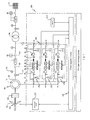
- the Fig. 1 shows a rotor 100 with angle-adjustable rotor blades 101 of a wind turbine, which is displaceable by wind in a rotary motion.
- the rotor 100 is connected via a gear 105 with a generator 110 and generates by the rotational movement of the rotor electrical power.
- the generator 110 has a generator rotor 115 and a generator stator 120, wherein the generator stator 120 is coupled to an electrical network 125 via at least one transformer 136.
- a switching element 130 eg contactor or active switch, such as IGBT or thyristor switch or the like
- a power switch 131 or the like are arranged in series, which connect the generator 110 to the electrical network 125 in the closed state , If necessary, for example when the operator of the electrical network 125 so requests, the generator 110 can be disconnected from the electrical network 125 by opening the switches.
- a device for measuring the electrical voltage 135 and a device for measuring the electric current 140 is furthermore arranged.
- the generator rotor 120 is coupled to an electrical system 200.
- the illustrated electrical system 200 includes the following electrical system units: a controller 210, a pitch system 220, and an inverter system 230.
- the controller 210 receives all essential parameters, such as environmental and plant parameters.
- Environmental parameters can be, for example, measurement data relating to the surroundings of the installation, such as air pressure, air temperature or wind speed, which are measured by means of sensors 240.
- System parameters are measured variables that relate to the operation of the system, which can be detected, inter alia, by measuring devices such as, for example, the device for measuring the electrical voltage 135 and the device for measuring the electrical current 140.
- the controller 210 is coupled to a remote monitoring system, where the remote monitoring system may be located at any location.
- remote monitoring system may be meant a location-independent monitoring system and / or a device for parking control.
- controller 210 In addition to the illustrated system units 220, 230, the controller 210 also typically controls a variety of auxiliary systems, such as auxiliaries. Wind tracking, cooling systems and oil supply, etc., which are not shown for reasons of clarity.
- the adjustment of the angle of the rotor blades 101 to the rotor 100 can be regulated via the pitch adjustment system 220.
- the control of the angular position of the rotor blades via the controller 210 which accesses the Blattverstellsystem.
- an optimum power generation of the wind energy plant can be set.
- a shutdown of the plant can also be achieved by the rotor blades are rotated in the so-called flag position.
- flag position is generally referred to the unscrewing of the rotor blades 101 from the wind, so that, as in a flag, the wind only a minimal attack surface is offered.
- control of the power generated by the generator in a the network requirements of the operator of an electrical network corresponding power via a so-called "double-fed" asynchronous generator.
- Known converter systems for the double-fed operation of a wind turbine generally have a machine-side inverter, which is coupled to the generator rotor, and a network-side inverter, which is coupled to the electrical network. Depending on the operating mode, the machine-side and the mains-side inverter are connected via a DC intermediate circuit or a DC intermediate circuit. Furthermore, known converter systems on machine and mains side protective devices and filters.
- the illustrated inverter system 230 shows an advantageous embodiment of an inverter system according to the invention.
- the functional module 250 comprises the following components: a machine-side protective device 251 (for example crowbar, lightning protection and / or overvoltage protection), a current measuring device 252, a machine-side filter 253 and a machine-side inverter 254. Furthermore, the functional module 250 comprises the components: network-side inverter 255, Mains choke 260, line-side current measuring device 256, line-side filter 257 and line-side protection device 258, wherein the machine-side inverter and the network-side inverter are connected via a DC voltage intermediate circuit 259.
- the converter system is advantageously designed such that a second functional function module is provided for the functional module, both being so dimensioned are that they can convert the dissipated via the generator rotor 115 power in equal parts.
- This version has the advantage that, if one functional module fails, the rotor power can be at least partially further converted and thus the system continues to be operational, even if it is restricted in terms of maximum power.
- the converter system 230 shown has a parallel module 270, which in the example is identical to the functional modules 250 and 250 '.
- the parallel module 270 is integrated into the converter system 230 in such a way that it can take over its function if one functional module 250, 250 'fails. Thus, even if a functional module 250, 250 'fails, it can be ensured that the power generation can be completely maintained.
- the functional modules 250 and 250 ' are separable from the electrical system 200 via machine-side switches 261, 261' as well as via network-side switches 262, 262 '.
- the converter control in turn being coupled to the control unit 210.
- the converter control can also be integrated directly in the control device or can be combined centrally in a unit which controls the entire converter (instead of the decentralized division shown in the individual modules).
- FIG. 2 an embodiment for the redundant design of a control device is shown.
- redundant controller 400 includes two cabinets 401 and 401 '.
- control cabinets 401 and 401 ' are each designed as a microcontroller operation management computer MC and MC' are arranged.
- the two operation control computers MC and MC ' are each supplied via a supply V and V' with electrical energy.
- the redundant control device 400 includes a function module "sensor” 402 to which a parallel module “sensor” 402 'is provided.
- a function module "sensor” 402 to which a parallel module "sensor” 402 'is provided.
- the sensor modules 402 and 402 'devices are summarized, on the required for the operation of the system measurement data can be detected.
- a measuring device W for detecting the generated electrical power for detecting the generated electrical power
- a measuring device Hz for detecting the frequency for detecting the frequency
- measuring devices ° C and v w for detecting z. B the ambient temperature and the wind speed.
- today's wind turbines have at least 50 to 100 different sensors, so this is a much simplified example for illustration. It is also conceivable to combine further or other sensory components in this functional module or in another functional module and to provide corresponding parallel modules, wherein the parallel modules according to the present invention may well be designed so that they do not have the same functions as the functional module but only perform similar functions, but by which a similar, similar or at least maintained function can be performed.
- the redundant control device 400 further comprises inputs E 1 , E 2 and E 3 arranged in the control cabinet 401 and the outputs A 1 and A 2 .
- the inputs E 1 , E 2 and E 3 are summarized in the illustrated embodiment to a functional module 410, wherein the inputs E 1 and E 2 each with the components W and Hz of the sensor module 402 and the input E 3 with the component ° C and v w are connected.
- the inputs E 1 ' , E 2' and E 3 ' and outputs A 1' and A '2 are correspondingly arranged in the control cabinet 401' and connected to the sensor module 402 ', the inputs E 1' , E 2 ' and E 3 'are combined to form a parallel module 410'.
- the outputs A 1 and A 1 ' are each connected to a converter control 403.
- the converter control 403 has the task of controlling the converter 404 in such a way that an electric power is generated which, on the one hand, controls the rotor speed in the setpoint range via the set torque and, on the other hand meets the requirements of the public electrical network.
- the outputs A 2 and A 2 connected to a Blattverstellsystem 405, via which the angular displacement of the rotor blades 406 for setting a required electrical power.
- the two operation control computers MC and MC' via a bus system respectively with the input function modules 410 and 410 ', the two supplies V and V' and the outputs A 1 , A 1 ' , A 2 and A 2 ' connected.
- the described exemplary embodiment of a redundant control device makes it possible for the corresponding replacement component or the corresponding parallel module to be activated if one component or one functional module fails.
- the operation control computer MC can access the sensor parallel module 402 'by switching the bus line. If, in addition, the defect occurs that the supply line between the MC and the output A 1 fails, then the operation control computer MC can access the converter control via the output A 1 ' by switching over the bus line. The same applies if z. B. the supply V of the operation control computer MC fails. In this case, there would then be the possibility on the one hand that the supply V 'takes over the supply of the operation management computer MC or that the operation management computer MC' is activated.
Landscapes
- Engineering & Computer Science (AREA)
- Power Engineering (AREA)
- Mechanical Engineering (AREA)
- Sustainable Energy (AREA)
- Chemical & Material Sciences (AREA)
- Combustion & Propulsion (AREA)
- Life Sciences & Earth Sciences (AREA)
- General Engineering & Computer Science (AREA)
- Sustainable Development (AREA)
- Business, Economics & Management (AREA)
- Emergency Management (AREA)
- Control Of Eletrric Generators (AREA)
- Wind Motors (AREA)
Applications Claiming Priority (3)
| Application Number | Priority Date | Filing Date | Title |
|---|---|---|---|
| DE10327344A DE10327344A1 (de) | 2003-06-16 | 2003-06-16 | Windenergieanlage |
| EP04739904A EP1634365B1 (fr) | 2003-06-16 | 2004-06-15 | Eolienne |
| PCT/EP2004/006434 WO2004114493A2 (fr) | 2003-06-16 | 2004-06-15 | Eolienne |
Related Parent Applications (2)
| Application Number | Title | Priority Date | Filing Date |
|---|---|---|---|
| EP04739904.3 Division | 2004-06-15 | ||
| EP04739904A Division EP1634365B1 (fr) | 2003-06-16 | 2004-06-15 | Eolienne |
Publications (3)
| Publication Number | Publication Date |
|---|---|
| EP2434148A2 true EP2434148A2 (fr) | 2012-03-28 |
| EP2434148A3 EP2434148A3 (fr) | 2018-01-24 |
| EP2434148B1 EP2434148B1 (fr) | 2023-04-12 |
Family
ID=33520678
Family Applications (4)
| Application Number | Title | Priority Date | Filing Date |
|---|---|---|---|
| EP11010031.0A Expired - Lifetime EP2434148B1 (fr) | 2003-06-16 | 2004-06-15 | Eolienne |
| EP04739904A Revoked EP1634365B1 (fr) | 2003-06-16 | 2004-06-15 | Eolienne |
| EP11010032.8A Ceased EP2434607A3 (fr) | 2003-06-16 | 2004-06-15 | Eolienne |
| EP11010030.2A Withdrawn EP2434632A3 (fr) | 2003-06-16 | 2004-06-15 | Eolienne |
Family Applications After (3)
| Application Number | Title | Priority Date | Filing Date |
|---|---|---|---|
| EP04739904A Revoked EP1634365B1 (fr) | 2003-06-16 | 2004-06-15 | Eolienne |
| EP11010032.8A Ceased EP2434607A3 (fr) | 2003-06-16 | 2004-06-15 | Eolienne |
| EP11010030.2A Withdrawn EP2434632A3 (fr) | 2003-06-16 | 2004-06-15 | Eolienne |
Country Status (6)
| Country | Link |
|---|---|
| US (1) | US7256508B2 (fr) |
| EP (4) | EP2434148B1 (fr) |
| DE (1) | DE10327344A1 (fr) |
| DK (1) | DK1634365T3 (fr) |
| ES (1) | ES2401140T3 (fr) |
| WO (1) | WO2004114493A2 (fr) |
Families Citing this family (94)
| Publication number | Priority date | Publication date | Assignee | Title |
|---|---|---|---|---|
| ES2627818T3 (es) * | 2001-09-28 | 2017-07-31 | Wobben Properties Gmbh | Procedimiento para el funcionamiento de un parque eólico |
| AU2003203152B2 (en) * | 2003-02-07 | 2006-11-09 | Vestas Wind Systems A/S | Method for controlling a power-grid connected wind turbine generator during grid faults and apparatus for implementing said method |
| DE10320087B4 (de) * | 2003-05-05 | 2005-04-28 | Aloys Wobben | Verfahren zum Betreiben eines Windparks |
| ATE377286T1 (de) * | 2003-07-15 | 2007-11-15 | Gamesa Innovation & Tech Sl | Steuer- und schutzgerät für ein doppelgespeistes induktionsgeneratorsystem |
| CA2592298C (fr) * | 2004-12-30 | 2014-05-13 | Vestas Wind Systems A/S | Eolienne a systeme de commande a redondance multiple et procede de commande |
| DE102005018996A1 (de) * | 2005-04-22 | 2006-10-26 | Repower Systems Ag | Steuerungsvorrichtung für mehrere Windenergieanlagen, Windpark mit mehreren Windenergieanlagen, Verfahren zur Nachrüstung einer vorhandenen Steuerungsvorrichtung |
| US9306473B2 (en) * | 2005-07-01 | 2016-04-05 | Vestas Wind Systems A/S | Variable rotor speed wind turbine, wind park, method of transmitting electric power and method of servicing or inspecting a variable rotor speed wind turbine |
| US7476985B2 (en) * | 2005-07-22 | 2009-01-13 | Gamesa Innovation & Technology, S.L. | Method of operating a wind turbine |
| EP1752660B1 (fr) * | 2005-08-12 | 2013-04-03 | General Electric Company | Dispositif de protection contre les surtensions dans une éolienne |
| DE102005045516A1 (de) * | 2005-09-22 | 2007-03-29 | Daubner & Stommel GbR Bau-Werk-Planung (vertretungsberechtigter Gesellschafter: Matthias Stommel, 27777 Ganderkesee) | Verfahren zur Anpassung einer Windenergieanlage an gegebene Windverhältnisse |
| DE102005057610A1 (de) * | 2005-12-02 | 2007-06-06 | Repower Systems Ag | Windenergieanlage mit einer Nachschmiereinrichtung für Generatorlager |
| ES2291103B1 (es) * | 2005-12-30 | 2009-02-01 | Universidad Publica De Navarra | Metodo y sistema de control del convertidor de una instalacion de generacion electrica conectada a una red electrica ante la presencia de huecos de tension en dicha red. |
| US8032614B2 (en) | 2006-04-30 | 2011-10-04 | General Electric Company | Method for configuring a windfarm network |
| DE102006021982C5 (de) * | 2006-05-10 | 2010-10-07 | Repower Systems Ag | Gestaffelt abschaltbarer Windpark |
| US7391126B2 (en) * | 2006-06-30 | 2008-06-24 | General Electric Company | Systems and methods for an integrated electrical sub-system powered by wind energy |
| US7560823B2 (en) * | 2006-06-30 | 2009-07-14 | General Electric Company | Wind energy system and method of operation thereof |
| DE102006034251B8 (de) | 2006-07-21 | 2014-08-21 | Senvion Se | Verfahren zum Betreiben einer Windenergieanlage |
| FI119086B (fi) * | 2006-11-06 | 2008-07-15 | Abb Oy | Menetelmä ja järjestely tuulivoimalan yhteydessä |
| WO2008077974A1 (fr) * | 2006-12-22 | 2008-07-03 | Wind To Power System, S.L. | Générateur asynchrone à double alimentation |
| US7531911B2 (en) * | 2006-12-22 | 2009-05-12 | Ingeteam Energy, S.A. | Reactive power control for operating a wind farm |
| WO2008081049A1 (fr) * | 2006-12-28 | 2008-07-10 | Wind To Power System, S.L. | Générateur asynchrone avec régulation de la tension appliquée sur le stator |
| DE102007027081B4 (de) * | 2007-06-12 | 2011-01-05 | Wolfgang Zwick | Überspannungsschutz-Vorrichtung für einen Wechselrichter eines Windenergie-Konverters |
| DE102007030494A1 (de) * | 2007-06-30 | 2009-01-02 | Nordex Energy Gmbh | Verfahren zum Anfahren einer Windenergieanlage nach einer Betriebspause und Windenergieanlage, die das Verfahren ausführen kann |
| DE102007057788B4 (de) * | 2007-11-30 | 2012-09-13 | Nordex Energy Gmbh | Verfahren zum Versorgen einer Azimutdrehverbindung mit Schmiermittel |
| US8805595B2 (en) * | 2008-01-17 | 2014-08-12 | General Electric Company | Wind turbine arranged for independent operation of its components and related method and computer program |
| EP2080903B2 (fr) | 2008-01-21 | 2020-02-12 | Siemens Gamesa Renewable Energy A/S | Système à sécurité intégrée pour la commande d'éoliennes |
| DE102008009278A1 (de) * | 2008-02-15 | 2009-08-27 | Converteam Technology Ltd., Rugby | Mehrphasige elektrische Schaltung zum Abschalten eines über jeweils einen Drehstromsteller geführten Stroms |
| CN101970866B (zh) * | 2008-03-07 | 2013-03-06 | 维斯塔斯风力系统有限公司 | 用于风力涡轮机冗余控制的控制系统和方法 |
| ES2327487B1 (es) * | 2008-03-28 | 2010-08-03 | Ingeteam Energy, S.A. | Sistema y metodo de operacion asincrona aplicable a un aerogenerador del tipo doblemente alimentado (dfig). |
| CA2719434A1 (fr) | 2008-03-28 | 2009-10-01 | Ingeteam Energy, S.A. | Procede et systeme pour faire fonctionner un aerogenerateur |
| GB0809235D0 (en) * | 2008-05-21 | 2008-06-25 | Poweroasis Ltd | Supervisory system controller for use with a renewable energy powered radio telecommunications site |
| US8093737B2 (en) * | 2008-05-29 | 2012-01-10 | General Electric Company | Method for increasing energy capture in a wind turbine |
| US20090295231A1 (en) * | 2008-05-30 | 2009-12-03 | Gaffney Shawn J | Intelligent Power Collection Network |
| DE102008025944C5 (de) * | 2008-05-30 | 2013-08-22 | Repower Systems Se | Überwachungseinrichtung für Pitchsysteme von Windenergieanlagen |
| JP4480777B2 (ja) * | 2008-06-04 | 2010-06-16 | 三菱電機株式会社 | 可変速同期発電電動機 |
| US7944068B2 (en) * | 2008-06-30 | 2011-05-17 | General Electric Company | Optimizing converter protection for wind turbine generators |
| WO2010000315A1 (fr) * | 2008-07-02 | 2010-01-07 | Vestas Wind Systems A/S | Système convertisseur modulaire supportant une suppression d'harmoniques |
| EP2329581A4 (fr) | 2008-09-03 | 2013-12-04 | Exro Technologies Inc | Système de conversion de puissance pour un générateur multi-étagé |
| DE102008037449B4 (de) * | 2008-10-14 | 2010-10-14 | Kenersys Gmbh | Windenergieanlage |
| DE102008057934C5 (de) * | 2008-11-19 | 2020-09-17 | Nordex Energy Gmbh | Windenergieanlage mit einer zentralen Steuerungseinrichtung und einer Steuerungseinheit im Rotor sowie Verfahren zum Betreiben einer derartigen Windenergieanlage |
| SE0950190A1 (sv) * | 2009-03-25 | 2010-09-26 | Ge Wind Energy Norway As | Mångfald kabinett |
| ES2618029T3 (es) * | 2009-04-03 | 2017-06-20 | Xemc Darwind B.V. | Operación de un parque eléctrico conectado en red eléctrica independiente |
| EP2242159B1 (fr) * | 2009-04-17 | 2016-04-13 | Vestas Wind Systems A/S | Parc éolien, procédé de correction de déséquilibres de tension et turbine d'éolienne |
| US8138620B2 (en) * | 2009-06-12 | 2012-03-20 | General Electric Company | Methods and systems for operating a wind turbine power converter |
| DE102009030725A1 (de) | 2009-06-26 | 2010-12-30 | Repower Systems Ag | Windpark und Verfahren zum Regeln eines Windparks |
| US8504213B2 (en) * | 2009-06-26 | 2013-08-06 | General Electric Company | Regulation of generating plant |
| ATE546646T1 (de) * | 2009-10-06 | 2012-03-15 | Siemens Ag | Verfahren zur steuerung einer windturbine bei thermischen überlastungen |
| DE102009059284A1 (de) | 2009-12-22 | 2011-06-30 | 2-B Energy B.V. | Windkraftanlage |
| ES2657680T3 (es) * | 2010-01-14 | 2018-03-06 | Siemens Aktiengesellschaft | Dispositivo convertidor y método para convertir energía eléctrica |
| EP2346134B1 (fr) * | 2010-01-14 | 2017-09-27 | Siemens Aktiengesellschaft | Dispositif de convertisseur et procédé de conversion d'alimentation électrique |
| US8872375B2 (en) * | 2010-03-05 | 2014-10-28 | Deka Products Limited Partnership | Wind turbine apparatus, systems and methods |
| KR101377319B1 (ko) * | 2010-03-23 | 2014-03-25 | 에이비비 테크놀로지 아게 | 전압 소스 컨버터 및 그 고장 처리 방법 |
| EP2386753A1 (fr) * | 2010-05-12 | 2011-11-16 | Wind To Power System, S.l. | Circuit d'excitation pour un générateur asynchrone et procédé d'excitation pour un générateur asynchrone |
| ES2692361T3 (es) * | 2010-07-09 | 2018-12-03 | Vestas Wind Systems A/S | Disposición de suministro de energía de aparamenta de conmutación de alta tensión para una instalación de turbina eólica |
| US8558409B2 (en) * | 2010-07-09 | 2013-10-15 | Vestas Wind Systems A/S | High voltage switchgear power supply arrangement for a wind turbine facility |
| US8471534B2 (en) * | 2010-08-26 | 2013-06-25 | General Electric Company | Fault ride through switch for power generation system |
| US8928179B2 (en) * | 2010-12-06 | 2015-01-06 | Hamilton Sundstrand Corporation | No break power transfer for power generating system |
| EP2466715A3 (fr) * | 2010-12-20 | 2017-08-30 | FeCon GmbH | Unité de commutation USV et procédé d'alimentation en électricité sans interruption d'utilisateurs d'une installation de production de courant |
| US8631275B2 (en) * | 2010-12-28 | 2014-01-14 | Vestas Wind Systems A/S | Controller arrangement of an electrical power transfer system of a wind turbine |
| US8957535B2 (en) * | 2011-01-17 | 2015-02-17 | Vestas Wind Systems A/S | Fault tolerant wind turbine converter |
| EP2492504B1 (fr) * | 2011-02-25 | 2018-01-31 | Siemens Aktiengesellschaft | Éolienne |
| EP2691044A2 (fr) * | 2011-03-30 | 2014-02-05 | Vestas Wind Systems A/S | Système de protection contre les incendies insensible aux défaillances |
| WO2012130241A1 (fr) | 2011-03-30 | 2012-10-04 | Vestas Wind Systems A/S | Installation de génératrices éoliennes équipée d'une commande de puissance en temps réel de haute fiabilité |
| DK201170325A (en) * | 2011-06-24 | 2012-12-25 | Vestas Wind Sys As | Wind turbine with decentralized voting |
| DE102011006670A1 (de) * | 2011-04-01 | 2012-10-04 | Aloys Wobben | Windenergieanlage und Verfahren zum Betreiben einer Windenergieanlage |
| DE102011001786A1 (de) * | 2011-04-04 | 2012-10-04 | Woodward Kempen Gmbh | Schaltschrankanordnung einer Vorrichtung zur Erzeugung elektrischer Energie |
| WO2012139656A1 (fr) * | 2011-04-15 | 2012-10-18 | Siemens Aktiengesellschaft | Réseau de distribution d'énergie et procédé d'exploitation de ce réseau |
| DE102011076925A1 (de) * | 2011-06-03 | 2012-12-06 | Siemens Aktiengesellschaft | Elektrische Asynchronmaschine und Windkraftanlage |
| CN102222973B (zh) * | 2011-06-14 | 2013-04-17 | 湘潭世通电气有限公司 | 用于大型风力发电机组变桨控制器的直流电源装置 |
| JP6062946B2 (ja) * | 2011-09-22 | 2017-01-18 | インゲチーム パワー テクノロジー エス アー | 電気エネルギー変換システム及び方法 |
| US9080553B2 (en) * | 2012-01-20 | 2015-07-14 | General Electric Company | Method and apparatus for control of redundant devices in a wind turbine |
| US9853453B2 (en) * | 2012-04-20 | 2017-12-26 | Siemens Aktiengesellschaft | Wind park control system |
| IN2014DN10678A (fr) * | 2012-07-19 | 2015-08-28 | Vestas Wind Sys As | |
| US20140142775A1 (en) * | 2012-09-04 | 2014-05-22 | Eco Power Design LLC | Power production systems with a safety and reliability monitoring system and methods for improving safety and reliability for power production systems |
| DK177684B1 (en) * | 2012-12-21 | 2014-03-03 | Envision Energy Denmark Aps | Wind turbine having a HTS generator with a plurality of phases |
| US9048764B2 (en) * | 2013-05-29 | 2015-06-02 | General Electric Company | Connection for improved current balancing in a parallel bridge power converter |
| US20140361624A1 (en) * | 2013-06-10 | 2014-12-11 | Active Power, Inc. | Apparatus and methods for control of load power quality in uninterruptible power systems |
| WO2016011454A1 (fr) | 2014-07-18 | 2016-01-21 | Eip Technologies, Inc. | Génération d'énergie éolienne directe |
| US10253746B2 (en) | 2014-09-25 | 2019-04-09 | Eip Technologies, Inc. | Renewable energy generation based on water waves |
| DE102015215302A1 (de) | 2015-08-11 | 2017-03-30 | Aktiebolaget Skf | Automatisches Schmiersystem für ein Lager und Verfahren zum Betreiben eines automatischen Schmiersystems |
| ES2618298B1 (es) * | 2015-12-18 | 2018-04-13 | Gamesa Innovation & Technology S.L. | Sistema de generación de energía eléctrica de una turbina eólica de convertidores múltiples y procedimiento de control del mismo |
| DE102016009686A1 (de) * | 2016-08-11 | 2018-02-15 | Reetec Gmbh Regenerative Energie- Und Elektrotechnik | Schnittstellenschrank für Offshore Windenergieanlagen |
| CN106286129B (zh) | 2016-10-12 | 2021-04-06 | 北京金风科创风电设备有限公司 | 风力发电机组及其控制方法 |
| EP3316437A1 (fr) * | 2016-10-26 | 2018-05-02 | MHI Vestas Offshore Wind A/S | Fourniture d'une alimentation auxiliaire lorsqu'une connexion à la haute tension est non fonctionnelle |
| CN108240284A (zh) * | 2016-12-26 | 2018-07-03 | 北京金风科创风电设备有限公司 | 基于风力发电机组系统功能的数据处理方法和装置 |
| US10784685B2 (en) * | 2017-05-08 | 2020-09-22 | General Electric Company | Electrical power systems and subsystems |
| CN109149626B (zh) * | 2017-12-28 | 2022-01-25 | 北京金风科创风电设备有限公司 | 发电机组的运行控制方法、装置及系统 |
| US10998760B2 (en) * | 2018-09-27 | 2021-05-04 | General Electric Company | System and method for controlling uninterruptible power supply of electrical power systems |
| CN111102138A (zh) * | 2019-12-27 | 2020-05-05 | 天津瑞源电气有限公司 | 一种变桨系统测试系统 |
| US11894672B2 (en) | 2020-07-10 | 2024-02-06 | Vestas Wind Systems A/S | Wind turbine generator fault protection system |
| US11661919B2 (en) | 2021-01-20 | 2023-05-30 | General Electric Company | Odometer-based control of a wind turbine power system |
| US11635060B2 (en) | 2021-01-20 | 2023-04-25 | General Electric Company | System for operating a wind turbine using cumulative load histograms based on actual operation thereof |
| US11728654B2 (en) | 2021-03-19 | 2023-08-15 | General Electric Renovables Espana, S.L. | Systems and methods for operating power generating assets |
| US11784602B2 (en) | 2021-07-01 | 2023-10-10 | Regal Beloit America, Inc. | Systems and methods for hybrid drive control for an electric motor |
Citations (1)
| Publication number | Priority date | Publication date | Assignee | Title |
|---|---|---|---|---|
| DE10040273A1 (de) | 2000-08-14 | 2002-02-28 | Aloys Wobben | Windenergieanlage |
Family Cites Families (18)
| Publication number | Priority date | Publication date | Assignee | Title |
|---|---|---|---|---|
| US2911541A (en) * | 1954-03-15 | 1959-11-03 | Neufville Jean Marie Marcel | Generator system for supplying auxiliary power on board ship |
| US4205235A (en) * | 1978-03-06 | 1980-05-27 | The United States Of America As Represented By The Secretary Of The Navy | Automatic electrical load matching device for wind generators |
| DE2827443C2 (de) | 1978-06-22 | 1982-08-26 | Siemens Ag, 1000 Berlin Und 8000 Muenchen | Gesicherte Stromrichteranordnung |
| US4584486A (en) * | 1984-04-09 | 1986-04-22 | The Boeing Company | Blade pitch control of a wind turbine |
| US5083039B1 (en) | 1991-02-01 | 1999-11-16 | Zond Energy Systems Inc | Variable speed wind turbine |
| US5734255A (en) * | 1996-03-13 | 1998-03-31 | Alaska Power Systems Inc. | Control system and circuits for distributed electrical power generating stations |
| US20020029097A1 (en) * | 2000-04-07 | 2002-03-07 | Pionzio Dino J. | Wind farm control system |
| US6566764B2 (en) * | 2000-05-23 | 2003-05-20 | Vestas Wind Systems A/S, R&D | Variable speed wind turbine having a matrix converter |
| US6946750B2 (en) * | 2000-08-14 | 2005-09-20 | Aloys Wobben | Wind power plant having a power generation redundancy system |
| DE10044096A1 (de) * | 2000-09-07 | 2002-04-04 | Aloys Wobben | Inselnetz und Verfahren zum Betrieb eines Inselnetzes |
| DE10117212A1 (de) * | 2001-04-06 | 2002-10-10 | Dewind Ag | Verfahren zum Betrieb einer Windenergieanlage |
| DE10134883A1 (de) * | 2001-07-18 | 2003-01-30 | Abb Research Ltd | Verfahren und Vorrichtung zur drehzahlstellbaren leistungselektronischen Regelung einer getriebelosen Windkraftanlage |
| DE10137272A1 (de) * | 2001-07-31 | 2003-02-27 | Aloys Wobben | Frühwarnsystem für Windenergieanlagen |
| DE60233421D1 (de) * | 2001-09-28 | 2009-10-01 | Vestas Wind Sys As | Verfahren und rechnersystem zur verarbeitung von betriebsdaten von windenergieanlagen |
| CN100356683C (zh) * | 2002-01-29 | 2007-12-19 | 威斯塔斯风力系统公开有限公司 | 用于风力装置中的电路结构 |
| US7071579B2 (en) * | 2002-06-07 | 2006-07-04 | Global Energyconcepts,Llc | Wind farm electrical system |
| ATE377286T1 (de) * | 2003-07-15 | 2007-11-15 | Gamesa Innovation & Tech Sl | Steuer- und schutzgerät für ein doppelgespeistes induktionsgeneratorsystem |
| US7119452B2 (en) * | 2003-09-03 | 2006-10-10 | General Electric Company | Voltage control for wind generators |
-
2003
- 2003-06-16 DE DE10327344A patent/DE10327344A1/de not_active Ceased
-
2004
- 2004-06-15 EP EP11010031.0A patent/EP2434148B1/fr not_active Expired - Lifetime
- 2004-06-15 WO PCT/EP2004/006434 patent/WO2004114493A2/fr active Application Filing
- 2004-06-15 ES ES04739904T patent/ES2401140T3/es not_active Expired - Lifetime
- 2004-06-15 EP EP04739904A patent/EP1634365B1/fr not_active Revoked
- 2004-06-15 US US10/559,924 patent/US7256508B2/en not_active Expired - Lifetime
- 2004-06-15 DK DK04739904.3T patent/DK1634365T3/da active
- 2004-06-15 EP EP11010032.8A patent/EP2434607A3/fr not_active Ceased
- 2004-06-15 EP EP11010030.2A patent/EP2434632A3/fr not_active Withdrawn
Patent Citations (1)
| Publication number | Priority date | Publication date | Assignee | Title |
|---|---|---|---|---|
| DE10040273A1 (de) | 2000-08-14 | 2002-02-28 | Aloys Wobben | Windenergieanlage |
Also Published As
| Publication number | Publication date |
|---|---|
| EP2434148A3 (fr) | 2018-01-24 |
| EP2434607A2 (fr) | 2012-03-28 |
| EP2434632A2 (fr) | 2012-03-28 |
| US7256508B2 (en) | 2007-08-14 |
| WO2004114493A3 (fr) | 2005-03-03 |
| ES2401140T3 (es) | 2013-04-17 |
| EP2434148B1 (fr) | 2023-04-12 |
| US20060214428A1 (en) | 2006-09-28 |
| DE10327344A1 (de) | 2005-01-27 |
| EP2434607A3 (fr) | 2018-02-21 |
| EP1634365A2 (fr) | 2006-03-15 |
| EP2434632A3 (fr) | 2018-01-24 |
| EP1634365B1 (fr) | 2013-01-02 |
| DK1634365T3 (da) | 2013-03-18 |
| WO2004114493A2 (fr) | 2004-12-29 |
Similar Documents
| Publication | Publication Date | Title |
|---|---|---|
| EP1634365B1 (fr) | Eolienne | |
| EP2102495B1 (fr) | Dispositif d'éolienne comportant une régulation de système inverse et procédé d'utilisation | |
| EP1752659B2 (fr) | Méthode d'opération d'un parc d'éoliennes et parc d'éoliennes | |
| EP2245728B1 (fr) | Éolienne à régulation du convertisseur | |
| DE102006014121B4 (de) | System und Verfahren zur Regelung der Nennleistung einer Windkraftanlage | |
| EP2457320B1 (fr) | Procédé de fonctionnement d'une turbine éolienne et turbine éolienne associée | |
| DE102007052863B4 (de) | Verfahren zum Betreiben einer Windenergieanlage | |
| WO2005017350A1 (fr) | Installation eolienne munie d'un dispositif de reglage des pales de rotor | |
| DE102009044570A1 (de) | Windkraftanlage | |
| EP2284634B1 (fr) | Procédé et agencement pour le contrôle de paramètres de configuration automatique dans des éoliennes | |
| DE102012204239A1 (de) | Verfahren zum Steuern einer Windenergieanlage | |
| DE102007049313A1 (de) | Rotorblattverstellsystem | |
| EP3533125B1 (fr) | Procédé de commande d'une installation électrique éolienne | |
| DE102011079939A1 (de) | Steuervorrichtung zum Steuern der Winkeleinstellung eines Rotorblatts einer Windkraftanlage und Windkraftanlage | |
| WO2020079059A1 (fr) | Procédé servant à faire fonctionner une éolienne en cas d'incident | |
| WO2012025348A2 (fr) | Système de pas pour éolienne | |
| DE102009003788A1 (de) | Blattwinkelverstellantrieb für eine Windkraftanlage | |
| EP3940226B1 (fr) | Éolienne et procédé de fonctionnement d'une éolienne | |
| DE102019000025A1 (de) | Windenergieanlage | |
| EP2616674B1 (fr) | Éolienne et procédé pour l'arrêt progressif de manière régulée d'une éolienne | |
| EP3848576A1 (fr) | Procédé de commande d'un processus de mise en circuit d'une éolienne ainsi qu'une telle éolienne | |
| DE102019117169A1 (de) | Verfahren zum Einspeisen elektrischer Leistung mittels eines Windparks | |
| DE102018006832A1 (de) | Verfahren und Steuerung zur Kompensation einer geplanten anlagenbedingten Leistungsbeeinträchtigung einer Windenergieanlage |
Legal Events
| Date | Code | Title | Description |
|---|---|---|---|
| PUAI | Public reference made under article 153(3) epc to a published international application that has entered the european phase |
Free format text: ORIGINAL CODE: 0009012 |
|
| AC | Divisional application: reference to earlier application |
Ref document number: 1634365 Country of ref document: EP Kind code of ref document: P |
|
| AK | Designated contracting states |
Kind code of ref document: A2 Designated state(s): AT BE BG CH CY CZ DE DK EE ES FI FR GB GR HU IE IT LI LU MC NL PL PT RO SE SI SK TR |
|
| AX | Request for extension of the european patent |
Extension state: AL HR LT LV MK |
|
| RIN1 | Information on inventor provided before grant (corrected) |
Inventor name: MATZEN, BJOERN Inventor name: ZEUMER, JOERG Inventor name: ALTEMARK, JENS |
|
| RAP1 | Party data changed (applicant data changed or rights of an application transferred) |
Owner name: REPOWER SYSTEMS SE |
|
| RAP1 | Party data changed (applicant data changed or rights of an application transferred) |
Owner name: SENVION SE |
|
| RAP1 | Party data changed (applicant data changed or rights of an application transferred) |
Owner name: SENVION GMBH |
|
| PUAL | Search report despatched |
Free format text: ORIGINAL CODE: 0009013 |
|
| AK | Designated contracting states |
Kind code of ref document: A3 Designated state(s): AT BE BG CH CY CZ DE DK EE ES FI FR GB GR HU IE IT LI LU MC NL PL PT RO SE SI SK TR |
|
| AX | Request for extension of the european patent |
Extension state: AL HR LT LV MK |
|
| RIC1 | Information provided on ipc code assigned before grant |
Ipc: H02J 3/38 20060101ALI20171218BHEP Ipc: F03D 7/04 20060101ALI20171218BHEP Ipc: H02J 9/06 20060101ALI20171218BHEP Ipc: H02J 13/00 20060101ALI20171218BHEP Ipc: H02M 7/48 20070101AFI20171218BHEP Ipc: F03D 9/25 20160101ALI20171218BHEP |
|
| STAA | Information on the status of an ep patent application or granted ep patent |
Free format text: STATUS: REQUEST FOR EXAMINATION WAS MADE |
|
| 17P | Request for examination filed |
Effective date: 20180723 |
|
| RBV | Designated contracting states (corrected) |
Designated state(s): AT BE BG CH CY CZ DE DK EE ES FI FR GB GR HU IE IT LI LU MC NL PL PT RO SE SI SK TR |
|
| STAA | Information on the status of an ep patent application or granted ep patent |
Free format text: STATUS: EXAMINATION IS IN PROGRESS |
|
| 17Q | First examination report despatched |
Effective date: 20200123 |
|
| STAA | Information on the status of an ep patent application or granted ep patent |
Free format text: STATUS: EXAMINATION IS IN PROGRESS |
|
| GRAP | Despatch of communication of intention to grant a patent |
Free format text: ORIGINAL CODE: EPIDOSNIGR1 |
|
| STAA | Information on the status of an ep patent application or granted ep patent |
Free format text: STATUS: GRANT OF PATENT IS INTENDED |
|
| INTG | Intention to grant announced |
Effective date: 20210409 |
|
| GRAJ | Information related to disapproval of communication of intention to grant by the applicant or resumption of examination proceedings by the epo deleted |
Free format text: ORIGINAL CODE: EPIDOSDIGR1 |
|
| STAA | Information on the status of an ep patent application or granted ep patent |
Free format text: STATUS: EXAMINATION IS IN PROGRESS |
|
| INTC | Intention to grant announced (deleted) | ||
| RAP1 | Party data changed (applicant data changed or rights of an application transferred) |
Owner name: SIEMENS GAMESA RENEWABLE ENERGY SERVICE GMBH |
|
| STAA | Information on the status of an ep patent application or granted ep patent |
Free format text: STATUS: EXAMINATION IS IN PROGRESS |
|
| RAP3 | Party data changed (applicant data changed or rights of an application transferred) |
Owner name: SIEMENS GAMESA RENEWABLE ENERGY SERVICE GMBH |
|
| GRAP | Despatch of communication of intention to grant a patent |
Free format text: ORIGINAL CODE: EPIDOSNIGR1 |
|
| STAA | Information on the status of an ep patent application or granted ep patent |
Free format text: STATUS: GRANT OF PATENT IS INTENDED |
|
| INTG | Intention to grant announced |
Effective date: 20221028 |
|
| GRAS | Grant fee paid |
Free format text: ORIGINAL CODE: EPIDOSNIGR3 |
|
| GRAA | (expected) grant |
Free format text: ORIGINAL CODE: 0009210 |
|
| STAA | Information on the status of an ep patent application or granted ep patent |
Free format text: STATUS: THE PATENT HAS BEEN GRANTED |
|
| AC | Divisional application: reference to earlier application |
Ref document number: 1634365 Country of ref document: EP Kind code of ref document: P |
|
| AK | Designated contracting states |
Kind code of ref document: B1 Designated state(s): AT BE BG CH CY CZ DE DK EE ES FI FR GB GR HU IE IT LI LU MC NL PL PT RO SE SI SK TR |
|
| REG | Reference to a national code |
Ref country code: GB Ref legal event code: FG4D Free format text: NOT ENGLISH |
|
| REG | Reference to a national code |
Ref country code: CH Ref legal event code: EP |
|
| REG | Reference to a national code |
Ref country code: DE Ref legal event code: R096 Ref document number: 502004015889 Country of ref document: DE |
|
| REG | Reference to a national code |
Ref country code: IE Ref legal event code: FG4D Free format text: LANGUAGE OF EP DOCUMENT: GERMAN |
|
| REG | Reference to a national code |
Ref country code: AT Ref legal event code: REF Ref document number: 1560343 Country of ref document: AT Kind code of ref document: T Effective date: 20230515 |
|
| PGFP | Annual fee paid to national office [announced via postgrant information from national office to epo] |
Ref country code: FR Payment date: 20230622 Year of fee payment: 20 Ref country code: DE Payment date: 20230620 Year of fee payment: 20 |
|
| REG | Reference to a national code |
Ref country code: NL Ref legal event code: MP Effective date: 20230412 |
|
| PG25 | Lapsed in a contracting state [announced via postgrant information from national office to epo] |
Ref country code: NL Free format text: LAPSE BECAUSE OF FAILURE TO SUBMIT A TRANSLATION OF THE DESCRIPTION OR TO PAY THE FEE WITHIN THE PRESCRIBED TIME-LIMIT Effective date: 20230412 |
|
| PG25 | Lapsed in a contracting state [announced via postgrant information from national office to epo] |
Ref country code: SE Free format text: LAPSE BECAUSE OF FAILURE TO SUBMIT A TRANSLATION OF THE DESCRIPTION OR TO PAY THE FEE WITHIN THE PRESCRIBED TIME-LIMIT Effective date: 20230412 Ref country code: PT Free format text: LAPSE BECAUSE OF FAILURE TO SUBMIT A TRANSLATION OF THE DESCRIPTION OR TO PAY THE FEE WITHIN THE PRESCRIBED TIME-LIMIT Effective date: 20230814 Ref country code: ES Free format text: LAPSE BECAUSE OF FAILURE TO SUBMIT A TRANSLATION OF THE DESCRIPTION OR TO PAY THE FEE WITHIN THE PRESCRIBED TIME-LIMIT Effective date: 20230412 |
|
| PGFP | Annual fee paid to national office [announced via postgrant information from national office to epo] |
Ref country code: GB Payment date: 20230622 Year of fee payment: 20 |
|
| PG25 | Lapsed in a contracting state [announced via postgrant information from national office to epo] |
Ref country code: PL Free format text: LAPSE BECAUSE OF FAILURE TO SUBMIT A TRANSLATION OF THE DESCRIPTION OR TO PAY THE FEE WITHIN THE PRESCRIBED TIME-LIMIT Effective date: 20230412 Ref country code: GR Free format text: LAPSE BECAUSE OF FAILURE TO SUBMIT A TRANSLATION OF THE DESCRIPTION OR TO PAY THE FEE WITHIN THE PRESCRIBED TIME-LIMIT Effective date: 20230713 |
|
| PG25 | Lapsed in a contracting state [announced via postgrant information from national office to epo] |
Ref country code: FI Free format text: LAPSE BECAUSE OF FAILURE TO SUBMIT A TRANSLATION OF THE DESCRIPTION OR TO PAY THE FEE WITHIN THE PRESCRIBED TIME-LIMIT Effective date: 20230412 |
|
| REG | Reference to a national code |
Ref country code: DE Ref legal event code: R097 Ref document number: 502004015889 Country of ref document: DE |
|
| PG25 | Lapsed in a contracting state [announced via postgrant information from national office to epo] |
Ref country code: SK Free format text: LAPSE BECAUSE OF FAILURE TO SUBMIT A TRANSLATION OF THE DESCRIPTION OR TO PAY THE FEE WITHIN THE PRESCRIBED TIME-LIMIT Effective date: 20230412 |
|
| PG25 | Lapsed in a contracting state [announced via postgrant information from national office to epo] |
Ref country code: MC Free format text: LAPSE BECAUSE OF FAILURE TO SUBMIT A TRANSLATION OF THE DESCRIPTION OR TO PAY THE FEE WITHIN THE PRESCRIBED TIME-LIMIT Effective date: 20230412 |
|
| PG25 | Lapsed in a contracting state [announced via postgrant information from national office to epo] |
Ref country code: SK Free format text: LAPSE BECAUSE OF FAILURE TO SUBMIT A TRANSLATION OF THE DESCRIPTION OR TO PAY THE FEE WITHIN THE PRESCRIBED TIME-LIMIT Effective date: 20230412 Ref country code: RO Free format text: LAPSE BECAUSE OF FAILURE TO SUBMIT A TRANSLATION OF THE DESCRIPTION OR TO PAY THE FEE WITHIN THE PRESCRIBED TIME-LIMIT Effective date: 20230412 Ref country code: MC Free format text: LAPSE BECAUSE OF FAILURE TO SUBMIT A TRANSLATION OF THE DESCRIPTION OR TO PAY THE FEE WITHIN THE PRESCRIBED TIME-LIMIT Effective date: 20230412 Ref country code: EE Free format text: LAPSE BECAUSE OF FAILURE TO SUBMIT A TRANSLATION OF THE DESCRIPTION OR TO PAY THE FEE WITHIN THE PRESCRIBED TIME-LIMIT Effective date: 20230412 Ref country code: DK Free format text: LAPSE BECAUSE OF FAILURE TO SUBMIT A TRANSLATION OF THE DESCRIPTION OR TO PAY THE FEE WITHIN THE PRESCRIBED TIME-LIMIT Effective date: 20230412 Ref country code: CZ Free format text: LAPSE BECAUSE OF FAILURE TO SUBMIT A TRANSLATION OF THE DESCRIPTION OR TO PAY THE FEE WITHIN THE PRESCRIBED TIME-LIMIT Effective date: 20230412 |
|
| REG | Reference to a national code |
Ref country code: CH Ref legal event code: PL |
|
| PLBE | No opposition filed within time limit |
Free format text: ORIGINAL CODE: 0009261 |
|
| STAA | Information on the status of an ep patent application or granted ep patent |
Free format text: STATUS: NO OPPOSITION FILED WITHIN TIME LIMIT |
|
| REG | Reference to a national code |
Ref country code: BE Ref legal event code: MM Effective date: 20230630 |
|
| PG25 | Lapsed in a contracting state [announced via postgrant information from national office to epo] |
Ref country code: LU Free format text: LAPSE BECAUSE OF NON-PAYMENT OF DUE FEES Effective date: 20230615 |
|
| 26N | No opposition filed |
Effective date: 20240115 |
|
| REG | Reference to a national code |
Ref country code: IE Ref legal event code: MM4A |
|
| PG25 | Lapsed in a contracting state [announced via postgrant information from national office to epo] |
Ref country code: LU Free format text: LAPSE BECAUSE OF NON-PAYMENT OF DUE FEES Effective date: 20230615 |
|
| PG25 | Lapsed in a contracting state [announced via postgrant information from national office to epo] |
Ref country code: IE Free format text: LAPSE BECAUSE OF NON-PAYMENT OF DUE FEES Effective date: 20230615 |
|
| PG25 | Lapsed in a contracting state [announced via postgrant information from national office to epo] |
Ref country code: IE Free format text: LAPSE BECAUSE OF NON-PAYMENT OF DUE FEES Effective date: 20230615 Ref country code: CH Free format text: LAPSE BECAUSE OF NON-PAYMENT OF DUE FEES Effective date: 20230630 |
|
| PG25 | Lapsed in a contracting state [announced via postgrant information from national office to epo] |
Ref country code: SI Free format text: LAPSE BECAUSE OF FAILURE TO SUBMIT A TRANSLATION OF THE DESCRIPTION OR TO PAY THE FEE WITHIN THE PRESCRIBED TIME-LIMIT Effective date: 20230412 |
|
| PG25 | Lapsed in a contracting state [announced via postgrant information from national office to epo] |
Ref country code: SI Free format text: LAPSE BECAUSE OF FAILURE TO SUBMIT A TRANSLATION OF THE DESCRIPTION OR TO PAY THE FEE WITHIN THE PRESCRIBED TIME-LIMIT Effective date: 20230412 Ref country code: IT Free format text: LAPSE BECAUSE OF FAILURE TO SUBMIT A TRANSLATION OF THE DESCRIPTION OR TO PAY THE FEE WITHIN THE PRESCRIBED TIME-LIMIT Effective date: 20230412 Ref country code: BE Free format text: LAPSE BECAUSE OF NON-PAYMENT OF DUE FEES Effective date: 20230630 |
|
| REG | Reference to a national code |
Ref country code: DE Ref legal event code: R071 Ref document number: 502004015889 Country of ref document: DE |
|
| PG25 | Lapsed in a contracting state [announced via postgrant information from national office to epo] |
Ref country code: GB Free format text: LAPSE BECAUSE OF EXPIRATION OF PROTECTION Effective date: 20240614 |
|
| PG25 | Lapsed in a contracting state [announced via postgrant information from national office to epo] |
Ref country code: GB Free format text: LAPSE BECAUSE OF EXPIRATION OF PROTECTION Effective date: 20240614 |
|
| REG | Reference to a national code |
Ref country code: AT Ref legal event code: MK07 Ref document number: 1560343 Country of ref document: AT Kind code of ref document: T Effective date: 20240615 |