EP2433731A1 - Installation de répartition de plaques pour répartir des pièces en forme de plaques - Google Patents
Installation de répartition de plaques pour répartir des pièces en forme de plaques Download PDFInfo
- Publication number
- EP2433731A1 EP2433731A1 EP11180880A EP11180880A EP2433731A1 EP 2433731 A1 EP2433731 A1 EP 2433731A1 EP 11180880 A EP11180880 A EP 11180880A EP 11180880 A EP11180880 A EP 11180880A EP 2433731 A1 EP2433731 A1 EP 2433731A1
- Authority
- EP
- European Patent Office
- Prior art keywords
- saw
- scoring
- bearing portion
- bearing
- bearing section
- Prior art date
- Legal status (The legal status is an assumption and is not a legal conclusion. Google has not performed a legal analysis and makes no representation as to the accuracy of the status listed.)
- Granted
Links
- 238000000638 solvent extraction Methods 0.000 title 2
- 238000000034 method Methods 0.000 claims abstract description 4
- 238000009434 installation Methods 0.000 claims description 12
- 239000000463 material Substances 0.000 claims description 7
- 230000001105 regulatory effect Effects 0.000 claims description 7
- 238000004519 manufacturing process Methods 0.000 claims description 4
- 238000003754 machining Methods 0.000 claims description 2
- 239000013013 elastic material Substances 0.000 claims 1
- 239000011248 coating agent Substances 0.000 description 2
- 238000000576 coating method Methods 0.000 description 2
- 238000000926 separation method Methods 0.000 description 2
- 229910000831 Steel Inorganic materials 0.000 description 1
- 230000008878 coupling Effects 0.000 description 1
- 238000010168 coupling process Methods 0.000 description 1
- 238000005859 coupling reaction Methods 0.000 description 1
- 238000005520 cutting process Methods 0.000 description 1
- 238000013461 design Methods 0.000 description 1
- 238000011161 development Methods 0.000 description 1
- 230000018109 developmental process Effects 0.000 description 1
- 238000005516 engineering process Methods 0.000 description 1
- 238000005259 measurement Methods 0.000 description 1
- 238000012545 processing Methods 0.000 description 1
- 239000012858 resilient material Substances 0.000 description 1
- 239000010959 steel Substances 0.000 description 1
- 238000003860 storage Methods 0.000 description 1
- XLYOFNOQVPJJNP-UHFFFAOYSA-N water Substances O XLYOFNOQVPJJNP-UHFFFAOYSA-N 0.000 description 1
Images


Classifications
-
- B—PERFORMING OPERATIONS; TRANSPORTING
- B23—MACHINE TOOLS; METAL-WORKING NOT OTHERWISE PROVIDED FOR
- B23D—PLANING; SLOTTING; SHEARING; BROACHING; SAWING; FILING; SCRAPING; LIKE OPERATIONS FOR WORKING METAL BY REMOVING MATERIAL, NOT OTHERWISE PROVIDED FOR
- B23D45/00—Sawing machines or sawing devices with circular saw blades or with friction saw discs
- B23D45/10—Sawing machines or sawing devices with circular saw blades or with friction saw discs with a plurality of circular saw blades
- B23D45/105—Sawing machines or sawing devices with circular saw blades or with friction saw discs with a plurality of circular saw blades operating within the same plane
-
- B—PERFORMING OPERATIONS; TRANSPORTING
- B23—MACHINE TOOLS; METAL-WORKING NOT OTHERWISE PROVIDED FOR
- B23D—PLANING; SLOTTING; SHEARING; BROACHING; SAWING; FILING; SCRAPING; LIKE OPERATIONS FOR WORKING METAL BY REMOVING MATERIAL, NOT OTHERWISE PROVIDED FOR
- B23D59/00—Accessories specially designed for sawing machines or sawing devices
- B23D59/001—Measuring or control devices, e.g. for automatic control of work feed pressure on band saw blade
- B23D59/002—Measuring or control devices, e.g. for automatic control of work feed pressure on band saw blade for the position of the saw blade
-
- B—PERFORMING OPERATIONS; TRANSPORTING
- B27—WORKING OR PRESERVING WOOD OR SIMILAR MATERIAL; NAILING OR STAPLING MACHINES IN GENERAL
- B27G—ACCESSORY MACHINES OR APPARATUS FOR WORKING WOOD OR SIMILAR MATERIALS; TOOLS FOR WORKING WOOD OR SIMILAR MATERIALS; SAFETY DEVICES FOR WOOD WORKING MACHINES OR TOOLS
- B27G19/00—Safety guards or devices specially adapted for wood saws; Auxiliary devices facilitating proper operation of wood saws
- B27G19/10—Measures preventing splintering of sawn portions of wood
Definitions
- the invention relates to a panel dividing system for dividing plate-shaped workpieces according to the preamble of claim 1.
- the DE 10 2006 011 131 B3 describes a panel splitter with a main saw and a scoring saw.
- a scoring joint is normally introduced in the area of the lower surface of a plate-shaped workpiece, which, however, does not separate the workpiece.
- the actual separation process is performed by the main saw.
- the width of the scoring joint is usually slightly larger than the width of the parting line of the main saw.
- the scoring saw avoids that the workpiece surface tears during the actual separation process by the dicing saw. This applies in particular to workpieces with a surface coating.
- the scoring saw blade can be adjusted in a direction orthogonal to the plane of the scoring saw blade.
- the object of the present invention is to provide a device in which the advantages of using a scoring saw can be used even with thick workpiece stacks.
- the panel dividing system according to the invention has the advantage that an eccentric gear is structurally very simple and self-locking and allows a precise adjustment of the scoring blade orthogonal to its leaf level.
- an eccentric gear builds very small and narrow, which in particular to the sides towards small dimensions of the scoring saw can be achieved.
- the saw carriage feeds the scoring saw blade into a machine base present on the side of a machining table on which the boards to be split are located can move, where then the scoring saw blade can be moved vertically by a corresponding device to pre-scrape a side edge of the workpiece stack, such as kitchen worktops. Due to the fact that the entire scoring saw, including its adjusting device, builds so narrowly, it finds sufficient space for the application just described, even in a narrow machine foot, in order to be able to carry out said vertical movement. This is also referred to as "vertical scribing".
- a vertical input shaft reinforces these advantages again.
- An adjusting screw in the first bearing section which acts indirectly on the eccentric disc, allows a play-free coupling of the first bearing section to the eccentric disc, so again increases the alignment accuracy.
- a drive motor arranged below the second bearing section ensures a further very narrow design of the scoring saw with the advantages already mentioned above.
- the device When the first bearing portion is mounted on the second bearing portion by means of at least one linear guide, the device is particularly inexpensive.
- a plurality of resilient material bridges for supporting the first bearing section provides freedom from play and constructive robustness.
- connection plate for the production of material bridges is simple in terms of production technology, thus reducing the production costs.
- the inventively provided contact surface which bears against a guide surface, leads to an exact lateral positioning and thus to a particularly good work result.
- An absolute measuring system provides signals which indicate to a control and regulating device of the panel dividing installation at any time, also immediately after the start of the panel dividing installation, the current position of the scoring saw blade. Even after a tool change, manual readjustment by hand is therefore not required with existing tool data in a tool database.
- Such an absolute measuring system is particularly simple and robust to implement by a sensor that interacts with a sensor surface.
- a panel splitter carries in FIG. 1 overall, the reference numeral 10. It comprises a feed table 12, which is bounded laterally by an angular ruler 14. At the feed table 12 is followed by a machine table 16, and in turn a three-piece removal table 18. Below of the machine table 16 is a saw carriage 20 on rails (not shown) movably held (double arrow 22). The saw carriage 20 carries a main saw 24 and a scoring saw 26. The main saw 24 again comprises a main saw blade 28, the scoring saw 26 a scoring saw blade 30. The center planes of the main saw blade 28 and the scoring saw blade 30 are aligned as far as possible. This will be discussed in more detail below.
- the scoring saw blade 30 is movable in a direction orthogonal to its plane (double arrow 32). Both the main saw blade 28 and the scoring saw blade 30 may also be oriented in a direction perpendicular to the plane of the drawing FIG. 1 be moved so that they survive through a sawing gap 34 in the machine table 16 upwards over the top of the machine table 16.
- FIG. 1 On the feed table, a stack of plate-shaped workpieces 36 is shown. This can be achieved by a feed device, which in FIG. 1 is indicated by a double arrow 38, be promoted from the feed table on the machine table 16 and on to the removal table 18.
- the feed device 38 normally comprises a portal-like program pusher, to which a plurality of collets are attached.
- Left and right of the machine table 16 two columnar machine feet 40 are further shown, on the one hand carry the machine table 16, on the other hand, but above over the machine table 16 survive to a in FIG. 1 not shown to hold vertically movable pressure bar.
- a control and regulating device 42 is shown, which controls or regulates the operation of the panel splitter 10. In particular, the movements corresponding to the double arrows 22, 32 and 38, the control of the drives of main saw 24 and scoring saw 26, etc., are controlled by the control and regulating device 42 to the stack of plate-shaped workpieces 36 in a desired manner divide.
- FIG. 2 FIG. 1 shows a conventional operation of the panel dividing plant 10.
- a scoring joint 44 is introduced into the underside of the stack of plate-shaped workpieces 36 with the scoring saw blade 30 and immediately thereafter the workpiece stack 36 is separated from the main saw blade 28.
- the existing there surface coating as it is present in kitchen worktops, ripping out. This can be at the panel splitter 10 of FIG. 1 through that in the FIGS.
- the scoring joint 44 is again introduced into the underside of the workpiece stack 36 by the scoring saw blade 30.
- the saw carriage 20 is then moved so far that the scoring saw blade 30 almost completely comes to lie in the machine base 40 laterally below the workpiece stack 36, as indicated by a dot-dashed position 30a of the scoring blade 30.
- the scoring saw blade 30a is moved upward, whereby a lateral scoring joint 46 is inserted into the lateral edge of the workpiece stack 36.
- the end position of the scoring saw blade 30 is indicated by a dot-dash line and the reference numeral 30b.
- the scoring saw blade 30 is driven down again, and the saw carriage 20 is moved all the way to the left.
- the main saw blade 28 is then moved upwardly, so that when the scoring saw blade 30 is fully lowered, the main saw cut can be performed, as in FIG FIG. 4 shown.
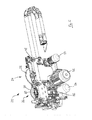
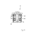
- FIG. 5 the saw carriage 20 is shown in more detail. It can be seen rollers 48 for supporting the saw carriage 20 on the rails, not shown, a drive motor 50 for moving the saw carriage 20, a drive motor 52, the Main saw blade 28 drives, and a drive motor 54 which drives the scoring saw blade 30 via a belt 56.
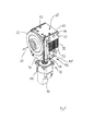
- FIGS. 6 and 7 show the scoring saw 26 more in detail. It recognizes linear guides 58, in which a carriage 60 is held vertically displaceable.
- the carriage 60 is of a in the FIGS. 6 and 7 Not shown shaft passes through, which has a flange 62 for attachment of the scoring blade 30 at one end and a pulley 64 for the belt 56 at the other end.
- the height adjustment of the carriage 60 by means of a spindle drive 66.
- the exact structure of the carriage 60 of the scoring saw 26 will now be with reference to the FIGS. 8 to 14 explained.
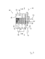
- the carriage 60 comprises a first bearing section 68, on which the shaft is mounted with the flange 62, and a second bearing section 70, on which in turn the first bearing section 68 is mounted in a manner to be shown in more detail.
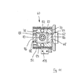
- the first bearing portion 68 may be formed in a direction orthogonal to the plane of the scoring blade 30 (in FIG FIG. 9 indicated by a dot-dashed line) relative to the second bearing portion 70, corresponding to the double arrow 32 in FIG FIG. 8 , Serves for this purpose an adjusting 72, which is arranged predominantly in the interior of the carriage 60 and therefore in the FIGS. 8 and 9 barely visible.
- the adjusting device 72 comprises a gear whose input shaft 74 is substantially vertical.
- the input shaft 74 is mounted on the second bearing portion 70 via annular ball bearings 76. That in the Figures 10 and 14 The upper end of the input shaft 74 has an eccentric section 78, which via a further annular ball bearing 80 in a circular recess a rectangular outer contour ( FIG. 11 ) having eccentric disc 82 engages. About inserted passages 84 is the eccentric disc 82 with pulled down portions 86 of the first bearing portion 68 coupled. The passages 84 can be adjusted by adjusting screws 88 (FIG. FIG. 12 ), which are screwed into the pulled-down portions 86, are acted upon, whereby indirectly also the eccentric disc 82 is applied and a possibly still existing game is eliminated.
- FIG. 8 It can be seen that the input shaft 74 is coupled to a drive motor 90, which is so far below the carriage 60 and therefore quite below the second bearing portion 70 is arranged.
- a special feature is the storage of the first bearing portion 68 on the second bearing portion 70: namely, this is done by lateral connecting plates 92, which are bolted to a first, in the figures, upper edge portion 94 with the first bearing portion 68, and with a second, in the figures lower edge portion 96 are screwed to the second bearing portion 70.
- the region of the connecting plates 92 located between the two edge regions 94 and 96 facing away from each other is weakened by a multiplicity of elongated recesses 98 extending substantially vertically.
- each connection plate 92 is formed by a plurality, for example, three individual layers, that is, so to speak, forms a sandwich, wherein each sandwich layer is formed by a relatively thick steel sheet.
- the recesses 98 are introduced, for example, by laser processing or water jet cutting. Between adjacent recesses 98 material bridges 100 are formed, which have resilient properties and in the direction of adjustability of the first bearing portion 68, ie in the direction of the double arrows 32, for example in FIG. 8 , Have a significantly lower rigidity than in any orthogonal direction thereto, so for example in the lateral direction.
- the connecting plates 92 also serve the exact guidance of the movable first bearing portion 68 relative to the second Bearing section 70:
- the first bearing section 68 has, on its outer side facing the connecting plates 92, a high-precision machined contact surface 102 which is provided with a guide surface 104 (FIG. FIG. 10 ) works together in a smooth manner.
- the scribing saw 26 further comprises an absolute measuring system 106, comprising inter alia a sensor 108 and a sensor surface 110, which is formed on the side of an end region of a rod 112 attached to the first bearing section 68 facing the sensor 108.
- the sensor 108 is attached to the second bearing portion 70.
- the sensor 108 detects the absolute size of the distance between the sensor 108 and the sensor surface 110 and provides corresponding signals of the control and regulating device 42.
- the adjustment of the scoring blade 30 in the direction of the double arrow 32 is as follows: First, the absolute position of the center plane of the scoring blade 30 is detected by the absolute measurement system 106, and in the control and regulating device 42 is calculated whether this position of the desired relative position of the scoring blade 30 to Main saw blade 28 corresponds. If this is not the case, is controlled by the control and regulating device 42 of the drive motor 90, whereby the input shaft 74 is rotated about its vertical axis in the illustrated installation position. As a result, the eccentric portion 78 is moved, which has a movement of the eccentric disc 82, among other things parallel to the direction of the double arrow 32 result.
- first bearing section 68 and the second bearing section 70 which comprise no material bridges 100 but, for example, one or more linear guides.
- a connection between the first bearing section 68 and the second bearing section 70 which comprise no material bridges 100 but, for example, one or more linear guides.
- a worm gear or something similar is conceivable. It is important that by the vertical arrangement of the input shaft 74 and the possible arrangement of the drive motor 90 below the carriage 60, the entire scoring saw 26 to the side so narrow builds that within the machine base 40 in FIG. 3 can perform vertical movement shown.
Landscapes
- Engineering & Computer Science (AREA)
- Mechanical Engineering (AREA)
- Life Sciences & Earth Sciences (AREA)
- Wood Science & Technology (AREA)
- Forests & Forestry (AREA)
- Sawing (AREA)
Applications Claiming Priority (1)
| Application Number | Priority Date | Filing Date | Title |
|---|---|---|---|
| DE201010041375 DE102010041375B4 (de) | 2010-09-24 | 2010-09-24 | Plattenaufteilanlage zum Aufteilen von plattenförmigen Werkstücken |
Publications (2)
| Publication Number | Publication Date |
|---|---|
| EP2433731A1 true EP2433731A1 (fr) | 2012-03-28 |
| EP2433731B1 EP2433731B1 (fr) | 2016-06-22 |
Family
ID=44654045
Family Applications (1)
| Application Number | Title | Priority Date | Filing Date |
|---|---|---|---|
| EP11180880.4A Active EP2433731B1 (fr) | 2010-09-24 | 2011-09-12 | Installation de répartition de plaques pour répartir des pièces en forme de plaques |
Country Status (2)
| Country | Link |
|---|---|
| EP (1) | EP2433731B1 (fr) |
| DE (1) | DE102010041375B4 (fr) |
Cited By (2)
| Publication number | Priority date | Publication date | Assignee | Title |
|---|---|---|---|---|
| WO2015018580A1 (fr) * | 2013-08-08 | 2015-02-12 | Holzma Plattenaufteiltechnik Gmbh | Installation de division de plaques |
| CN110586973A (zh) * | 2019-09-20 | 2019-12-20 | 牡丹江师范学院 | 一种金刚石齐头刀具 |
Citations (4)
| Publication number | Priority date | Publication date | Assignee | Title |
|---|---|---|---|---|
| EP0189095A1 (fr) * | 1985-01-19 | 1986-07-30 | REICH Spezialmaschinen GmbH | Dispositif pour l'incision de pièces à usiner |
| EP1066906A2 (fr) * | 1999-07-07 | 2001-01-10 | Selco Spa | Procédé pour mesurer des caractertéristiques liées à des lames de scies circulaires et dispositif d'alignement précise de lame de scie circulaire et la lame de scie à inciser |
| DE102006011131B3 (de) | 2006-03-10 | 2007-09-13 | Holzma Plattenaufteiltechnik Gmbh | Sägevorrichtung |
| EP2316601A1 (fr) * | 2009-11-03 | 2011-05-04 | Valter Naldi | Procédé et dispositif pour aligner des lames de scie |
Family Cites Families (1)
| Publication number | Priority date | Publication date | Assignee | Title |
|---|---|---|---|---|
| DE202007005609U1 (de) * | 2006-03-21 | 2007-08-16 | Panhans Maschinenbau Gmbh | Kreissägemaschine mit Antrieb über ein Winkelgetriebe |
-
2010
- 2010-09-24 DE DE201010041375 patent/DE102010041375B4/de active Active
-
2011
- 2011-09-12 EP EP11180880.4A patent/EP2433731B1/fr active Active
Patent Citations (4)
| Publication number | Priority date | Publication date | Assignee | Title |
|---|---|---|---|---|
| EP0189095A1 (fr) * | 1985-01-19 | 1986-07-30 | REICH Spezialmaschinen GmbH | Dispositif pour l'incision de pièces à usiner |
| EP1066906A2 (fr) * | 1999-07-07 | 2001-01-10 | Selco Spa | Procédé pour mesurer des caractertéristiques liées à des lames de scies circulaires et dispositif d'alignement précise de lame de scie circulaire et la lame de scie à inciser |
| DE102006011131B3 (de) | 2006-03-10 | 2007-09-13 | Holzma Plattenaufteiltechnik Gmbh | Sägevorrichtung |
| EP2316601A1 (fr) * | 2009-11-03 | 2011-05-04 | Valter Naldi | Procédé et dispositif pour aligner des lames de scie |
Cited By (2)
| Publication number | Priority date | Publication date | Assignee | Title |
|---|---|---|---|---|
| WO2015018580A1 (fr) * | 2013-08-08 | 2015-02-12 | Holzma Plattenaufteiltechnik Gmbh | Installation de division de plaques |
| CN110586973A (zh) * | 2019-09-20 | 2019-12-20 | 牡丹江师范学院 | 一种金刚石齐头刀具 |
Also Published As
| Publication number | Publication date |
|---|---|
| DE102010041375B4 (de) | 2012-12-27 |
| DE102010041375A1 (de) | 2012-03-29 |
| EP2433731B1 (fr) | 2016-06-22 |
Similar Documents
| Publication | Publication Date | Title |
|---|---|---|
| DE102008032159B4 (de) | Plattenaufteilanlage für großformatige plattenförmige Werkstücke, insbesondere Möbelteile | |
| EP2127829A1 (fr) | Installation de distribution de plaques | |
| EP0189095B1 (fr) | Dispositif pour l'incision de pièces à usiner | |
| EP1810769B1 (fr) | Machine à usiner des panneaux avec unité de sciage et procédé de fonctionnement d'une telle machine | |
| EP1837141B1 (fr) | Dispositif de coupe | |
| EP1782931B1 (fr) | Machine à fraiser les bords | |
| EP0382877B1 (fr) | Dispositif pour dégauchir et réduire l'épaisseur de pièces de bois d'une taille quelconque, en particulier des pièces minces et courtes | |
| EP2433731B1 (fr) | Installation de répartition de plaques pour répartir des pièces en forme de plaques | |
| EP2366512B1 (fr) | Dispositif de découpe de plaques | |
| DE2636529A1 (de) | Saegemaschine fuer oberflaechenbeschichtete platten | |
| EP3006173A1 (fr) | Procédé et dispositif de division d'un déchet formé pendant un procédé de délignage d'une pièce en forme de plaque | |
| EP3380287A1 (fr) | Procédé d'usinage d'une pièce de forme plate, et installation de division de plaques destinée à la mise en oeuvre du procédé | |
| DE102013206159A1 (de) | Plattenaufteilanlage | |
| EP0636061B1 (fr) | Dispositif de decoupage de lamelles dans du bois equarri, sans formation de copeaux | |
| DE202007010479U1 (de) | Plattenaufteilsäge | |
| EP2193894B1 (fr) | Procédé de sciage d'au moins une plaque | |
| DE102017011825B4 (de) | Verfahren zum Auftrennen länglicher Werkstücke aus Holz, Kunststoff und dergleichen in Lamellen sowie Bearbeitungsmaschine zur Durchführung eines solchen Verfahrens | |
| DE2602921C3 (de) | Verfahren zum Trennen von Möbelbauplatten sowie Einrichtung zur Durchführung dieses Verfahrens | |
| EP2149416A2 (fr) | Scie à barres de pression | |
| DE19828749B4 (de) | Unterflursägemaschine | |
| EP2808138A1 (fr) | Agencement de dispositif de coupe et procédé de coupe | |
| DE3244450A1 (de) | Kreissaegemaschine | |
| EP1439044B1 (fr) | Une machine outil à bois avec un système de butée | |
| DE1802679A1 (de) | Vorrichtung zum Schneiden tafelfoermigen Materials,z.B. von Sperrholz | |
| DE102019002689A1 (de) | Verfahren zur Herstellung einer Längsnut mit Hinterschneidung in einem Werkstück aus Holz, Kunststoff und dergleichen sowie Maschine zur Durchführung eines solchen Verfahrens |
Legal Events
| Date | Code | Title | Description |
|---|---|---|---|
| PUAI | Public reference made under article 153(3) epc to a published international application that has entered the european phase |
Free format text: ORIGINAL CODE: 0009012 |
|
| AK | Designated contracting states |
Kind code of ref document: A1 Designated state(s): AL AT BE BG CH CY CZ DE DK EE ES FI FR GB GR HR HU IE IS IT LI LT LU LV MC MK MT NL NO PL PT RO RS SE SI SK SM TR |
|
| AX | Request for extension of the european patent |
Extension state: BA ME |
|
| 17P | Request for examination filed |
Effective date: 20120816 |
|
| 17Q | First examination report despatched |
Effective date: 20150126 |
|
| GRAP | Despatch of communication of intention to grant a patent |
Free format text: ORIGINAL CODE: EPIDOSNIGR1 |
|
| INTG | Intention to grant announced |
Effective date: 20160208 |
|
| RIN1 | Information on inventor provided before grant (corrected) |
Inventor name: BLAICH, MARKUS Inventor name: REINAUER, JOSEF |
|
| GRAS | Grant fee paid |
Free format text: ORIGINAL CODE: EPIDOSNIGR3 |
|
| GRAA | (expected) grant |
Free format text: ORIGINAL CODE: 0009210 |
|
| AK | Designated contracting states |
Kind code of ref document: B1 Designated state(s): AL AT BE BG CH CY CZ DE DK EE ES FI FR GB GR HR HU IE IS IT LI LT LU LV MC MK MT NL NO PL PT RO RS SE SI SK SM TR |
|
| REG | Reference to a national code |
Ref country code: GB Ref legal event code: FG4D Free format text: NOT ENGLISH |
|
| REG | Reference to a national code |
Ref country code: CH Ref legal event code: EP |
|
| REG | Reference to a national code |
Ref country code: IE Ref legal event code: FG4D Free format text: LANGUAGE OF EP DOCUMENT: GERMAN |
|
| REG | Reference to a national code |
Ref country code: AT Ref legal event code: REF Ref document number: 807372 Country of ref document: AT Kind code of ref document: T Effective date: 20160715 |
|
| REG | Reference to a national code |
Ref country code: DE Ref legal event code: R096 Ref document number: 502011009994 Country of ref document: DE |
|
| REG | Reference to a national code |
Ref country code: LT Ref legal event code: MG4D |
|
| REG | Reference to a national code |
Ref country code: NL Ref legal event code: MP Effective date: 20160622 |
|
| PG25 | Lapsed in a contracting state [announced via postgrant information from national office to epo] |
Ref country code: NO Free format text: LAPSE BECAUSE OF FAILURE TO SUBMIT A TRANSLATION OF THE DESCRIPTION OR TO PAY THE FEE WITHIN THE PRESCRIBED TIME-LIMIT Effective date: 20160922 Ref country code: LT Free format text: LAPSE BECAUSE OF FAILURE TO SUBMIT A TRANSLATION OF THE DESCRIPTION OR TO PAY THE FEE WITHIN THE PRESCRIBED TIME-LIMIT Effective date: 20160622 Ref country code: FI Free format text: LAPSE BECAUSE OF FAILURE TO SUBMIT A TRANSLATION OF THE DESCRIPTION OR TO PAY THE FEE WITHIN THE PRESCRIBED TIME-LIMIT Effective date: 20160622 |
|
| PG25 | Lapsed in a contracting state [announced via postgrant information from national office to epo] |
Ref country code: GR Free format text: LAPSE BECAUSE OF FAILURE TO SUBMIT A TRANSLATION OF THE DESCRIPTION OR TO PAY THE FEE WITHIN THE PRESCRIBED TIME-LIMIT Effective date: 20160923 Ref country code: NL Free format text: LAPSE BECAUSE OF FAILURE TO SUBMIT A TRANSLATION OF THE DESCRIPTION OR TO PAY THE FEE WITHIN THE PRESCRIBED TIME-LIMIT Effective date: 20160622 Ref country code: HR Free format text: LAPSE BECAUSE OF FAILURE TO SUBMIT A TRANSLATION OF THE DESCRIPTION OR TO PAY THE FEE WITHIN THE PRESCRIBED TIME-LIMIT Effective date: 20160622 Ref country code: SE Free format text: LAPSE BECAUSE OF FAILURE TO SUBMIT A TRANSLATION OF THE DESCRIPTION OR TO PAY THE FEE WITHIN THE PRESCRIBED TIME-LIMIT Effective date: 20160622 Ref country code: RS Free format text: LAPSE BECAUSE OF FAILURE TO SUBMIT A TRANSLATION OF THE DESCRIPTION OR TO PAY THE FEE WITHIN THE PRESCRIBED TIME-LIMIT Effective date: 20160622 Ref country code: LV Free format text: LAPSE BECAUSE OF FAILURE TO SUBMIT A TRANSLATION OF THE DESCRIPTION OR TO PAY THE FEE WITHIN THE PRESCRIBED TIME-LIMIT Effective date: 20160622 |
|
| PG25 | Lapsed in a contracting state [announced via postgrant information from national office to epo] |
Ref country code: EE Free format text: LAPSE BECAUSE OF FAILURE TO SUBMIT A TRANSLATION OF THE DESCRIPTION OR TO PAY THE FEE WITHIN THE PRESCRIBED TIME-LIMIT Effective date: 20160622 Ref country code: RO Free format text: LAPSE BECAUSE OF FAILURE TO SUBMIT A TRANSLATION OF THE DESCRIPTION OR TO PAY THE FEE WITHIN THE PRESCRIBED TIME-LIMIT Effective date: 20160622 Ref country code: IS Free format text: LAPSE BECAUSE OF FAILURE TO SUBMIT A TRANSLATION OF THE DESCRIPTION OR TO PAY THE FEE WITHIN THE PRESCRIBED TIME-LIMIT Effective date: 20161022 Ref country code: CZ Free format text: LAPSE BECAUSE OF FAILURE TO SUBMIT A TRANSLATION OF THE DESCRIPTION OR TO PAY THE FEE WITHIN THE PRESCRIBED TIME-LIMIT Effective date: 20160622 Ref country code: SK Free format text: LAPSE BECAUSE OF FAILURE TO SUBMIT A TRANSLATION OF THE DESCRIPTION OR TO PAY THE FEE WITHIN THE PRESCRIBED TIME-LIMIT Effective date: 20160622 |
|
| PG25 | Lapsed in a contracting state [announced via postgrant information from national office to epo] |
Ref country code: SM Free format text: LAPSE BECAUSE OF FAILURE TO SUBMIT A TRANSLATION OF THE DESCRIPTION OR TO PAY THE FEE WITHIN THE PRESCRIBED TIME-LIMIT Effective date: 20160622 Ref country code: BE Free format text: LAPSE BECAUSE OF NON-PAYMENT OF DUE FEES Effective date: 20160930 Ref country code: PT Free format text: LAPSE BECAUSE OF FAILURE TO SUBMIT A TRANSLATION OF THE DESCRIPTION OR TO PAY THE FEE WITHIN THE PRESCRIBED TIME-LIMIT Effective date: 20161024 Ref country code: PL Free format text: LAPSE BECAUSE OF FAILURE TO SUBMIT A TRANSLATION OF THE DESCRIPTION OR TO PAY THE FEE WITHIN THE PRESCRIBED TIME-LIMIT Effective date: 20160622 Ref country code: ES Free format text: LAPSE BECAUSE OF FAILURE TO SUBMIT A TRANSLATION OF THE DESCRIPTION OR TO PAY THE FEE WITHIN THE PRESCRIBED TIME-LIMIT Effective date: 20160622 |
|
| REG | Reference to a national code |
Ref country code: DE Ref legal event code: R097 Ref document number: 502011009994 Country of ref document: DE |
|
| PG25 | Lapsed in a contracting state [announced via postgrant information from national office to epo] |
Ref country code: MC Free format text: LAPSE BECAUSE OF FAILURE TO SUBMIT A TRANSLATION OF THE DESCRIPTION OR TO PAY THE FEE WITHIN THE PRESCRIBED TIME-LIMIT Effective date: 20160622 |
|
| PLBE | No opposition filed within time limit |
Free format text: ORIGINAL CODE: 0009261 |
|
| REG | Reference to a national code |
Ref country code: CH Ref legal event code: PL |
|
| STAA | Information on the status of an ep patent application or granted ep patent |
Free format text: STATUS: NO OPPOSITION FILED WITHIN TIME LIMIT |
|
| GBPC | Gb: european patent ceased through non-payment of renewal fee |
Effective date: 20160922 |
|
| 26N | No opposition filed |
Effective date: 20170323 |
|
| PG25 | Lapsed in a contracting state [announced via postgrant information from national office to epo] |
Ref country code: DK Free format text: LAPSE BECAUSE OF FAILURE TO SUBMIT A TRANSLATION OF THE DESCRIPTION OR TO PAY THE FEE WITHIN THE PRESCRIBED TIME-LIMIT Effective date: 20160622 |
|
| REG | Reference to a national code |
Ref country code: IE Ref legal event code: MM4A |
|
| REG | Reference to a national code |
Ref country code: FR Ref legal event code: ST Effective date: 20170531 |
|
| PG25 | Lapsed in a contracting state [announced via postgrant information from national office to epo] |
Ref country code: IE Free format text: LAPSE BECAUSE OF NON-PAYMENT OF DUE FEES Effective date: 20160912 Ref country code: GB Free format text: LAPSE BECAUSE OF NON-PAYMENT OF DUE FEES Effective date: 20160922 Ref country code: FR Free format text: LAPSE BECAUSE OF NON-PAYMENT OF DUE FEES Effective date: 20160930 Ref country code: LI Free format text: LAPSE BECAUSE OF NON-PAYMENT OF DUE FEES Effective date: 20160930 Ref country code: CH Free format text: LAPSE BECAUSE OF NON-PAYMENT OF DUE FEES Effective date: 20160930 |
|
| PG25 | Lapsed in a contracting state [announced via postgrant information from national office to epo] |
Ref country code: SI Free format text: LAPSE BECAUSE OF FAILURE TO SUBMIT A TRANSLATION OF THE DESCRIPTION OR TO PAY THE FEE WITHIN THE PRESCRIBED TIME-LIMIT Effective date: 20160622 Ref country code: LU Free format text: LAPSE BECAUSE OF NON-PAYMENT OF DUE FEES Effective date: 20160912 |
|
| REG | Reference to a national code |
Ref country code: BE Ref legal event code: MM Effective date: 20160930 |
|
| PG25 | Lapsed in a contracting state [announced via postgrant information from national office to epo] |
Ref country code: HU Free format text: LAPSE BECAUSE OF FAILURE TO SUBMIT A TRANSLATION OF THE DESCRIPTION OR TO PAY THE FEE WITHIN THE PRESCRIBED TIME-LIMIT; INVALID AB INITIO Effective date: 20110912 Ref country code: CY Free format text: LAPSE BECAUSE OF FAILURE TO SUBMIT A TRANSLATION OF THE DESCRIPTION OR TO PAY THE FEE WITHIN THE PRESCRIBED TIME-LIMIT Effective date: 20160622 |
|
| PG25 | Lapsed in a contracting state [announced via postgrant information from national office to epo] |
Ref country code: MT Free format text: LAPSE BECAUSE OF FAILURE TO SUBMIT A TRANSLATION OF THE DESCRIPTION OR TO PAY THE FEE WITHIN THE PRESCRIBED TIME-LIMIT Effective date: 20160622 Ref country code: TR Free format text: LAPSE BECAUSE OF FAILURE TO SUBMIT A TRANSLATION OF THE DESCRIPTION OR TO PAY THE FEE WITHIN THE PRESCRIBED TIME-LIMIT Effective date: 20160622 Ref country code: MK Free format text: LAPSE BECAUSE OF FAILURE TO SUBMIT A TRANSLATION OF THE DESCRIPTION OR TO PAY THE FEE WITHIN THE PRESCRIBED TIME-LIMIT Effective date: 20160622 |
|
| PG25 | Lapsed in a contracting state [announced via postgrant information from national office to epo] |
Ref country code: BG Free format text: LAPSE BECAUSE OF FAILURE TO SUBMIT A TRANSLATION OF THE DESCRIPTION OR TO PAY THE FEE WITHIN THE PRESCRIBED TIME-LIMIT Effective date: 20160622 |
|
| PG25 | Lapsed in a contracting state [announced via postgrant information from national office to epo] |
Ref country code: AL Free format text: LAPSE BECAUSE OF FAILURE TO SUBMIT A TRANSLATION OF THE DESCRIPTION OR TO PAY THE FEE WITHIN THE PRESCRIBED TIME-LIMIT Effective date: 20160622 |
|
| P01 | Opt-out of the competence of the unified patent court (upc) registered |
Effective date: 20230529 |
|
| PGFP | Annual fee paid to national office [announced via postgrant information from national office to epo] |
Ref country code: AT Payment date: 20230915 Year of fee payment: 13 |
|
| PGFP | Annual fee paid to national office [announced via postgrant information from national office to epo] |
Ref country code: IT Payment date: 20230929 Year of fee payment: 13 Ref country code: DE Payment date: 20231117 Year of fee payment: 13 |