EP2433731A1 - Board partitioning assembly for partitioning plate-shaped work pieces - Google Patents
Board partitioning assembly for partitioning plate-shaped work pieces Download PDFInfo
- Publication number
- EP2433731A1 EP2433731A1 EP11180880A EP11180880A EP2433731A1 EP 2433731 A1 EP2433731 A1 EP 2433731A1 EP 11180880 A EP11180880 A EP 11180880A EP 11180880 A EP11180880 A EP 11180880A EP 2433731 A1 EP2433731 A1 EP 2433731A1
- Authority
- EP
- European Patent Office
- Prior art keywords
- saw
- scoring
- bearing portion
- bearing
- bearing section
- Prior art date
- Legal status (The legal status is an assumption and is not a legal conclusion. Google has not performed a legal analysis and makes no representation as to the accuracy of the status listed.)
- Granted
Links
- 238000000638 solvent extraction Methods 0.000 title 2
- 238000000034 method Methods 0.000 claims abstract description 4
- 238000009434 installation Methods 0.000 claims description 12
- 239000000463 material Substances 0.000 claims description 7
- 230000001105 regulatory effect Effects 0.000 claims description 7
- 238000004519 manufacturing process Methods 0.000 claims description 4
- 238000003754 machining Methods 0.000 claims description 2
- 239000013013 elastic material Substances 0.000 claims 1
- 239000011248 coating agent Substances 0.000 description 2
- 238000000576 coating method Methods 0.000 description 2
- 238000000926 separation method Methods 0.000 description 2
- 229910000831 Steel Inorganic materials 0.000 description 1
- 230000008878 coupling Effects 0.000 description 1
- 238000010168 coupling process Methods 0.000 description 1
- 238000005859 coupling reaction Methods 0.000 description 1
- 238000005520 cutting process Methods 0.000 description 1
- 238000013461 design Methods 0.000 description 1
- 238000011161 development Methods 0.000 description 1
- 230000018109 developmental process Effects 0.000 description 1
- 238000005516 engineering process Methods 0.000 description 1
- 238000005259 measurement Methods 0.000 description 1
- 238000012545 processing Methods 0.000 description 1
- 239000012858 resilient material Substances 0.000 description 1
- 239000010959 steel Substances 0.000 description 1
- 238000003860 storage Methods 0.000 description 1
- XLYOFNOQVPJJNP-UHFFFAOYSA-N water Substances O XLYOFNOQVPJJNP-UHFFFAOYSA-N 0.000 description 1
Images


Classifications
-
- B—PERFORMING OPERATIONS; TRANSPORTING
- B23—MACHINE TOOLS; METAL-WORKING NOT OTHERWISE PROVIDED FOR
- B23D—PLANING; SLOTTING; SHEARING; BROACHING; SAWING; FILING; SCRAPING; LIKE OPERATIONS FOR WORKING METAL BY REMOVING MATERIAL, NOT OTHERWISE PROVIDED FOR
- B23D45/00—Sawing machines or sawing devices with circular saw blades or with friction saw discs
- B23D45/10—Sawing machines or sawing devices with circular saw blades or with friction saw discs with a plurality of circular saw blades
- B23D45/105—Sawing machines or sawing devices with circular saw blades or with friction saw discs with a plurality of circular saw blades operating within the same plane
-
- B—PERFORMING OPERATIONS; TRANSPORTING
- B23—MACHINE TOOLS; METAL-WORKING NOT OTHERWISE PROVIDED FOR
- B23D—PLANING; SLOTTING; SHEARING; BROACHING; SAWING; FILING; SCRAPING; LIKE OPERATIONS FOR WORKING METAL BY REMOVING MATERIAL, NOT OTHERWISE PROVIDED FOR
- B23D59/00—Accessories specially designed for sawing machines or sawing devices
- B23D59/001—Measuring or control devices, e.g. for automatic control of work feed pressure on band saw blade
- B23D59/002—Measuring or control devices, e.g. for automatic control of work feed pressure on band saw blade for the position of the saw blade
-
- B—PERFORMING OPERATIONS; TRANSPORTING
- B27—WORKING OR PRESERVING WOOD OR SIMILAR MATERIAL; NAILING OR STAPLING MACHINES IN GENERAL
- B27G—ACCESSORY MACHINES OR APPARATUS FOR WORKING WOOD OR SIMILAR MATERIALS; TOOLS FOR WORKING WOOD OR SIMILAR MATERIALS; SAFETY DEVICES FOR WOOD WORKING MACHINES OR TOOLS
- B27G19/00—Safety guards or devices specially adapted for wood saws; Auxiliary devices facilitating proper operation of wood saws
- B27G19/10—Measures preventing splintering of sawn portions of wood
Abstract
Description
Die Erfindung betrifft eine Plattenaufteilanlage zum Aufteilen von plattenförmigen Werkstücken nach dem Oberbegriff des Anspruchs 1.The invention relates to a panel dividing system for dividing plate-shaped workpieces according to the preamble of
Die
Bei der Herstellung der Vorritzfuge ist es wichtig, dass diese mit der später eingebrachten Trennfuge möglichst exakt fluchtet. Daher wird in der
Aufgabe der vorliegenden Erfindung ist es, eine Vorrichtung zu schaffen, bei der auch bei dicken Werkstückstapeln die Vorteile der Verwendung einer Vorritzsäge genutzt werden können.The object of the present invention is to provide a device in which the advantages of using a scoring saw can be used even with thick workpiece stacks.
Diese Aufgabe wird durch eine Plattenaufteilanlage mit den Merkmalen des Anspruchs 1 gelöst. Vorteilhafte Weiterbildungen der Erfindung sind in Unteransprüchen angegeben, wobei bereits hier darauf hingewiesen wird, dass die Merkmale der Unteransprüche auch selbstständig bei einer Plattenaufteilanlage mit Vorritzsäge und Hauptsäge als erfinderisch angesehen werden. Für die Erfindung wichtige Merkmale können darüber hinaus auch der nachfolgenden Beschreibung und der Zeichnung entnommen werden, wobei die Merkmale sowohl in Alleinstellung als auch in unterschiedlichen Kombinationen für die Erfindung wichtig sein können.This object is achieved by a panel splitter with the features of
Die erfindungsgemäße Plattenaufteilanlage hat den Vorteil, dass ein Exzentergetriebe konstruktiv sehr einfach und selbsthemmend ist und eine präzise Justierung des Vorritzsägeblatts orthogonal zu seiner Blattebene erlaubt. Außerdem baut ein solches Exzentergetriebe sehr klein und schmal, wodurch insbesondere zu den Seiten hin kleine Abmessungen der Vorritzsäge erreicht werden.The panel dividing system according to the invention has the advantage that an eccentric gear is structurally very simple and self-locking and allows a precise adjustment of the scoring blade orthogonal to its leaf level. In addition, such an eccentric gear builds very small and narrow, which in particular to the sides towards small dimensions of the scoring saw can be achieved.
Dies führt dazu, dass der Sägewagen das Vorritzsägeblatt bis in einen seitlich von einem Bearbeitungstisch, auf dem die aufzuteilenden Platten liegen, vorhandenen Maschinenfuß bewegen kann, wo dann das Vorritzsägeblatt durch eine entsprechende Einrichtung vertikal bewegt werden kann, um einen seitlichen Rand des Werkstückstapels, beispielsweise von Küchenarbeitsplatten, vorzuritzen. Dadurch, dass die gesamte Vorritzsäge einschließlich ihrer Verstelleinrichtung so schmal baut, findet sie für den gerade beschriebenen Anwendungsfall auch in einem schmalen Maschinenfuß ausreichend Platz, um die besagte Vertikalbewegung ausführen zu können. Dies wird auch als "vertikales Vorritzen" bezeichnet.The result of this is that the saw carriage feeds the scoring saw blade into a machine base present on the side of a machining table on which the boards to be split are located can move, where then the scoring saw blade can be moved vertically by a corresponding device to pre-scrape a side edge of the workpiece stack, such as kitchen worktops. Due to the fact that the entire scoring saw, including its adjusting device, builds so narrowly, it finds sufficient space for the application just described, even in a narrow machine foot, in order to be able to carry out said vertical movement. This is also referred to as "vertical scribing".
Eine vertikale Eingangswelle verstärkt diese Vorteile nochmals.A vertical input shaft reinforces these advantages again.
Eine Verstellschraube im ersten Lagerabschnitt, die die Exzenterscheibe mittelbar beaufschlagt, gestattet eine spielfreie Koppelung des ersten Lagerabschnitts an die Exzenterscheibe, erhöht also nochmals die Justiergenauigkeit.An adjusting screw in the first bearing section, which acts indirectly on the eccentric disc, allows a play-free coupling of the first bearing section to the eccentric disc, so again increases the alignment accuracy.
Ein unterhalb vom zweiten Lagerabschnitt angeordneter Antriebsmotor sorgt für eine weiterhin sehr schmale Ausführung der Vorritzsäge mit den bereits oben genannten Vorteilen.A drive motor arranged below the second bearing section ensures a further very narrow design of the scoring saw with the advantages already mentioned above.
Wenn der erste Lagerabschnitt an dem zweiten Lagerabschnitt mittels mindestens einer Linearführung gelagert ist, baut die Vorrichtung besonders preiswert.When the first bearing portion is mounted on the second bearing portion by means of at least one linear guide, the device is particularly inexpensive.
Eine Mehrzahl federelastischer Materialbrücken zur Lagerung des ersten Lagerabschnitts sorgt für Spielfreiheit und konstruktive Robustheit.A plurality of resilient material bridges for supporting the first bearing section provides freedom from play and constructive robustness.
Unterschiedliche Steifigkeiten der Materialbrücken in Bewegungsrichtung des ersten Lagerabschnitts und quer hierzu sorgen für eine präzise Positionierung des ersten Lagerabschnitts.Different stiffnesses of the material bridges in the direction of movement of the first bearing section and transversely thereto ensure precise positioning of the first bearing section.
Die Verwendung einer Verbindungsplatte zur Herstellung der Materialbrücken ist fertigungstechnisch einfach, reduziert also die Herstellkosten.The use of a connection plate for the production of material bridges is simple in terms of production technology, thus reducing the production costs.
Die erfindungsgemäß vorgesehene Kontaktfläche, die an einer Führungsfläche anliegt, führt zu einer exakten seitlichen Positionierung und damit zu einem besonders guten Arbeitsergebnis.The inventively provided contact surface, which bears against a guide surface, leads to an exact lateral positioning and thus to a particularly good work result.
Dies ist besonders einfach zu realisieren, wenn Kontaktfläche und Führungsfläche am ersten Lagerabschnitt beziehungsweise der Verbindungsplatte vorhanden sind.This is particularly easy to implement when the contact surface and guide surface on the first bearing portion or the connecting plate are present.
Ein Absolutmesssystem stellt Signale bereit, die einer Steuerund Regeleinrichtung der Plattenaufteilanlage zu jedem Zeitpunkt, auch unmittelbar nach dem Start der Plattenaufteilanlage, die aktuelle Position des Vorritzsägeblatts anzeigt. Selbst nach einem Werkzeugwechsel ist bei vorhandenen Werkzeugdaten in einer Werkzeugdatenbank eine Neujustierung von Hand daher nicht erforderlich.An absolute measuring system provides signals which indicate to a control and regulating device of the panel dividing installation at any time, also immediately after the start of the panel dividing installation, the current position of the scoring saw blade. Even after a tool change, manual readjustment by hand is therefore not required with existing tool data in a tool database.
Ein solches Absolutmesssystem ist durch einen Sensor, der mit einer Sensorfläche zusammenwirkt, besonders einfach und robust zu realisieren.Such an absolute measuring system is particularly simple and robust to implement by a sensor that interacts with a sensor surface.
Nachfolgend wird eine Ausführungsform der Erfindung beispielhaft erläutert. In der Zeichnung zeigen:
Figur 1- eine Draufsicht auf eine Plattenaufteilanlage mit einem Sägewagen mit einer Hauptsäge und einer Vorritzsäge;
- Figur 2
- eine schematische Vorderansicht auf den Sägewagen von
Figur 1 - Figur 3
- eine Darstellung ähnlich
Figur 2 bei einem seitlichen vertikalen Vorritzvorgang; Figur 4- eine Darstellung ähnlich
Figur 2 bei einem normalen Sägevorgang nach dem inFigur 3 dargestellten Schritt; - Figur 5
- eine perspektivische Darstellung des Sägewagens von
Figur 1 - Figur 6
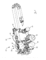
- eine perspektivische Darstellung der Vorritzsäge von
Figur 1 - Figur 7
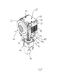
- eine perspektivische Darstellung der Vorritzsäge von
Figur 1 - Figur 8
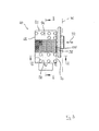
- eine perspektivische Darstellung eines ersten und eines zweiten Lagerabschnitts der Vorritzsäge der
Figuren 6 und7 ; - Figur 9
- eine Seitenansicht der Lagerabschnitte von
Figur 8 ; Figur 10- einen Schnitt längs der Linie X-X von
Figur 9 ; - Figur 11
- einen Schnitt längs der Linie XI-XI von
Figur 9 ; Figur 12- eine Vorderansicht der Lagerabschnitte von
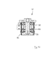
Figur 8 ; - Figur 13
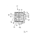
- einen Schnitt längs der Linie XIII-XIII von
Figur 12 Figur 14- einen Schnitt längs der Linie XIV-XIV von
Figur 12
- FIG. 1
- a plan view of a Plattenaufteilanlage with a saw carriage with a main saw and a scoring saw;
- FIG. 2
- a schematic front view of the saw carriage of
FIG. 1 in a normal scoring operation; - FIG. 3
- a representation similar
FIG. 2 in a lateral vertical scoring process; - FIG. 4
- a representation similar
FIG. 2 in a normal sawing after the inFIG. 3 illustrated step; - FIG. 5
- a perspective view of the saw carriage of
FIG. 1 from diagonally behind; - FIG. 6
- a perspective view of the scoring saw of
FIG. 1 from diagonally forward; - FIG. 7
- a perspective view of the scoring saw of
FIG. 1 from diagonally behind; - FIG. 8
- a perspective view of a first and a second bearing portion of the scoring saw
FIGS. 6 and7 ; - FIG. 9
- a side view of the bearing sections of
FIG. 8 ; - FIG. 10
- a section along the line XX of
FIG. 9 ; - FIG. 11
- a section along the line XI-XI of
FIG. 9 ; - FIG. 12
- a front view of the bearing sections of
FIG. 8 ; - FIG. 13
- a section along the line XIII-XIII of
FIG. 12 ; and - FIG. 14
- a section along the line XIV-XIV of
FIG. 12 ,
Eine Plattenaufteilanlage trägt in
In
Zwei verschiedene Arten der Anwendung der Plattenaufteilanlage 10 sind in den
In
Die
Der Schlitten 60 umfasst einen ersten Lagerabschnitt 68, an dem die Welle mit dem Flansch 62 gelagert ist, und einen zweiten Lagerabschnitt 70, an dem wiederum der erste Lagerabschnitt 68 auf noch genauer darzustellende Art und Weise gelagert ist. Dabei kann der erste Lagerabschnitt 68 in einer Richtung orthogonal zur Ebene des Vorritzsägeblatts 30 (in
Wie beispielsweise aus
Eine Besonderheit stellt die Lagerung des ersten Lagerabschnitts 68 am zweiten Lagerabschnitt 70 dar: Diese erfolgt nämlich durch seitliche Verbindungsplatten 92, die mit einem ersten, in den Figuren oberen Randbereich 94 mit dem ersten Lagerabschnitt 68 verschraubt sind, und mit einem zweiten, in den Figuren unteren Randabschnitt 96 mit dem zweiten Lagerabschnitt 70 verschraubt sind. Der zwischen den beiden voneinander abgewandten Randbereichen 94 und 96 gelegene Bereich der Verbindungsplatten 92 ist durch eine Vielzahl von sich im Wesentlichen vertikal erstreckenden länglichen Ausnehmungen 98 geschwächt. Dabei sei an dieser Stelle darauf hingewiesen, dass jede Verbindungsplatte 92 durch mehrere, beispielsweise drei Einzelschichten gebildet wird, also sozusagen einen Sandwich bildet, wobei jede Sandwichschicht durch ein relativ dickes Stahlblech gebildet wird. Die Ausnehmungen 98 sind beispielsweise durch Laserbearbeitung oder Wasserstrahlschneiden eingebracht. Zwischen benachbarten Ausnehmungen 98 sind Materialbrücken 100 gebildet, die federelastische Eigenschaften aufweisen und in Richtung der Verstellbarkeit des ersten Lagerabschnitts 68, also in Richtung der Doppelpfeile 32 beispielsweise in
Die Verbindungsplatten 92 dienen auch der exakten Führung des beweglichen ersten Lagerabschnitts 68 relativ zum zweiten Lagerabschnitt 70: Hierzu verfügt der erste Lagerabschnitt 68 auf seiner den Verbindungsplatten 92 zugewandten Außenseite über eine hochpräzise bearbeitete Kontaktfläche 102, die mit einer am zweiten Randbereich 96 der Verbindungsplatten 92 vorhandenen Führungsfläche 104 (
Die Vorritzsäge 26 umfasst ferner ein Absolutmesssystem 106, umfassend unter anderem einen Sensor 108 und eine Sensorfläche 110, die auf der dem Sensor 108 zugewandten Seite eines Endbereichs eines am ersten Lagerabschnitt 68 befestigten Stabs 112 ausgebildet ist. Der Sensor 108 ist dagegen am zweiten Lagerabschnitt 70 befestigt. Der Sensor 108 erfasst die absolute Größe des Abstandes zwischen Sensor 108 und der Sensorfläche 110 und stellt entsprechende Signale der Steuerund Regeleinrichtung 42 bereit.The scribing saw 26 further comprises an
Die Verstellung des Vorritzsägeblatts 30 in Richtung des Doppelpfeils 32 geschieht folgendermaßen: Zunächst wird über das Absolutmesssystem 106 die absolute Lage der Mittelebene des Vorritzsägeblatts 30 erfasst, und in der Steuer- und Regeleinrichtung 42 wird errechnet, ob diese Lage der gewünschten Relativlage des Vorritzsägeblatts 30 zum Hauptsägeblatt 28 entspricht. Ist dies nicht der Fall, wird von der Steuer- und Regeleinrichtung 42 der Antriebsmotor 90 angesteuert, wodurch die Eingangswelle 74 um Ihre in der dargestellten Einbaulage vertikale Achse gedreht wird. Hierdurch wird auch der Exzenterabschnitt 78 bewegt, was eine Bewegung der Exzenterscheibe 82 unter anderem parallel zur Richtung des Doppelpfeils 32 zur Folge hat. Diese Bewegung der Exzenterscheibe 82 wird über die Passstege 84 und die herunter gezogenen Abschnitte 86 auf den ersten Lagerabschnitt 68 übertragen, wodurch die Ebene des Vorritzsägeblatts 30 sich orthogonal zu sich selbst verschiebt. Bei der Bewegung des ersten Lagerabschnitts 68 relativ zum zweiten Lagerabschnitt 70 werden die Materialbrücken 100 zwischen den Ausnehmungen 98 in den Verbindungsplatten 92 federelastisch verbogen.The adjustment of the
Es versteht sich an dieser Stelle, dass die erfindungsgemäßen Vorteile auch mit einer Verbindung zwischen erstem Lagerabschnitt 68 und zweitem Lagerabschnitt 70 erzielt werden können, die keine Materialbrücken 100, sondern beispielsweise eine oder mehrere Linearführungen umfassen. Auch ist anstelle eines Exzentergetriebes beispielsweise ein Schneckengetriebe oder etwas Ähnliches denkbar. Wichtig ist, dass durch die vertikale Anordnung der Eingangswelle 74 und die hierdurch mögliche Anordnung des Antriebsmotors 90 unterhalb des Schlittens 60 die gesamte Vorritzsäge 26 zur Seite hin so schmal baut, dass sie innerhalb des Maschinenfußes 40 die in
Claims (14)
Applications Claiming Priority (1)
| Application Number | Priority Date | Filing Date | Title |
|---|---|---|---|
| DE201010041375 DE102010041375B4 (en) | 2010-09-24 | 2010-09-24 | Panel dividing plant for dividing plate-shaped workpieces |
Publications (2)
| Publication Number | Publication Date |
|---|---|
| EP2433731A1 true EP2433731A1 (en) | 2012-03-28 |
| EP2433731B1 EP2433731B1 (en) | 2016-06-22 |
Family
ID=44654045
Family Applications (1)
| Application Number | Title | Priority Date | Filing Date |
|---|---|---|---|
| EP11180880.4A Active EP2433731B1 (en) | 2010-09-24 | 2011-09-12 | Board partitioning assembly for partitioning plate-shaped work pieces |
Country Status (2)
| Country | Link |
|---|---|
| EP (1) | EP2433731B1 (en) |
| DE (1) | DE102010041375B4 (en) |
Cited By (2)
| Publication number | Priority date | Publication date | Assignee | Title |
|---|---|---|---|---|
| WO2015018580A1 (en) * | 2013-08-08 | 2015-02-12 | Holzma Plattenaufteiltechnik Gmbh | Panel-dividing system |
| CN110586973A (en) * | 2019-09-20 | 2019-12-20 | 牡丹江师范学院 | Diamond flush cutter |
Citations (4)
| Publication number | Priority date | Publication date | Assignee | Title |
|---|---|---|---|---|
| EP0189095A1 (en) * | 1985-01-19 | 1986-07-30 | REICH Spezialmaschinen GmbH | Device for scoring work pieces |
| EP1066906A2 (en) * | 1999-07-07 | 2001-01-10 | Selco Spa | Method of measuring the characteristics of circular saws, and device for accurately aligning a circular saw and associated notching tool |
| DE102006011131B3 (en) | 2006-03-10 | 2007-09-13 | Holzma Plattenaufteiltechnik Gmbh | sawing |
| EP2316601A1 (en) * | 2009-11-03 | 2011-05-04 | Valter Naldi | Method and apparatus for saw blades alignment |
Family Cites Families (1)
| Publication number | Priority date | Publication date | Assignee | Title |
|---|---|---|---|---|
| DE202007005609U1 (en) * | 2006-03-21 | 2007-08-16 | Panhans Maschinenbau Gmbh | Circular saw machine used as a bench saw or panel saw comprises a motor shaft and a drive shaft coupled via an angular gear |
-
2010
- 2010-09-24 DE DE201010041375 patent/DE102010041375B4/en active Active
-
2011
- 2011-09-12 EP EP11180880.4A patent/EP2433731B1/en active Active
Patent Citations (4)
| Publication number | Priority date | Publication date | Assignee | Title |
|---|---|---|---|---|
| EP0189095A1 (en) * | 1985-01-19 | 1986-07-30 | REICH Spezialmaschinen GmbH | Device for scoring work pieces |
| EP1066906A2 (en) * | 1999-07-07 | 2001-01-10 | Selco Spa | Method of measuring the characteristics of circular saws, and device for accurately aligning a circular saw and associated notching tool |
| DE102006011131B3 (en) | 2006-03-10 | 2007-09-13 | Holzma Plattenaufteiltechnik Gmbh | sawing |
| EP2316601A1 (en) * | 2009-11-03 | 2011-05-04 | Valter Naldi | Method and apparatus for saw blades alignment |
Cited By (2)
| Publication number | Priority date | Publication date | Assignee | Title |
|---|---|---|---|---|
| WO2015018580A1 (en) * | 2013-08-08 | 2015-02-12 | Holzma Plattenaufteiltechnik Gmbh | Panel-dividing system |
| CN110586973A (en) * | 2019-09-20 | 2019-12-20 | 牡丹江师范学院 | Diamond flush cutter |
Also Published As
| Publication number | Publication date |
|---|---|
| EP2433731B1 (en) | 2016-06-22 |
| DE102010041375A1 (en) | 2012-03-29 |
| DE102010041375B4 (en) | 2012-12-27 |
Similar Documents
| Publication | Publication Date | Title |
|---|---|---|
| DE102008032159B4 (en) | Panel dividing system for large-format plate-shaped workpieces, in particular furniture parts | |
| EP2127829A1 (en) | Board separation assembly | |
| EP0189095B1 (en) | Device for scoring work pieces | |
| EP1810769B1 (en) | Panel working machine with a saw unit and method for operating such a machine | |
| EP1837141B1 (en) | Sawing device | |
| EP1782931B1 (en) | Edge milling machine | |
| EP0382877B1 (en) | Apparatus for smoothing and thicknessing wooden work pieces of any size, particularly short and thin pieces | |
| EP2433731B1 (en) | Board partitioning assembly for partitioning plate-shaped work pieces | |
| EP2366512B1 (en) | Board separation assembly | |
| DE2636529A1 (en) | Machine saw for veneered boards - has two circular saw blades moving in synchronism about fixed workpiece to avoid splitting | |
| EP3006173A1 (en) | Method and device for dividing up a waste piece formed during edge trimming of a panel-shaped workpiece | |
| EP3380287A1 (en) | Method for machining a plate-like workpiece, and plate dividing system for carrying out the method | |
| DE102013206159A1 (en) | Beamsaw | |
| EP0636061B1 (en) | Device for cutting sheets of wood off square timber without forming chips | |
| DE202007010479U1 (en) | Panel | |
| EP2193894B1 (en) | Method for sawing up at least one board | |
| DE102017011825B4 (en) | Method for cutting elongated workpieces made of wood, plastic and the like into lamellas and processing machine for carrying out such a method | |
| DE2602921C3 (en) | Method for separating furniture panels and device for carrying out this method | |
| EP2149416A2 (en) | Pressure bar saw | |
| DE19828749B4 (en) | Unterflursägemaschine | |
| EP2808138A1 (en) | Capping device assembly and method for capping | |
| DE3244450A1 (en) | Circular saw machine | |
| EP1439044B1 (en) | Wood working machine with a work stop system | |
| DE1802679A1 (en) | Apparatus for cutting sheet material, e.g. of plywood | |
| DE102019002689A1 (en) | Method for producing a longitudinal groove with an undercut in a workpiece made of wood, plastic and the like, as well as a machine for carrying out such a method |
Legal Events
| Date | Code | Title | Description |
|---|---|---|---|
| PUAI | Public reference made under article 153(3) epc to a published international application that has entered the european phase |
Free format text: ORIGINAL CODE: 0009012 |
|
| AK | Designated contracting states |
Kind code of ref document: A1 Designated state(s): AL AT BE BG CH CY CZ DE DK EE ES FI FR GB GR HR HU IE IS IT LI LT LU LV MC MK MT NL NO PL PT RO RS SE SI SK SM TR |
|
| AX | Request for extension of the european patent |
Extension state: BA ME |
|
| 17P | Request for examination filed |
Effective date: 20120816 |
|
| 17Q | First examination report despatched |
Effective date: 20150126 |
|
| GRAP | Despatch of communication of intention to grant a patent |
Free format text: ORIGINAL CODE: EPIDOSNIGR1 |
|
| INTG | Intention to grant announced |
Effective date: 20160208 |
|
| RIN1 | Information on inventor provided before grant (corrected) |
Inventor name: BLAICH, MARKUS Inventor name: REINAUER, JOSEF |
|
| GRAS | Grant fee paid |
Free format text: ORIGINAL CODE: EPIDOSNIGR3 |
|
| GRAA | (expected) grant |
Free format text: ORIGINAL CODE: 0009210 |
|
| AK | Designated contracting states |
Kind code of ref document: B1 Designated state(s): AL AT BE BG CH CY CZ DE DK EE ES FI FR GB GR HR HU IE IS IT LI LT LU LV MC MK MT NL NO PL PT RO RS SE SI SK SM TR |
|
| REG | Reference to a national code |
Ref country code: GB Ref legal event code: FG4D Free format text: NOT ENGLISH |
|
| REG | Reference to a national code |
Ref country code: CH Ref legal event code: EP |
|
| REG | Reference to a national code |
Ref country code: IE Ref legal event code: FG4D Free format text: LANGUAGE OF EP DOCUMENT: GERMAN |
|
| REG | Reference to a national code |
Ref country code: AT Ref legal event code: REF Ref document number: 807372 Country of ref document: AT Kind code of ref document: T Effective date: 20160715 |
|
| REG | Reference to a national code |
Ref country code: DE Ref legal event code: R096 Ref document number: 502011009994 Country of ref document: DE |
|
| REG | Reference to a national code |
Ref country code: LT Ref legal event code: MG4D |
|
| REG | Reference to a national code |
Ref country code: NL Ref legal event code: MP Effective date: 20160622 |
|
| PG25 | Lapsed in a contracting state [announced via postgrant information from national office to epo] |
Ref country code: NO Free format text: LAPSE BECAUSE OF FAILURE TO SUBMIT A TRANSLATION OF THE DESCRIPTION OR TO PAY THE FEE WITHIN THE PRESCRIBED TIME-LIMIT Effective date: 20160922 Ref country code: LT Free format text: LAPSE BECAUSE OF FAILURE TO SUBMIT A TRANSLATION OF THE DESCRIPTION OR TO PAY THE FEE WITHIN THE PRESCRIBED TIME-LIMIT Effective date: 20160622 Ref country code: FI Free format text: LAPSE BECAUSE OF FAILURE TO SUBMIT A TRANSLATION OF THE DESCRIPTION OR TO PAY THE FEE WITHIN THE PRESCRIBED TIME-LIMIT Effective date: 20160622 |
|
| PG25 | Lapsed in a contracting state [announced via postgrant information from national office to epo] |
Ref country code: GR Free format text: LAPSE BECAUSE OF FAILURE TO SUBMIT A TRANSLATION OF THE DESCRIPTION OR TO PAY THE FEE WITHIN THE PRESCRIBED TIME-LIMIT Effective date: 20160923 Ref country code: NL Free format text: LAPSE BECAUSE OF FAILURE TO SUBMIT A TRANSLATION OF THE DESCRIPTION OR TO PAY THE FEE WITHIN THE PRESCRIBED TIME-LIMIT Effective date: 20160622 Ref country code: HR Free format text: LAPSE BECAUSE OF FAILURE TO SUBMIT A TRANSLATION OF THE DESCRIPTION OR TO PAY THE FEE WITHIN THE PRESCRIBED TIME-LIMIT Effective date: 20160622 Ref country code: SE Free format text: LAPSE BECAUSE OF FAILURE TO SUBMIT A TRANSLATION OF THE DESCRIPTION OR TO PAY THE FEE WITHIN THE PRESCRIBED TIME-LIMIT Effective date: 20160622 Ref country code: RS Free format text: LAPSE BECAUSE OF FAILURE TO SUBMIT A TRANSLATION OF THE DESCRIPTION OR TO PAY THE FEE WITHIN THE PRESCRIBED TIME-LIMIT Effective date: 20160622 Ref country code: LV Free format text: LAPSE BECAUSE OF FAILURE TO SUBMIT A TRANSLATION OF THE DESCRIPTION OR TO PAY THE FEE WITHIN THE PRESCRIBED TIME-LIMIT Effective date: 20160622 |
|
| PG25 | Lapsed in a contracting state [announced via postgrant information from national office to epo] |
Ref country code: EE Free format text: LAPSE BECAUSE OF FAILURE TO SUBMIT A TRANSLATION OF THE DESCRIPTION OR TO PAY THE FEE WITHIN THE PRESCRIBED TIME-LIMIT Effective date: 20160622 Ref country code: RO Free format text: LAPSE BECAUSE OF FAILURE TO SUBMIT A TRANSLATION OF THE DESCRIPTION OR TO PAY THE FEE WITHIN THE PRESCRIBED TIME-LIMIT Effective date: 20160622 Ref country code: IS Free format text: LAPSE BECAUSE OF FAILURE TO SUBMIT A TRANSLATION OF THE DESCRIPTION OR TO PAY THE FEE WITHIN THE PRESCRIBED TIME-LIMIT Effective date: 20161022 Ref country code: CZ Free format text: LAPSE BECAUSE OF FAILURE TO SUBMIT A TRANSLATION OF THE DESCRIPTION OR TO PAY THE FEE WITHIN THE PRESCRIBED TIME-LIMIT Effective date: 20160622 Ref country code: SK Free format text: LAPSE BECAUSE OF FAILURE TO SUBMIT A TRANSLATION OF THE DESCRIPTION OR TO PAY THE FEE WITHIN THE PRESCRIBED TIME-LIMIT Effective date: 20160622 |
|
| PG25 | Lapsed in a contracting state [announced via postgrant information from national office to epo] |
Ref country code: SM Free format text: LAPSE BECAUSE OF FAILURE TO SUBMIT A TRANSLATION OF THE DESCRIPTION OR TO PAY THE FEE WITHIN THE PRESCRIBED TIME-LIMIT Effective date: 20160622 Ref country code: BE Free format text: LAPSE BECAUSE OF NON-PAYMENT OF DUE FEES Effective date: 20160930 Ref country code: PT Free format text: LAPSE BECAUSE OF FAILURE TO SUBMIT A TRANSLATION OF THE DESCRIPTION OR TO PAY THE FEE WITHIN THE PRESCRIBED TIME-LIMIT Effective date: 20161024 Ref country code: PL Free format text: LAPSE BECAUSE OF FAILURE TO SUBMIT A TRANSLATION OF THE DESCRIPTION OR TO PAY THE FEE WITHIN THE PRESCRIBED TIME-LIMIT Effective date: 20160622 Ref country code: ES Free format text: LAPSE BECAUSE OF FAILURE TO SUBMIT A TRANSLATION OF THE DESCRIPTION OR TO PAY THE FEE WITHIN THE PRESCRIBED TIME-LIMIT Effective date: 20160622 |
|
| REG | Reference to a national code |
Ref country code: DE Ref legal event code: R097 Ref document number: 502011009994 Country of ref document: DE |
|
| PG25 | Lapsed in a contracting state [announced via postgrant information from national office to epo] |
Ref country code: MC Free format text: LAPSE BECAUSE OF FAILURE TO SUBMIT A TRANSLATION OF THE DESCRIPTION OR TO PAY THE FEE WITHIN THE PRESCRIBED TIME-LIMIT Effective date: 20160622 |
|
| PLBE | No opposition filed within time limit |
Free format text: ORIGINAL CODE: 0009261 |
|
| REG | Reference to a national code |
Ref country code: CH Ref legal event code: PL |
|
| STAA | Information on the status of an ep patent application or granted ep patent |
Free format text: STATUS: NO OPPOSITION FILED WITHIN TIME LIMIT |
|
| GBPC | Gb: european patent ceased through non-payment of renewal fee |
Effective date: 20160922 |
|
| 26N | No opposition filed |
Effective date: 20170323 |
|
| PG25 | Lapsed in a contracting state [announced via postgrant information from national office to epo] |
Ref country code: DK Free format text: LAPSE BECAUSE OF FAILURE TO SUBMIT A TRANSLATION OF THE DESCRIPTION OR TO PAY THE FEE WITHIN THE PRESCRIBED TIME-LIMIT Effective date: 20160622 |
|
| REG | Reference to a national code |
Ref country code: IE Ref legal event code: MM4A |
|
| REG | Reference to a national code |
Ref country code: FR Ref legal event code: ST Effective date: 20170531 |
|
| PG25 | Lapsed in a contracting state [announced via postgrant information from national office to epo] |
Ref country code: IE Free format text: LAPSE BECAUSE OF NON-PAYMENT OF DUE FEES Effective date: 20160912 Ref country code: GB Free format text: LAPSE BECAUSE OF NON-PAYMENT OF DUE FEES Effective date: 20160922 Ref country code: FR Free format text: LAPSE BECAUSE OF NON-PAYMENT OF DUE FEES Effective date: 20160930 Ref country code: LI Free format text: LAPSE BECAUSE OF NON-PAYMENT OF DUE FEES Effective date: 20160930 Ref country code: CH Free format text: LAPSE BECAUSE OF NON-PAYMENT OF DUE FEES Effective date: 20160930 |
|
| PG25 | Lapsed in a contracting state [announced via postgrant information from national office to epo] |
Ref country code: SI Free format text: LAPSE BECAUSE OF FAILURE TO SUBMIT A TRANSLATION OF THE DESCRIPTION OR TO PAY THE FEE WITHIN THE PRESCRIBED TIME-LIMIT Effective date: 20160622 Ref country code: LU Free format text: LAPSE BECAUSE OF NON-PAYMENT OF DUE FEES Effective date: 20160912 |
|
| REG | Reference to a national code |
Ref country code: BE Ref legal event code: MM Effective date: 20160930 |
|
| PG25 | Lapsed in a contracting state [announced via postgrant information from national office to epo] |
Ref country code: HU Free format text: LAPSE BECAUSE OF FAILURE TO SUBMIT A TRANSLATION OF THE DESCRIPTION OR TO PAY THE FEE WITHIN THE PRESCRIBED TIME-LIMIT; INVALID AB INITIO Effective date: 20110912 Ref country code: CY Free format text: LAPSE BECAUSE OF FAILURE TO SUBMIT A TRANSLATION OF THE DESCRIPTION OR TO PAY THE FEE WITHIN THE PRESCRIBED TIME-LIMIT Effective date: 20160622 |
|
| PG25 | Lapsed in a contracting state [announced via postgrant information from national office to epo] |
Ref country code: MT Free format text: LAPSE BECAUSE OF FAILURE TO SUBMIT A TRANSLATION OF THE DESCRIPTION OR TO PAY THE FEE WITHIN THE PRESCRIBED TIME-LIMIT Effective date: 20160622 Ref country code: TR Free format text: LAPSE BECAUSE OF FAILURE TO SUBMIT A TRANSLATION OF THE DESCRIPTION OR TO PAY THE FEE WITHIN THE PRESCRIBED TIME-LIMIT Effective date: 20160622 Ref country code: MK Free format text: LAPSE BECAUSE OF FAILURE TO SUBMIT A TRANSLATION OF THE DESCRIPTION OR TO PAY THE FEE WITHIN THE PRESCRIBED TIME-LIMIT Effective date: 20160622 |
|
| PG25 | Lapsed in a contracting state [announced via postgrant information from national office to epo] |
Ref country code: BG Free format text: LAPSE BECAUSE OF FAILURE TO SUBMIT A TRANSLATION OF THE DESCRIPTION OR TO PAY THE FEE WITHIN THE PRESCRIBED TIME-LIMIT Effective date: 20160622 |
|
| PG25 | Lapsed in a contracting state [announced via postgrant information from national office to epo] |
Ref country code: AL Free format text: LAPSE BECAUSE OF FAILURE TO SUBMIT A TRANSLATION OF THE DESCRIPTION OR TO PAY THE FEE WITHIN THE PRESCRIBED TIME-LIMIT Effective date: 20160622 |
|
| P01 | Opt-out of the competence of the unified patent court (upc) registered |
Effective date: 20230529 |
|
| PGFP | Annual fee paid to national office [announced via postgrant information from national office to epo] |
Ref country code: AT Payment date: 20230915 Year of fee payment: 13 |
|
| PGFP | Annual fee paid to national office [announced via postgrant information from national office to epo] |
Ref country code: IT Payment date: 20230929 Year of fee payment: 13 Ref country code: DE Payment date: 20231117 Year of fee payment: 13 |