EP2433472B1 - Verfahren zur einstellung eines farborts - Google Patents
Verfahren zur einstellung eines farborts Download PDFInfo
- Publication number
- EP2433472B1 EP2433472B1 EP10720393.7A EP10720393A EP2433472B1 EP 2433472 B1 EP2433472 B1 EP 2433472B1 EP 10720393 A EP10720393 A EP 10720393A EP 2433472 B1 EP2433472 B1 EP 2433472B1
- Authority
- EP
- European Patent Office
- Prior art keywords
- light
- emitting diode
- color
- phosphor
- led
- Prior art date
- Legal status (The legal status is an assumption and is not a legal conclusion. Google has not performed a legal analysis and makes no representation as to the accuracy of the status listed.)
- Active
Links
- 238000000034 method Methods 0.000 title claims description 12
- 230000003287 optical effect Effects 0.000 claims description 6
- 239000003086 colorant Substances 0.000 claims description 4
- OAICVXFJPJFONN-UHFFFAOYSA-N Phosphorus Chemical compound [P] OAICVXFJPJFONN-UHFFFAOYSA-N 0.000 description 11
- 238000010586 diagram Methods 0.000 description 9
- 238000011161 development Methods 0.000 description 8
- 230000018109 developmental process Effects 0.000 description 8
- 238000012937 correction Methods 0.000 description 7
- 239000013598 vector Substances 0.000 description 4
- 230000004907 flux Effects 0.000 description 3
- 239000004065 semiconductor Substances 0.000 description 3
- 238000013459 approach Methods 0.000 description 2
- 230000001419 dependent effect Effects 0.000 description 2
- 238000009877 rendering Methods 0.000 description 2
- 230000009466 transformation Effects 0.000 description 2
- 241001106476 Violaceae Species 0.000 description 1
- 230000032683 aging Effects 0.000 description 1
- 238000005259 measurement Methods 0.000 description 1
- 230000001404 mediated effect Effects 0.000 description 1
- 238000001228 spectrum Methods 0.000 description 1
Images


Classifications
-
- H—ELECTRICITY
- H05—ELECTRIC TECHNIQUES NOT OTHERWISE PROVIDED FOR
- H05B—ELECTRIC HEATING; ELECTRIC LIGHT SOURCES NOT OTHERWISE PROVIDED FOR; CIRCUIT ARRANGEMENTS FOR ELECTRIC LIGHT SOURCES, IN GENERAL
- H05B45/00—Circuit arrangements for operating light-emitting diodes [LED]
- H05B45/20—Controlling the colour of the light
- H05B45/22—Controlling the colour of the light using optical feedback
-
- H—ELECTRICITY
- H05—ELECTRIC TECHNIQUES NOT OTHERWISE PROVIDED FOR
- H05B—ELECTRIC HEATING; ELECTRIC LIGHT SOURCES NOT OTHERWISE PROVIDED FOR; CIRCUIT ARRANGEMENTS FOR ELECTRIC LIGHT SOURCES, IN GENERAL
- H05B45/00—Circuit arrangements for operating light-emitting diodes [LED]
- H05B45/20—Controlling the colour of the light
Definitions
- the invention relates to a method for adjusting a color location.
- WO 2009/039132 A1 discloses a system for controlling the intensity and spectrum of a semiconductor lighting system.
- a light with a color locus on or near the Planckian curve preferably with a color temperature between 2000K and 4000K or at a standard color location according to IEC 60081, can be efficiently generated.
- LEDs light-emitting diodes
- One goal is to achieve a high color rendering or a nearly constant color fidelity in a wide range.
- phosphor converted light emitting diodes can be used in a certain range in the Cx-Cy color diagram above the Planckian curve.
- red LEDs can also be used. This achieves a high color rendering index Ra (8)> 90.
- Luminaires according to the prior art have the problem that the brightness and color locations of the LEDs used to migrate with a change in temperature. Also, the individual LEDs are subject to aging, so that changes over time the mediated by the lamp color impression. It is customary for the luminaire to have a temperature range of 20 ° C. (for example when the luminaire is switched on) up to 100 ° C. in a thermally stabilized state.
- the color locus migrates with increasing temperature (typically by + 0.07 nm / K) due to the shift of the dominant wavelength of the red LED. This results in a shift of the sum color location by about three MacAdams Threshold Units (SWE) from the original color location. In that regard, with changing temperature and the change of the color location of a user is perceptible.
- increasing temperature typically by + 0.07 nm / K
- SWE MacAdams Threshold Units
- the object of the invention is to avoid the above-mentioned disadvantages and in particular to provide an efficient way to keep the color location of a lamp (largely) constant.
- the light-emitting diode may in each case be any semiconductor light-emitting element.
- a number of the employed LED colors correspond to a number of lighting parameters to be controlled and / or controlled, e.g. brightness, CIE coordinates (Cx, Cy) or tristimulus coordinates (X, Y, Z) minus one.
- a regulation or control is not only about the brightness of the individual colors.
- the control or regulation is thus carried out via the mentioned combination of current and pulse width modulation of the individual types of light-emitting diodes.
- setting the pulse width modulation means in particular that the duty cycle (active / inactive) per time interval for controlling the respective LED is adjustable.
- a 50% pulse width modulation means that the LED is 50% active and 50% inactive within a given time interval.
- the phosphor-converted LED has, for example, a wavelength-converting phosphor, for example based on garnets such as YAG: Ce. Such an LED can emit, for example, yellowish, greenish, blue-greenish or reddish light.
- the color location is set as a function of a desired color location, in particular as a function of a threshold value around the desired color location.
- the threshold value can be selected such that the human eye still (almost) does not perceive a change in the color location up to this threshold value.
- an actual value is determined by means of at least one sensor, wherein a deviation between the actual value and the target color location is determined and according to the color location is set so that the target color location is reached.
- the target color location can be set exactly or with a predetermined blur. For example, it is possible to determine the target color location within a MacAdams ellipse with a predetermined number of MacAdams threshold units.
- the at least one sensor comprises an optical sensor.
- any color spaces can be provided.
- the color space of the actual value is converted into a target color space, which is determined on the basis of the described control parameters.
- the setting of the color space is done by means of a lookup table.
- the determination of the control parameters of the target color space can be calculated or the control parameters can be determined from a structure of pre-stored values on the basis of the actual values without separate calculation or transformation.
- the monochromatic light-emitting diode is a red light-emitting diode.
- the approach presented here makes it possible to set a (nearly) constant color location in a lamp or luminaire comprising a plurality of light-emitting diodes and to hold it (largely) upright.
- a light-emitting diode may also comprise any semiconductor light-emitting element.
- the proposed luminaire comprises at least one monochrome LED (e.g., red in color or reddish tint) and at least one "white” LED.
- the "white” LED is a phosphor converted LED. It should be noted that the phosphor converted LED is not limited to the emission of "white” light. Rather, there are also phosphors, e.g. allow emission of violet, greenish or even reddish light.
- the brightness and color location of the luminaire can be tracked without the need for additional LEDs or additional control effort would be necessary.
- Fig.1 shows a schematic representation of a device for a lamp 110th
- the luminaire 110 comprises a luminous element 109 with an optionally multistage mixing optics 101, 102, a red LED 104 and two white LEDs 103, 105.
- a sensor 106 is arranged on the luminous element 109.
- the sensor 106 is an optical sensor.
- the sensor 106 is connected to a microcontroller 107 which, depending on the signal detected by means of the sensor 106, drives an LED driver 108.
- the LEDs 103 to 105 are connected to the LED driver 108, respectively.
- the LED driver 108 includes a current source for the red LED 104 with current regulation or PWM control. Further, the LED driver 108 includes a power source for the white LEDs 103, 105 with current regulation and PWM control.
- the regulation of the color locus of the luminaire 110 can be effected, for example, by a correction of the values detected via the sensor 106.
- This correction comprises a transformation of the deviation vectors (Cx, Cy, brightness) into a coordinate system of the change vectors of the control parameters (PWM red, current white and PWM white).
- the microcontroller 107 controls e.g. via a PID control in each control parameter the sum color location and the brightness to the setpoint.
- the deviation from the setpoint may be e.g. well below 1 SWE and thus invisible to the human eye.
- Fig.2 shows a schematic flow diagram with steps to adjust the color location of the lamp.
- a step 201 the LEDs are applied with a predetermined current or PWM value. This is the default setting before the actual control.
- a change of the control parameters is carried out, and thus a color location change of the luminaire is corrected.
- This control can be performed automatically at certain times (e.g., iterative every n minutes). It is also possible for the regulation to be started over an extent of a change; such as e.g. a change detected by the sensor may be the cause of the control. For this purpose a threshold value comparison can be used and e.g. upon reaching or exceeding the setpoint, the control can be started.
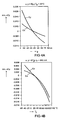
- 3A shows a relative luminous flux ⁇ v / ⁇ v (250 ° C ) as a function of temperature for a red LED.
- 3B shows the change of a dominant wavelength ⁇ over the temperature for the red LED.
- the brightness of the red LED can be adjusted via the duty cycle of a PWM.
- the current through the red LED can be increased, causing a nonlinear change in the flux of light with the current. In both cases (changing the current through the red LED or changing the PWM value) there is no significant change in the dominant wavelength and thus the color location of the red LED.
- White LEDs also show changes in brightness and color (see Fig.4A and Fig.4B ).
- the color space can be described eg with coordinates according to CIE 1931 as ⁇ v - Cx-Cy.
- the tristimulus (X, Y, Z) space can be used.
- the control is designed so that the change vectors of the Sumfarbortortes ⁇ i d cx i d T . ⁇ i d Cy i d T . ⁇ i d ⁇ vi d T by change vectors ⁇ i d cx i d PWM i + d cx ⁇ ei ⁇ ß d I ⁇ ei ⁇ ß ; ⁇ i d Cy i d PWM i + d Cy ⁇ ei ⁇ ß d I ⁇ ei ⁇ ß ; ⁇ i d ⁇ vi d PWM i + d ⁇ V ⁇ ei ⁇ ß d I ⁇ ei ⁇ ß canceled or approximately canceled.
- this correction can also be realized via a control with the aid of a lookup table.
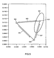
- Figure 5 shows a diagram with a target color location 502, which lies approximately in the middle of an ellipse 501.
- the Ellipse 501 exemplifies a color temperature of 2700K, the color temperature is on the Planckian curve and has a diameter of 3 SWE. Changes within this ellipse 501 are not perceived (or disturbed) by the untrained human eye.
- the brightness of the red LED can be increased to 145% (corresponds to a current increase of approx. 170% to approx. 600mA), a correction is made d ⁇ vrot d PWM red in the direction of an arrow 505 to a color location 506.
Description
- Die Erfindung betrifft ein Verfahren zur Einstellung eines Farborts.
-
WO 2009/039132 A1 offenbart ein System zur Steuerung der Intensität und des Spektrums eines Halbleiterbeleuchtungssystems. - Für Leuchten ist es vorteilhaft, wenn eine Licht mit einem Farbort auf oder nahe dem Planckschen Kurvenzug, vorzugsweise mit einer Farbtemperatur zwischen 2000K und 4000K oder an einem Normfarbort nach IEC 60081, effizient erzeugt werden kann. Insbesondere können hierfür Leuchtdioden (LEDs) eingesetzt werden. Ein Ziel besteht darin, eine hohe Farbwiedergabe bzw. eine in weiten Bereichen nahezu konstante Farbtreue zu erreichen.
- Insbesondere können phosphorkonvertierte Leuchtdioden eingesetzt werden in einem bestimmten Bereich im Cx-Cy-Farbdiagramm oberhalb des Planckschen Kurvenzuges. Um einen Farbort auf dem Planckschen Kurvenzug zu erreichen, können zusätzlich rote Leuchtdioden eingesetzt werden. Hierdurch lässt sich ein hoher Farbwiedergabeindex Ra(8)>90 erzielen.
- Leuchten nach dem Stand der Technik haben das Problem, dass Helligkeiten und Farborte der eingesetzten Leuchtdioden mit einer Temperaturänderung wandern. Auch unterliegen die einzelnen Leuchtdioden einer Alterung, so dass sich im Verlauf der Zeit der von der Leuchte vermittelte Farbeindruck verändert. Üblich ist für die Leuchte ein Temperaturbereich von 20°C (z.B. beim Einschalten der Leuchte) bis 100°C in einem thermisch eingeschwungenen Zustand.
- Es ist eine Leuchte bekannt, die rote Leuchtdioden aufweist und bei der die Helligkeit der roten Leuchtdioden mittels eines Sensors gemessen wird. Der Strom durch die Leuchtdioden oder eine Pulsweitenmodulation (PWM) werden so nachgeführt, dass der Summenfarbort der Leuchte näherungsweise konstant ist.
- Hierbei ist es von Nachteil, dass der Farbort aufgrund der Verschiebung der Dominantwellenlänge der roten LED mit steigender Temperatur (typisch um +0,07nm/K) wandert. Dies führt zu einer Verschiebung des Summenfarbortes um etwa drei MacAdams-Schwellwerteinheiten (SWE) gegenüber dem ursprünglichen Farbort. Insoweit ist mit sich ändernder Temperatur auch die Veränderung des Farborts von einem Nutzer wahrnehmbar.
- Die Aufgabe der Erfindung besteht darin, die vorstehend genannten Nachteile zu vermeiden und insbesondere eine effiziente Möglichkeit anzugeben, den Farbort einer Leuchte (weitgehend) konstant zu halten.
- Diese Aufgabe wird gemäß den Merkmalen der unabhängigen Patentansprüche gelöst. Weiterbildungen der Erfindung ergeben sich auch aus den abhängigen Ansprüchen.
- Zur Lösung der Aufgabe wird ein Verfahren zur Einstellung eines Farborts einer Leuchte umfassend mindestens eine phosphorkonvertierte Leuchtdiode und mindestens eine monochromatische Leuchtdiode, angegeben,
- bei dem ein Strom für die mindestens eine phosphorkonvertierte Leuchtdiode eingestellt wird;
- bei dem eine Pulsweitenmodulation für die mindestens eine phosphorkonvertierte Leuchtdiode eingestellt wird;
- bei dem ein Strom oder eine Pulsweitenmodulation für die mindestens eine monochromatische Leuchtdiode eingestellt wird.
- Bei der Leuchtdiode kann es sich jeweils um ein beliebiges Halbleiterleuchtelement handeln.
- Somit entspricht eine Anzahl der eingesetzten LED-Farben einer Anzahl der zu regelnden und/oder zu steuernden lichttechnischen Parameter, z.B. einer Helligkeit, CIE-Koordinaten (Cx, Cy) oder Tristimulus-Koordinaten (X, Y, Z) minus eins. Somit erfolgt eine Regelung bzw. Steuerung nicht allein über die Helligkeiten der einzelnen Farben. Vorteilhaft wird die Steuerung bzw. Regelung also über die erwähnte Kombination von Strom und Pulsweitenmodulation der einzelnen Typen von Leuchtdioden vorgenommen.
- Hierbei bedeutet Einstellung der Pulsweitenmodulation insbesondere, dass das Tastverhältnis (aktiv/inaktiv) pro Zeitintervall zur Ansteuerung der jeweiligen LED einstellbar ist. Beispielweise bedeutet eine 50%ige Pulsweitenmodulation, dass innerhalb eines vorgegebenen Zeitintervalls die Leuchtdiode zu 50% aktiv und zu 50% inaktiv geschaltet ist.
- Die phosphorkonvertierte LED weist beispielsweise einen wellenlängenkonvertierenden Leuchtstoff, zum Beispiel auf Basis von Granaten wie YAG:Ce, auf. Eine solche LED kann beispielsweise gelbliches, grünliches, blau-grünliches oder rötliches Licht emittieren.
- Eine Weiterbildung ist es, dass der Farbort eingestellt wird in Abhängigkeit von einem Sollfarbort, insbesondere in Abhängigkeit von einem Schwellwert um den Sollfarbort.
- Somit kann bei Erreichen des Schwellwerts um den Sollfarbort eine Korrektur des Farborts veranlasst werden. Der Schwellwert kann so gewählt werden, dass das menschliche Auge eine Veränderung des Farborts bis zu diesem Schwellwert noch (nahezu) nicht wahrnimmt.
- Eine andere Weiterbildung ist es, dass ein Istwert mittels mindestens eines Sensors bestimmt wird, wobei eine Abweichung zwischen dem Istwert und dem Sollfarbort ermittelt wird und entsprechend der Farbort so eingestellt wird, dass der Sollfarbort erreicht wird.
- Hierbei kann der Sollfarbort genau oder mit einer vorgegebenen Unschärfe eingestellt werden. Beispielsweise ist es möglich, den Sollfarbort innerhalb einer MacAdams Ellipse mit einer vorgegebenen Anzahl von MacAdams Schwellwerteinheiten zu bestimmen.
- Insbesondere ist es eine Weiterbildung, dass der mindestens eine Sensor einen optischen Sensor umfasst.
- Auch ist es eine Weiterbildung, dass der Istwert ermittelt wird
- gemäß einem CIE CxCy-Farbraum,
- gemäß einem CIE uv-Farbraum,
- gemäß einem CIE u'v'-Farbraum und/oder
- gemäß einem Tristimulus XYZ-Raum.
- Insbesondere können beliebige Farbräume vorgesehen sein.
- Ferner ist es eine Weiterbildung, dass der Istwert in die folgenden Regelparameter zur Einstellung des Farborts umgesetzt wird:
- den Strom für die mindestens eine phosphorkonvertierte Leuchtdiode;
- die Pulsweitenmodulation für die mindestens eine phosphorkonvertierte Leuchtdiode;
- den Strom für die mindestens eine monochromatische Leuchtdiode.
- Auch ist es möglich, dass der Istwert in die folgenden Regelparameter zur Einstellung des Farborts umgesetzt wird:
- den Strom für die mindestens eine phosphorkonvertierte Leuchtdiode;
- die Pulsweitenmodulation für die mindestens eine phosphorkonvertierte Leuchtdiode;
- die Pulsweitenmodulation für die mindestens eine monochromatische Leuchtdiode.
- Somit erfolgt eine Umsetzung des Farbraums des Istwerts in einen Zielfarbraum, der anhand der beschriebenen Regelparameter bestimmt ist.
- Im Rahmen einer zusätzlichen Weiterbildung ist die Einstellung des Farbraums mittels einer Lookup-Tabelle erfolgt.
- Somit kann die Ermittlung der Regelparameter des Zielfarbraums berechnet werden oder es können anhand der Istwerte ohne gesonderte Berechnung oder Transformation die Regelparameter aus einer Struktur vorab-gespeicherter Werte ermittelt werden.
- Eine nächste Weiterbildung besteht darin, dass die phosphorkonvertierte Leuchtdiode Licht in mindestens einer der folgenden Farben emittiert:
- Weißes Licht,
- violettes Licht,
- grünliches Licht,
- rötliches Licht.
- Eine Ausgestaltung ist es, dass die monochromatische Leuchtdiode eine rote Leuchtdiode ist.
- Ausführungsbeispiele der Erfindung werden nachfolgend anhand der Zeichnungen dargestellt und erläutert.
- Es zeigen:
- Fig.1
- eine schematische Darstellung einer Vorrichtung für eine Leuchte mit zwei phosphorkonvertierten LEDs und einer monochromatischen LED;
- Fig.2
- ein schematisches Ablaufdiagramm mit Schritten zur Einstellung des Farborts der Leuchte;
- Fig.3A
- ein Diagramm zur Visualisierung eines relativen Lichtstroms als Funktion der Temperatur für eine rote LED;
- Fig.3B
- ein Diagramm zur Visualisierung einer Veränderung der Dominantwellenlänge über die Temperatur für eine rote LED;
- Fig.4A
- ein Diagramm mit einer Farbortverschiebung abhängig von einem Strom durch eine weiße LED;
- Fig.4B
- ein Diagramm mit einer Farbortverschiebung abhängig von der Temperatur für eine weiße LED;
- Fig.5
- ein Diagramm mit einem Sollfarbort, der in etwa inmitten einer Ellipse liegt, wobei Schritte zur Regelung auf diesen Sollfarbort erläutert werden.
- Der hier vorgestellte Ansatz erlaubt es, bei einer Lampe oder Leuchte umfassend mehrere Leuchtdioden einen (nahezu) konstanten Farbort einzustellen und (weitgehend) aufrecht zu halten.
- Hierbei sei angemerkt, dass eine Leuchtdiode auch jedwedes Halbleiterleuchtelement umfassen kann.
- Die vorgeschlagene Leuchte umfasst mindestens eine monochrome LED (z.B. mit der Farbe rot oder einer rötlichen Färbung) sowie mindestens eine "weiße" LED. Bei der "weißen" LED handelt es sich um eine phosphorkonvertierte LED. Hierbei sei angemerkt, dass die phosphorkonvertierte LED nicht auf die Emission von "weißem" Licht beschränkt ist. Vielmehr gibt es auch Phosphore, die z.B. eine Emission von violettem, grünlichem oder auch rötlichem Licht erlauben.
- Es werden folgende Möglichkeiten zur Regelung und/oder Steuerung vorgeschlagen:
- (a) PWM der monochromen LED (rot) und
Stromregelung der weißen LED und
PWM der weißen LED; - (b) Stromregelung der monochromen LED (rot) und Stromregelung der weißen LED und
PWM der weißen LED. - Somit werden für die phosphorkonvertierte LED (hier auch als "weiße" LED bezeichnet) eine Stromregelung und eine PWM durchgeführt, während für die monochrome LED eine Stromregelung oder eine PWM durchgeführt wird.
- Es wird daher ausgenutzt, dass sich der Farbort der phosphorkonvertierten LED mit dem Strom verschiebt, bei einer PWM-Regelung aber nicht.
- Somit gibt es in dem vorstehend genannten Ansätzen (a) und (b) jeweils drei unabhängige Steuer- bzw. Regelgrößen, die linear unabhängige Änderungen in einem (dreidimensionalen) Farbraum bewirken. Damit lassen sich Farbort und Helligkeit (im Rahmen von Mess- und Regelgenauigkeiten) steuern oder regeln.
- Mittels der drei Steuer- bzw. Regelgrößen können Helligkeit und Farbort der Leuchte nachgeführt werden ohne dass weitere LEDs vorzusehen wären oder zusätzlicher Regelaufwand nötig würde.
-
Fig.1 zeigt eine schematische Darstellung einer Vorrichtung für eine Leuchte 110. - Die Leuchte 110 umfasst ein Leuchtelement 109 mit einer ggf. mehrstufigen Mischoptik 101, 102, einer roten LED 104 und zwei weißen LED 103, 105. Ein Sensor 106 ist an dem Leuchtelement 109 angeordnet. Der Sensor 106 ist ein optischer Sensor. Der Sensor 106 ist mit einem Mikrokontroller 107 verbunden, der abhängig von dem mittels des Sensors 106 detektierten Signals einen LED Treiber 108 ansteuert. Die LEDs 103 bis 105 sind jeweils mit dem LED Treiber 108 verbunden.
- Der LED Treiber 108 umfasst eine Stromquelle für die rote LED 104 mit einer Stromregelung oder mit einer PWM-Regelung. Weiterhin umfasst der LED Treiber 108 eine Stromquelle für die weißen LEDs 103, 105 mit einer Stromregelung und mit einer PWM-Regelung.
- Hierbei sei angemerkt, dass mehrere (auch unterschiedliche) Sensoren an verschiedenen Orten in der Leuchte 110 und/oder außerhalb der Leuchte 110 vorgesehen sein können.
- Die Regelung des Farborts der Leuchte 110 kann beispielsweise durch eine Korrektur der über den Sensor 106 detektierten Werte erfolgen. Diese Korrektur umfasst eine Transformation der Abweichungsvektoren (Cx, Cy, Helligkeit) in ein Koordinatensystem der Änderungsvektoren der Regelparameter (PWM rot, Strom weiß und PWM weiß). Der Mikrokontroller 107 regelt z.B. über eine PID-Regelung in jedem Regelparameter den Summenfarbort und die Helligkeit auf den Sollwert. Die Abweichung vom Sollwert kann z.B. deutlich unter 1 SWE und damit für das menschliche Auge unsichtbar gehalten werden.
-
Fig.2 zeigt ein schematisches Ablaufdiagramm mit Schritten zur Einstellung des Farborts der Leuchte. - In einem Schritt 201 werden die Leuchtdioden mit einem vorgegebenen Strom bzw. PWM-Wert beaufschlagt. Dies dient der Voreinstellung vor Beginn der eigentlichen Regelung.
- In einem Schritt 202 wird/werden
- der Summenfarbort der Leuchte oder
- die Helligkeiten der LEDs
- In einem anschließenden Schritt 203 erfolgt ein Vergleich zwischen dem IST-Zustand mit einem Sollfarbort und/oder einer Sollhelligkeit. In einem Schritt 204 wird eine Korrektur in Richtung der Sollwerte (Sollfarbort und/oder Sollhelligkeit) bestimmt. Hierzu werden Regelparameter
- Helligkeit (Strom und PWM-Wert) der roten LED,
- Strom für die weißen LEDs,
- PWM-Wert für die weißen LEDs
- Schließlich wird in einem Schritt 205 eine Änderung der Regelparameter durchgeführt und somit eine Farbortveränderung der Leuchte korrigiert.
- Diese Regelung kann automatisch zu bestimmten Zeitpunkten (z.B. iterative alle n Minuten) durchgeführt werden. Auch ist es möglich, dass die Regelung über ein Ausmaß einer Veränderung gestartet wird; so kann z.B. eine von dem Sensor festgestellte Veränderung ursächlich für die Regelung sein. Hierzu kann ein Schwellwertvergleich eingesetzt werden und z.B. bei einem Erreichen oder Überschreiten des Sollwerts kann die Regelung gestartet werden.
-
Fig.3A zeigt einen relativen Lichtstrom φv/φv(250°C) als Funktion der Temperatur für eine rote LED.Fig.3B zeigt die Veränderung einer Dominantwellenlänge λ über die Temperatur für die rote LED. - Es zeigt sich, dass die rote LED zum einen mit steigender Temperatur an Helligkeit verliert, es gilt näherungsweise:

- Gleichzeitig ändert sich mit der Temperatur die Dominantwellenlänge λ mit

- In CIE 1931-Koordinaten entspricht dies in etwa

und
- Die Helligkeit der roten LED lässt sich über das Tastverhältnis einer PWM einstellen. Alternativ kann der Strom durch die rote LED erhöht werden, was eine nichtlineare Änderung des Lichtflusses mit dem Strom bewirkt. In beiden Fällen (Änderung des Stroms durch die rote LED oder Änderung des PWM-Werts) ergibt sich keine wesentliche Änderung der Dominantwellenlänge und damit des Farbortes der roten LED.
- Beispielhaft kann im Folgenden von einer PWM-Regelung der Helligkeit ausgegangen werden, also

- Weiße LEDs zeigen ebenfalls Helligkeits- und Farbortänderungen (siehe
Fig.4A und Fig.4B ). - Aus
Fig.4A folgt für die Farbortverschiebung der weißen LED in einem Temperaturbereich von 20°C bis 100°C näherungsweise

- Für ultraweiße LEDs gilt z.B. in etwa eine Verschiebung von


- Entsprechend zur roten LED gilt auch bei der weißen LED:

- Eingesetzte weiße LEDs können ihre Helligkeit mit dem Strom in etwa wie folgt ändern:

mit
a = 1,53 und Is = 0,38A. - Der Farbraum kann z.B. mit Koordinaten nach CIE 1931 als φv--Cx-Cy beschrieben werden. Alternativ lässt sich der Tristimulus (X, Y, Z)-Raum verwenden.
- Vorzugsweise wird die Regelung so ausgelegt, dass die Änderungsvektoren des Summenfarbortes

durch Änderungsvektoren


aufgehoben oder näherungsweise aufgehoben werden. - Alternativ kann diese Korrektur auch über eine Steuerung mit Hilfe einer Lookup-Table realisiert werden.
-
Fig.5 zeigt ein Diagramm mit einem Sollfarbort 502, der in etwa inmitten einer Ellipse 501 liegt. Die Ellipse 501 entspricht beispielhaft einer Farbtemperatur von 2700K, die Farbtemperatur liegt auf dem Planckschen Kurvenzug und hat einen Durchmesser von 3 SWE. Veränderungen innerhalb dieser Ellipse 501 werden vom ungeübten menschlichen Auge nicht (oder nicht als störend) wahrgenommen. - Die Ansteuerung der Leuchtdioden (entsprechend dem Beispiel von
Fig.1 : Zwei weiße LEDs und eine rote LED) ist wie folgt: - Weiße LEDs: Imax = 700mA; 60% PWM;
- Rote LED: 350mA konstant.
- Bei einer Erhöhung der Temperatur ohne Korrektur

verschiebt sich der Farbort der Leuchte in Richtung eines Pfeils 503 zu einem Farbort 504. - Nun kann die Helligkeit der roten LED auf 145% (entspricht einer Stromerhöhung von ca. 170% auf ca. 600mA) erhöht werden, es erfolgt eine Korrektur

in Richtung eines Pfeils 505 zu einem Farbort 506. - Jetzt erfolgt eine Korrektur

indem der Strom der weißen LEDs auf 350mA reduziert und die PWM für die weißen LEDs auf 100% angehoben wird. Dadurch wandert der Farbort in Richtung eines Pfeils 507 zum Sollfarbort 502. -
- Cx
- x-Koordinate im CIE 1931 Farbraum
- Cy
- y-Koordinate im CIE 1931 Farbraum
- LED
- Leuchtdiode
- PWM
- Pulsweitenmodulation
- SWE
- MacAdams Schwellwerteinheit
-
- 101
- optische Komponente
- 102
- optische Komponente
- 103
- weiße LED
- 104
- rote LED
- 105
- weiße LED
- 106
- Sensor (optischer Sensor)
- 107
- Mikrokontroller
- 108
- LED Treiber
- 109
- Leuchtelement
- 110
- Leuchte
- 201 bis 205
- Verfahrensschritte zur Regelung des Farborts einer Leuchte
- 501
- Ellipse
- 502
- Sollfarbort
- 503
- Pfeil
- 504
- Farbort
- 505
- Pfeil
- 506
- Farbort
- 507
- Pfeil
Claims (7)
- Verfahren zur Einstellung eines Farborts einer Leuchte (110) umfassend mindestens eine phosphorkonvertierte Leuchtdiode (103, 105) und mindestens eine monochromatische Leuchtdiode (104),- bei dem ein Strom für die mindestens eine phosphorkonvertierte Leuchtdiode (103, 105) eingestellt wird;- bei dem eine Pulsweitenmodulation für die mindestens eine phosphorkonvertierte Leuchtdiode (103, 105) eingestellt wird, dadurch gekennzeichnet, dass- bei dem Verfahren entweder ein Strom oder eine Pulsweitenmodulation für die mindestens eine monochromatische Leuchtdiode (104) eingestellt wird,- wobei der Farbort eingestellt wird in Abhängigkeit von einem Sollfarbort, insbesondere in Abhängigkeit von einem Schwellwert um den Sollfarbort, wobei ein Istwert mittels mindestens eines Sensors bestimmt wird, wobei eine Abweichung zwischen dem Istwert und dem Sollfarbort ermittelt wird und entsprechend der Farbort so eingestellt wird, dass der Sollfarbort erreicht wird und- bei dem der mindestens eine Sensor einen optischen Sensor umfasst.
- Verfahren nach Anspruch 1, bei dem der Istwert ermittelt wird- gemäß einem CIE CxCy-Farbraum,- gemäß einem CIE uv-Farbraum,- gemäß einem CIE u'v'-Farbraum und/oder- gemäß einem Tristimulus XYZ-Raum.
- Verfahren nach Anspruch 1, bei dem der Istwert in die folgenden Regelparameter zur Einstellung des Farborts umgesetzt wird:- den Strom für die mindestens eine phosphorkonvertierte Leuchtdiode;- die Pulsweitenmodulation für die mindestens eine phosphorkonvertierte Leuchtdiode;- den Strom für die mindestens eine monochromatische Leuchtdiode.
- Verfahren nach einem der Ansprüche 1 bis 3, bei dem der Istwert in die folgenden Regelparameter zur Einstellung des Farborts umgesetzt wird:- den Strom für die mindestens eine phosphorkonvertierte Leuchtdiode;- die Pulsweitenmodulation für die mindestens eine phosphorkonvertierte Leuchtdiode;- die Pulsweitenmodulation für die mindestens eine monochromatische Leuchtdiode.
- Verfahren nach einem der vorhergehenden Ansprüche, bei dem die Einstellung des Farborts mittels einer Lookup-Tabelle erfolgt.
- Verfahren nach einem der vorhergehenden Ansprüche, bei dem die phosphörkonvertierte Leuchtdiode Licht in mindestens einer der folgenden Farben emittiert:- Weißes Licht,- violettes Licht,- grünliches Licht,- rötliches Licht.
- Verfahren nach einem der vorhergehenden Ansprüche, bei dem die monochromatische Leuchtdiode eine rote Leuchtdiode ist.
Applications Claiming Priority (3)
| Application Number | Priority Date | Filing Date | Title |
|---|---|---|---|
| DE102009021845 | 2009-05-19 | ||
| DE102009048871A DE102009048871A1 (de) | 2009-05-19 | 2009-09-23 | Verfahren und Vorrichtung zur Einstellung eines Farborts |
| PCT/EP2010/056478 WO2010133481A1 (de) | 2009-05-19 | 2010-05-11 | Verfahren und vorrichtung zur einstellung eines farborts |
Publications (2)
| Publication Number | Publication Date |
|---|---|
| EP2433472A1 EP2433472A1 (de) | 2012-03-28 |
| EP2433472B1 true EP2433472B1 (de) | 2014-07-30 |
Family
ID=42993724
Family Applications (1)
| Application Number | Title | Priority Date | Filing Date |
|---|---|---|---|
| EP10720393.7A Active EP2433472B1 (de) | 2009-05-19 | 2010-05-11 | Verfahren zur einstellung eines farborts |
Country Status (5)
| Country | Link |
|---|---|
| US (1) | US8604702B2 (de) |
| EP (1) | EP2433472B1 (de) |
| CN (1) | CN102428755B (de) |
| DE (1) | DE102009048871A1 (de) |
| WO (1) | WO2010133481A1 (de) |
Families Citing this family (9)
| Publication number | Priority date | Publication date | Assignee | Title |
|---|---|---|---|---|
| US20100245279A1 (en) * | 2009-03-31 | 2010-09-30 | Robe Lighting S.R.O. | Display and display control system for an automated luminaire |
| DE102010030061A1 (de) * | 2010-06-15 | 2011-12-15 | Osram Gesellschaft mit beschränkter Haftung | Verfahren zum Betreiben einer Halbleiterleuchtvorrichtung und Farbregelvorrichtung zum Durchführen des Verfahrens |
| CN104684216A (zh) * | 2015-02-11 | 2015-06-03 | 广州市德晟照明实业有限公司 | Led灯具过温保护电路及方法 |
| TWI565905B (zh) * | 2016-01-27 | 2017-01-11 | 國立清華大學 | 高品質光源的組合方法 |
| CN107017240B (zh) * | 2016-01-27 | 2019-08-20 | 周卓辉 | 光源的组合方法 |
| CN108401314B (zh) * | 2018-01-29 | 2019-12-13 | 杭州电子科技大学 | 基于极坐标的无极调光调色方法 |
| US10645778B1 (en) * | 2018-02-13 | 2020-05-05 | Tomar Electronics, Inc. | Methods of color selection in multiple color LED lamps |
| US11054090B2 (en) * | 2019-01-29 | 2021-07-06 | Intematix Corporation | High gamut index solid-state white light emitting devices |
| US11289630B2 (en) | 2019-12-20 | 2022-03-29 | Lumileds Llc | Tunable lighting system with preferred color rendering |
Family Cites Families (5)
| Publication number | Priority date | Publication date | Assignee | Title |
|---|---|---|---|---|
| US7764026B2 (en) * | 1997-12-17 | 2010-07-27 | Philips Solid-State Lighting Solutions, Inc. | Systems and methods for digital entertainment |
| KR100813382B1 (ko) * | 2003-07-28 | 2008-03-12 | 니치아 카가쿠 고교 가부시키가이샤 | 발광장치, led조명, led발광장치 및 발광장치의제어방법 |
| US7009343B2 (en) * | 2004-03-11 | 2006-03-07 | Kevin Len Li Lim | System and method for producing white light using LEDs |
| WO2008139369A1 (en) | 2007-05-10 | 2008-11-20 | Philips Intellectual Property & Standards Gmbh | Lighting device with a plurality of light emitters |
| US8368636B2 (en) * | 2007-09-21 | 2013-02-05 | Point Somee Limited Liability Company | Regulation of wavelength shift and perceived color of solid state lighting with intensity variation |
-
2009
- 2009-09-23 DE DE102009048871A patent/DE102009048871A1/de not_active Withdrawn
-
2010
- 2010-05-11 US US13/321,819 patent/US8604702B2/en active Active
- 2010-05-11 CN CN201080021923.5A patent/CN102428755B/zh not_active Expired - Fee Related
- 2010-05-11 EP EP10720393.7A patent/EP2433472B1/de active Active
- 2010-05-11 WO PCT/EP2010/056478 patent/WO2010133481A1/de active Application Filing
Also Published As
| Publication number | Publication date |
|---|---|
| DE102009048871A1 (de) | 2010-11-25 |
| US8604702B2 (en) | 2013-12-10 |
| US20120068610A1 (en) | 2012-03-22 |
| CN102428755B (zh) | 2015-05-27 |
| CN102428755A (zh) | 2012-04-25 |
| EP2433472A1 (de) | 2012-03-28 |
| WO2010133481A1 (de) | 2010-11-25 |
Similar Documents
| Publication | Publication Date | Title |
|---|---|---|
| EP2433472B1 (de) | Verfahren zur einstellung eines farborts | |
| EP2701464B1 (de) | Vorrichtung und Verfahren zur Erzeugung von Licht eines vorgegebenen Spektrums mit mindestens vier verschiedenfarbigen Lichtquellen | |
| EP2177078B1 (de) | Vorrichtung und verfahren zur steuerung der lichtabgabe | |
| EP1938667B1 (de) | Lichtquelle, die mischfarbiges licht aussendet, und verfahren zur steuerung des farbortes einer solchen lichtquelle | |
| DE60219504T2 (de) | Led steuerungsgerät | |
| EP2005799B1 (de) | Farbtemperatur- und farbortsteuerung für eine leuchte | |
| EP2901815B1 (de) | Verfahren und anordnung zur temperaturkorrigierten steuerung von leds, mittels look-up-tabellen | |
| DE102017125405B4 (de) | Verfahren und Vorrichtung zum Kalibrieren und Betreiben einer RGB-LED-Beleuchtung | |
| DE102008029816A1 (de) | Schaltung zur Dimmung einer Lampe und zugehöriges Verfahren | |
| DE102010030061A1 (de) | Verfahren zum Betreiben einer Halbleiterleuchtvorrichtung und Farbregelvorrichtung zum Durchführen des Verfahrens | |
| DE102010000672A1 (de) | Kombiniertes Verfahren zum Betreiben eines elektrischen Leuchtmittels sowie Betriebsschaltung | |
| DE102013111662A1 (de) | Beleuchtungsvorrichtung und Verfahren zu deren Betrieb | |
| DE112015004032T5 (de) | Led-dentallichtquelle mit veränderlicher chromatizität und verfahren | |
| DE102007004834A1 (de) | Lichtgerät und Verfahren zur Realisierung einer gewünschten Farbmischung | |
| DE102012207185A1 (de) | Anordnung zur Erzeugung von weißem Licht mit einstellbarer Farbtemperatur | |
| EP2367401A2 (de) | Vorrichtung mit einem Leuchtmittel und Verfahren zu dessen Steuerung | |
| EP2375870B1 (de) | Verfahren und System zur Lichtsteuerung | |
| EP3032918B1 (de) | Verfahren zum Betreiben einer zum Emittieren von in seiner Helligkeit und/oder seinem Farbort einstellbarem Licht eingerichteten Anordnung | |
| DE102007055670B4 (de) | Verfahren zum Umsteuern zwischen Mischlichtfarben | |
| EP2473007B1 (de) | LED-Modul zur passiven Lichtstromstabilisierung | |
| DE112014002422T5 (de) | Mehrfarblichtquellenvorichtung | |
| DE102012213038A1 (de) | Farbortdetektion | |
| DE102016103677A1 (de) | Verfahren zur Steuerung einer Leuchteinrichtung und Leuchteinrichtung | |
| EP2915412A1 (de) | Verfahren zum betreiben einer lichtquelle mit mehreren leds oder led-gruppen | |
| DE102011016867B4 (de) | Verfahren zum Ansteuern einer Leuchte sowie Leuchte |
Legal Events
| Date | Code | Title | Description |
|---|---|---|---|
| PUAI | Public reference made under article 153(3) epc to a published international application that has entered the european phase |
Free format text: ORIGINAL CODE: 0009012 |
|
| 17P | Request for examination filed |
Effective date: 20111028 |
|
| AK | Designated contracting states |
Kind code of ref document: A1 Designated state(s): AL AT BE BG CH CY CZ DE DK EE ES FI FR GB GR HR HU IE IS IT LI LT LU LV MC MK MT NL NO PL PT RO SE SI SK SM TR |
|
| DAX | Request for extension of the european patent (deleted) | ||
| RAP1 | Party data changed (applicant data changed or rights of an application transferred) |
Owner name: OSRAM GMBH |
|
| RAP1 | Party data changed (applicant data changed or rights of an application transferred) |
Owner name: OSRAM GMBH |
|
| GRAP | Despatch of communication of intention to grant a patent |
Free format text: ORIGINAL CODE: EPIDOSNIGR1 |
|
| INTG | Intention to grant announced |
Effective date: 20131213 |
|
| GRAP | Despatch of communication of intention to grant a patent |
Free format text: ORIGINAL CODE: EPIDOSNIGR1 |
|
| INTG | Intention to grant announced |
Effective date: 20140424 |
|
| GRAS | Grant fee paid |
Free format text: ORIGINAL CODE: EPIDOSNIGR3 |
|
| GRAA | (expected) grant |
Free format text: ORIGINAL CODE: 0009210 |
|
| AK | Designated contracting states |
Kind code of ref document: B1 Designated state(s): AL AT BE BG CH CY CZ DE DK EE ES FI FR GB GR HR HU IE IS IT LI LT LU LV MC MK MT NL NO PL PT RO SE SI SK SM TR |
|
| REG | Reference to a national code |
Ref country code: GB Ref legal event code: FG4D Free format text: NOT ENGLISH |
|
| REG | Reference to a national code |
Ref country code: CH Ref legal event code: EP |
|
| REG | Reference to a national code |
Ref country code: AT Ref legal event code: REF Ref document number: 680496 Country of ref document: AT Kind code of ref document: T Effective date: 20140815 |
|
| REG | Reference to a national code |
Ref country code: IE Ref legal event code: FG4D Free format text: LANGUAGE OF EP DOCUMENT: GERMAN |
|
| REG | Reference to a national code |
Ref country code: DE Ref legal event code: R096 Ref document number: 502010007558 Country of ref document: DE Effective date: 20140911 |
|
| REG | Reference to a national code |
Ref country code: NL Ref legal event code: VDEP Effective date: 20140730 |
|
| REG | Reference to a national code |
Ref country code: LT Ref legal event code: MG4D |
|
| PG25 | Lapsed in a contracting state [announced via postgrant information from national office to epo] |
Ref country code: ES Free format text: LAPSE BECAUSE OF FAILURE TO SUBMIT A TRANSLATION OF THE DESCRIPTION OR TO PAY THE FEE WITHIN THE PRESCRIBED TIME-LIMIT Effective date: 20140730 Ref country code: LT Free format text: LAPSE BECAUSE OF FAILURE TO SUBMIT A TRANSLATION OF THE DESCRIPTION OR TO PAY THE FEE WITHIN THE PRESCRIBED TIME-LIMIT Effective date: 20140730 Ref country code: BG Free format text: LAPSE BECAUSE OF FAILURE TO SUBMIT A TRANSLATION OF THE DESCRIPTION OR TO PAY THE FEE WITHIN THE PRESCRIBED TIME-LIMIT Effective date: 20141030 Ref country code: NO Free format text: LAPSE BECAUSE OF FAILURE TO SUBMIT A TRANSLATION OF THE DESCRIPTION OR TO PAY THE FEE WITHIN THE PRESCRIBED TIME-LIMIT Effective date: 20141030 Ref country code: SE Free format text: LAPSE BECAUSE OF FAILURE TO SUBMIT A TRANSLATION OF THE DESCRIPTION OR TO PAY THE FEE WITHIN THE PRESCRIBED TIME-LIMIT Effective date: 20140730 Ref country code: GR Free format text: LAPSE BECAUSE OF FAILURE TO SUBMIT A TRANSLATION OF THE DESCRIPTION OR TO PAY THE FEE WITHIN THE PRESCRIBED TIME-LIMIT Effective date: 20141031 Ref country code: FI Free format text: LAPSE BECAUSE OF FAILURE TO SUBMIT A TRANSLATION OF THE DESCRIPTION OR TO PAY THE FEE WITHIN THE PRESCRIBED TIME-LIMIT Effective date: 20140730 Ref country code: PT Free format text: LAPSE BECAUSE OF FAILURE TO SUBMIT A TRANSLATION OF THE DESCRIPTION OR TO PAY THE FEE WITHIN THE PRESCRIBED TIME-LIMIT Effective date: 20141202 |
|
| PG25 | Lapsed in a contracting state [announced via postgrant information from national office to epo] |
Ref country code: IS Free format text: LAPSE BECAUSE OF FAILURE TO SUBMIT A TRANSLATION OF THE DESCRIPTION OR TO PAY THE FEE WITHIN THE PRESCRIBED TIME-LIMIT Effective date: 20141130 Ref country code: NL Free format text: LAPSE BECAUSE OF FAILURE TO SUBMIT A TRANSLATION OF THE DESCRIPTION OR TO PAY THE FEE WITHIN THE PRESCRIBED TIME-LIMIT Effective date: 20140730 Ref country code: HR Free format text: LAPSE BECAUSE OF FAILURE TO SUBMIT A TRANSLATION OF THE DESCRIPTION OR TO PAY THE FEE WITHIN THE PRESCRIBED TIME-LIMIT Effective date: 20140730 Ref country code: PL Free format text: LAPSE BECAUSE OF FAILURE TO SUBMIT A TRANSLATION OF THE DESCRIPTION OR TO PAY THE FEE WITHIN THE PRESCRIBED TIME-LIMIT Effective date: 20140730 Ref country code: LV Free format text: LAPSE BECAUSE OF FAILURE TO SUBMIT A TRANSLATION OF THE DESCRIPTION OR TO PAY THE FEE WITHIN THE PRESCRIBED TIME-LIMIT Effective date: 20140730 Ref country code: CY Free format text: LAPSE BECAUSE OF FAILURE TO SUBMIT A TRANSLATION OF THE DESCRIPTION OR TO PAY THE FEE WITHIN THE PRESCRIBED TIME-LIMIT Effective date: 20140730 |
|
| PG25 | Lapsed in a contracting state [announced via postgrant information from national office to epo] |
Ref country code: CZ Free format text: LAPSE BECAUSE OF FAILURE TO SUBMIT A TRANSLATION OF THE DESCRIPTION OR TO PAY THE FEE WITHIN THE PRESCRIBED TIME-LIMIT Effective date: 20140730 Ref country code: SK Free format text: LAPSE BECAUSE OF FAILURE TO SUBMIT A TRANSLATION OF THE DESCRIPTION OR TO PAY THE FEE WITHIN THE PRESCRIBED TIME-LIMIT Effective date: 20140730 Ref country code: DK Free format text: LAPSE BECAUSE OF FAILURE TO SUBMIT A TRANSLATION OF THE DESCRIPTION OR TO PAY THE FEE WITHIN THE PRESCRIBED TIME-LIMIT Effective date: 20140730 Ref country code: EE Free format text: LAPSE BECAUSE OF FAILURE TO SUBMIT A TRANSLATION OF THE DESCRIPTION OR TO PAY THE FEE WITHIN THE PRESCRIBED TIME-LIMIT Effective date: 20140730 Ref country code: RO Free format text: LAPSE BECAUSE OF FAILURE TO SUBMIT A TRANSLATION OF THE DESCRIPTION OR TO PAY THE FEE WITHIN THE PRESCRIBED TIME-LIMIT Effective date: 20140730 |
|
| REG | Reference to a national code |
Ref country code: DE Ref legal event code: R097 Ref document number: 502010007558 Country of ref document: DE |
|
| PLBE | No opposition filed within time limit |
Free format text: ORIGINAL CODE: 0009261 |
|
| STAA | Information on the status of an ep patent application or granted ep patent |
Free format text: STATUS: NO OPPOSITION FILED WITHIN TIME LIMIT |
|
| 26N | No opposition filed |
Effective date: 20150504 |
|
| PG25 | Lapsed in a contracting state [announced via postgrant information from national office to epo] |
Ref country code: SI Free format text: LAPSE BECAUSE OF FAILURE TO SUBMIT A TRANSLATION OF THE DESCRIPTION OR TO PAY THE FEE WITHIN THE PRESCRIBED TIME-LIMIT Effective date: 20140730 |
|
| REG | Reference to a national code |
Ref country code: CH Ref legal event code: PL |
|
| GBPC | Gb: european patent ceased through non-payment of renewal fee |
Effective date: 20150511 |
|
| PG25 | Lapsed in a contracting state [announced via postgrant information from national office to epo] |
Ref country code: LU Free format text: LAPSE BECAUSE OF FAILURE TO SUBMIT A TRANSLATION OF THE DESCRIPTION OR TO PAY THE FEE WITHIN THE PRESCRIBED TIME-LIMIT Effective date: 20150511 Ref country code: LI Free format text: LAPSE BECAUSE OF NON-PAYMENT OF DUE FEES Effective date: 20150531 Ref country code: CH Free format text: LAPSE BECAUSE OF NON-PAYMENT OF DUE FEES Effective date: 20150531 Ref country code: MC Free format text: LAPSE BECAUSE OF FAILURE TO SUBMIT A TRANSLATION OF THE DESCRIPTION OR TO PAY THE FEE WITHIN THE PRESCRIBED TIME-LIMIT Effective date: 20140730 |
|
| REG | Reference to a national code |
Ref country code: IE Ref legal event code: MM4A |
|
| PG25 | Lapsed in a contracting state [announced via postgrant information from national office to epo] |
Ref country code: GB Free format text: LAPSE BECAUSE OF NON-PAYMENT OF DUE FEES Effective date: 20150511 Ref country code: IE Free format text: LAPSE BECAUSE OF NON-PAYMENT OF DUE FEES Effective date: 20150511 |
|
| REG | Reference to a national code |
Ref country code: FR Ref legal event code: PLFP Year of fee payment: 7 |
|
| REG | Reference to a national code |
Ref country code: AT Ref legal event code: MM01 Ref document number: 680496 Country of ref document: AT Kind code of ref document: T Effective date: 20150511 |
|
| PG25 | Lapsed in a contracting state [announced via postgrant information from national office to epo] |
Ref country code: AT Free format text: LAPSE BECAUSE OF NON-PAYMENT OF DUE FEES Effective date: 20150511 |
|
| PG25 | Lapsed in a contracting state [announced via postgrant information from national office to epo] |
Ref country code: MT Free format text: LAPSE BECAUSE OF FAILURE TO SUBMIT A TRANSLATION OF THE DESCRIPTION OR TO PAY THE FEE WITHIN THE PRESCRIBED TIME-LIMIT Effective date: 20140730 |
|
| REG | Reference to a national code |
Ref country code: FR Ref legal event code: PLFP Year of fee payment: 8 |
|
| PG25 | Lapsed in a contracting state [announced via postgrant information from national office to epo] |
Ref country code: SM Free format text: LAPSE BECAUSE OF FAILURE TO SUBMIT A TRANSLATION OF THE DESCRIPTION OR TO PAY THE FEE WITHIN THE PRESCRIBED TIME-LIMIT Effective date: 20140730 Ref country code: HU Free format text: LAPSE BECAUSE OF FAILURE TO SUBMIT A TRANSLATION OF THE DESCRIPTION OR TO PAY THE FEE WITHIN THE PRESCRIBED TIME-LIMIT; INVALID AB INITIO Effective date: 20100511 |
|
| PG25 | Lapsed in a contracting state [announced via postgrant information from national office to epo] |
Ref country code: BE Free format text: LAPSE BECAUSE OF NON-PAYMENT OF DUE FEES Effective date: 20150531 |
|
| PG25 | Lapsed in a contracting state [announced via postgrant information from national office to epo] |
Ref country code: TR Free format text: LAPSE BECAUSE OF FAILURE TO SUBMIT A TRANSLATION OF THE DESCRIPTION OR TO PAY THE FEE WITHIN THE PRESCRIBED TIME-LIMIT Effective date: 20140730 |
|
| REG | Reference to a national code |
Ref country code: FR Ref legal event code: PLFP Year of fee payment: 9 |
|
| PG25 | Lapsed in a contracting state [announced via postgrant information from national office to epo] |
Ref country code: MK Free format text: LAPSE BECAUSE OF FAILURE TO SUBMIT A TRANSLATION OF THE DESCRIPTION OR TO PAY THE FEE WITHIN THE PRESCRIBED TIME-LIMIT Effective date: 20140730 |
|
| PG25 | Lapsed in a contracting state [announced via postgrant information from national office to epo] |
Ref country code: AL Free format text: LAPSE BECAUSE OF FAILURE TO SUBMIT A TRANSLATION OF THE DESCRIPTION OR TO PAY THE FEE WITHIN THE PRESCRIBED TIME-LIMIT Effective date: 20140730 |
|
| PGFP | Annual fee paid to national office [announced via postgrant information from national office to epo] |
Ref country code: IT Payment date: 20190527 Year of fee payment: 10 |
|
| PGFP | Annual fee paid to national office [announced via postgrant information from national office to epo] |
Ref country code: FR Payment date: 20190523 Year of fee payment: 10 |
|
| REG | Reference to a national code |
Ref country code: DE Ref legal event code: R079 Ref document number: 502010007558 Country of ref document: DE Free format text: PREVIOUS MAIN CLASS: H05B0033080000 Ipc: H05B0045000000 |
|
| PG25 | Lapsed in a contracting state [announced via postgrant information from national office to epo] |
Ref country code: FR Free format text: LAPSE BECAUSE OF NON-PAYMENT OF DUE FEES Effective date: 20200531 |
|
| PG25 | Lapsed in a contracting state [announced via postgrant information from national office to epo] |
Ref country code: IT Free format text: LAPSE BECAUSE OF NON-PAYMENT OF DUE FEES Effective date: 20200511 |
|
| REG | Reference to a national code |
Ref country code: DE Ref legal event code: R081 Ref document number: 502010007558 Country of ref document: DE Owner name: INVENTRONICS GMBH, DE Free format text: FORMER OWNER: OSRAM GMBH, 80807 MUENCHEN, DE Ref country code: DE Ref legal event code: R081 Ref document number: 502010007558 Country of ref document: DE Owner name: OPTOTRONIC GMBH, DE Free format text: FORMER OWNER: OSRAM GMBH, 80807 MUENCHEN, DE |
|
| PGFP | Annual fee paid to national office [announced via postgrant information from national office to epo] |
Ref country code: DE Payment date: 20230531 Year of fee payment: 14 |
|
| REG | Reference to a national code |
Ref country code: DE Ref legal event code: R081 Ref document number: 502010007558 Country of ref document: DE Owner name: INVENTRONICS GMBH, DE Free format text: FORMER OWNER: OPTOTRONIC GMBH, 85748 GARCHING, DE |